Embed Size (px)
Citation preview
A Modified Droop Control for Reactive Power Sharing in LargeMicrogrids with Meshed Topology
Ramin Moslemi†, Javad Mohammadpour†, and Afshin Mesbahi†
Abstract— The high penetration of distributed energy re-sources (DERs) into smart grids has triggered a move to-wards microgrids with complicated topologies. Droop controlapproaches have proven to be the most practical approach torealize plug and play capability in microgrids. While droopcontrol methods have been a focal point of research interestin the power systems control community, most of the previousworks have been devoted to improve the efficiency of droop con-trollers in microgrids with simple architectures and distributedgenerators (DGs) operating in parallel. This paper presents anew approach to design DG’s output virtual inductance controlloop to improve the reactive power sharing among DGs inmicrogrids with meshed topologies. The proposed approach inthis paper utilizes the Kron reduction method and nonlinearoptimization tools to find the optimal values of the DGs’ outputvirtual inductances to enhance the reactive power sharingbetween DGs’ power electronic inverters.
I. INTRODUCTION
In recent years, a variety of approaches have been pro-posed to regulate the voltage and frequency of microgridsand offer a plug and play capability for distributed energyresources (DERs). Due to the importance of reliability inmicrogrid applications, a decentralized control, also knownas droop control, has been presented as a key method toachieve voltage and frequency regulation and also shareactive and reactive powers among distributed generators(DGs). The main idea behind this approach is to imitatethe behavior of synchronous generators in the conventionalpower systems [1], in which active power P and reactivepower Q are controlled by the frequency signal ω and thevoltage magnitude E, respectively.
The droop controllers were originally proposed for gridswith predominantly inductive lines. However, applying thiscontrol method to medium or low voltage microgrids, inwhich the feeders have mixed or even resistive impedance,could result in a poor transient performance due to the cou-pling between active and reactive powers. Another challengein the implementation of the droop controllers is the “reactivepower sharing mismatch”. Since frequency can be consideredas a global signal among the active power and frequency(P − ω) droop controllers, active power sharing is easyto achieve [2]. However, realizing accurate reactive powersharing is hard to achieve due to the voltage differencesat the inverters’ output terminals caused by unequal lineimpedances or DGs’ different ratings. To reduce the reactivepower sharing inaccuracy, an adaptive voltage droop schemewas presented in [3]. A modified droop controller was also
†Complex Systems Control Lab, College of Engineering, TheUniversity of Georgia, Athens, GA 30602, USA E-mail:moslemi,javadm,[email protected].
proposed in [4] to compensate for the effect of voltage dropscaused by the feeder impedances and the local loads throughmodifying the droop slopes.
Reviewing recent literature reveals that the output virtualimpedance method has been considered as an ultimate so-lution to address droop controlled microgrids’ drawbacks.Implementation of the output virtual impedance loop wasproposed in [6] to eliminate the power coupling. The outputvirtual impedance was also employed in [7]. The afore-described approaches have been successful to address mostof the challenges existing for the power sharing in micro-grids; however, they have been developed for microgridscontaining DGs operating in parallel or for simple architec-ture microgrids with radial topologies. Due to the increasingintegration of DERs into the distribution systems, and inorder to improve the reliability of microgrids to deliver powerto the critical loads in the case of feeder failures, modernmicrogrids are moving toward complicated networks withmeshed topology [8].
In this paper, a new virtual inductance design approachis proposed to achieve the reactive power sharing amongDGs in the droop based microgrids with multiple loads andmeshed topologies. The proposed approach is applicable tomicrogrids with complex topologies, with which most of theconventional droop control methods fail to cope. The newapproach utilizes the concept of Schur complement [9] andthe Kron reduction method [10] to reduce the graph corre-sponding to the microgrid’s network. Then, reactive powersharing problem is addressed on the reduced model. Finally, anonlinear optimization problem is introduced to calculate theoutput virtual inductance values to guarantee reactive powersharing. The proposed process is repeatedly implemented byenergy management system (EMS) at each update interval toprovide the optimal output virtual inductance values basedon the new operating point.
This paper is structured as follows. In Section II, theprinciple of conventional droop method and output virtualimpedance are explained. In Section III, the concept ofKron reduction is presented and the proposed method basedon Kron reduction is described. In Section IV, simulationresults are given and the efficiency of the proposed droopcontrol method will be demonstrated, and finally Section Vconcludes the paper.
II. STRUCTURE OF THE DROOP-BASEDMICROGRIDS
In contrast with the microgrids operating in grid-connectedmode, in autonomous mode, the DGs power electronic in-verters are responsible for regulating voltage and frequencyof the microgrid. Therefore, in the autonomous mode, the
2016 American Control Conference (ACC)Boston Marriott Copley PlaceJuly 6-8, 2016. Boston, MA, USA
978-1-4673-8682-1/$31.00 ©2016 AACC 6779
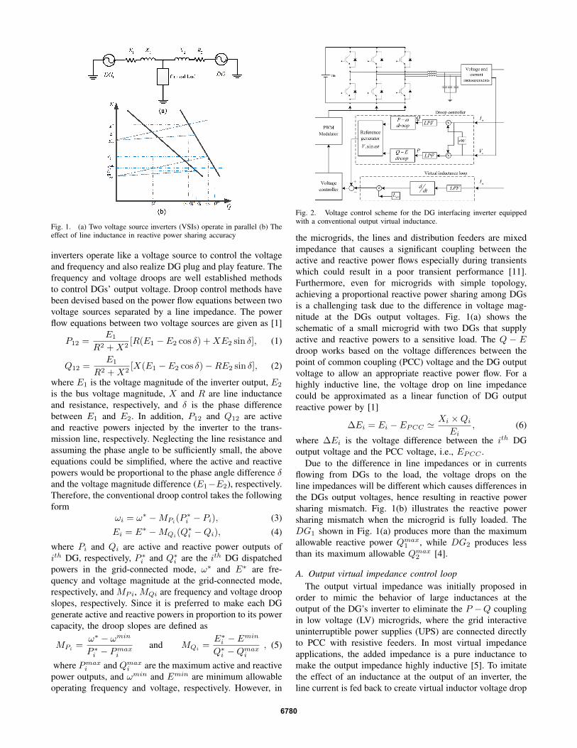
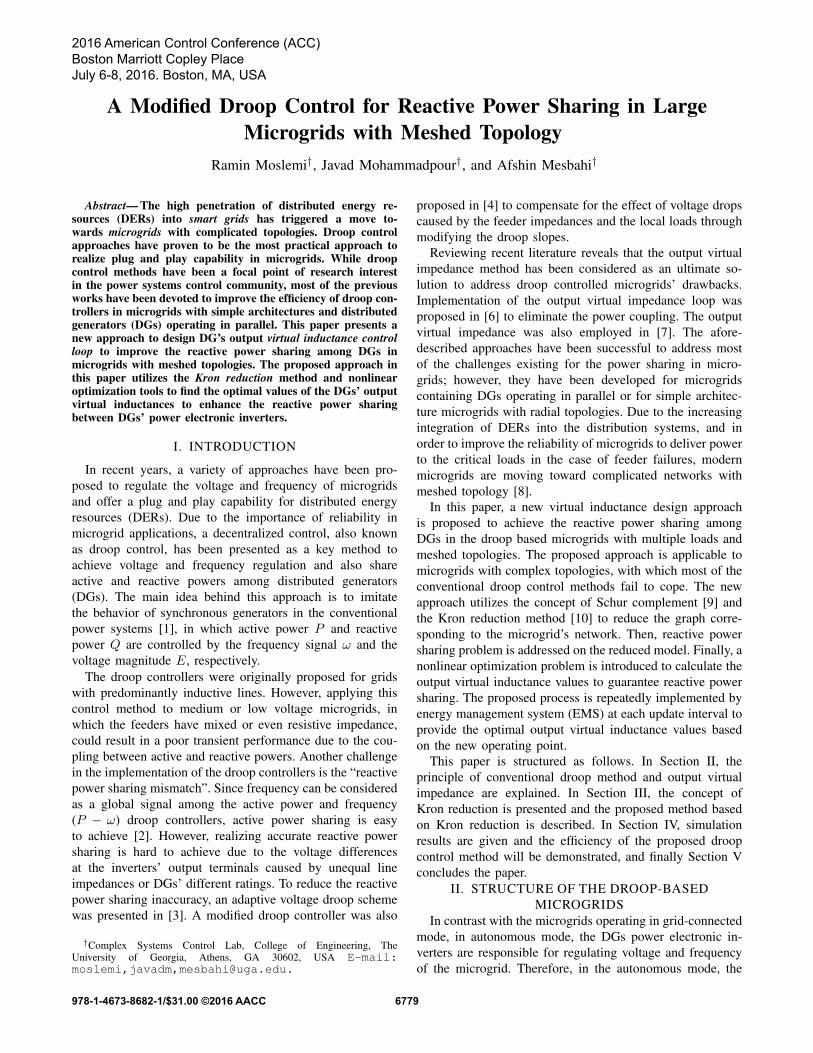
Fig. 1. (a) Two voltage source inverters (VSIs) operate in parallel (b) Theeffect of line inductance in reactive power sharing accuracy
inverters operate like a voltage source to control the voltageand frequency and also realize DG plug and play feature. Thefrequency and voltage droops are well established methodsto control DGs’ output voltage. Droop control methods havebeen devised based on the power flow equations between twovoltage sources separated by a line impedance. The powerflow equations between two voltage sources are given as [1]
P12 =E1
R2 +X2[R(E1 − E2 cos δ) +XE2 sin δ], (1)
Q12 =E1
R2 +X2[X(E1 − E2 cos δ)−RE2 sin δ], (2)
where E1 is the voltage magnitude of the inverter output, E2
is the bus voltage magnitude, X and R are line inductanceand resistance, respectively, and δ is the phase differencebetween E1 and E2. In addition, P12 and Q12 are activeand reactive powers injected by the inverter to the trans-mission line, respectively. Neglecting the line resistance andassuming the phase angle to be sufficiently small, the aboveequations could be simplified, where the active and reactivepowers would be proportional to the phase angle difference δand the voltage magnitude difference (E1−E2), respectively.Therefore, the conventional droop control takes the followingform
ωi = ω∗ −MPi(P∗i − Pi), (3)
Ei = E∗ −MQi(Q∗i −Qi), (4)
where Pi and Qi are active and reactive power outputs ofith DG, respectively, P ∗i and Q∗i are the ith DG dispatchedpowers in the grid-connected mode, ω∗ and E∗ are fre-quency and voltage magnitude at the grid-connected mode,respectively, and MPi, MQi are frequency and voltage droopslopes, respectively. Since it is preferred to make each DGgenerate active and reactive powers in proportion to its powercapacity, the droop slopes are defined as
MPi =ω∗ − ωmin
P ∗i − Pmaxi
and MQi =E∗i − Emin
Q∗i −Qmaxi
, (5)
where Pmaxi and Qmaxi are the maximum active and reactivepower outputs, and ωmin and Emin are minimum allowableoperating frequency and voltage, respectively. However, in
Fig. 2. Voltage control scheme for the DG interfacing inverter equippedwith a conventional output virtual inductance.
the microgrids, the lines and distribution feeders are mixedimpedance that causes a significant coupling between theactive and reactive power flows especially during transientswhich could result in a poor transient performance [11].Furthermore, even for microgrids with simple topology,achieving a proportional reactive power sharing among DGsis a challenging task due to the difference in voltage mag-nitude at the DGs output voltages. Fig. 1(a) shows theschematic of a small microgrid with two DGs that supplyactive and reactive powers to a sensitive load. The Q − Edroop works based on the voltage differences between thepoint of common coupling (PCC) voltage and the DG outputvoltage to allow an appropriate reactive power flow. For ahighly inductive line, the voltage drop on line impedancecould be approximated as a linear function of DG outputreactive power by [1]
∆Ei = Ei − EPCC 'Xi ×QiEi
, (6)
where ∆Ei is the voltage difference between the ith DGoutput voltage and the PCC voltage, i.e., EPCC .
Due to the difference in line impedances or in currentsflowing from DGs to the load, the voltage drops on theline impedances will be different which causes differences inthe DGs output voltages, hence resulting in reactive powersharing mismatch. Fig. 1(b) illustrates the reactive powersharing mismatch when the microgrid is fully loaded. TheDG1 shown in Fig. 1(a) produces more than the maximumallowable reactive power Qmax1 , while DG2 produces lessthan its maximum allowable Qmax2 [4].
A. Output virtual impedance control loopThe output virtual impedance was initially proposed in
order to mimic the behavior of large inductances at theoutput of the DG’s inverter to eliminate the P −Q couplingin low voltage (LV) microgrids, where the grid interactiveuninterruptible power supplies (UPS) are connected directlyto PCC with resistive feeders. In most virtual impedanceapplications, the added impedance is a pure inductance tomake the output impedance highly inductive [5]. To imitatethe effect of an inductance at the output of an inverter, theline current is fed back to create virtual inductor voltage drop
6780

that is then subtracted from the reference voltage (output ofthe droop controller) to produce the final voltage reference,which should be tracked by voltage and current controllers.Fig. 2 shows a DG controlled by droop controllers along withoutput virtual inductance loop responsible for mimicking thebehavior of a real inductor located exactly at the inverter’soutput. For multiple DGs operating in parallel (see Fig. 1(a)),adding a virtual inductance at the inverters output leads toan increase in total inductance Lti = Lli +Lviri , where Lli isthe line or feeder inductance, and hence, the power couplingwould be diminished. In addition, if Lviri ’s are selected suchthat all the Lti’s become equal, then the reactive powersharing is achieved.
III. REACTIVE POWER SHARING INMICROGRIDS WITH A COMPLEX TOPOLOGY
In this section, a new approach is proposed for the designof output virtual inductances to improve reactive powersharing among DGs when the droop controllers are usedin the microgrids with complex topologies. To analyze thereactive power sharing in meshed microgrids, we proposeto use the so-called Kron reduction (also known as ward-equivalent [12]) method. Kron reduction is a powerful tool incircuit analysis and related applications employed to obtainlower dimensional electrically-equivalent circuits. Through-out this section, the notation presented in [10] is employedto establish the proposed method of this paper for reactivepower sharing in microgrids with complex topology.
An autonomous microgrid with n buses and l lines isconsidered here represented by an undirected, connected andweighted graph G = (In, ε, A), where In = 1, ..., n is thenode set set and ε is the edge set. Also, the set of DG nodes(nodes which connect the DGs to the coupling inductance) isdenoted by α ⊆ In with the cardinality of |α| and A ∈ Rn×nis the adjacency matrix which is symmetric and irreducible.
Aij =
1
xij+xviriif i 6= j, i ∈ α, j ∈ In \ α , i, j ∈ ε
1xij
if i, j ∈ In \ α, i, j ∈ ε(7)
where xij , xii and xviri are the line inductance, reactive loadand DGs’ virtual inductance value, respectively. A positiveoff-diagonal element Aij induces a weighted edge i, j ∈ εrepresenting the susceptance of the line that connects busi to bus j, and a positive diagonal element Aii induces aweighted self-loop i, i ∈ ε representing the susceptance ofthe reactive load located at bus i. The Laplacian matrix Lcorresponding to the graph G is defined as
Lij =
−Aij if i 6= j
n∑k=1,k 6=i
Aik if i = j.(8)
A loopy Laplacian matrix is defined as Q(A) = Q , L +diag(Aiini=1) ∈ Rn×n or
Qij =
−Aij if i 6= jn∑k=1
Aik if i = j.(9)
Let Q[α, α] denote the sub-matrix of Q obtained by takingthe first |α| rows and columns, and define the shorthandsQ[α, α) = Q[α, In \ α], Q(α, α] = Q[In \ α, α] andQ(α, α) = Q[In \α, In \α]. Without the loss of generality,the graph could be arranged so that the relationship betweenthe DGs’ current injections I[α] = [iDG1
, . . . , iDG|α| ]T , the
DGs’ output voltages V[α] = [VDG1 , . . . , VDG|α| ]T and other
buses’ voltages V(α) = [V|α|+1, . . . , Vn]T is represented as[I[α]
0
]= −j
[Q[α, α] Q[α, α)
Q(α, α] Q(α, α)
][V[α]
V(α)
], (10)
where j =√−1. The (|α| × |α|)-dimensional Kron-reduced
matrix Qred is defined as the Schur complement of Q withrespect to the block Q(α, α) or
Qred , Q/Q(α, α)
= Q[α, α]−Q[α, α)Q−1(α, α)Q(α, α].(11)
Lemma 3.1: Consider the microgrid network representedby the adjacency matrix (7), and assume that all DG buses areboundary nodes, i.e., will be preserved after applying Kronreduction, and that all other buses are considered as interiornodes, i.e., those nodes that will be eliminated. Then, thefollowing statements are true:(a) The Kron reduced matrix Qred exists and is a strictlyloopy Laplacian matrix.(b) All the nodes in the corresponding reduced graph haveself loops.
Proof: Since the adjacency matrix is a symmetricirreducible matrix, so will have the corresponding loopyLaplacian matrix Q. Now, since Q is a symmetric irreducibleloopy Laplacian matrix, Qred exists, based on Lemma II.1-1 in [10]. In general, there exists at least one local loadin microgrids, and hence Q corresponding to the microgridnetwork is always strictly loopy. According to Lemma II.1-2in [10], Qred is strictly loopy since Q is strictly loopy, andthis completes the proof of statement (a).
Suppose without the loss of generality that the microgridnetwork Q are connected. Therefore, between two nodesi, j ∈ α, there is a path that passes through the nodesbelonging to (In \α)∪i, j. Consequently, it is concludedthat each pair of nodes in Qred is connected by an edgebased on Theorem III.4-1 in [10]. Also, the connectivity ofQ implies that there is a path from all i ∈ α to a loopyinterior node j ∈ In\α. Therefore, according to TheoremIII.4-2 in [10], each node in the reduced graph Qred has aself loop, and this completes the proof for statement (b).
The above lemma implies that instead of the original(possibly large ) microgrid, we can study the reactive powersharing on its equivalent reduced network. The adjacencymatrix associated with the microgrid’s reduced model Aredis defined as
Ared , −Qred + diag(|α|∑
j=1,j 6=i
Qredij|α|i=1). (12)
Based on Lemma 3.1, in reduced model all DGs wouldhave local loads. As an illustrative example, Fig. 3(a) shows
6781
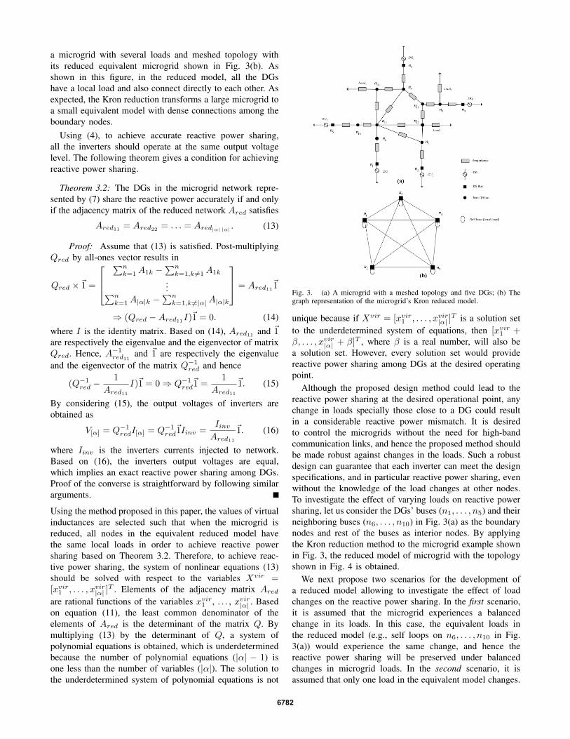
a microgrid with several loads and meshed topology withits reduced equivalent microgrid shown in Fig. 3(b). Asshown in this figure, in the reduced model, all the DGshave a local load and also connect directly to each other. Asexpected, the Kron reduction transforms a large microgrid toa small equivalent model with dense connections among theboundary nodes.
Using (4), to achieve accurate reactive power sharing,all the inverters should operate at the same output voltagelevel. The following theorem gives a condition for achievingreactive power sharing.
Theorem 3.2: The DGs in the microgrid network repre-sented by (7) share the reactive power accurately if and onlyif the adjacency matrix of the reduced network Ared satisfies
Ared11 = Ared22 = . . . = Ared|α| |α| . (13)
Proof: Assume that (13) is satisfied. Post-multiplyingQred by all-ones vector results in
Qred ×~1 =
∑nk=1A1k −
∑nk=1,k 6=1A1k
...∑nk=1A|α|k −
∑nk=1,k 6=|α|A|α|k
= Ared11~1
⇒ (Qred −Ared11I)~1 = 0. (14)where I is the identity matrix. Based on (14), Ared11 and ~1are respectively the eigenvalue and the eigenvector of matrixQred. Hence, A−1red11 and ~1 are respectively the eigenvalueand the eigenvector of the matrix Q−1red and hence
(Q−1red −1
Ared11I)~1 = 0⇒ Q−1red
~1 =1
Ared11~1. (15)
By considering (15), the output voltages of inverters areobtained as
V[α] = Q−1redI[α] = Q−1red~1Iinv =
IinvAred11
~1. (16)
where Iinv is the inverters currents injected to network.Based on (16), the inverters output voltages are equal,which implies an exact reactive power sharing among DGs.Proof of the converse is straightforward by following similararguments.
Using the method proposed in this paper, the values of virtualinductances are selected such that when the microgrid isreduced, all nodes in the equivalent reduced model havethe same local loads in order to achieve reactive powersharing based on Theorem 3.2. Therefore, to achieve reac-tive power sharing, the system of nonlinear equations (13)should be solved with respect to the variables Xvir =[xvir1 , . . . , xvir|α| ]
T . Elements of the adjacency matrix Aredare rational functions of the variables xvir1 , . . . , xvir|α| . Basedon equation (11), the least common denominator of theelements of Ared is the determinant of the matrix Q. Bymultiplying (13) by the determinant of Q, a system ofpolynomial equations is obtained, which is underdeterminedbecause the number of polynomial equations (|α| − 1) isone less than the number of variables (|α|). The solution tothe underdetermined system of polynomial equations is not
Fig. 3. (a) A microgrid with a meshed topology and five DGs; (b) Thegraph representation of the microgrid’s Kron reduced model.
unique because if Xvir = [xvir1 , . . . , xvir|α| ]T is a solution set
to the underdetermined system of equations, then [xvir1 +β, . . . , xvir|α| + β]T , where β is a real number, will also bea solution set. However, every solution set would providereactive power sharing among DGs at the desired operatingpoint.
Although the proposed design method could lead to thereactive power sharing at the desired operational point, anychange in loads specially those close to a DG could resultin a considerable reactive power mismatch. It is desiredto control the microgrids without the need for high-bandcommunication links, and hence the proposed method shouldbe made robust against changes in the loads. Such a robustdesign can guarantee that each inverter can meet the designspecifications, and in particular reactive power sharing, evenwithout the knowledge of the load changes at other nodes.To investigate the effect of varying loads on reactive powersharing, let us consider the DGs’ buses (n1, . . . , n5) and theirneighboring buses (n6, . . . , n10) in Fig. 3(a) as the boundarynodes and rest of the buses as interior nodes. By applyingthe Kron reduction method to the microgrid example shownin Fig. 3, the reduced model of microgrid with the topologyshown in Fig. 4 is obtained.
We next propose two scenarios for the development ofa reduced model allowing to investigate the effect of loadchanges on the reactive power sharing. In the first scenario,it is assumed that the microgrid experiences a balancedchange in its loads. In this case, the equivalent loads inthe reduced model (e.g., self loops on n6, . . . , n10 in Fig.3(a)) would experience the same change, and hence thereactive power sharing will be preserved under balancedchanges in microgrid loads. In the second scenario, it isassumed that only one load in the equivalent model changes.
6782

Fig. 4. The graph representation of the reduced microgrid with five DGs,in which DG buses (outer nodes) and their neighboring buses (inner nodes)are considered as boundary nodes.
It is worth noting that this is a truly pessimistic scenario inmicrogrids since an increase even in one load will cause anincrease in all other ones in the equivalent reduced model.The proposed load change is the same with the existence oflocal loads causing a considerable reactive power mismatchin DGs parallel operation as described in [4]. To minimizethe effect of this load change on the reactive power sharing,the effective inductances between all DGs and the proposedload should be as close as possible to each other for all thepossible cases. It is noted that the edges connecting innernodes vary by changing microgrid loads, and hence the effectof the inner edges variations on effective inductances shouldbe minimized. To achieve this, in the proposed method, thevalues of virtual inductance should be maximized. It shouldbe also considered that the voltage differences between DGbuses and load buses should be maintained within an accept-able range. Therefore, to cope with unbalanced changes inmicrogrid loads, we modify the design problem as findingthe solution to the following optimization problem
maximizeXvir
|α|∑i=1
xviri
subject to: equations in (13) (17)and xmini ≤ xij + xviri ≤ xmaxi for i ∈ α, i, j ∈ ε,
where the inequality constraints guarantee stability andpower quality of the microgrid. The above optimizationproblem can be solved since the objective function is linearand equation (13) is an underdetermined system of poly-nomial equations [13]. By applying the proposed method,an acceptable power sharing among DGs in microgridseven with complicated topologies could be achieved. It isnoted that the values of virtual output inductances would beupdated at every energy management system (EMS) updateinterval. This means that EMS, which has a slower timescale compared to the droop controllers, carries out thecalculations involved in the proposed method at every updateinterval based on the values of loads and microgrid currenttopology (in the case of the DGs or lines outages). Therefore,the proposed method is sufficiently accurate to cope with theload changes around the operating points, based on which theoutput virtual inductance design had been done.
IV. SIMULATION RESULTS AND DISCUSSIONTo examine the efficacy of the proposed approach to im-
prove the reactive power sharing in microgrids with meshedtopology, a microgrid with three similar DGs, as shown inFig. 5 is simulated in MATLAB/Simulinkr. The DGs’droop parameters and loads’ characteristics are shown inTable I. It is noted that the dynamics of power electronicsinverters’ switching is neglected here, and it is assumed thatthe inverters can track the voltage references instantaneously.
TABLE ITHE MICROGRID’S SIMULATION PARAMETERS
Parameter ValueNominal voltage (rms) 104VDGs minimum voltage (rms) 98VDGs maximum active power 500WDGs maximum reactive power 500VarDispatched powers in grid-connected mode 175W, 75Varload1 (active and reactive) 9Ω, 50mHload2 (active and reactive) 9Ω, 100mHLines’ resistance 0.3Ω
Fig. 5. Topology of the test microgrid with three DGs and two loads.
In the first simulation, all DGs are assumed to have thesame output virtual inductance of 2mH . At t = 3sec,load1 is doubled and at t = 5sec, load2 is doubled. Thereactive power outputs of all three DGs are shown in Fig.6. As shown in this figure, there is a large reactive powermismatch between DGs especially between DG1 and DG3.Also, the reactive power sharing mismatch becomes worseas the loads increase. In the second simulation, the output
1 2 3 4 5 6 7200
250
300
350
400
450
500
Time (seconds)
DG
’s o
utpu
t rea
ctiv
e po
wer
s (V
ar)
DG1DG2DG3
Fig. 6. The DGs’ output reactive powers using conventional design with2mH output virtual inductances for all DGs.
6783

virtual inductances are determined by solving the algebraicequations in (13). The inductances of Lvir1 = 1.293mH ,Lvir2 = 1.059mH and Lvir3 = 0.5mH are one set of solutionto (13). These values are then used to design the virtualoutput inductances. Fig. 7 illustrates the DGs’ output reactivepower for the system that uses the designed inductancevalues. As shown in this figure, at the operating point thethree DGs produce almost the same amount of reactive power(231V ar). It is noted that the small difference betweenthe DGs’ reactive power is because of the effect of activepower loads flowing through the transmission lines. After anincrease in load1 at t = 3sec, there is a noticeable mismatchbetween the output reactive powers of DGs, which is due tothat only the load close to DG1 has been increased. Afteran increase in load2, the three DGs provide a much closerreactive power as expected.
1 2 3 4 5 6 7200
250
300
350
400
450
500
Time (seconds)
DG
s’ o
utpu
t rea
ctiv
e po
wer
s (V
ar)
DG1DG2DG3
Fig. 7. The DGs’ output reactive powers obtained by solving the algebraicequations in (13).
For the last simulation, the virtual inductance values areobtained by solving the optimization problem in (17). Byapplying the proposed method, the virtual reactances areobtained as Lvir1 = 3.398mH , Lvir2 = 3.148mH and Lvir3 =2.580mH . Fig. 8 illustrates the output reactive powers forthe same load changes as in the second simulation using thedetermined inductances. Comparing this figure with Fig. 7shows that although both methods are successful to achievean acceptable reactive power sharing at the operating pointand balanced increase in loads, applying the latter approachwould result in a better reactive load sharing when only oneload is increased. Therefore, the proposed approach is ableto yield a reactive power sharing among DGs equally evenif the microgrid experiences severe unbalanced load increase(only load1 was doubled at t = 3sec).
As the configuration of a microgrid, its participating DGsand operating points change over time, the values of virtualinductances should be updated by the energy managementsystem (EMS) at each update interval (several minutes); wepropose to do this through solving the optimization problemin (17) for the updated microgrid configuration.
V. CONCLUDING REMARKS
This paper has addressed the reactive power sharing chal-lenge among distributed generators (DGs). The proposedapproach utilizes the design of output virtual inductances
1 2 3 4 5 6 7200
250
300
350
400
450
500
Time (seconds)
DG
s’ o
utpu
t rea
ctiv
e po
wer
s (V
ar)
DG1DG2DG3
Fig. 8. The DGs’ output reactive powers determined by solving theoptimization problem in (17).
and exploits the Kron reduction technique to investigatereactive power sharing on the reduced, simplified model.The proposed approach is then robustified against microgridunbalanced loads variations. The simulation results haveconfirmed the efficiency the proposed approach to preservereactive power sharing under severe unbalanced load changesin microgrids with meshed topology.
REFERENCES
[1] M. C. Chandorkar, D. M. Divan, and R. Adapa, “Control of parallelconnected inverters in standalone AC supply systems,” IEEE Trans.Ind. Appl., vol. 29, no. 1, 1993, pp. 136-143.
[2] J. Simpson-Porco, F. Dorfler, and F. Bullo, “Synchronization andpower sharing for droop controlled inverters in islanded microgrids,”Automatica., vol. 49, 2013, pp. 2603-2611.
[3] E. Rokrok and M. E. H. Golshan, “Adaptive voltage droop methodfor voltage source converters in an islanded multibus microgrid,” IETGeneration, Transmission and Distribution., vol. 4, no. 5, 2010, pp.562-578.
[4] Y. Li and C. N. Kao, “An accurate power control strategy for powerelectronics-interfaced distributed generation units operating in a low-voltage multi bus microgrid,” IEEE Trans. Power Electron., vol. 24,no. 12, 2015, pp. 2977-2988.
[5] R. Moslemi and J. Mohammadpour , “Accurate reactive power controlof autonomous microgrids using an adaptive virtual inductance loop,”Electric Power Systems Research, vol. 129, 2015, pp. 142-149.
[6] J.M. Guerrero, L.G, Vicuna, J. Matas, M. Castilla, and J. Miret,“Output impedance design of parallel-connected UPS inverters withwireless load sharing control,” IEEE Trans. Ind. Electron., vol. 52,no. 4, 2005, pp. 1126-1135.
[7] J. He, Y. W. Li, J. M. Guerrero, F. Blaabjerg, and J. C. Vasquez, “Anislanding microgrid power sharing approach using enhanced virtualimpedance control scheme,” IEEE Trans. Ind. Electron., vol. 28, no.11, 2013, pp. 5272-5282.
[8] S. Riverso, F. Sarzo, and G. Ferrari-Trecate, “Plug-and-play voltageand frequency control of islanded microgrids with meshed topology,”IEEE Trans. Smart Grid., vol. PP, no. 99, 2015, pp. 1-9.
[9] F. Zhang, The Schur complement and its applications, Springer,NewYork, NY; 2005.
[10] F. Dorfler and F. Bullo, “Kron reduction of graphs with applicationsto electrical networks,” IEEE Trans. Circuits Sys. I: Reg. Papers., vol.60, no. 1, 2013, pp. 150-163.
[11] Y. R. Mohamed and M. Ashabani, “Adaptive decentralized droopcontroller to preserve power sharing stability of paralleled invertersin distributed generation microgrids,” IEEE Trans. Power Electron.,vol. 23, no. 6, 2008, pp. 2806-2816.
[12] J. B. Ward, “Equivalent circuits for power-flow studies,” Trans. Am.Inst. Electr. Eng., vol. 68, no. 1, 2009, pp. 373-382.
[13] S. Boyd and L. Vandenberghe. Convex optimization, Cambridge Uni-versity Press, 2004.
6784


![Removal of Reactive Dye by Adsorption over Chemical Pretreatment … · reactive dyes are used for dyeing wool, cotton, nylon, silk, and modified acrylics [11]. Discharging dyes into](https://img.pdfslide.net/doc/110x75/5eaa60430b38795d226748d4/removal-of-reactive-dye-by-adsorption-over-chemical-pretreatment-reactive-dyes-are.jpg)