Embed Size (px)
Citation preview
1538
A Modified Method for IEEE TRANSACTIONS ON ELECTRON DEVICES, VOL. 38, NO. 6, JUNE
~
1991
Producing Carbon-Loaded Vacuum-Compatible Microwave Absorbers from
a Porous Ceramic J . P. Calame and Wesley G. Lawson, Member, IEEE
Abstract-The well-established procedure for producing mi- crowave absorbers by carbon loading a porous ceramic has been modified to enhance the cleanliness of the final product and to improve the controllability of the loss tangent. The changes in- clude soaking the ceramics in an acid bath to leach out unde- sirable metal oxides and a multiple-step carbonization using both carbon dioxide and hydrogen firings. These modifications allow the use of an aluminum silicate material known as Aremcolox" 502-1100' as a starting material for absorbers in critical applications, such as a system with an osmium-coated dispenser cathode. The processing steps are described in detail and their relevance to the development of a high-peak-power X-band gyroklystron is discussed. Representative values of the complex dielectric constants at 9.9 GHz for various carbon con- tents are presented.
I. INTRODUCTION OR approximately the last 45 years, a technique for F producing vacuum-compatible microwave absorbers
by the carbon loading of a machinable, porous ceramic has been widely applied in the construction of microwave tubes. The details of the procedure have traditionally been passed from worker to worker in an informal fashion, and it was in this manner that the authors learned of the tech- nique [ l ] . The essential steps involved forming the ce- ramic into the desired shape, soaking the ceramic in a sugar solution, and ultimately converting the sugar to car- bon in a hydrogen furnace. Over the past decade, these materials have been largely replaced by products such as Ceralloy'" [2], which is a hot-pressed, nonporous mixture of ceramics such as alumina with silicon carbide.*
Nonporous ceramic-Sic materials have vastly lower outgassing rates and superior mechanical properties com- pared with porous, carbon-loaded ceramics. In spite of these advantages, there are still circumstances where the carbon-loaded materials are preferable. For example, in microwave tube research it is often necessary to experi-
Manuscript received July 10, 1990; revised December4, 1990. This work was supported by the U.S. Department of Energy and the University of Maryland Designated Research Initiative Funds. The review of this paper was arranged by Associate Editor R. Temkin.
The authors are with the Laboratory for Plasma Research, University of Maryland, College Park, MD 20742.
IEEE Log Number 9143749. 'Aremcolox 502-1 100 is a trademark of Aremco Products, Inc. 'Ceralloy is a trademark of Ceradyne, Inc.
ment with various arrangements of lossy material, by trial and error, to suppress unwanted parasitic oscillations. The cost and procurement time for nonporous ceramic-Sic mixtures makes this process very difficult. By contrast, various configurations of carbon-loaded ceramic can usu- ally be fabricated in-house quickly and with low cost. Any outgassing problems are usually minor since most re- search tubes are continuously pumped. Another related advantage of the carbon-loaded ceramics is the ability to adjust the loss of a particular component by varying the carbon content. Finally, the carbon-loaded p.orous ce- ramics have a lower real part of the dielectric constant than a ceramic-Sic material with the same loss tangent. This is of benefit when the lossy material is placed inside a microwave cavity to reduce the quality factor, because the frequency shift will be less sensitive to the dimensions of the absorber. A lower dielectric constant is also helpful in reducing reflections at the vacuum/ceramic interface.
The high peak power X-band gyroklystron which is presently undergoing initial operation at the University of Maryland makes wide use of porous carbon-loaded ce- ramics. The input cavity of this tube operates in the TEol circular mode at 9.85 GHz and contains a thin annular ring of lossy dielectric on the downstream endwall to maintain the quality factor at 175. Additional lossy ma- terial is present in the form of alternating dielectric and metal rings of various sizes in the tapered region between the gun and the input cavity.
Our electron gun uses an osmium-coated barium dis- penser cathode which is very sensitive to contaminants and needs a vacuum below 1 x lop8 torr to operate well. A thorough search for machinable, slightly porous ce- ramic materials that would be compatible with the cathode was undertaken. Some of the ceramic materials used in the past for producing carbon-loaded absorbers are no longer available as stock items, while others such as AL- 1009'M,3 Alsimag'" 222,4 and Alfrax" have porosities in excess of 12% [3], which may cause too great a gas load for our application. An aluminum silicate material known as Aremcolox'" 502-1 100 [4] has been used previously in making absorbers by other workers, and it appeared to be
3A1-1009 is a trademark of Western Gold and Platinum Works. 4Alsimag 222 is a trademark of 3M Co. 5Alfrax is a trademark of Carborundum Co.
0018-9383/91/0600-1538$01 .OO 0 1991 IEEE
. .
CALAME AND LAWSON: METHOD FOR PRODUCING MICROWAVE ABSORBERS FROM A POROUS CERAMIC 1539
the ideal material from the standpoint of availability, ma- chinability, porosity, and strength.
The remainder of this paper will describe several mod- ifications to the standard processing procedure which were developed to ensure the compatibility of the final product with our cathode and to enhance controllability of the loss tangent. While most of these additional steps are tailored explicitly to the processing of Aremcolox" 502-1 100, some of the improvements have merit for any suitable base ceramic. Toward the end of this paper representative val- ues of the complex dielectric constant of carbon-loaded AremcoloxTM 502-1 100 in X-band will be presented.
11. DESCRIPTION OF THE PROCESSING STEPS
A. Cutting and Firing The Aremcolox" 502-1 100 ceramic material comes in
a soft, hydrated form in various bulk shapes. After ma- chining with regular tooling and without cutting fluid, the parts are fired in an air furnace according to the manufac- turer's instructions [4]. The result is a hard, rigid material with a porosity of 2 to 5 % . The fired part is about 2% larger in all dimensions than the size before firing. It is advisable to make a practice piece first as the expansion figure is somewhat different for each lot of material.
B. Chemical Analysis Samples of both unfired and fired material have been
chemically analyzed at our laboratory to determine the type and quantities of impurities. To accomplish this, the materials were powdered and put into suspension in con- centrated (37%) hydrochloric acid. After 3 h of stirring the leachant was separated from the insoluble aluminum silicate suspension by filtration. The resulting liquid was boiled to remove the acid, diluted with deionized water, and subjected to chemical separation and gravimetric analysis. In all cases the main impurities were iron and chromium, which presumably exist as Fe203 and Cr203 in the fired material. The typical concentrations of these substanfles by weight in the fired ceramic are 2 to 5 % for iron oxide and 0.1 to 0.3 % for chromium oxide. In ad- dition, there are small quantities of arsenic oxide (50-150 ppm), bismuth oxide (25-80 ppm), and a very small quantity of tin oxide (less than 25 ppm). There is consid- erable variation in these trace substances between lots.
The presence of iron, chromium, and tin in the ceramic does not present a problem from the standpoint of cathode contamination, but it can have a negative effect on the control of the carbon content in the finished absorber. For instance, a carbon particle which forms in a region rich in iron oxide will tend to reduce the iron oxide to free iron, and thus carbon will be lost as carbon monoxide or dioxide. Arsenic and bismuth cannot be tolerated in the system because of their high vapor pressures and poison- ing action on a dispenser cathode. Removal of as many impurities as possible is therefore required.
C. Purijication The most obvious way to purify the ceramic is by soak-
ing the fired pieces in a liquid capable of dissolving the impurities without attacking the aluminum silicate base material. Since all of the impurities are either basic or amphoteric oxides, an acid would be the most promising choice. However, all traces of acid must be completely removed from the porous ceramic prior to inclusion in a vacuum system, and .this rules out the use of the strong inorganic acids. However, an organic acid containing only carbon,, oxygen, and hydrogen can be totally converted into carbon dioxide and water by firing in an air furnace, eliminating the problem of acid contamination. Initial ex- periments performed with acetic acid did not succeed pre- sumably because acetic acid is very weak @Ka = 4.75) [5] and reacts too slowly with the impurities.
Oxalic acid is a comparatively strong diprotic, organic acid @Kal = 1.23) [5 ] which can be made into moder- ately concentrated solutions in water. A 45 g/1 solution of oxalic acid in water (0.5 M) has a pH of about 1.3 and is capable of removing the arsenic, tin, and bismuth strictly due to its acidity. Furthermore, iron oxide is dis- solved via the formation of an iron oxalate complex ion. Unfortunately, chromium oxide is not attacked by oxalic acid and to date no procedure has been developed to re- move it. This is not a serious problem since the concen- tration of chromium oxide is usually a fraction of a per- cent and it has low vapor pressure.
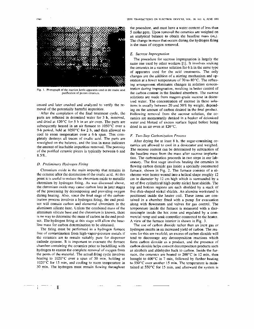
The practical aspects of the purification process are de- scribed below. The previously machined and air-fired ce- ramic pieces are weighed on an analytical balance and placed in a wide-mouthed Pyrex'" reaction kettle fitted with a condenser for refluxing (Fig. 1). TeflonTM7 tape is used to seal the ground glass joints of the apparatus since grease would contaminate the ceramic. A quantity of 0.5 M oxalic acid solution (typically 25-ml acid solution per 1 g of ceramic) is placed in the kettle and the mixture is heated to boiling and maintained there for 24 h. The re- fluxing condenser prevents evaporation of the liquid and allows the purification to proceed unattended. The solu- tion will turn yellow-green due to the dissolution of iron oxide. After cooling, the liquid is removed and the ce- ramic pieces rinsed in deionized water. This sequence of operations is called a cycle. Most ceramic parts can be cleansed of their removable impurities with four to seven cycles, using fresh acid solution each time. This assumes that the parts are cut such that all internal points are no further than 2.5 mm from a surface. Thicker pieces will require a much greater number of cycles and are not rec- ommended. The progress at removing the iron can be monitored by observing the color of the spent acid solu- tion. Since diffusion of the dissolved impurities out of the ceramic is the limiting step in the process, the removal of arsenic, bismuth, and tin proceeds at a rate similar to that of iron. In critical applications, a test part can be pro-
6Pyrex is a trademark of Coming Glass Works. 'Teflon is a trademark of Dupont, Inc.
~
TT IT IEEE TRANSACTIONS ON ELECTRON DEVICES. VOL. 3 8 . NO 6. JUNE 1991 1399
I540 IEEE TRANSACTIONS ON ELECTRON DEVICES, VOL. 38, NO. 6, JUNE 1991
Fig. 1. Photograph of the reaction kettle apparatus used in the oxalic acid purification of porous ceramics.
cessed and later crushed and analyzed to verify the re- moval of the potentially harmful impurities.
. After the completion of the final treatment cycle, the parts are refluxed in deionized water for 3 h, removed, and dried at 120°C for 5 h in an air oven. The parts are subsequently heated in an air furnace to 1050°C over a 9-h period, held at 1050°C for 2 h, and then allowed to cool to room temperature over a 6-h span. This com- pletely destroys all traces of oxalic acid. The parts are reweighed on the balance, and the loss in mass indicates the amount of leachable impurities removed. The porosity of the purified ceramic pieces is typically between 6 and 8.5%.
D. Preliminary Hydrogen Firing
Chromium oxide is the main impurity that remains in the ceramic after the destruction of the oxalic acid. At this point it is useful to reduce the chromium oxide to metallic chromium by hydrogen firing. As was discussed above, the chromium oxide may cause carbon loss in later stages of the processing by decomposing and providing oxygen during heating. Also, since the final stage of the carbon- ization process involves a hydrogen firing, the end prod- uct will contain carbon and elemental chromium in the aluminum silicate base. Unless the combined mass of the aluminum silicate base and the chromium is known, there is no way to determine the mass of carbon in the end prod- uct. The hydrogen firing at this stage will allow the base- line mass for carbon determination to be obtained.
The firing must be performed in a hydrogen furnace free of contamination from high-vapor-pressure metals if the ceramics are to remain suitably pure for dispenser cathode systems. It is important to evacuate the furnace chamber containing the ceramics prior to backfilling with hydrogen to ensure the complete removal of oxygen from the pores of the material. The actual firing cycle involves heating to 1020°C over a span of 50 min, holding at 1020°C for 15 min, and cooling to room temperature in 30 min. The hydrogen must remain flowing throughout
the procedure, and must have a water content of less than 5 molar ppm. Upon removal the ceramics are weighed on an analytical balance to obtain the baseline mass (mb). The change in mass that occurs during the hydrogen firing is the mass of oxygen removed.
E. Sucrose Impregnation The procedure for sucrose impregnation is largely the
same one used by other workers [l] . It involves soaking the ceramics in a sucrose solution for 6 h in the same type of apparatus used for the acid treatments. The only changes are the addition of a stirring mechanism and op- eration at a lower temperature of 70 to 80°C. The reflux- ing arrangement eliminates changes in solution concen- tration during impregnation, resulting in better control of the carbon content in the finished absorbers. The sucrose solutions are made from reagent-grade sucrose in deion- ized water. The concentration of sucrose in these solu- tions is usually between 20 and 50% by weight, depend- ing on the amount of carbon desired in the final product. Following removal from the sucrose solution, the ce- ramics are momentarily dunked in a beaker of deionized water and blotted of excess surface liquid before being dried in an air oven at 120°C.
F. Two-step Carbonization Process After drying for at least 8 h, the sugar-containing ce-
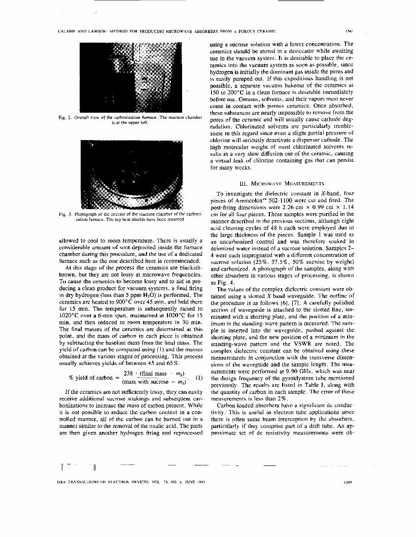
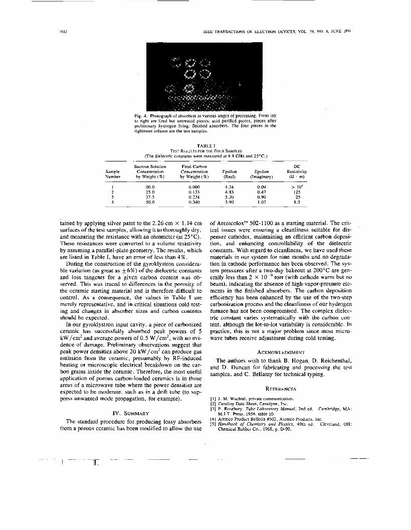
ramics are allowed to cool in a desiccator and weighed. The sucrose content can be determined by subtraction of the baseline mass from the mass after sucrose implanta- tion. The carbonization proceeds in two steps in our lab- oratory. The first stage involves heating the ceramics in flowing carbon dioxide gas inside a specially constructed furnace, shown in Fig. 2. The furnace consists of a ni- chrome wire heater wound into a helical shape roughly 12 cm in diameter by 12 cm high which is surrounded by a set of five cylindrical high-purity nickel heat shields. The top and bottom regions are each shielded by a stack of five disk-shaped nickel shields. An alumina workstand is positioned inside the heater coil. These items are con- tained in a chamber fitted with a pump for evacuation along with flowmeters and valves for gas control. The temperature inside the furnace is measured with a ther- mocouple inside the hot zone and regulated by a com- mercial ramp and soak controller connected to the heater. A view of the furnace interior is shown in Fig. 3.
The use of carbon dioxide rather than an inert gas or hydrogen results in an increased yield of carbon. The rea- sons for this are twofold; an excess of carbon dioxide will tend to discourage any decomposition reactions which form carbon dioxide as a product, and the presence of carbon dioxide helps convert decomposition products such as alcohols and aldehydes back to carbon. Inside the fur- nace, the ceramics are heated to 200°C in 12 min, then brought to 400°C in 7 min, followed by further heating to 550°C over another 15 min. The temperature is main- tained at 550°C for 15 min, and afterward the system is
. , .
CALAME AND LAWSON: METHOD FOR PRODUCING MICROWAVE ABSORBERS FROM A POROUS CERAMIC 1541
Fig. 2. Overall view of the carbonization fumace. The reaction chamber is at the upper left.
Fig. 3 . Photograph of the interior of the reaction chamber of the carboni- zation fumace. The top heat shields have been removed.
allowed to cool to room temperature. There is usually a considerable amount of soot deposited inside the furnace chamber during this procedure, and the use of a dedicated furnace such as the one described here is recommended.
At this stage of the process the ceramics are blackish- brown, but they are not lossy at microwave frequencies. To cause the ceramics to become lossy and to aid in pro- ducing a clean product for vacuum systems, a final firing in dry hydrogen (less than 5 ppm H20) is performed. The ceramics are heated to 900°C over 45 min, and held there for 15 min. The temperature is subsequently raised to 1020°C over a 6-min span, maintained at 1020°C for 15 min, and then reduced to room temperature in 30 min. The final masses of the ceramics are determined at this point, and the mass of carbon in each piece is obtained by subtracting the baseline mass from the final mass. The yield of carbon can be computed using (1) and the masses obtained at the various stages of processing. This process usually achieves yields of between 45 and 65 % .
238 (final mass - mb) (mass with sucrose - mb) *
% yield of carbon = (1)
If the ceramics are not sufficiently lossy, they can easily receive additional sucrose soakings and subsequent car- bonizations to increase the mass of carbon present. While it is not possible to reduce the carbon content in a con- trolled manner, all of the carbon can be burned out in a manner similar to the removal of the oxalic acid. The parts are then given another hydrogen firing and reprocessed
using a sucrose solution with a lower concentration. The ceramics should be stored in a desiccator while awaiting use in the vacuum system. It is desirable to place the ce- ramics into the vacuum system as soon as possible, since hydrogen is initially the dominant gas inside the pores and is easily pumped out. If this expeditious handling is not possible, a separate vacuum bakeout of the ceramics at 150 to 200°C in a clean furnace is desirable immediately before use. Greases, solvents, and their vapors must never come in contact with porous ceramics. Once absorbed, these substances are nearly impossible to remove from the pores of the ceramic and will usually cause cathode deg- radation. Chlorinated solvents are particularly trouble- some in this regard since even a slight partial pressure of chlorine will seriously deactivate a dispenser cathode. The high molecular weight of most chlorinated solvents re- sults in a very slow diffusion out of the ceramic, causing a virtual leak of chlorine containing gas that can persist for many weeks.
111. MICROWAVE MEASUREMENTS
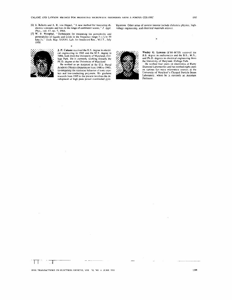
To investigate the dielectric constant in X-band, four pieces of AremcoloxTM 502-1 100 were cut and fired. The post-firing dimensions were 2.26 cm x 0.99 cm X 1.14 cm for all four pieces. These samples were purified in the manner described in the previous sections, although eight acid cleaning cycles of 48 h each were employed due to the large thickness of the pieces. Sample 1 was used as an uncarbonized control and was therefore soaked in deionized water instead of a sucrose solution. Samples 2- 4 were each impregnated with a different concentration of sucrose solution (25%, 37.5%, 50% sucrose by weight) and carbonized. A photograph of the samples, along with other absorbers in various stages of processing, is shown as Fig. 4.
The values of the complex dielectric constant were ob- tained using a slotted X-band waveguide. The outline of the procedure is as follows [6], [7]. A carefully polished section of waveguide is attached to the slotted line, ter- minated with a shorting plate, and the position of a min- imum in the standing-wave pattern is measured. The sam- ple is inserted into the waveguide, pushed against the shorting plate, and the new position of a minimum in the standing-wave pattern and the VSWR are noted. The complex dielectric constant can be obtained using these measurements in conjunction with the transverse dimen- sions of the waveguide and the sample length. The mea- surements were performed at 9.90 GHz, which was near the design frequency of the gyroklystron tube mentioned previously. The results are listed in Table I , along with the quantity of carbon in each sample. The error of these measurements is less than 2 % .
Carbon-loaded absorbers have a significant dc conduc- tivity. This is useful in electron tube applications since there is often some beam interception by the absorbers, particularly if they comprise part of a drift tube. An ap- proximate set of dc resistivity measurements were ob-
- __ __ ~- -. - rr IT IEEE TRANSACTIONS ON ELECTRON DEVICES. VOL 78. NO 6. JUNE 1991
1542 IEEE TRANSACTIONS ON ELECTRON DEVICES, VOL. 38. NO. 6, JUNE 1991
Fig. 4 . Photograph of absorbers in various stages of processing. From left to right are fired but untreated pieces; acid purified pieces; pieces after preliminary hydrogen firing; finished absorbers. The four pieces in the rightmost column are the test samples.
TABLE I TEST RESULTS FOR THE FOUR SAMPLES
(The dielectric constants were measured at 9.9 GHz and 25°C.)
Sucrose Solution Final Carbon DC Sample Concentration Concentration Epsilon Epsilon Resistivity Number by Weight (%) by Weight (%) (Real) (Imaginary) (Q . m)
1 00.0 0.000 4.34 0.09 > IO6 2 25.0 0.133 4.83 0.47 125 3 31.5 0.234 5.30 0.90 25 4 50.0 0.340 5.90 1.07 8.5
iained by applying silver paint to the 2.26 cm x 1.14 cm surfaces of the test samples, allowing it to thoroughly dry, and measuring the resistance with an ohmmeter (at 25°C). These resistances were converted to a volume resistivity by assuming a parallel-plate geometry. The results, which are listed in Table I, have an error of less than 4 % .
During the construction of the gyroklystron considera- ble variation (as great as *6%) of the dielectric constants and loss tangents for a given carbon content was ob- served. This was traced to differences in the porosity of the ceramic starting material and is therefore difficult to control. As a consequence, the values in Table I are merely representative, and in critical situations cold test- ing and changes in absorber sizes and carbon contents should be expected.
In our gyroklystron input cavity, a piece of carbonized ceramic has successfully absorbed peak powers of 5 kW/cm2 and average powers of 0.5 W/cm2, with no evi- dence of damage. Preliminary observations suggest that peak power densities above 20 kW /cm2 can produce gas
of AremcoloxTM 502-1 100 as a starting material. The crit- ical issues were ensuring a cleanliness suitable for dis- penser cathodes, maintaining an efficient carbon deposi- tion, and enhancing controllability of the dielectric constants. With regard to cleanliness, we have used these materials in our system for nine months and no degrada- tion in cathode performance has been observed. The sys- tem pressures after a two-day bakeout at 200°C are gen- erally less than 2 X torr (with cathode warm but no beam), indicating the absence of high-vapor-pressure ele- ments in the finished absorbers. The carbon deposition efficiency has been enhanced by the use of the two-step carbonization process and the cleanliness of our hydrogen furnace has not been compromised. The complex dielec- tric constant varies systematically with the carbon con- tent, although the lot-to-lot variability is considerable. In practice, this is not a major problem since most micro- wave tubes receive adjustment during cold testing.
ACKNOWLEDGMENT emission from the ceramic, presumably by &-induced The authors wish to thank B. Hogan, D. Reichenthal, heating or microscopic electrical breakdown on the car- bon grains inside the ceramic. Therefore, the most useful application of porous carbon-loaded ceramics is in those
and D. Duncan for fabricating and processing the test samples, and c. Bellamy for technical typing.
areas of a microwave tube where the power densities are expected to be moderate, such as in a drift tube (to sup- REFERENCES press unwanted mode propagation, for example). [ l ] J . M. Wachtel, private communication.
[2] Ceralloy Data Sheet, Ceradyne, Inc. [3] F. Rosebury, Tube Laboratory Manual, 2nd ed. Cambridge, MA:
IV. SUMMARY M.I.T. Press, 1956, table 10.
The standard procedure for producing lossy absorbers [41 Aremco Product Bulletin #502, Aremco Products, Inc. 151 Handbook of Chemistry and Physics, 49th ed. Cleveland, OH:
from a porous ceramic has been modified to allow the use Chemical Rubber Co., 1968, p. D-90.
~
I T
CALAME AND LAWSON: METHOD FOR PRODUCING MICROWAVE ABSORBERS FROM A POROUS CERAMIC I543
[61 S . Roberts and A. R. von Hippel, “A new method for measuring di- electric constants and loss in the range of centimeter waves,” J . Appl. Phys., vol. 17, no. 7 , 1946.
[71 W . B . Westphal, “Techniques for measuring the permittivity and permeability of liquids and solids in the frequency range 3 c / s to 50 kmc/s,” Tech. Rep. XXXVI, Lab. for Insulation Res., M.I.T., July 1950.
klystrons. Other areas of current interest include dielectric physics, high- voltage engineering, and electrical materials science.
*
* J. P. Calame received the B.S . degree in electri- cal engineering in 1985 and the M.S. degree in 1986, both from the University of Maryland, Col- lege Park. He is currently working towards the Ph.D. degree at the University of Maryland.
He worked as an Assistant at the U.S. Naval Academy Physics Department from 1980 to 1985, investigating the electrical behavior of ionic crys- tals and ion-conducting polymers. His graduate research from 1985 to the present involves the de- velopment of high peak power overmoded gyro-
Wesley G. Lawson (S’84-M’85) received the B.S. degree in mathematics and the B.S., M.S., and Ph.D. degrees in electrical engineering from the University of Maryland, College Park.
He worked four years on electronics at Harry Diamond Laboratories and has worked eight years on various fast-wave microwave sources at the University of Maryland’s Charged Particle Beam Laboratory, where he is currently an Assistant Professor.
- - ~ _ _ _
IEEE TRANSACTIONS ON ELECTRON DEVICES. VOL 78. NO 6. JUNE 1991