Embed Size (px)
Citation preview

A Modular Network Layer for Sensornets
Cheng Tien Ee∗, Rodrigo Fonseca∗, Sukun Kim∗, Daekyeong Moon∗, Arsalan Tavakoli∗,David Culler∗†, Scott Shenker∗‡, Ion Stoica∗
AbstractAn overall sensornet architecture would help tame the in-creasingly complex structure of wireless sensornet soft-ware and help foster greater interoperability between dif-ferent codebases. A previous step in this direction isthe Sensornet Protocol (SP), a unifying link-abstractionlayer. This paper takes the natural next step by proposinga modular network-layer for sensornets that sits atop SP.This modularity eases implementation of new protocolsby increasing code reuse, and enables co-existing proto-cols to share and reduce code and resources consumedat run-time. We demonstrate how current protocols canbe decomposed into this modular structure and show thatthe costs, in performance and code footprint, are minimalrelative to their monolithic counterparts.
1 IntroductionThe field of wireless sensornets (hereafter, sensornets)has made great strides over the past few years, produc-ing better devices, larger deployments, and more func-tional and stable systems. The different and varied natureof sensornet applications, coupled with heavy need foroptimization, called for an exploratory phase in whichboundaries between hardware/software, application/OS,and networking components were flexible and in flux [7].As a result, there are several vertically integrated designs,created by separate research groups, which employ quitedifferent modularities.
Across these designs, there is a general lack of con-sistency in terms of the functionalities implemented inmodules as well as their interfaces, resulting in unnec-essary coupling between modules. The creation of newprotocols thus requires more effort to reorganize func-tionalities or even reimplement them from scratch. 1 In-consistencies in service interfaces also cause the porting
∗Computer Science Division, University of California, Berkeley†Arch Rock Corporation‡International Computer Science Institute (ICSI)
of applications onto different protocols to become non-trivial. Additionally, co-existing protocols with modulesimplementing overlapping functionalities unnecessarilyconsume more resources in terms of memory and en-ergy, and can therefore reduce the lifetime of a sensor-net. Thus, the lack of an overall sensornet architectureminimizes code reuse, complicates porting, and leadsto increased memory consumption for already resource-constrained systems.
The first steps towards such an architecture were takenin [4, 21], which identified the narrow waist of the sen-sornet architecture as lying between the link and networklayers. In this paper we take the next step in this endeavorby defining a modular network layer.
Our goals are simple: to increase code reuse and run-time sharing. Code reuse will foster more rapid proto-col and application development, as well as greater syn-ergy between various research groups. Run-time sharingrefers to the sharing of code and resources such as mem-ory and radio, and will allow several protocols to co-existwithout burdensome memory requirements or contentionproblems. Even though most current applications aresimple and require just a single network protocol, futuredevelopments may result in usage of multiple ones in thesame network.
To accomplish these goals, we start by outlining theservices provided by and functionalities implemented inthe network layer. These requirements lead to a com-ponentized network layer consisting of reusable modulesfrom which we can easily construct network-layer proto-cols.
It is challenging to find the right granularity at whichto break up functionality at the network layer; a veryfine-grained decomposition will incur unnecessary run-time overhead, while too coarse a decomposition willnot leverage all of the possible sharing and may resultin significant reimplementation. In Section 3, we presentwhy and how we modularize routing protocols to archi-tect network layer, and we describe the basic modules in

Section 4.As we show in Section 5, we have successfully imple-
mented multiple published sensornet routing protocols inour architecture. The ability to accommodate a wider va-riety of existing protocols hopefully minimizes changeswith the advent of new ones. We also implemented anumber of previously inexistent variations of these pro-tocols by replacing specific modules2. Furthermore, theperformance cost of this modularity must be low, other-wise designers will circumvent the proposed interfaces,undermining any benefits of the architecture. Thus, inSection 7 we quantify both the performance costs for ourmodular implementations (which are minimal) and thereductions in protocol-specific code (which are signifi-cant). We conclude in Section 8 with a discussion offuture challenges for a sensornet architecture.
2 Related Work
This paper builds on two previous pieces of work. Thecreation of an overall sensornet architecture was pro-posed in [4]. Following the example of the Internet ar-chitecture, where the “narrow waist” allowed rapid in-novation both above and below IP, the paper starts bytrying to locate the narrow waist of a sensornet architec-ture. The Internet’s narrow waist, IP, provides the ab-straction of point-to-point (or point-to-multipoint) besteffort packet delivery. This is not a suitable unifying ab-straction for sensornets because they have a far widervariety of packet delivery models — such as converge-cast (many-to-one), dissemination, data-centric routing,data-centric storage, and others — some of which em-ploy application-specific processing at each hop. Fur-thermore, IP also provides a standard addressing schemewhich is insufficient for sensornets. Given this network-layer diversity, the natural location for the sensornet nar-row waist lies lower, between the link and network lay-ers. This idea was substantiated in the SP proposal [21]as a unifying link layer abstraction. In this paper we buildupon SP and address the next natural step by proposingan architecture for the network layer in sensornets.
Our work is also inspired by a number of prior ef-forts in creating modular systems in different contexts.The x-Kernel [10] is an operating system and frameworkfor protocol implementation that combined composabil-ity with performance. It focuses on high-performancecommunication among complete, stand-alone protocols,whereas we attempt to distill many protocols to theircommon elements in order to maximize reuse.
The Click modular router [15], on the other hand,proposes a flexible composition model for packet-processing modules that enables fine-grained extensionsto the forwarding path of an IP router. In contrast, weattempt to modularize entire protocols at a level coarse
enough to reduce the effort required to piece separatecomponents together, yet fine enough to ensure flexibil-ity of combinations. We believe that the components pro-posed in this paper can be constructed from Click-likeelements and are complementary.
Mate [17] is a virtual machine enabling efficient dis-semination of code in sensornets. Much like Click, it isconcerned with low-level modularity, and does not focuson the definition and construction of multiple networkprotocols. It is a tool for code dissemination, and as suchcan be used to distribute network protocols in sensornets.We believe that Mate is complementary to our work.
The work by Condie et.al. in [3] deals with compos-able transport layer protocols for DHTs, and employs adataflow model akin to Click. The authors observe thathighly-distributed Internet systems exhibit more diversetraffic patterns, and are more suitable for modular proto-col designs. We can draw a parallel with the networklayer in sensornets, where one of the motivations formodularity is diversity. However, they only deal with thedata path, treating routing as a black box. Furthermore,their primary focus is on ease of experimenting with pro-tocol variations, and not run-time code reuse and sharing.
MACEDON [22] provides a framework to describeoverlay protocols in the form of finite state machines,enabling the concise expression of any overlay protocolresulting in ease of implementation. P2 [19] allows fordeclarative specification of new overlay protocols. BothMACEDON and P2 focus on reducing the effort requiredto generate a single overlay network layer, whereas wealso consider co-existing ones.
Finally, Aspect-Oriented Programming (AOP) [13] isa programming technique that allows for isolation, com-position and reuse of code that cross-cut different objectsor modules. In this paper we focus on network layerproperties that can be cleanly separated and encapsulatedinto distinct components, leaving those that affect multi-ple components in systemic ways to future work.
3 Modular Network LayerIn this section, we present our modular network layer thataims to achieve the two goals set forth in Section 1: (1)code reuse, and (2) run-time sharing. Achieving thesegoals fundamentally requires one to decompose the net-work layer into smaller components that can be re-usedby various protocols.
To motivate and provide intuition behind our decom-position, consider the five network protocols shown inFigure 1(a). While these network protocols expose dif-ferent service interfaces and come with their own im-plementation, a more careful inspection reveals multi-ple commonalities among them (Figure 1b). Identifyingand encapsulating common functionalities would make

PathDCS (PDCS)MintRoute (MR)
MR naming+addressing
SchedulingQueuing
Tree construction
Path-qualityestimation
Packet lookup
PDCS naming+addressing
Multiple-tree construction
Path-qualityestimation
Beacon election
(a) BVR
BVR naming+addressing
CLDP
Geographic naming+addressing
Planar graph CLDP
GPSR
SchedulingQueuing
Packet lookup
Multiple-tree construction
Path-qualityestimation
Beacon election
SchedulingQueuing
Packet lookup
SchedulingQueuing
Packet lookup
Face routing
Geographic naming+addressing
Planar graph GG
SchedulingQueuing
Packet lookup
Face routing
QueuingPacket lookup Scheduling
MintRoute PathDCS
MR naming+
addressing
BVR CLDP GPSR
Beacon electionGeographic
naming+addressingTree construction Path-quality estimation
(b)Planar graph
CLDPPlanar graph
GGPathDCS naming+
addressing
BVR naming+
addressing
Moreprotocol-specific
Lessprotocol-specific
Face routing
Figure 1: Basic decomposition of five protocols. (a) Current situation: all functions are protocol-specific. (b) Commonfunctions can be shared, reducing the total number of components in the system.
it both easier to build new protocols and enable multipleprotocols to share components during run-time.
In the following subsections, we address three ques-tions that are central to defining a network layer:
• What are the services provided by the networklayer? (§3.1)
• What are the components of the layer, and whatfunctionality does each component implement?(§3.2)
• How do the components interact with each other,and what is the packet format? (§3.3 and §3.4)
3.1 The Network Layer Service
Similar to IP, the network layer in sensornets provides abest-effort, connectionless multihop communication ab-straction to higher layers. However, unlike IP, the net-work layer in sensornets exposes different addressingand naming schemes, which are required to implementvarious communication abstractions. Figure 2 summa-rizes the services provided and functionalities imple-mented by the network layer.
To provide these services, the network layer needs toimplement a variety of functions. These functions canbe classified into two categories: control plane and dataplane. Control plane functions include identifying andaddressing nodes, as well as route discovery and mainte-nance. Data plane functions include packet forwarding,queue management, and packet scheduling.
In our design we assume that the network layer sitsabove the sensornet protocol (SP), the narrow waist ofthe sensornet protocol stack as proposed by Polastre et
Net
wor
k La
yer
SP
Services Functions
FunctionsServices
● Multihop communication● Connectionless● Best effort
● Multiple addressing formats● Packet interception
● Data plane● Packet forwarding● Queuing● Scheduling● Fragmentation
● Control plane● Naming, addressing● Route discovery, maintenance
● Single-hop communication● Connectionless● Best effort
● Link-level addressing● MAC-independent
● Neighbor-table management● Link estimation
(Beyond our scope, refer to SP paper [21])
Figure 2: Services provided by, and functionalities imple-mented in, the network layer, as well as services providedby SP.
al. [21]. The lower part of Figure 2 summarizes the ser-vices SP provides to the network layer.
3.2 Network Layer Components
A key question in defining the network layer decompo-sition is the granularity we should achieve. We strovefor one coarse enough so that closely related functionswere grouped together (such as topology creation andmaintenance), while still providing the flexibility to max-imize code-reuse when implementing protocols. We be-gan with a coarse-grained decomposition, and progres-sively split these components up in order to reach thisdesired granularity. Further, we attempted to create nar-row and well-defined interfaces in order to avoid depen-dencies, allow for interchangeability of components andminimize composability constraints for new protocols.
At the first level, we follow the natural decompositionof the network layer into separate control and data planecomponents. Not surprisingly, this is similar to the way

Forwarding Engine (FE)
Routing
Topology
(RT)
Routing
Engine
(RE)
Forwarding Engine (FE) Output
QueueForwarding Engine (FE) Dispatcher
Transport Layer
Data Link Layer
Contr
ol pla
ne
Data
pla
ne
Ne
two
rk L
aye
r
Data packets Control packets Control info
Figure 3: The network layer decomposition, with the flowof packets and control information among the compo-nents.
the software is structured in today’s IP routers. However,this is too coarse-grained, as it enables little code reuse.
Of the two components, the control plane is typicallyfar more complex than the data plane, as it needs to im-plement non-trivial functionalities such as topology dis-covery and routing. To facilitate further reuse, we splitthe control plane into two components: routing engine(RE), and routing toplogy (RT). RT is responsible fordiscovering and maintaining the network topologies, ex-amples of which include trees, multi-trees, and meshes.Once the topology is created, RE computes and main-tains routes over the topology. This decomposition al-lows one to reuse various routing protocols with differenttopologies. For instance, the data-centric routing proto-col PathDCS [6] and the point-to-point protocol BeaconVector Routing (BVR) [8] both use a multi-tree topology,which can therefore be reused.
While the data plane is in general simple (compared tothe control plane), our second goal of achieving run-timesharing induces a natural decomposition of the data planeas well. Upon the arrival of a packet, the data plane needsto obtain the next hop(s) to forward the packet from thecontrol plane (i.e., RE in our case). If multiple packetsneed to be forwarded at the same time, the packets haveto be enqueued and scheduled appropriately. This sug-gests a decomposition of the data plane into two com-ponents: forwarding engine (FE) that obtains the nexthop(s), and output queue (OQ), which implements buffermanagement and packet scheduling across different pro-tocols.
Figure 3 shows our decomposition and the the inter-action between components. We discuss the servicesand functionalities implemented by each of these compo-nents below, and provide examples in the next section3.
Output Queue (OQ) The OQ module performs buffermanagement and packet scheduling across all packets
forwarded by the node. Different queuing disciplines,as well as network-level transmission scheduling, can beimplemented in the OQ. For co-existing protocols to usethe communication resource fairly (as defined by the im-plemented policy), only one OQ module can be in use atany one time. This is in contrast to the FE, RE, and RTmodules, multiple instances of which can operate simul-taneously on the same node.
Forwarding Engine (FE) The main function of theFE is to obtain the next hop to which the packet is to beforwarded. In the case of multicast communication, mul-tiple next hops will need to be obtained. This is achievedby having the FE query the corresponding RE based onthe protocol used. Subsequently, the packet is sent to theOQ to be forwarded. The FE is agnostic to naming andaddressing, to maximize module replaceability.
Other functions of an FE include local delivery whenthe RE determines that the local node is the destina-tion, hooks for interception of packets for purposes of in-network aggregation, network level retransmission, andmulticast. Finally, the FE may opt to perform buffermanagement and packet scheduling across packets be-longing to the same network protocol. In contrast, theOQ operates on all packets traversing that node.
Routing Engine (RE) The RE provides naming andaddressing services to the higher layers, and is the onlycomponent in the system that understands the protocol’saddress format. Functions implemented in the RE in-clude (1) determining whether a packet should be for-warded, has reached its destination and thus be accepted,or dropped, (2) if the packet is to be forwarded, the nexthop(s) given its destination. The RE implements thelogic for determining routes given a destination, usinginformation about an abstract representation of the net-work topology given by an RT module.
Routing Topology (RT) RT modules are responsiblefor creating and maintaining basic communication ab-stractions, with related routing information used by REseither to determine next hops or to construct more com-plex protocols. The RT is the module that will exchangecontrol traffic with RTs in other nodes, for determin-ing and maintaining the network topology. Examples ofcommunication topologies are trees, geographic coordi-nates, or any node labeling allowing routes to be found.
We make the distinction between the RE and RTclearer with an example. One common communicationtopology is a tree, used for sending data to a basestation.There are several ways to build a tree: they can vary incharacteristics with respect to stability, convergence, bal-ance, or whether the tree is periodically maintained or isa one time construction. These would correspond to dif-ferent RTs providing the same abstraction. An RE, onthe other hand, performs the actual lookup process to de-

Network
protocol
identifier
Output
Queue
header
Forwarding
header
Routing
header
Link
layer
headers
Payload
Figure 4: Network packet header format.
termine the next hop(s) to a destination, and is coupledto a topology class and not a particular RT.
3.3 Interfaces
We now provide high level descriptions of the networklayer service interface as well as interfaces between thefour major components.
Modules in the data path, namely FE and OQ, passcomplete packets around and thus their correspondinginterfaces are narrow. On the other hand, the FE/RE in-terface consists of two basic calls: one to obtain the nexthop(s) for the packet given its destination, and the otherto obtain the cost-to-destination from the current node4.
The RE interacts with the RT to obtain the necessaryinformation for determining routes. In defining the di-vision between the RE and RT, the diversity in routingalgorithms and communication abstractions in sensor-nets becomes apparent. Creating a unified interface be-tween the two components would have increased codesize, added complexity, and enabled untested and poten-tially unstable combinations of RTs and REs. Conse-quently, this interface will be somewhat more protocolspecific, in the sense that each class of communicationtopologies will export a standard interface. On the otherhand, a programmer can independently decide to split theRT component by adding a shim layer that would exporta standard interface to the RE if he wants.
Finally, the components layered above interact withthe network layer by specifying a protocol, an address,and providing a data packet to be sent. This serviceinterface exposes the protocol-specific network address,which is subsequently interpreted by the RE.
3.4 Packet Header Format
Network protocols rely on node coordination to imple-ment their services. This coordination requires inter-action between similar components at different nodes,and is typically enabled using information carried in thepacket headers. Thus, the packet header format ulti-mately dictates how components at different nodes in-teract with each other.
The main issue we are faced with when designing theformat of the packet header is the portion of the headereach component can access. Our decision is to associatea sub-header with each component involved in forward-ing the packet, and allow a component to access only itsown header with the rest being opaque. This way, weavoid unnecessary bindings, and make it easier to inter-change different components. For example, the destina-
tion address is only understood by RE. This allows thesame routing engine (for example, one that routes basedon geographic coordinates), to be combined with differ-ent forwarding engines, such as opportunistic [1]. Ex-cept for the network protocol identifier, sub-headers maybe absent depending on the corresponding components.
Figure 4 shows our packet header format. Since mul-tiple network protocols can exist in a sensornet, we use aprotocol identifier to select the appropriate components.This identifier is the only required field in the packetheader. The rest of the header consists of three sub-headers, one for each component (OQ, FE and RE) in-volved in packet forwarding. The size and the format ofeach of these headers is component-specific, and we givea brief description of each below.
1. The OQ header contains scheduling and buffer man-agement information (e.g., packet priority) and isinterpreted by the OQ module.
2. The FE header contains information required to for-ward the packet (e.g., hopcount or a unique messageidentifier for suppressing packet duplicates).
3. The RE header holds information required to deter-mine the next hop.
4 Module ExamplesIn order to demonstrate the feasibility of the modular net-work layer, we describe examples of individual compo-nents in this section, and show in the next section howthey can be composed to implement several of currentlyavailable network protocols.
4.1 Output Queue Modules
An Output Queue (OQ) module is the one place inthe system which all outgoing packets must traverse,a necessary condition to implement packet schedulingfor all network protocols. Thus, while multiple typesof OQs exist, only one can be in use in a node at anytime. A basic module may implement simple priorityscheduling, whereby control packets are given higherpriority when queue drops occur and when selecting thenext packet to send. More complex scheduling can beimplemented to improve end-to-end fairness, as well asto reduce physical-layer contention5 amongst neighbor-ing nodes. Finally, scheduling of packet transmissioncan be influenced by the routing topology, useful inthe case of in-network aggregation. We begin with thedescription of a basic, simple priority scheduler.
The Basic OQ provides simple priority schedulingand queue management functionality. Given a packet ofhigh priority, the basic module transmits it before one of

lower priority. The determination of a packet’s priorityis dependent on the network protocol. For instance,some protocols may require their control packets to besent as soon as possible and preferably not droppedwhen the queue is full, and may set these as high priority.
Flexible Power Scheduling (FPS) [9] is a network-level, time-division multiple access (TDMA) algorithmthat aims to provide high utilization and fairness on aper-destination basis. FPS divides time into cycles, witha fixed number of slots in each cycle. In each cycle,FPS allocates slots on a per-destination basis. At thenext-level, slots allocated for a particular destination Dat node N are divided among the neighbors that forwardpackets to D through N . This allocation is based onthe neighbors’ queue occupancies: FPS allocates moreslots to the neighbor with more packets destined to it.This policy aims to balance supply and demand at eachneighbor, and at the same time achieve high utilization.Note that since FPS requires knowledge of the flowto which a packet belongs, interaction with the RE isnecessary: classification of the packet is based on thedestination address, the format of which is known onlyto the RE.
Epoch-based Proportional Selection (EPS) [5] isanother example of an OQ. Unlike FPS which uses astatic total number of slots per cycle, EPS dynamicallyadjusts this based on the current demand. EPS enforcesfairness using non-work-conserving, weighted round-robin servicing of children’s queues, using the numberof upstream nodes of each child as the weights. Thisnumber is carried within each data packet transmitted inthe OQ header. Similar to FPS, EPS requires classifica-tion of packets based on their network destination, thusinteraction with the RE is necessary as well.
Finally, unlike the FPS and EPS components, theEpoch module’s transmission schedule is determinedby external components such as the routing topology.Using this knowledge, the Epoch module allows nodesfurther away from the destination to transmit before therest, enabling aggregation of data at each intermediatehop towards the collection node. This reduces thetotal number of packets transmitted and thus energyconsumed.
4.2 Forwarding Engines
Forwarding Engines (FEs) are components that are moreprotocol-specific in the data-plane, determining howand when packets are to be forwarded. Opportunisticforwarding and multicast are examples of FEs. We beginby describing a basic forwarding engine.
The Basic FE obtains per-packet next-hop informa-tion from the corresponding RE and checks for packetinterception requests from higher layers. Additionalfunctions include detection of routing loops and sup-pression of duplicate packets.
The Opportunistic Forwarding engine implements per-packet suppression functionality similar to ExOR’s [1].Packets eligible for forwarding include those receivedfrom neighbors further away from the destination. Thesepackets are held onto for a pre-determined period oftime; if no similar packets from nodes equally far orcloser to the destination are received within this time, thepacket is sent, otherwise its transmission is suppressed.
Note that the precise next-hop neighbor need not beidentified. Instead, we require knowledge of the cost todestination, which can be provided by certain REs.
Multicast FEs forward multiple copies of the samepacket to different next-hop nodes. These FEs onlyprovide the functionality, they do not decide whether apacket should be multicast. This decision is made bythe RE during packet lookups, when the RE implicitlyindicates that multicast should take place by returningthe list of all next-hops.
4.3 Routing Engines
A Routing Engine (RE) can build upon basic commu-nication abstractions provided by Routing Topologies(RTs) to construct more complex ones. MintRoute,PathDCS and Beacon Vector Routing (BVR) are exam-ples of such REs. On the other hand, simpler ones suchas Broadcast can operate independent of RTs.
The Broadcast RE handles all packets that are log-ically broadcast to all one-hop neighbors. Thus, thissimple RE does not provide any specific next-hop towhich a packet should be forwarded, neither does itprovide a cost-to-destination metric. It is a basic RE thatcan be used by all protocols, either at the transport ornetwork layer, that require logical one-hop broadcasts.
The rest of the protocols, PathDCS, MintRoute andBVR, will be discussed in greater detail in Section 5.Briefly, PathDCS [6] provides data-centric routing capa-bilities using routing trees rooted at random nodes (bea-cons). Each piece of data is mapped onto a network pathusing the beacons as guides, and the destination node forthat data is the terminating node of the path. BVR [8]on the other hand uses the same many-to-one routing ab-straction to construct a logical coordinate system basedon hop distances from the roots of these beacons. Forsimpler protocols such as MintRoute [24], the RE can bevery light-weight since there is little additional function-

ality to be implemented. We note that in general REs aremore specific to the network protocol than FEs or RTs.
4.4 Routing Topology
Communication abstractions can be composed from afew basic Routing Topologies (RTs), which REs can useto construct more complex ones. Interfaces providedby RTs can vary significantly with the abstractionsprovided. Examples of RTs include MTree, Gradientand Geographic, which we describe below.
The MTree RT provides many-to-one routing ab-straction using trees. The primary metric used in treeconstruction is the minimization of expected packettransmissions to the root. Periodic control informationexchanged between neighbors determine the bidirec-tional, one-hop as well as end-to-end path quality.MTree constructs M routing trees rooted at randomnodes in the network, except for the first which is at thebase, or collection, station. Thus, this module can bealso used for basic route-to-base applications.
Since MTree maintains routing information in theform of routing tables, it can provide hop-distances toeach root. This information can be used by BVR toconstruct a logical coordinate system on which point-to-point routing can be implemented, by a basic FE todetect loops, or by PathDCS to determine the maximumnumber of hops to take towards a certain beacon (root).Next-hop information can be used by FPS to determinethe parent from which supply slots can be requested.
The Gradient topology is similar to MTree in thateach node maintains its cost-to-destination. However,this module does not specifically determine the next-hopto which a packet should be forwarded. Such a topologyis simple to construct and maintain, and is useful forpurposes of scheduling and opportunistic forwarding.The Epoch module, focusing on scheduling, is advanta-geous for in-network aggregation of data as mentionedearlier. Opportunistic Forwarding, which requires justthe cost-to-destination and not the specific next-hop, canuse the function provided by Gradient as well.
Finally, the Geographic RT provides geographiccoordinates via, for example, the Global PositioningSystem. This module can be used by multiple othercomponents: by a GPSR-like RE to provide point-to-point routing, or by the application to determine,say, the location of a fire. The Geographic RT can beaugmented with more functions. For instance, it canperiodically probe neighboring nodes to obtain theircoordinates, enabling it to provide information such asthe closest next-hop node towards a given destination.
getNextHopsMTreeMintRoute
Routing Topology
Basic
Routing Engine
(b)
(a)
payload
Routing HeaderForwarding Header
msg_uid root_idother headers
Forwarding Engine
Figure 5: (a) Main modules in the implementation ofMintRoute. (b) Packet header contents.
Also, Euclidean distance to destination can be providedas the cost metric.
5 Composition of ProtocolsWe now describe how various existing protocols can becomposed from the modules providing services and im-plementing functions required of the network layer. Ta-ble 1 provides a summary of several protocols and theircorresponding components. Since there are modulesthat, by their very nature, cannot interoperate efficientlyor at all due to their inability to provide required func-tions, there exist constraints that restrict possible modulecombinations. We elaborate on this at the end of this sec-tion.
5.1 Collection
MintRoute [24] is a collection protocol that routes pack-ets towards the root of a tree, and is the basis for manydata gathering applications. A message is recursivelyforwarded to the current node’s parent until the rootis reached. Figure 5 shows the main components thatmake up MintRoute. We use Basic FE that providesrouting loop detection ability, MTree as the RT, and aMintRoute-specific RE.
Although multiple routing trees are provided byMTree, MintRoute uses that rooted at the collectionpoint. Similar to the monolithic version of MintRoute,the destination address is therefore implicit and need notbe included in the RE header. To remove duplicate pack-ets due to retransmissions, the FE uses unique identifiersplaced in the FE header. Finally, the OQ provides sim-ple priority scheduling, and can give higher priority forcontrol traffic from MTree than for data traffic.
A variant of collection protocols involves in-networkaggregation of data. Synopsis Diffusion (SD) [20] is onesuch protocol, providing duplicate-insensitive aggrega-tion in sensor networks. A gradient is set up originat-ing from the destination node, with nodes further awaysending packets earlier so that those closer can aggre-gate before they forward. This reduces the total number

Table 1: Decomposition of current and composition of new network protocols. Implemented mod-ules in italics.
Network Protocol Output Queue Forwarding Routing TopologyExisting Protocols
MintRoute FPS/Epoch/Basic Basic - MTreeGPSR Basic Basic GPSR Geographic Coords +
GG/RNG PlanarizationCLDP Basic Basic GPSR Geographic Coords +
CLDP PlanarizationPathDCS Basic Basic PathDCS MTreeBVR Basic Basic/Re-xmit6 BVR RE MTreeSynopsis Diffusion7 Epoch Basic - GradientDirected Diffusion Basic Multicast Directed Diffusion -AODV Basic Basic On-demand point-to-point -GRAd Basic Opportunistic On-demand point-to-point -ExOR Basic Opportunistic8 OSPF -Trickle9 Basic Basic Broadcast -
New, Hybrid ProtocolsOpp. MintRoute FPS/Epoch/Basic Opportunistic - MTree/GradientAlternate Paths Epoch/Basic Basic/Re-xmit - MTreeScoped Trickle Basic Basic Scoped Broadcast -
of transmissions by each node. The natural RT to use isthus Gradient, and the scheduling mechanism can be pro-vided by the Epoch OQ with information from Gradient.At intermediate hops, data packets have to be interceptedby the FE and sent up the stack for aggregation. There-after, the packet is scheduled for transmission in the OQmodule.
5.2 Point-to-Point
We next describe two classes of point-to-point networkprotocols in sensornets, based on either logical or ac-tual geographic coordinates. We begin with the latter.There is a large number of variations on GeographicRouting [2, 12, 16, 14], and we present the basic ideahere. Each node maintains knowledge of its coordinatesas well as those of its neighbors’. Next-hop(s) to whicha packet is forwarded is(are) determined using the desti-nation’s coordinates carried within the RE header.
Two routing phases exist, greedy and face routing. Ingreedy routing, nodes forward the packet to the neighborclosest to the destination. If the current node is clos-est compared to all its neighbors, the forwarding nodeswitches to the next phase: face routing. Packets arethen forwarded along the face edges of an underlyingplanar graph, changing faces when appropriate and ap-plying rules that guarantee progress towards the destina-tion. In this phase, additional state has to be carried in thepacket10: the current phase, the node’s coordinates whenface routing begun (Lp), as well as the coordinates (Lf )and the edge (e0) where the packet entered the currentface. At each step the node checks if greedy can resumeand does so if possible.
Figure 6 shows the modules implementing geographic
getNextHops
dest coords (x,y)
Planar GraphCLDP, GG or
RNG
Geographic CoordsGreedy +
Face RoutingGPSR orGOAFR
Routing Topology
Basic
Routing Engine
phase (G or F) payload
Routing Header
(b)
(a)
Lp Lf e0
Forwarding Header
msg_uid
Forwarding Engine
other headers
Figure 6: (a) Main modules in the implementation of Ge-ographic Forwarding. Notice that there can be manyvariations (GPSR, CLDP, GOAFR, GOAFR+CLDP),with reuse of many modules. (b) Packet header contents.The routing header includes state for face routing.
routing and the contents of their corresponding head-ers. The routing topology components provide two ab-stractions: (1) Geographic Coordinates, which maintainsand provides the coordinates of the current node andits neighbors, and (2) Planar Graph, which provides aplanarized version of the underlying connectivity graph.The Planar Graph functionality can, for instance, be pro-vided by CLDP, Gabriel Graph, or Relative Neighbor-hood Graph. The RE is responsible for determining thenext-hop to the destination, and maintains state in the REheader. By replacing the face routing rule, the RE canimplement GPSR or GOAFR routing, reusing the RT.
In contrast with Geographic Routing, Beacon VectorRouting [8] (BVR) uses a topology-based logical coor-dinate system to find routes. A subset of the nodes ischosen as beacons, and all nodes in the network learntheir distances in hops to each of these beacons. Rout-ing is performed in a greedy fashion by minimizing a

distance function on the coordinates. Next-hop informa-tion can be determined using the destination’s, currentnode’s and neighbors’ coordinates. BVR’s RE consistsof a simple module that derives coordinates from MTreeand computes the distance function between two coor-dinates. Routing is performed in three phases. First,greedy routing is attempted. If that fails, packets arerouted towards the root closest to the destination. Uponreaching that root, scoping flooding is performed. Therouting header consists of the destination’s coordinatesand identifier, the minimum cost the packet has seen sofar, the current routing phase, and the time-to-live forscoped flooding. The FE used by the original BVR triesto send messages to alternate next-hops upon transmis-sion failure. The BVR RE can also be paired with otherforwarding disciplines, such as opportunistic, since thecost-to-destination can be obtained from the virtual co-ordinates created.
5.3 Data-Centric
PathDCS [6] is an example of a data-centric routing pro-tocol. Rather than map data onto specific locations in ageographic or logical coordinate system, PathDCS mapsit onto a path through the network. This path is dividedinto parts, or segments, which is in turn defined by a cer-tain number of hops to take towards a particular networkbeacon. The storage location for the data is then the ter-minating point of the concatenated segments. Mappingdata storage location onto terminating nodes of existingpaths ensures that a node always exists at that location.This eliminates the need to know the network bound-aries, a requirement necessary for coordinate-based sys-tems.
The PathDCS network protocol can be decomposedinto a protocol-specific RE that runs atop the MTreetopology. Its RE header contains the data key, the currentsegment being traversed, and the current number of hopsto traverse towards the next beacon. PathDCS can useother kinds of FEs, such as Opportunistic, and is com-patible with OQ modules providing scheduling function-alities.
Directed Diffusion (DD) [11] is another example ofa data-centric routing protocol. DD names data usingattribute-value pairs, and interests for data are dissemi-nated through the network. The dissemination processsets up gradients allowing nodes with the relevant datato forward them to the querying nodes. In Directed Dif-fusion, multiple overlapping interests can be aggregated,enabling data to be sent once from the source to the ag-gregation point before being duplicated for forwardingtowards each interest source. Thus, DD is primarily com-posed of an RE that sets up gradients from each interestsource, as well as a multicast FE. In this case, no routingtopology module is required.
5.4 Dissemination
Trickle [18] is a code dissemination and maintenanceprotocol. Since the objective of Trickle is to have allnodes in the network run the same code, it can be con-sidered a transport layer protocol that implements one-to-all reliable transfer of data. To support Trickle, thenetwork layer provides a simple one-hop broadcast RE.A received, logically broadcast packet is passed to theTrickle transport layer. Trickle subsequently uses de-layed transmission and suppression to control the rateat which messages are broadcast in the network. Al-though functionally similar to opportunistic forwarding,Trickle’s suppression mechanism requires transport layerknowledge, and therefore is not placed in the FE.
5.5 New, Hybrid Protocols
The network layer modularity simplifies the creation ofnew protocols by swapping one component for another,or making slight modifications (Table 1). For instance,in the case of the collection protocol MintRoute, we canroute to any of the roots provided by MTree by includingthe destination root address in RE’s header (Figure 5b).
Network-level retransmissions can also be added byhaving the RE return all next-hops closer to the destina-tion. An FE providing the retransmission function canattempt to resend packets to alternate next-hops. Suchan RE can also be used by an FE that probabilisticallyselects a next hop to balance forwarding load. Lastly,replacement of the basic FE with the Opportunistic FEyields opportunistic collection routing.
A different kind of collection protocol can be imple-mented using the Gradient RT and the Opportunistic FE.The former readily provides knowledge of the currentnode’s distance to destination, required by the latter. Onecan imagine various performance benefits to be gainedfrom such a pairing, but the evaluation is beyond thescope of this paper.
5.6 Composability Constraints
We end this section by looking at the constraints encoun-tered when attempting to combine different routing, for-warding, and output queue modules. In the followingdiscussion we use the term routing to mean the com-bination of RE and RT. Table 2 lists the combinationsthat are feasible and those that aren’t. We see that thebasic OQ works with all protocols, as does the basicFE. Network-level retransmission is a functionality em-bedded in the FE, but is effective only if routing pro-vides multiple distinct next-hops. From column Re-Xmit,this is not the case for Table Driven and Broadcast rout-ing. Opportunistic forwarding, in turn, requires a glob-ally meaningful cost-to-destination metric. PathDCS,MintRoute, Gradient, Geographic, and BVR routing pro-

Table 2: Constraints on the composition of routing engine/topologies with forwarding engines andoutput queuing. The composition may be good(
√), not optimal (*), or not possible (-).
Forwarding Engine Output QueuingRouting Basic11 Re-xmit12 Opport.13 Multicast Basic14 Epoch FPS
MintRoute√ √ √
-√ √ √
Gradient√ √ √
-√ √ √
Table Driven√
- - -√
* *PathDCS
√ √* -
√ √ √
BVR√ √ √15 -
√* *
Geographic√ √ √
-√
* *Broadcast
√- - -
√* *
Directed Diffusion - - -√ √
* *
vide such a cost field for each destination, although forthe last two there are local minima, and routing solelybased on these may not lead to the destination. Finally,while both Epoch and FPS are currently designed for col-lection routing, and thus will work optimally only withMintRoute and Gradient routing, they can be extendedfor the case of multiple destinations.
6 Completing The PictureThe previous sections discussed details of the major partsof the network layer, but at the high level. In this sectionwe discuss the rest of the components and bring every-thing together by providing a short description of the ac-tual packet forwarding process.
6.1 Miscellaneous Components
Four additional components, the Protocol Service, Net-work Service Manager, Buffer Manager, and the Dis-patcher, are minor components but are still essential tothe network layer. We describe them below.
Protocol Service As described in Section 3, we de-composed each network protocol into a Forwarding En-gine, Routing Engine, and possibly a Routing Topology.To simplify the usage of these components, we wrapthem in a Protocol Service module, an instance of whichexists for each different network protocol. This mod-ule provides a unified service interface to higher-layerprogrammers and specifies the necessary connections be-tween the wrapped components.
Network Service Manager The Network ServiceManager aggregates and maintains information relatedto service requests originating from higher-layer compo-nents. For instance, applications can register with the ser-vice manager hooks to intercept certain protocols’ pack-ets. The service manager is then queried by the for-warding engines to determine if interception is necessary.Since there may be multiple applications requiring such
services, and since these functionalities are required ofall protocols, we gather them into a single module.
Buffer Manager The traditional way of managingbuffers, that is, RAM space required to hold packets re-ceived or due for transmission, is to have each compo-nent statically allocate space at compile time. Sharingof buffers between different components is not possible,thus in general the system is less able to accommodatebursts of buffer requests and usage of available buffersare less efficient. The Buffer Manager tackles this issueby aggregating available buffers from all components atnode initialization time, and provides them on requestbased on some user-defined policies. Since this moduleworks across layers, it is not part of the network layer,but instead simply provides buffer aggregation services.Thus, in-depth design and evaluation of this module isbeyond the scope of this paper.
Dispatcher The dispatching module maintains a pro-tocol table with an entry for each network protocol run-ning on the node. Upon receiving a packet, the packet’sprotocol identifier is used to determine the correspond-ing forwarding engine which the packet should be sent.This protocol table will generally be configured at com-pile time and be uniform across a sensor network.
6.2 Packet Forwarding Procedure
To show how various parts of the system fit, we next de-scribe the forwarding process undertaken upon receptionof a packet using Figure 7.
1. Messages first arrive at the dispatcher either locallyor from the network. The dispatcher determinesthe protocol identifier, either from the higher-layercomponent if local, or otherwise from the messageitself.
2. The message is subsequently sent to the correspond-ing FE based on the identifier.

Routing
Topology
Routing
TopologyOutput
Queue
Message Interface
Routing
Engine
Forwarding
Engine
Com
mon F
orw
ard
er
Function Calls
Protocol
Svc A
Routing
Engine
Dispatcher
1
1
1
2
3
4
5
7
6
Routing
Engine
Routing
Topology
Network
Service
Manager
Figure 7: Data path in the network layer.
3. The FE checks whether an application has regis-tered to intercept messages of this protocol, if sothe message is handed to the application, otherwise
4. the RE is queried to determine the specific nexthop(s) for the message, or provide some cost valueto determine if the current node is closer to the mes-sage destination. Since the RE is the only compo-nent that understands the address format, it can at-tach the identifier of the flow to which the messagebelongs for purposes of scheduling later in the OQ.
5. FE then sends the message to the OQ specifyingwhether it should be forwarded or sent to a higher-layer component.
6. At the OQ, if the message is determined by the REto be destined for this node, or by the Network Ser-vice Manager to be intercepted, it is sent up thestack, otherwise
7. the message is to be forwarded, and is scheduled fortransmission based on the implemented policy.
7 EvaluationIn this section we evaluate a subset of the protocols im-plemented with the proposed network layer. We revisitour goals of code reuse and run-time sharing of compo-nents by multiple protocols, with a minimal penality atstorage and performance, and show that they are largelyachieved.
7.1 Methodology
Our two basic metrics in the evaluation are code size andmemory footprint on the one hand, and forwarding delayon the other. We require only the addition of one bytefor the protocol identifier and not the transmission of ad-ditional packets. This, coupled with the fact that energyconsumption is dominated by communication rather thancomputation in today’s sensornets, lead us to believe thatthis consumption should not increase significantly andthus we do not include it as a metric.
To quantify real benefits and costs, we compare theimplementations of just three protocols (due to spaceconstraints), PathDCS, BVR, MintRoute. These im-plementations include the original, monolithic version(Original), implementation over SP without the networklayer modularization (SP),20 and our modularized ver-sion running on the network layer, on top of SP (NLA &SP). All evaluations are performed on TelosB motes [25].
To measure the forwarding cost, defined to be the de-lay encountered by a packet when it first enters the net-work layer until it is sent to the link layer for transmis-sion, we instrumented the code to read a hardware clockwith the granularity of microseconds, properly account-ing for the (small) measurement overhead.
7.2 Code size and memory footprint
One of the main objectives of creating a modular net-work layer for sensor networks is to increase code reuse,thereby allowing for multiple protocols to coexist cleanlyand efficiently on a single node and simplifying futurenetwork protocol design. There is some overhead, how-ever, to allow demultiplexing and configuration amongdifferent modules, when compared to the monolithic im-plementations. Table 3 compares code and memorysizes between the different implementations. Code sizerefers to the amount of program memory occupied bythe networking code, while memory footprint refers tothe amount of RAM allocated. The former is importantsince it is desirable that non-application code not con-sume significant amounts of limited memory. Volatilememory, however, is more crucial, since there is a directrelationship between RAM and energy consumption.
Three observations can be made from Table 3:
1. When we combine different protocols we observeclear gains: the two combinations use up 40% and58% less memory, and occupy 18% and 37% lessprogram memory. Of course, the gains are limitedby the extent to which protocols share underlyingprimitives, but we note that our network layer real-izes these gains, and that we have seen considerablepotential sharing among existing and new protocols(c.f. Table 1).
2. For the individual protocols (upper section), codesize and memory size are comparable. As we willshow next, much of the difference in code size re-sulted from additional functionalities. The memoryconsumption numbers are similar, which is goodfrom an energy-conservation perspective.
3. The last observation relates to code reuse at devel-opment time. We have decomposed network proto-cols such that protocol-specific code is limited to a
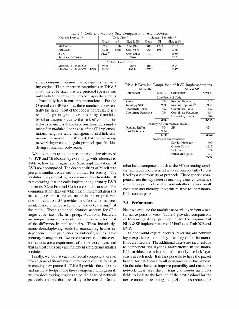
Table 3: Code and Memory Size Comparison of ArchitecturesNetwork Protocol16 Code Size17 Memory Footprint18
Mono SP NLA & SP Mono SP NLA & SPMintRoute 2562 2356 6140(92) 1400 1273 1862PathDCS 6786 4968 6450(988) 1764 1981 1766BVR 642219 - 9060(1512) 1411 - 1889Synopsis Diffusion - - 3686 - - 872
Protocol CoexistenceMintRoute + PathDCS 9348 - 7684 3164 - 1894MintRoute + PathDCS + BVR 16430 - 10354 4575 - 1917
single component in most cases, typically the rout-ing engine. The numbers in parenthesis in Table 3show the code sizes that are protocol-specific andnot likely to be reusable. Protocol-specific code issubstantially less in our implementation21. For theOriginal and SP versions, these numbers are essen-tially the same: most of the code is not reusable as aresult of tight integration, or unusability of modulesby other designers due to the lack of common in-terfaces or unclear division of functionalities imple-mented in modules. In the case of the SP implemen-tations, neighbor-table management, and link esti-mation are moved into SP itself, but the remainingnetwork layer code is again protocol-specific, hin-dering substantial code reuse.
We now return to the increase in code size observedfor BVR and MintRoute, by examining, with reference toTable 4, how the Original and NLA implementations ofBVR are decomposed. The decomposition of MintRoutepresents similar trends and is omitted for brevity. Themodules are grouped by approximate functionality. Itis comforting that the code implementing primary BVRfunctions (Core Protocol Code) are similar in size. Thecommunication stack on which each implementation sitshas a queue and a link estimator in the original ver-sion. In addition, SP provides neighbor-table manage-ment, simple one-hop scheduling, and duty cycling22 ofthe radio. These additional features account for SP’slarger code size. The last group, Additional Features,are unique to our implementation, and account for mostof the difference in total code size. These include dy-namic demultiplexing, tools for maintaining header in-dependence, multiple queues for buffers23, and dynamicmemory management. We note that not all of these ex-tra features are a requirement of the network layer, andthat in most cases one can implement simpler and smallermodules.
Finally, we look at each individual component, drawnfrom a general library which developers can use to assistin creating new protocols. Table 5 provides the code sizeand memory footprint for these components. In general,we consider routing engines to be the heart of networkprotocols, and are thus less likely to be reused. On the
Table 4: Detailed Comparison of BVR ImplementationsMonolithic NLA & SP
Component Size(B) Component Size(B)Core Protocol Code
Router 1194 Routing Engine 1512Topology State 2638 Routing Topology24 2136Coordinate Table 1422 Coordinate Table 1422Coordinate Functions 754 Coordinate Functions 754
Forwarding Engine 5046008 6328
Underlying Communication StackQueuing Buffer 394 SP 4244Link Estimator 2856
3250 4244Additional Functionalities
Service Manager 490Output Queue 1822NetService 324BufferManagerM 252
2888
other hand, components such as the MTree routing topol-ogy are much more general and can consequently be uti-lized by a wider variety of protocols. These generic com-ponents are the key factor in enabling clean co-existenceof multiple protocols with a substantially smaller overallcode size and memory footprint relative to their mono-lithic counterparts.
7.3 Performance
Next we evaluate the modular network layer from a per-formance point of view. Table 6 provides comparisonsof forwarding delay, per module, for the original andNLA & SP implementations of MintRoute, PathDCS andBVR.
As one would expect, packets traversing our networklayer experience more delay than they do in the mono-lithic architecture. The additional delays are incurred dueto component and layering abstractions: in the mono-lithic architecture, it is assumed that only one link layerexists at each node. It is thus possible to have the packetheader format known to all components in the system.On the other hand, to improve portability and reuse, thenetwork layer uses the payload and length meta-datafields to indicate the location of the next payload for thenext component receiving the packet. This reduces the

Table 5: Code Size and Memory Footprint of IndividualComponents
Component Code Size (B) Memory (B)Output Queues
Basic 1822 396Epoch 1892 396Flexible Power Sched. 2696 564
Forwarding EnginesBasic 384 64Opportunistic 1830 169Retransmit 504 64
Routing EnginesBroadcast 42 0MintRoute 92 0PathDCS 988 2BVR 1512 0
Routing TopologiesMTree 2766 88Gradient 372 82
BufferManager 252 84Network Protocol Service 324 24Service Manager 490 8
Table 6: Forwarding Cost ComparisonMono NLA & SP
Protocol Time(µs) Component Time(µs)MintRoute 65 Routing Engine: 19
Routing Topology: 24NetService: 12Output Queue: 573Forwarding Engine: 178
806PathDCS 181 Routing Engine: 165
Routing Topology: 24NetService: 12Output Queue: 573Forwarding Engine: 178
952BVR 3752 Routing Engine: 366
Routing Topology: 2795NetService: 12Output Queue: 573Forwarding Engine: 178
3924
need to know, say, every possible MAC header in exis-tence. The tradeoff is the necessity of additional oper-ations required to access these fields. Furthermore, ad-ditional overhead due to function calls is incurred sincethe network layer is composed of multiple small modulesinstead of just one that is tightly integrated.
We observe a fixed overhead cost induced by NetSer-vice, Output Queue, and Forwarding Engine componentsthat is significant compared to the cost of the simpler pro-tocols. For BVR, which involves more complex lookupprocessing, the relative overhead is considerably smaller,representing a 4.3% increase in forwarding time. Thesenumbers must be placed in perspective: although perfor-mance is important, unlike the Internet, it is not the pri-mary goal. Most applications we see are very low data
rate, low duty-cycle, and the cost in terms of energy ofprocessing a byte is low compared to the cost of send-ing a byte over the radio. On the same platform, it takesat least 6.25ms to forward a common packet of about40 bytes25, and thus even with BVR we are still operat-ing under “line speed”. In none of these examples willpacket processing be a bottleneck. Lastly, the compo-nents can be further optimized to reduce processing time.
8 ConclusionIn this paper we proposed, implemented, and evaluated amodular network layer for sensornets that aims at max-imizing composability and reusability of protocol mod-ules. We verified that many existing protocols fit natu-rally in the architecture, and that less effort is requiredto create new ones. Through evaluation of modules andprotocols implemented in the new network layer, we areable to obtain up to 58% memory reduction and 37% lesscode when running protocols concurrently. Furthermore,we believe that the additional processing latency incurredis acceptable in the context of sensornets.
Looking forward, the work towards a sensornet archi-tecture is still incomplete. One consequence of estab-lishing more strict layering is that certain functionalities,like power management, security, reliability, and timesynchronization, need to be accessible to multiple lay-ers. Our hope is to address these cross-layer issues in thefuture.
Notes1As evidence of that, the original implementations of four routing
algorithms — MintRoute, PathDCS, BVR, and CLDP — have fourdifferent and incompatible implementations of common modules suchas link estimation, neighborhood and queue management.
2 Note that our goal is to facilitate the implementation of network-layer solutions, it does not actually, say, make end-to-end transfer ofdata more reliable. As such, we do not focus on implementing newfunctionalities.
3Minor components, like the dispatcher, are discussed later in § 6.4This can be used by protocol implementing some form of oppor-
tunistic forwarding.5in the case of shared mediums6Network retransmission to alternate next-hops.7Higher layer computes synopsis.8The complete ExOR algorithm is not implemented.9This is just the network layer support for Trickle. The main algo-
rithm runs in the transport layer.10See [12] for details.11Includes variations, like duplicate detection and max TTL.12Requires alternate next-hops.13Requires global cost-to-destination function.14Includes variations like priority, round-robin, fair queuing15Does not guarantee delivery due to local minima.16A dash ’-’ indicates that no implementation existed in that partic-
ular format.17In bytes. This code size includes only network layer code, thus
the code size of SP, approximately 4200 bytes, is not included in thefigures for the SP and NLA & SP implementations.

18In bytes. In order to provide a fair comparison, the memory foot-print figures for SP and NLA & SP implementations include the neigh-bor table overhead portion of the SP memory footprint, as monolithicimplementations maintain their own neighbor table.
19This figure does not include the code for link estimation, as thatfeature is not currently provided in our implementation. With that ca-pability included, the code size is 9278 bytes
20The ‘MintRoute on SP’ combination is the only one in which theoriginal SP implementation [21] is used. All other experiments wererun using an enhanced version [23], which has several additional fea-tures, and thus, larger code size.
21We do not have a figure for Synopsis Diffusion because all of theprotocol-specific functionality for duplicate-insensitive aggregation isat the application level. The network layer components are all reusable.
22Duty-cycling refers to the turning off of the radio from time to timeto conserve energy, which can be consumed even when listening to thechannel.
23Including queues for different message priorities.24The RT in this comparison is not MTree, but an equivalent RT
ported directly from the original BVR code, to make the comparisoncloser.
25The usual size in a sensornet.
References[1] BISWAS, S., AND MORRIS, R. Exor: opportunistic multi-hop
routing for wireless networks. In SIGCOMM ’05: Proceedingsof the 2005 conference on Applications, technologies, architec-tures, and protocols for computer communications (New York,NY, USA, 2005), ACM Press, pp. 133–144.
[2] BOSE, P., MORING, P., STOJMENOVIC, I., AND URRUTIA, J.Routing with guaranteed delivery in ad-hoc wireless networks. InACM Wireless Networks (November 2001).
[3] CONDIE, T., HELLERSTEIN, J. M., MANIATIS, P., RHEA, S.,AND ROSCOE, T. Finally, a use for componentized transportprotocols. In Proceedings of the Fourth Workshop on Hot Topicsin Networks (November 2005).
[4] CULLER, D., DUTTA, P., EE, C. T., FONSECA, R., HUI, J.,LEVIS, P., POLASTRE, J., SHENKER, S., STOICA, I., TOLLE,G., AND ZHAO, J. Towards a sensor network architecture: Low-ering the waistline.
[5] EE, C. T., AND BAJCSY, R. Congestion control and fairnessfor many-to-one routing in sensor networks. In SenSys ’04: Pro-ceedings of the 2nd international conference on Embedded net-worked sensor systems (New York, NY, USA, 2004), ACM Press,pp. 148–161.
[6] EE, C. T., RATNASAMY, S., AND SHENKER, S. Practical data-centric storage. In Proceedings of the Third USENIX/ACM NSDI(San Jose, MA, May 2006).
[7] ESTRIN, D., GOVINDAN, R., HEIDEMANN, J. S., AND KU-MAR, S. Next century challenges: Scalable coordination in sen-sor networks. In Mobile Computing and Networking (1999),pp. 263–270.
[8] FONSECA, R., RATNASAMY, S., ZHAO, J., EE, C.-T.,CULLER, D., SHENKER, S., AND STOICA, I. Beacon-VectorRouting: Scalable Point-to-point Routing in Wireless SensorNetworks. In Proceedings of the Second USENIX/ACM NSDI(Boston, MA, May 2005).
[9] HOHLT, B., DOHERTY, L., AND BREWER, E. Flexible powerscheduling for sensor networks. In IPSN’04: Proceedings of thethird international symposium on Information processing in sen-sor networks (New York, NY, USA, 2004), ACM Press, pp. 205–214.
[10] HUTCHINSON, N. C., AND PETERSON, L. L. The x-kernel: Anarchitecture for implementing network protocols. IEEE Transac-tions on Software Engineering 17, 1 (1991), 64–76.
[11] INTANAGONWIWAT, C., GOVINDAN, R., AND ESTRIN, D. Di-rected diffusion: a scalable and robust communication paradigmfor sensor networks. In Proceedings of the International Confer-ence on Mobile Computing and Networking (Aug. 2000).
[12] KARP, B., AND KUNG, H. T. GPSR: greedy perimeter state-less routing for wireless networks. In International Conferenceon Mobile Computing and Networking (MobiCom 2000) (Boston,MA, USA, 2000), pp. 243–254.
[13] KICZALES, G., LAMPING, J., MENHDHEKAR, A., MAEDA,C., LOPES, C., LOINGTIER, J.-M., AND IRWIN, J. Aspect-oriented programming. In Proceedings European Conference onObject-Oriented Programming, M. Aksit and S. Matsuoka, Eds.,vol. 1241. Springer-Verlag, Berlin, Heidelberg, and New York,1997, pp. 220–242.
[14] KIM, Y., GOVINDAN, R., KARP, B., AND SHENKER, S. Ge-ographic routing made practical. In Proceedings of the SecondUSENIX/ACM Symposium on Networked System Design and Im-plementation (NSDI 2005) (Boston, MA, May 2005).
[15] KOHLER, E., MORRIS, R., CHEN, B., JANNOTTI, J., ANDKAASHOEK, M. F. The Click modular router. ACM Transac-tions on Computer Systems 18, 3 (August 2000), 263–297.
[16] KUHN, F., WATTENHOFER, R., ZHANG, Y., AND ZOLLINGER,A. Geometric ad-hoc routing: Of theory and practice. In Princi-ples of Distributed Computing (2003).
[17] LEVIS, P., AND CULLER, D. Mate: a tiny virtual machine forsensor networks. In Proceedings of the ACM Conference on Ar-chitectural Support for Programming Languages and OperatingSystems (ASPLOS X) (Oct. 2002).
[18] LEVIS, P., PATEL, N., CULLER, D., AND SHENKER, S. Trickle:A self-regulating algorithm for code maintenance and propaga-tion in wireless sensor networks. In First USENIX/ACM Sym-posium on Network Systems Design and Implementation (NSDI)(2004).
[19] LOO, B. T., CONDIE, T., HELLERSTEIN, J. M., MANIATIS, P.,ROSCOE, T., AND STOICA, I. Implementing declarative over-lays. In SOSP ’05: Proceedings of the twentieth ACM symposiumon Operating systems principles (New York, NY, USA, 2005),ACM Press, pp. 75–90.
[20] NATH, S., GIBBONS, P. B., SESHAN, S., AND ANDERSON,Z. R. Synopsis diffusion for robust aggregation in sensor net-works. In Proceedings of the 2nd ACM Conference on EmbeddedNetworked Sensor Systems (Sensys) (New York, NY, USA, 2004),ACM Press, pp. 250–262.
[21] POLASTRE, J., HUI, J., LEVIS, P., ZHAO, J., CULLER, D.,SHENKER, S., AND STOICA, I. A unifying link abstraction forwireless sensor networks. In Proceedings of the Third ACM Con-ference on Embedded Networked Sensory Systems (SenSys) (Nov.2005).
[22] RODRIGUEZ, A., KILLIAN, C., BHAT, S., KOSTIC, D., ANDVAHDAT, A. Macedon: Methodology for automatically creating,evaluating, and designing overlay networks. In Proceedings of thefirst USENIX/ACM Symposium on Networked System Design andImplementation (NSDI 2004) (San Francisco, CA, March 2004),pp. 267–280.
[23] TAVAKOLI, A., TANEJA, J., DUTTA, P., CULLER, D.,SHENKER, S., AND STOICA, I. Evaluation and Enhancement ofa Unifying Link Abstraction for Sensornets. Under submission.
[24] WOO, A., TONG, T., AND CULLER, D. Taming the underlyingchallenges of reliable multihop routing in sensor networks. InProceedings of the first international conference on Embeddednetworked sensor systems (2003), ACM Press, pp. 14–27.
[25] Crossbow. http://www.crossbow.com.