Embed Size (px)
Citation preview

A MOMENTUM TRANSFER MEASUREMENT EXPERIMENT BETWEEN CONTACTING BODIES IN THE PRESENCE OF ADHESION UNDER NEAR-
ZERO GRAVITY CONDITIONS
M. Benedetti1, D. Bortoluzzi2, M. De Cecco2 and L. Baglivo3
1Department of Materials Engineering and Industrial Technologies, University of Trento, 38050 Trento, Italy
2Department of Mechanical and Structural Engineering, University of Trento, 38050 Trento, Italy 3Department of Mechanical Engineering, University of Padova, 35131 Padova, Italy
ABSTRACT
The present paper is aimed at investigating the dynamics of release of objects in free-falling conditions typical of space applications. In the presence of surface interaction forces, a quick separation of the released from the constraining body will result in a momentum transfer, provided that the inertial forces exceed the maximum attractive force. The release conditions as well as the related parameters affecting the momentum acquired by the released body through the adhesion rupture play a fundamental role. An experimental technique aimed at measuring the momentum transfer has been developed. Particular attention has been placed on the capability to accurately reproduce the stress status on the contact patch, on the noise sources affecting the measurement, and on the performances of a noise optimal-filtering technique.
Introduction
The measurement of small impulses is necessary in various fields of science and engineering. For instance, in space propulsion studies, the exact knowledge of the impulse imparted by the thrusters to an orbiting satellite is needed for orbit maintenance, repositioning and attitude control. In the applications mentioned, the measured impulse is originated by a non-contact force that may be electro-magnetic, or inertial (accelerated ions or gas molecules). The advantage thereof resides in the fact that this kind of forces, although acting between two bodies, is not affected by means such bodies are constrained. Conversely, the present work deals with an application where the measurement of impulse concerns contacting bodies. In space environment, the in-orbit precise release of bodies implies the contact with some kind of caging devices, that involves the sudden rupture of adhesive forces with consequent transfer of momentum. The breaking of adhesive junctions between contacting bodies, although of slight order of magnitude (from nano- up to milliNewtons), can be promoted in space applications neither by environmental factors, like the gravity field, nor surface contaminants caused by exposure to the atmosphere, nor acoustic noise propagated by the air, nor inertia forces due to ground micro-seismic movement. The unavoidable momentum transferred to the released body may result in too high residual velocities as compared to the required release conditions. A meaningful example of these issues is given by the scientific space mission LISA (Laser Interferometer Space Antenna) [1]. Aim of this ESA NASA joint mission is the first in-flight revealing of gravitational waves, which will be detected by means of laser interferometers arms formed among three orbiting satellites. The gravitational waves sensing elements, constituting the end-mirrors of the interferometer arms, will be 2 kg cubic masses located within the satellites. During the experiment, the test masses will be set in free flight. In contrast, during launch, the test masses need to be firmly secured to their housings in order to avoid shaking and thus damage. The release of the test masses for the experiment constitutes a mission potential single-point failure, because it must rely on a limited force and torque authority supplied by a capacitive actuation system and on a limited acceleration of the caging device. The residual velocity of the test mass must be less than 5 µm/s, this means 10-5 kg·m/s TM linear momentum, otherwise the capacitive actuation will not be able to catch up the test mass. It is now clear that the exact measurement of the momentum imparted to the test mass due to adhesive interactions plays a crucial role for a successful release. This paper presents a ground-based experimental campaign aimed at investigating the influence of adhesion forces on the momentum transfer between objects in representative conditions of the space environment, representing the LISA TM and release-dedicated plunger. This is not an easy task because of several environmental sources of disturbance that have to be biased off. In fact, a basic requirement of the ground-based experiment is to prevent adhesion rupture induced by force/torque components acting along constrained degrees of freedom of the experimental device. Moreover, the LISA TM release poses a

demanding requirement on the measurement resolution of the experiment; in fact, this shall be 2 or 3 orders of magnitude lesser than the maximum allowed linear momentum, i.e. fractions of µN·s. The main objectives of this article are to (a) describe the measurement principle and the experimental setup, (b) characterize the experiment performances in terms of measurement resolution, (c) illustrate the preliminary experimental results obtained.
Measurement Technique
Precise measurement of impulse performed by other authors [2, 3] resulted critical, mainly for two reasons. Firstly, the force impulse needs to be entirely converted into momentum; therefore, any other force acting in the same direction on the body subjected to the impulse must be minimized. Secondly, the momentum must be identified by the measurement of the resulting motion of the body that is affected by noise sources and by the unavoidable constraining forces. The conversion of impulse into momentum may be guaranteed by a suspension system that minimizes the risk of any impulsive constraining force in the direction of the impulse to be measured. Suspension systems based on simple pendulum, linear rail and torsion pendulum [3] have been adopted to provide a weakly constrained axis. The presence of a single weakly constrained degree of freedom does not limit the measurement, as long as the impulsive force is a non-contact force and it is reasonably aligned with the “soft” axis. On the contrary, the impulsive force due to adhesion rupture is affected by the complete three-axial stress status at the contact patch that depends on how both contacting bodies are constrained to ground. This means that the body subjected to the adhesive impulse needs to be weakly constrained not only in the direction along which the plunger is retracted, but also along the orthogonal directions. Neglecting, for the moment, the stiff constraint along the vertical direction, many different solutions provide a suitable inertial isolation along two axes [4]. Accordingly, the simple pendulum model for the inertial isolation system has been chosen to investigate the possible performance of the transferred momentum measurement experiment. As long as the pendulum length is compatible with the typical height of a laboratory ceiling (i.e. meter scale), the preferred practical implementation is the simple pendulum characterized by easily determinable dynamic properties (quality factor and resonant frequency) and still providing good isolation from gravity and micro-seismic noise. The basic concept of the measuring apparatus, illustrated in Fig. 1, is to suspend both the test mass and the release plunger from two pendulums. A position sensor detects the weakly damped oscillation of the test mass due to the momentum transferred upon pulling the plunger away.
Figure 1. The concept of the momentum transfer measurement setup: two pendulums with nominally equal lengths
representing the TM and the plunger respectively. A position sensor detects the motion of the TM due to the momentum transferred upon pulling the plunger away.
In such a configuration, however, the stress status on the contact patch may be in principle far different in the ground experiment from the in-flight conditions. The in-flight release takes place with an unconstrained test mass, and for equilibrium shear stresses at the contact patch are allowed neither along the t-axis nor along the s-axis. In the ground experiment (see Fig. 2), both the test mass mock-up and the plunger mock-up need to be suspended with some constraining stiffness to ground, named Kn, Kt and Ks. There are two main reasons for keeping the constraining stiffness to the lowest possible value: • Gravity-aided detachment. The separation of the contacting bodies involves the fracture of the bonding junction. Since all
stress components acting on the junction contribute to its fracture, the presence of shear stress in the ground-based experiment may help the rupture of adhesion and leads to an underestimation of the impulse occurred at the separation with respect to the in-flight conditions. The risk of a gravity-aided adhesion rupture may be firstly limited by adopting a very light plunger mock-up that is represented by a millimetre-order diameter sphere. Secondly, the tension on the plunger
mock-up suspending wire is measured by a load cell in order to monitor any variation of the vertical force with respect to the weight during the approach to the test mass mock-up.
• Micro-seismic related kinetic energy. The adhered plunger constitutes a body bound in a force potential well. One condition in order the momentum transfer not to be obscured by other phenomena related to the ground environment is that the force noise acting on the TM and the plunger (e.g., seismic noise) does not induce on the plunger a kinetic energy relative to the TM sufficient to overcome the binding energy. Consequently, the suspension system shall provide sufficient isolation from noise sources acting in the laboratory environment.
Figure 2. Schematic representation of the ground-based experiment of the release of two initially contacting bodies. The K
coefficients are the constraining stiffness components. The suffixes 1 and 2 refer to the suspending points of the two objects.
Different techniques have been used in the literature to extract the applied impulse from the measured free oscillation of the suspended system [3]. In this paper, we adopted the standard Wiener-Kolmogorov Filter (WKF) theory of optimal estimation ([5]) to assess the momentum transferred by an impulsive force to a harmonic oscillator. We assume that a harmonic oscillator of mass m, resonant angular frequency w and quality factor Q, is subject to a force of total impulse P0. The measure of the position x of the oscillator is affected by a stationary and Gaussian noise with PSD Sx(ω). The momentum transferred from the force to the mass is measured from the motion of the oscillator as detected by the position transducer, which is given by: ( ) ( ) ( )x t As t n t= + (1) where s(t) is the response signal of the system to a unit impulse (known), A is the signal amplitude, function of the unknown impulse, and n(t) is the noise. We now look for an optimal estimator of the signal amplitude from a linear combination of the data x(t):
0
ˆ( ) ( ') ( ')d '
T
A T h t x T t t= !" (2)
where the ‘filter’’ function h(t) has to be chosen such that is an unbiased estimator and its variance is minimal. It can be demonstrated that the standard deviation of the transferred momentum estimation is given by:
0
1
2
2 2 2 2 2 2
0 0
2
1
( ) /1d
2 ( )P
x
Q
m S
! ! ! !" !
# !
$
%
$%
& '( )$ +( )=
( )( )* +
, (3)
Notably, the measurement accuracy of the transferred momentum increases with decreasing TM mass, suggesting the employment of a light mock-up of the TM itself in the release experiment.
Measurement Apparatus
The transferred momentum measurement facility (TMMF), shown in Fig. 3, consists in a vacuum chamber in which the two mock-ups are suspended by means of 1-m long pendulums, and in an optical bench where the optical measurement of the test-mass mock-up displacement, pitch and yaw is implemented. The facility can be schematically subdivided in 4 subsystems: • Vacuum system. It is devoted to guarantee the high vacuum level needed for the experiment • Suspension and positioning stage. It is aimed at suspending TM and plunger mock-ups as well as at positioning the TM

with respect to the plunger mock-up (along x, y, z and f-axes, where f-rotation is around z-axis). In addition, this subsystem is devoted to monitor the force acting along the suspension fibre of the release plunger by means of a load cell.
• Measurement system. This subsystem is devoted to measure the position and attitude of the TM mockup. The TM position along the x-direction is monitored by a laser interferometer in homodyne configuration, rigidly mounted on an optical window fixed to the vacuum chamber, and detecting the TM through an optical viewport. The TM attitude (pitch and yaw) is monitored by an optical leverage, realized with a laser beam reflected by the TM rear (-x) surface and hitting a Position Sensing Device.
• Actuation system. This subsystem is devoted to the actuation of the release plunger along the direction monitored by the laser interferometer (x-axis). Moreover, the position of the actuation point can be varied by means of a positioning stage (along z-axis).
Figure 3. Overall layout of the transferred momentum measurement facility. The experiment fulfils the basic requirements to guarantee the smallest risk of shear-aided detachment between the two bodies, by means of a very light plunger and the monitoring of the vertical constraining force exerted by its suspending fibre. This set-up also minimizes the effect of ground micro-seismic motion on the suspended system that may help adhesion rupture. Although any adhesive phenomenon arising from the preloading force between TM and finger may be progressively reduced by iteration of the detachment and lighter re-attachment of the mating surfaces, there is an adhesion threshold due to conservative interactions (Van Der Waals, electrostatic) under which the developed impulse upon rupture can not be reduced. Aim of the designed setup is then to characterize the adhesive impulse in the case of a virtually zero-preload, in order to set a lower limit of the possible momentum transfer. Thus, the TM needs also to be lightened in its mock-up version in order to reduce the restoring force per unit displacement. This reduces the risk of undesired pre-load between the two bodies and lets the TM develop a more detectable oscillation after the impulse action.
Measurement Accuracy
The preliminary setup of the TMMF is intended to characterize the measurement performance in terms of accuracy on the imparted linear momentum to the TM. Therefore, simplified mock-ups have been used. Their machining was pretty rough, with relaxed dimensional tolerances, and no particular attention has been paid to the cleanliness level of the contacting surfaces. In addition, the performance of the plunger actuation stage in terms of maximum acceleration is significantly lower than that foreseen for the flight model. Fig. 4 shows in detail the mock-ups of the Test Mass and the plunger. The TM is a prismatic 18×18×5 mm3 Al specimen suspended from a 1.14 m long Al wire with 0.125 mm diameter. The contacting surface has been mechanically polished. The plunger is a 2mm diameter Al-sphere suspended on a 1.14 m long W wire with 0.02 mm diameter and retracted by a 30 mm long W wire with 0.02 mm diameter. The plunger retraction fibre is actuated by a linear stage along the x-direction.

Figure 4. TM and plunger mock-ups used in the preliminary setup. The position measurement noise as well as the micro seismic horizontal displacement and tilt constitute the major sources of physical disturbance superimposed on the TM free oscillations. Therefore, a noise model has been elaborated to evaluate the accuracy of the transferred momentum measurement. As a first cut to the problem, the noise model has been kept as simple as possible, in order to have a total noise at the measurement signal whose power spectral density (PSD) may be described by functions that still allow for analytical manipulation in the optimal filtering technique. Typical measured horizontal and tilt noise PSDs have been reviewed, and, considering that most of their effect is concentrated in a narrow range around resonance, the following noise model has been considered suitable (see Table 1): (a) both horizontal and tilt noise have been considered zero-mean stationary and Gaussian stochastic processes; (b) the horizontal displacement noise PSD SXs(ω) is assumed constant in acceleration, whereas the tilt noise PSD SΘs(ω) is assumed constant in velocity; (c) the two noise sources have been considered uncorrelated. The model of the noise present in the TM x-displacement measurement signal is completed by adding a zero-mean stationary Gaussian white noise of the sensor Sn(ω). By means of the transfer functions from seismic noise to TM displacement, the PSD of the total noise can be calculated ( ) ( ) ( ) ( ) ( ) ( )!!!!!!
nssXsXsxSSHSHS ++=
""
22 (4)
where HXs(ω) is the transfer function from seismic acceleration noise and HΘs(ω) from seismic tilt velocity noise to TM displacement.
Parameter Symbol Value Unit Horizontal acceleration
seismic noise PSD SXs(ω) 4 10-13 m2s-4/Hz
Tilt angular velocity seismic noise PSD SΘs(ω) 2.5·10-17 rad2s-2/Hz
Position sensor noise PSD Sn(ω) 10-18 m2/Hz Table 1. Values of noise parameters used in the calculations.
Figure 5. Spectral density of the measurement noise of the laser interferometer used to monitor the TM position.
The laser interferometer noise has been evaluated by measuring the position with respect to the measuring device of a mirror rigidly mounted inside the vacuum chamber. The spectral density of the position measurement noise, plotted in Fig. 5, has been obtained by signal detrending, averaging 10 time windows, and by Hemming windowing. It can be noted that the spectral
density is equal to about 10-9 m/√Hz around the 0.465Hz resonant frequency of the pendulum, where most of its effect is concentrated. The measurement noise PSD has then been assumed constant and equal to 10-18 m2/Hz. Furthermore, the laser interferometer has been used to measure the free oscillation of the TM mock-up over a long time scale (10 h). In Figure 6, the spectral density of the position measurement, obtained by averaging 10 time windows and by applying the Hemming windowing, is compared with that predicted by Eq. (4) using the PSD values indicated in Table 1. Noteworthy, the adopted noise model accurately reproduces the experimental data (see Fig. 6); in addition, the PSDs of horizontal and tilt seismic noise reported in Table 1 are in very good agreement with the literature (e.g., see [6]). By substituting in Eq. (3) the oscillator parameters and the total noise spectral density, the standard deviation σPo results 2·10-9 kg·m/s, therefore 4 orders of magnitude lower than the maximum allowed LISA TM momentum. Finally, it should be pointed out that there are additional influence factors on the resulting accuracy, e.g. misalignements, transuder noises, etc. In a future work, these influence factors will be analyzed in order to estimate the overall accuracy
Figure 6. Spectral density of the TM position noise deduced from the free oscillations of the TM inside the vacuum chamber.
The red line corresponds to the TM noise model expressed by Eq. (4).
Experimental Procedures
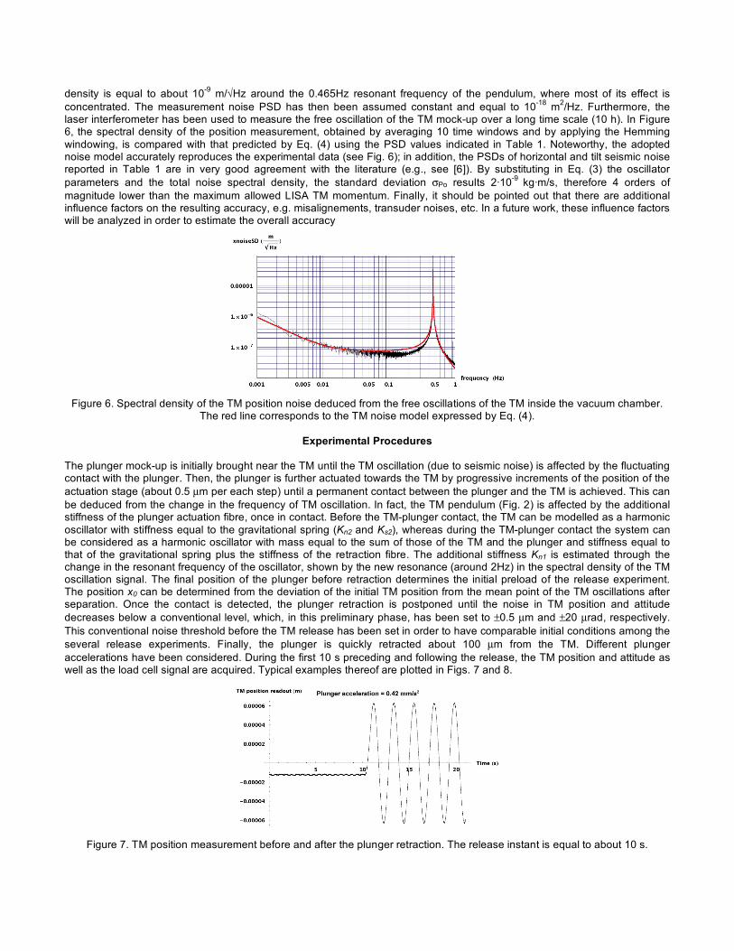
The plunger mock-up is initially brought near the TM until the TM oscillation (due to seismic noise) is affected by the fluctuating contact with the plunger. Then, the plunger is further actuated towards the TM by progressive increments of the position of the actuation stage (about 0.5 µm per each step) until a permanent contact between the plunger and the TM is achieved. This can be deduced from the change in the frequency of TM oscillation. In fact, the TM pendulum (Fig. 2) is affected by the additional stiffness of the plunger actuation fibre, once in contact. Before the TM-plunger contact, the TM can be modelled as a harmonic oscillator with stiffness equal to the gravitational spring (Kn2 and Ks2), whereas during the TM-plunger contact the system can be considered as a harmonic oscillator with mass equal to the sum of those of the TM and the plunger and stiffness equal to that of the gravitational spring plus the stiffness of the retraction fibre. The additional stiffness Kn1 is estimated through the change in the resonant frequency of the oscillator, shown by the new resonance (around 2Hz) in the spectral density of the TM oscillation signal. The final position of the plunger before retraction determines the initial preload of the release experiment. The position x0 can be determined from the deviation of the initial TM position from the mean point of the TM oscillations after separation. Once the contact is detected, the plunger retraction is postponed until the noise in TM position and attitude decreases below a conventional level, which, in this preliminary phase, has been set to ±0.5 µm and ±20 µrad, respectively. This conventional noise threshold before the TM release has been set in order to have comparable initial conditions among the several release experiments. Finally, the plunger is quickly retracted about 100 µm from the TM. Different plunger accelerations have been considered. During the first 10 s preceding and following the release, the TM position and attitude as well as the load cell signal are acquired. Typical examples thereof are plotted in Figs. 7 and 8.
Figure 7. TM position measurement before and after the plunger retraction. The release instant is equal to about 10 s.

Figure 8. Load signal acquired by the load cell acting on the plunger suspension fibre. The plunger weight is detracted from
the load signal.
Figure 9. Variation of the estimated linear momentum with the postulated release instant.
The application of the filter function to the acquired data, detracted of the contribution of the initial position x0, gives the estimation of the imparted impulse. Finally, no appreciable load was measured along the plunger suspension fibre during the retraction. However, the exact release instant t0 is unknown. This must be inferred from the hypothesis that t0 corresponds to the instant in which the momentum transfer is maximum. In order to do this, the filtering function is applied to the signal by setting the reference instant (in which the impulse is assumed to be applied) in different sampled points around the nominal t0. Figure 9 displays the dependence of the estimated impulse on the release instant t0. It can be noted that the maximum value of the estimated TM linear momentum is achieved some tenths of second after the nominal release instant, due to motor drivers delay. This value will be considered in the following as the linear momentum transferred to the TM owing to the adhesion forces acting during the plunger retraction.
Results
Figure 10 summarizes the results of the preliminary tests carried out at several TM initial positions, that determine the contact preload, and plunger acceleration. It can be noted that, in the explored range, the preload seems not to exert a significant effect on the momentum transfer. In fact, the explored values of the plunger preload lie in the conservative adhesion regime of the material [7]. Therefore, only reversible interactions are expected to act between plunger and TM. Under these circumstances, the preload does not affect the imparted linear momentum. On the contrary, this increases in mean value with decreasing plunger acceleration values according to the model illustrated in [8] and expressed by:
0
2
Up
r a
!= (5)
where p is the impulse imparted to the TM, ΔU is the adhesion potential energy difference between TM and plunger, r0 is the separation distance where the interaction force can be considered negligible and a is the plunger acceleration. The term ΔU/√r0 can be assumed constant in the performed release experiments. Therefore, a data fit has been carried out using the collected data in order to derive the value of this constant term, obtaining a value of about 8·10-9 J/√m. Putting into Eq. (4) r0 = 1 µm [9], a value of the adhesion potential energy difference equal to 8·10-12 J is obtained, in good agreement with [10].

Figure 10. Estimated linear momentum transferred to the TM for different plunger accelerations and preloads.
This makes it possible to estimate the effect of the seismic motion on the detachment of the two bodies. If the kinetic energy, which the plunger would assume with respect to the TM under the forcing action of the seismic motion transmitted by both the suspending and the pulling fibers, is comparable with the binding energy, this would assist the adhesion rupture. The relative velocity of the plunger with respect to the TM is estimated by means of the transfer functions from the seismic horizontal acceleration to the relative velocity. The kinetic energy due to seismic noise, calculated from Eq. (6), results 4·10-15 J, i.e. 3 orders of magnitude lower than the estimated binding energy. Therefore, the kinetic contribution to the release is negligible.
2
-
1 1( )d
2 2k pl pl VE m v m S f f
!
!
= = " (6)
Conclusions
The present paper focused on the measurement of the momentum transfer occurred when two free-falling bodies interacting with surface forces are impulsively separated, in order to investigate the dynamics of release in the absence of gravity. A measuring technique based on two pendulums, suspending the separating bodies, has been analyzed in terms of the capability to accurately reproduce the stress status on the contact patch. Particular attention has been paid to the noise sources affecting the measurement and on the achievable measurement accuracy of a noise optimal-filtering technique. The developed experiment enables the ground-based verification of mechanisms devoted to the precise in-orbit release of objects. The measured transferred momentum, though with non-representative mock-ups, shows a good margin with respect to the imposed LISA requirement. References 1. Benedetti, M., Bortoluzzi, D., Da Lio, M., and Fontanari, V., “The Influence of Adhesion and Sub-Newton Pull-Off Forces
on the Release of Objects in Outer Space”, ASME J. Tribology, 128, 828-840 (2006). 2. Selden, N. P., Ketsdever, A. D., “Comparison of force balance calibration techniques for the nano-Newton range”, Rev.
Sci. Instr., 74, 5249-5254 (2003). 3. D’Souza, B. C., Ketsdever, A. D., “Investigation of time-dependent forces on a nano-Newton-second impulse balance”,
Rev. Sci. Instr., 76, 015105 1-10 (2005). 4. Biral, F., Bortoluzzi, D., and Da Lio, M., “Dynamical optimization of a Roberts linkage-based inertial sensor for ground
testing of a scientific space mission critical phase”, In Multibody Dynamics 2005, Madrid, Spain, 21-24 June 2005. 5. Papoulis, A., Probability, random variables, and stochastic processes, McGraw-Hill (1984). 6. McNamara, D. E., and Buland, R. P., “Ambient Noise Levels in the Continental United States,” Bulletin of the
Seismological Society of America, 94, 1517-1527 (2004). 7. Gane, N., Pfaelzer, P.F., and Tabor, D., “Adhesion between Clean Surfaces at Light Loads”, Proceedings of the Royal
Society of London A, 340, 495-517 (1974). 8. Benedetti, M., Bortoluzzi, D., and Vitale, S., “A Momentum Transfer Measurement Technique between Contacting Free
Falling Bodies in the Presence of Adhesion”, ASME Journal of Applied Mechanics (submitted). 9. Biggs S., Mulvaney P., “Measurement of the Forces between Gold Surfaces in Water by Atomic Force Microscopy”, J.
Chem. Phys., 100, 8501–8505 (1994). 10. Tadmor, R. The London-van der Waals Interaction Energy between Objects of Various Geometries. J. Physics
Condensed Matter., 13, L195-L202 (2001).