Embed Size (px)
Citation preview
A Multi-Agent System for the automated handlingof experimental protocols in biological laboratories
Alessandro Maccagnan∗, Tullio Vardanega∗, Erika Feltrin†, Giorgio Valle†, Mauro Riva‡, Nicola Cannata§∗Department of Pure and Applied Mathematics, University of Padua, via Trieste 63, 35121 Padova, Italy
†CRIBI Biotechnology Centre, University of Padua, viale G. Colombo 3, 35121 Padova, Italy‡BMR Genomics, Via Redipuglia 21/a, 35131 Padova, Italy
§School of Sciences and Technologies, University of Camerino, Via Madonna delle Carceri 9, 62032 Camerino, Italy
Abstract—Software-based Laboratory Information Manage-ment Systems can handle samples, plates, instruments, users,potentially up to the automation of whole workflows. Onefrustrating element of this predicament is that Life Scienceslaboratory protocols are normally expressed in natural languagesand thus are scarcely amenable to real automation. We want todefeat this major limitation by way of a project combining Model-Driven Engineering, Workflows, Ontologies and Multiagent sys-tems (MAS). This paper describes the latter ingredient. Our MAShas been implemented with JADE and WADE to automaticallyinterpret and execute a structured representation of laboratoryprotocols expressed in XPDL+OWL. Our work has recently beentested on a real test case and will shortly be deployed in the field.
I. INTRODUCTION
Following the explosion of automation technologies in lifescience experimentation, biological laboratories are drown-ing in data to handle, store, and analyze. High-throughput”-omics” experiments permit to rapidly characterize wholepopulations of molecules (e.g. genes, transcripts, proteins,metabolites) in different samples at varying physiologi-cal/pathological/environmental conditions. Automatic process-ing of samples has therefore become essential in modernlife sciences. For decades, Information Technology supportslaboratories by means of LIMS (Laboratory Information Man-agement Systems), software for the management of sam-ples, plates, laboratory users and instruments and for theautomation of work flow. Furthermore, formal representationof experimental knowledge is increasingly used, so that ”robot-scientists” [1] could even automatically infer new knowledgeand plan subsequent experimental steps in order to confirmexperimental hypotheses [2].
In natural sciences a protocol is a predefined proceduralmethod, defined as a sequence of activities, used to designlaboratory experiments and operations. In general they arestill commonly described, published and exchanged in nat-ural language and come therefore accompanied by intrinsicambiguity, lack of structure and ”disconnection” from thesurrounding execution environment. This make experimentshardly repeatable, not machine-understandable, even not easilycomprehensible by a laboratory expert and most definitivelynot directly automatable and unfit for automated reasoning. Wehave therefore undertaken we have proposed to combine the
unambiguous semantic of ontologies with the expressive powerof workflows for formalizing protocols adopted in biologicallaboratories [3]. By means of workflows, protocols can beintuitively and visually represented and can be stored andshared using the XPDL standard interchange language [4]. Bymeans of ontologies the knowledge related to the laboratoryenvironment is directly incorporated into the workflow modeland can be exchanged using the standard OWL model [5].
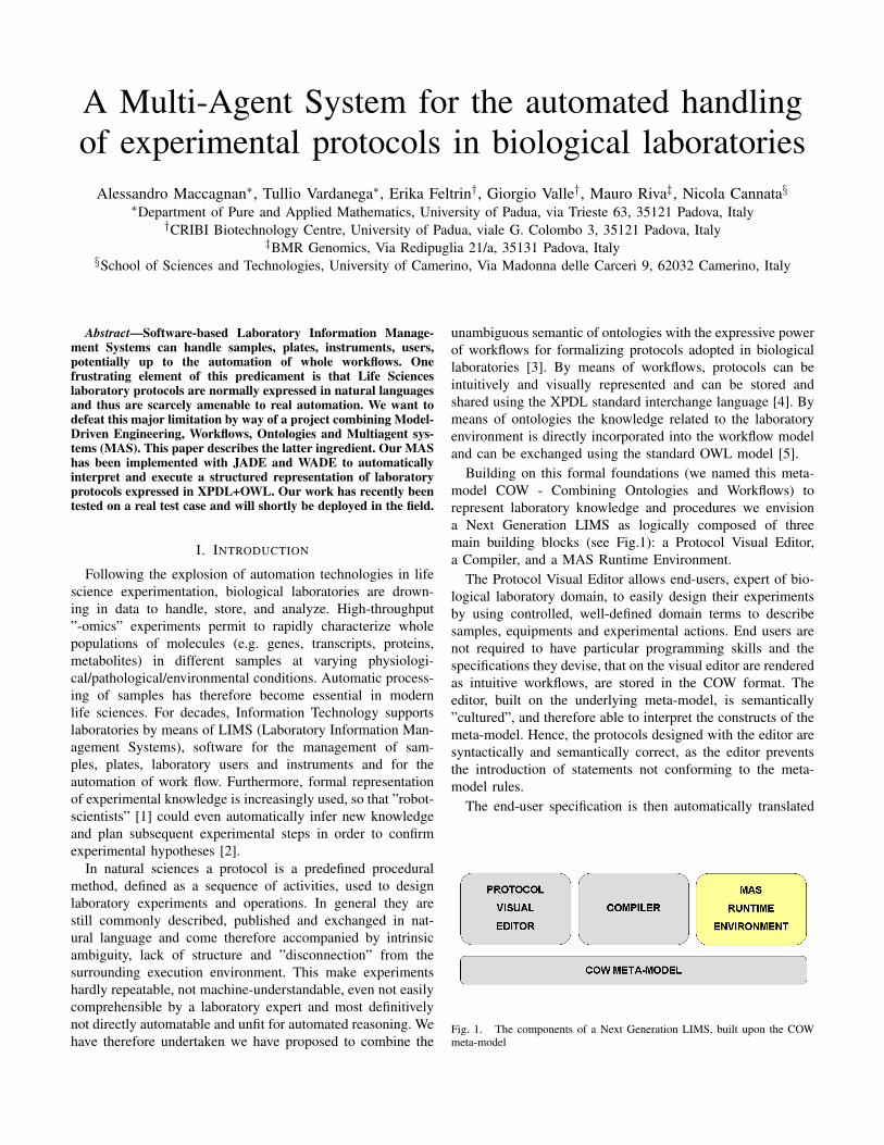
Building on this formal foundations (we named this meta-model COW - Combining Ontologies and Workflows) torepresent laboratory knowledge and procedures we envisiona Next Generation LIMS as logically composed of threemain building blocks (see Fig.1): a Protocol Visual Editor,a Compiler, and a MAS Runtime Environment.
The Protocol Visual Editor allows end-users, expert of bio-logical laboratory domain, to easily design their experimentsby using controlled, well-defined domain terms to describesamples, equipments and experimental actions. End users arenot required to have particular programming skills and thespecifications they devise, that on the visual editor are renderedas intuitive workflows, are stored in the COW format. Theeditor, built on the underlying meta-model, is semantically”cultured”, and therefore able to interpret the constructs of themeta-model. Hence, the protocols designed with the editor aresyntactically and semantically correct, as the editor preventsthe introduction of statements not conforming to the meta-model rules.
The end-user specification is then automatically translated
Fig. 1. The components of a Next Generation LIMS, built upon the COWmeta-model
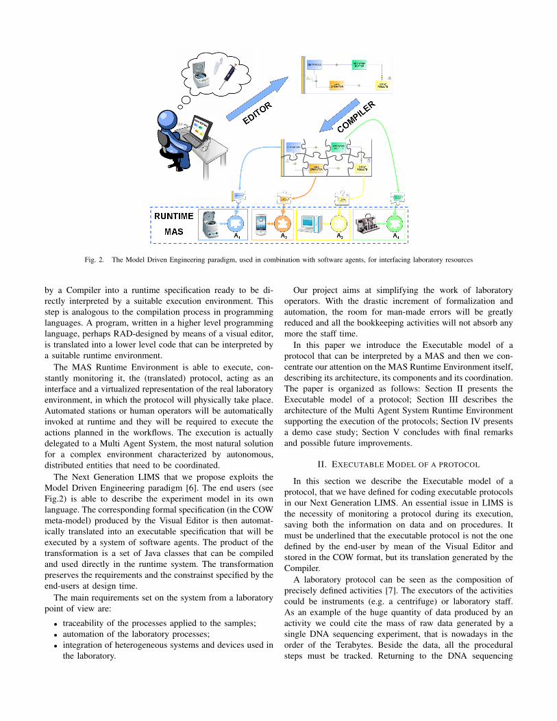
Fig. 2. The Model Driven Engineering paradigm, used in combination with software agents, for interfacing laboratory resources
by a Compiler into a runtime specification ready to be di-rectly interpreted by a suitable execution environment. Thisstep is analogous to the compilation process in programminglanguages. A program, written in a higher level programminglanguage, perhaps RAD-designed by means of a visual editor,is translated into a lower level code that can be interpreted bya suitable runtime environment.
The MAS Runtime Environment is able to execute, con-stantly monitoring it, the (translated) protocol, acting as aninterface and a virtualized representation of the real laboratoryenvironment, in which the protocol will physically take place.Automated stations or human operators will be automaticallyinvoked at runtime and they will be required to execute theactions planned in the workflows. The execution is actuallydelegated to a Multi Agent System, the most natural solutionfor a complex environment characterized by autonomous,distributed entities that need to be coordinated.
The Next Generation LIMS that we propose exploits theModel Driven Engineering paradigm [6]. The end users (seeFig.2) is able to describe the experiment model in its ownlanguage. The corresponding formal specification (in the COWmeta-model) produced by the Visual Editor is then automat-ically translated into an executable specification that will beexecuted by a system of software agents. The product of thetransformation is a set of Java classes that can be compiledand used directly in the runtime system. The transformationpreserves the requirements and the constrainst specified by theend-users at design time.
The main requirements set on the system from a laboratorypoint of view are:
• traceability of the processes applied to the samples;• automation of the laboratory processes;• integration of heterogeneous systems and devices used in
the laboratory.
Our project aims at simplifying the work of laboratoryoperators. With the drastic increment of formalization andautomation, the room for man-made errors will be greatlyreduced and all the bookkeeping activities will not absorb anymore the staff time.
In this paper we introduce the Executable model of aprotocol that can be interpreted by a MAS and then we con-centrate our attention on the MAS Runtime Environment itself,describing its architecture, its components and its coordination.The paper is organized as follows: Section II presents theExecutable model of a protocol; Section III describes thearchitecture of the Multi Agent System Runtime Environmentsupporting the execution of the protocols; Section IV presentsa demo case study; Section V concludes with final remarksand possible future improvements.
II. EXECUTABLE MODEL OF A PROTOCOL
In this section we describe the Executable model of aprotocol, that we have defined for coding executable protocolsin our Next Generation LIMS. An essential issue in LIMS isthe necessity of monitoring a protocol during its execution,saving both the information on data and on procedures. Itmust be underlined that the executable protocol is not the onedefined by the end-user by mean of the Visual Editor andstored in the COW format, but its translation generated by theCompiler.
A laboratory protocol can be seen as the composition ofprecisely defined activities [7]. The executors of the activitiescould be instruments (e.g. a centrifuge) or laboratory staff.As an example of the huge quantity of data produced by anactivity we could cite the mass of raw data generated by asingle DNA sequencing experiment, that is nowadays in theorder of the Terabytes. Beside the data, all the proceduralsteps must be tracked. Returning to the DNA sequencing
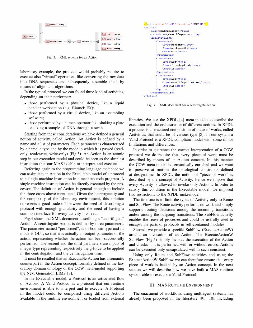
Fig. 3. XML schema for an Action
laboratory example, the protocol would probably require toexecute also ”virtual” operations like converting the raw datainto DNA sequences and subsequently assemble them bymeans of alignment algorithms.
In the typical protocol we can found three kind of activities,depending on their performer:
• those performed by a physical device, like a liquidhandler workstation (e.g. Biomek FX);
• those performed by a virtual device, like an assemblingsoftware;
• those performed by a human operator, like shaking a plateor taking a sample of DNA through a swab.
Starting from these considerations we have defined a generalnotion of activity, called Action. An Action is defined by aname and a list of parameters. Each parameter is characterizedby a name, a type and by the mode in which it is passed (read-only, read/write, write-only) (Fig.3). An Action is an atomicstep in our execution model and could be seen as the simplestinstruction that our MAS is able to interpret and execute
Referring again to the programming language metaphor wecan assimilate an Action in the Executable model of a protocolto a single machine instruction in a machine code program. Asingle machine instruction can be directly executed by the pro-cessor. The definition of Action is general enough to includethe three cases above mentioned. Given the heterogeneity andthe complexity of the laboratory environment, this solutionrepresents a good trade-off between the need of describing aprotocol with enough granularity and the need of having acommon interface for every activity involved.
Fig.4 shows the XML document describing a ”centrifugate”Action. A centrifugate Action is defined by three parameters.The parameter named ”performed”, is of boolean type and itsmode is OUT, so that it is actually an output parameter of theaction, representing whether the action has been successfullyperformed. The second and the third parameters are inputs ofinteger type representing respectively the g-force to be appliedin the centrifugation and the centrifugation time.
It must be recalled that an Executable Action has a semanticcounterpart in the Action concept, formally defined in the lab-oratory domain ontology of the COW meta-model supportingthe Next Generation LIMS [3].
In the Executable model, a Protocol is an articulated flowof Actions. A Valid Protocol is a protocol that our runtimeenvironment is able to interpret and to execute. A Protocolin the model could be composed using different Actionsavailable in the runtime environment or loaded from external
Fig. 4. XML document for a centrifugate action
libraries. We use the XPDL [4] meta-model to describe theexecution and the orchestration of different actions. In XPDLa process is a structured composition of piece of works, calledActivities, that could be of various type [8]. In our system aValid Protocol is a XPDL compliant model with some minorlimitations and differences.
In order to guarantee the correct interpretation of a COWprotocol we do require that every piece of work must bedescribed by means of an Action concept. In this mannerthe COW meta-model is semantically enriched and we wantto preserve at runtime the ontological constraints definedat design-time. In XPDL the notion of ”piece of work” isdescribed by the concept of Activity. Hence we impose thatevery Activity is allowed to invoke only Actions. In order tosatisfy this condition in the Executable model, we imposedtwo restrictions to the XPDL meta-model.
The first one is to limit the types of Activity only to Routeand SubFlow. The Route activity performs no work and simplysupports routing decisions among the incoming transitionsand/or among the outgoing transitions. The SubFlow activityenables the reuse of processes and could be usefully used toencapsulate parts of protocols in self-contained modules.
Second, we provide a specific SubFlow (ExecuteActionW)around an invocation of an Action. The ExecuteActionWSubFlow (Fig.5) simply invokes the execution of the Actionand checks if it is performed with or without errors. Actionscan be executed only encapsulated within such construct.
Using only Route and SubFlow activities and using theExecuteActionW SubFlow we can therefore ensure that everypiece of work is backed by an Action concept. In the nextsection we will describe how we have built a MAS runtimesystem able to execute a Valid Protocol.
III. MAS RUNTIME ENVIRONMENT
The enactment of workflows using multiagent systems hasalready been proposed in the literature [9], [10], including
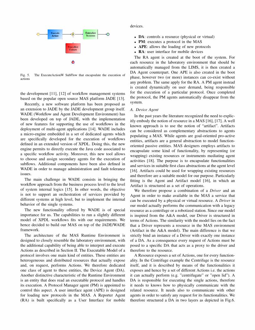
Fig. 5. The ExecuteActionW SubFlow that encapsulate the execution ofactions
the development [11], [12] of workflow management systemsbased on the popular open source MAS platform JADE [13].
Recently, a new software platform has been proposed asan extension to JADE by the JADE development group itself.WADE (Workflow and Agent Development Environment) hasbeen developed on top of JADE, with the implementationof new features for supporting the use of workflows in thedeployment of multi-agent applications [14]. WADE includesa micro-engine embedded in a set of dedicated agents whichare specifically developed for the execution of workflowsdefined in an extended version of XPDL. Doing this, the newengine permits to directly execute the Java code associated toa specific workflow activity. Moreover, this new tool allowsto choose and assign secondary agents for the execution ofsubflows. Additional components have been also defined inWADE in order to manage administration and fault toleranceissues.
The main challenge in WADE consists in bringing theworkflow approach from the business process level to the levelof system internal logics [15]. In other words, the objectiveis not to support an orchestration of services provided bydifferent systems at high level, but to implement the internalbehavior of the single systems.
The new functionality offered by WADE is of specialimportance for us. The capabilities to run a slightly differentmodel of XPDL workflows fits with our requirements. Wehence decided to build our MAS on top of the JADE/WADEframework.
The architecture of the MAS Runtime Environment isdesigned to closely resemble the laboratory environment, withthe additional capability of being able to interpret and executeActions as described in Section II. The Executable Model of aprotocol involves one main kind of entities. These entities areheterogeneous and distributed resources that actually exposeand, on request, performs Actions. We therefore dedicatedone class of agent to these entities, the Device Agent (DA).Another distinctive characteristic of the Runtime Environmentis an entity that does read an executable protocol and handlesits execution. A Protocol Manager agent (PM) is appointed tocontrol this aspect. A user interface agent (APE) is designedfor loading new protocols in the MAS. A Reporter Agent(RA) is built specifically as a User Interface for mobile
devices.
• DA: controls a resource (physical or virtual)• PM: executes a protocol in the MAS• APE: allows the loading of new protocols• RA: user interface for mobile devicesThe RA agent is created at the boot of the system. For
each resource in the laboratory environment that should beautomatically managed from the LIMS, it is then created aDA Agent counterpart. One APE is also created in the bootphase, however two (or more) instances can co-exist withoutany problem. The same apply for the RA. A PM agent insteadis created dynamically on user demand, being responsiblefor the execution of a particular protocol. Once completedthe protocol, the PM agents automatically disappear from thesystem.
A. Device Agent
In the past years the literature recognized the need to explic-itly embody the notion of resource in a MAS [16], [17]. A wellknown approach is to use the notion of “artifact”. Artifactscan be considered as complementary abstractions to agentspopulating a MAS. While agents are goal-oriented pro-activeentities, artifacts are a general abstraction to model function-oriented passive entities. MAS designers employs artifacts toencapsulate some kind of functionality, by representing (orwrapping) existing resources or instruments mediating agentactivities [18]. The purpose is to encapsulate functionalitiesand services in suitable first class abstractions at the agent level[16]. Artifacts could be used for wrapping existing resourcesand therefore are a suitable model for our purpose. Particularlyfitting is the Agent and Artifact model [16], in which anArtifact is structured as a set of operations.
We therefore propose a combination of a Driver and anAgent in order to make available in the MAS a service thatcan be executed by a physical or virtual resource. A Driver inour model actually performs the communication with a legacyresource as a centrifuge or a robotized station. Since our modelis inspired from the A&A model, our Driver is structured interms of Actions. The similarity with the model lies on the factthat a Driver represents a resource in the MAS environment(Artifact in the A&A model). The main difference is that westrictly bind an instance of a Driver with exactly one instanceof a DA. As a consequence every request of Actions must beposed to a specific DA that acts as a proxy to the driver andtherefore to the resource.
A Resource exposes a set of Actions, one for every function-ality. In the Centrifuge example the Centrifuge is the resourceitself, and it is described by means of the functionalities itexposes and hence by a set of different Actions i.e. the actionsit can actually perform (e.g. ”centrifugate” or ”open lid”). ADA is responsible for executing the single actions, thereforeit needs to knows how to physically communicate with therelated resource. It needs also to communicate with otheragents in order to satisfy any request for its functionalities. Wetherefore structured a DA in two layers as depicted in Fig.6.
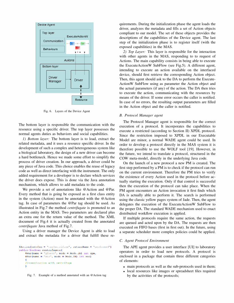
Fig. 6. Layers of the Device Agent
The bottom layer is responsible the communication with theresource using a specific driver. The top layer possesses thenormal agents duties as behaviors and social capabilities.
1) Bottom layer: The bottom layer is to load, extract therelated metadata, and it uses a resource specific driver. In thedevelopment of such a complex and heterogeneous system likea biological laboratory, the design of a new driver can becomea hard bottleneck. Hence we made some effort to simplify theprocess of driver creation. In our approach, a driver could beany piece of Java code. This choice enables the reuse of legacycode as well as direct interfacing with the instrument. The onlyadded requirement for a developer is to declare which servicesthe driver does expose. This is done via the Java annotationmechanism, which allows to add metadata to the code.
We provide a set of annotations like @Action and @Par.Every method that is going be exposed as a first class entityin the system (Action) must be annotated with the @Actiontag. In case of parameters the @Par tag should be used. Asillustrated in Fig.7 the method centrifugate is promoted to anAction entity in the MAS. Two parameters are declared plusan extra one for the return value of the method. The XMLdocument of Fig.4 it is actually created from the annotatedcentrifugate Java method of Fig.7.
Using a driver manager the Device Agent is able to loadand extract the metadata for a driver that fulfill these re-
Fig. 7. Example of a method annotated with an @Action tag
quirements. During the initialization phase the agent loads thedriver, analyzes the metadata and fills a set of Action objectscompliant to our model. The set of these objects provides thedescriptions of the capabilities of the Device agent. The laststep of the initialization phase is to register itself (with theexposed capabilities) in the MAS.
2) Top Layer: This layer is responsible for the interactionwith other agents in the MAS, responding to to request ofActions. The main capability consists in being able to executethe ExecuteActionW SubFlow (see Fig.5). A different agent,intending to execute an action available on the interfaceddevice, should first retrieve the corresponding Action object.Then, this agent should ask to the DA to perform the Execute-ActionW SubFlow using as parameter the Action object andthe actual parameters (if any) of the action. The DA then triesto execute the action, communicating with the resources bymeans of the driver. If some error occurs the caller is notified.In case of no errors, the resulting output parameters are filledin the Action object and the caller is notified.
B. Protocol Manager agent
The Protocol Manager agent is responsible for the correctexecution of a protocol. It incorporates the capabilities toexecute a restricted (according to Section II) XPDL protocol.Since the restriction imposed to XPDL in our ExecutableModel are minor, a normal WADE agent could be used. Inorder to develop a protocol directly in the MAS system it istherefore possible to use the WOLF tool [19]. However, inthe future, we intend to translate a protocol, structured in theCOW meta-model, directly in the underlying Java code.
On the launch of a new protocol a new PM is created. Thefirst step performed by a PM is to check if the protocol can runon the current environment. Therefore the PM tries to verifythe existence of every Action used in the protocol before ac-tually starting the execution. Only if that control is successfulthen the execution of the protocol can take place. When thePM agent encounters an Action invocation it first finds whichDA is actually able to perform it. The search is performedusing the classic yellow pages system of Jade. Then, the agentdelegates the execution of the ExecuteActionW SubFlow tothe proper DA. The standard WADE mechanism used to enactdistribuited workflow execution is applied.
If multiple protocols require the same action, the requestsare queued and acted upon by the DA. The requests are thenexecuted on FIFO bases (first in first out). In the future, usinga separate scheduler more complex policies could be applied.
C. Agent Protocol Environment
The APE agent provides a user interface [UI] to laboratoryoperators in order to load new protocols. A protocol isenclosed in a package that contain three different categoriesof elements:
• main protocols as well as the sub-protocols used in them;• local resources like images or spreadsheet files required
by the activities of the protocols;
• specific external libraries used to obtain some extrafeature like PDF documents generation.
APE loads a package and does visualize the content to theoperator. It then extracts all the resources and does deploythem into the runtime system. It is also responsible for creatinga new PM agent and to charge it with the execution of theloaded protocol.
D. Reporter Agent
A Reporter Agent has been built specifically to handlerequests from mobile devices that provide GUIs to laboratoryoperators. We currently support ANDROID [20] based mobiledevices using the peer-to-peer approach proposed by [21].
The RA is able to query the system and to provide informa-tion about the state of a sample processed in the laboratory.It interacts with the other agents of the runtime system andqueries the database in order to determine detailed informationlike:
• the customer order that activate the laboratory analysis;• the type of the biological analysis in which the sample is
involved;• the current phase of processing reached by the sample;• the relationship with other samples produced in the
laboratory for the same customer order.Finally, after collecting all pieces of information, the RA is
able also to produce a report and to send it to the operator’sGUI on its mobile device.
IV. A DEMO CASE STUDY
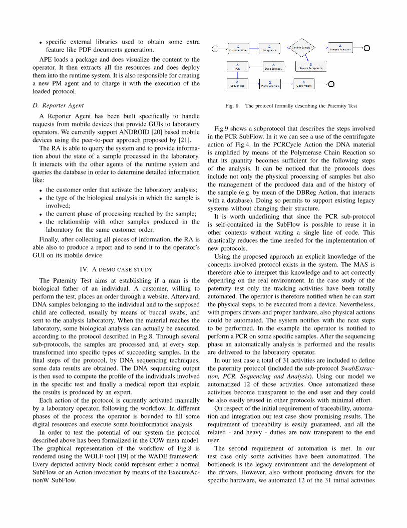
The Paternity Test aims at establishing if a man is thebiological father of an individual. A customer, willing toperform the test, places an order through a website. Afterward,DNA samples belonging to the individual and to the supposedchild are collected, usually by means of buccal swabs, andsent to the analysis laboratory. When the material reaches thelaboratory, some biological analysis can actually be executed,according to the protocol described in Fig.8. Through severalsub-protocols, the samples are processed and, at every step,transformed into specific types of succeeding samples. In thefinal steps of the protocol, by DNA sequencing techniques,some data results are obtained. The DNA sequencing outputis then used to compute the profile of the individuals involvedin the specific test and finally a medical report that explainthe results is produced by an expert.
Each action of the protocol is currently activated manuallyby a laboratory operator, following the workflow. In differentphases of the process the operator is bounded to fill somedigital resources and execute some bioinformatics analysis.
In order to test the potential of our system the protocoldescribed above has been formalized in the COW meta-model.The graphical representation of the workflow of Fig.8 isrendered using the WOLF tool [19] of the WADE framework.Every depicted activity block could represent either a normalSubFlow or an Action invocation by means of the ExecuteAc-tionW SubFlow.
Fig. 8. The protocol formally describing the Paternity Test
Fig.9 shows a subprotocol that describes the steps involvedin the PCR SubFlow. In it we can see a use of the centrifugateaction of Fig.4. In the PCRCycle Action the DNA materialis amplified by means of the Polymerase Chain Reaction sothat its quantity becomes sufficient for the following stepsof the analysis. It can be noticed that the protocols doesinclude not only the physical processing of samples but alsothe management of the produced data and of the history ofthe sample (e.g. by mean of the DBReg Action, that interactswith a database). Doing so permits to support existing legacysystems without changing their structure.
It is worth underlining that since the PCR sub-protocolis self-contained in the SubFlow is possible to reuse it inother contexts without writing a single line of code. Thisdrastically reduces the time needed for the implementation ofnew protocols.
Using the proposed approach an explicit knowledge of theconcepts involved protocol exists in the system. The MAS istherefore able to interpret this knowledge and to act correctlydepending on the real environment. In the case study of thepaternity test only the tracking activities have been totallyautomated. The operator is therefore notified when he can startthe physical steps, to be executed from a device. Nevertheless,with propers drivers and proper hardware, also physical actionscould be automated. The system notifies with the next stepsto be performed. In the example the operator is notified toperform a PCR on some specific samples. After the sequencingphase an automatically analysis is performed and the resultsare delivered to the laboratory operator.
In our test case a total of 31 activities are included to definethe paternity protocol (included the sub-protocol SwabExtrac-tion, PCR, Sequencing and Analysis). Using our model weautomatized 12 of those activities. Once automatized theseactivities become transparent to the end user and they couldbe also easily reused in other protocols with minimal effort.
On respect of the initial requirement of traceability, automa-tion and integration our test case show promising results. Therequirement of traceability is easily guaranteed, and all therelated - and heavy - duties are now transparent to the enduser.
The second requirement of automation is met. In ourtest case only some activities have been automatized. Thebottleneck is the legacy environment and the development ofthe drivers. However, also without producing drivers for thespecific hardware, we automated 12 of the 31 initial activities
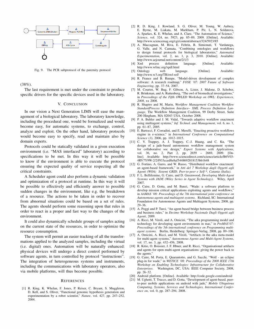
Fig. 9. The PCR subprotocol of the paternity protocol
(38%).The last requirement is met under the constraint to produce
specific drivers for the specific devices used in the laboratory.
V. CONCLUSION
In our vision a Next Generation LIMS will ease the man-agement of a biological laboratory. The laboratory knowledge,including the procedural one, would be formalized and wouldbecome easy, for automatic systems, to exchange, control,analyze and exploit. On the other hand, laboratory protocolswould become easy to specify, read and maintain also bydomain experts.
Protocols could be statically validated in a given executionenvironment (i.e. “MAS interfaced” laboratory) according tospecifications to be met. In this way it will be possibleto know if the environment is able to execute the protocolensuring the expected quality of service respecting all thecritical constraints.
A Scheduler agent could also perform a dynamic validationand optimization of a protocol at runtime. In this way it willbe possible to effectively and efficiently answer to possiblesudden changes in the environment, like e.g. the breakdownof a resource. The actions to be taken in order to recoverfrom abnormal situations could be based on a set of rules.The agents should perform some reasoning upon that rules inorder to react in a proper and fast way to the changes of theenvironment.
It could also dynamically schedule groups of samples actingon the current state of the resources, in order to optimize theresource consumption.
The system will permit an easier tracking of all the transfor-mations applied to the analyzed samples, including the virtual(i.e. digital) ones. Automation will be naturally enhanced:physical devices will undergo a direct control performed bysoftware agents, in turn controlled by protocol “instructions”.The integration of heterogeneous systems and instruments,including the communications with laboratory operators, alsovia mobile platforms, will thus become possible.
REFERENCES
[1] R. King, K. Whelan, F. Jones, P. Reiser, C. Bryant, S. Muggleton,D. Kell, and S. Oliver, “Functional genomic hypothesis generation andexperimentation by a robot scientist,” Nature, vol. 427, pp. 247–252,2004.
[2] R. D. King, J. Rowland, S. G. Oliver, M. Young, W. Aubrey,E. Byrne, M. Liakata, M. Markham, P. Pir, L. N. Soldatova,A. Sparkes, K. E. Whelan, and A. Clare, “The Automation of Science,”Science, vol. 324, no. 5923, pp. 85–89, 2009. [Online]. Available:http://www.sciencemag.org/cgi/content/abstract/324/5923/85
[3] A. Maccagnan, M. Riva, E. Feltrin, B. Simionati, T. Vardanega,G. Valle, and N. Cannata, “Combining ontologies and workflowsto design formal protocols for biological laboratories,” AutomatedExperimentation, vol. 2, no. 1, p. 3, 2010. [Online]. Available:http://www.aejournal.net/content/2/1/3
[4] Xml process definition language. [Online]. Available:http://www.wfmc.org/xpdl.html
[5] Ontology web language. [Online]. Available:http://www.w3.org/TR/owl-ref/
[6] R. France and B. Rumpe, “Model-driven development of complexsoftware: A research roadmap,” FOSE ’07: 2007 Future of SoftwareEngineering, pp. 37–54, 2007.
[7] M. Courtot, W. Bug, F. Gibson, A. Lister, J. Malone, D. Schober,R. Brinkman, and A. Ruttenberg, “The owl of biomedical investigations,”in Proceedings of the Fifth OWLED Workshop on OWL: Experiences,2008, xx 2008.
[8] R. Shapiro and M. Marin, Workflow Management Coalition WorkflowStandardProcess Definition Interface– XML Process Definition Lan-guage, The Workflow Management Coalition, 99 Derby Street, Suite200 Hingham, MA 02043 USA, October 2008.
[9] P. A. Buhler and J. M. Vidal, “Towards adaptive workflow enactmentusing multiagent systems,” Inf. Technol. and Management, vol. 6, no. 1,pp. 61–87, 2005.
[10] E. Bartocci, F. Corradini, and E. Merelli, “Enacting proactive workflowsengine in e-science,” in International Conference on ComputationalScience (3), 2006, pp. 1012–1015.
[11] C. V. Trappey, A. J. Trappey, C.-J. Huang, and C. Ku, “Thedesign of a jade-based autonomous workflow management systemfor collaborative soc design,” Expert Systems with Applications,vol. 36, no. 2, Part 2, pp. 2659 – 2669, 2009. [On-line]. Available: http://www.sciencedirect.com/science/article/B6V03-4RV7Y9W-2/2/f933cced0e8af5448692818153bb1648
[12] G. Fortino, A. Garro, and W. Russo, “Distributed workflow enactment:an agent-based framework,” in Atti del 7 Workshop dagli Oggetti agliAgenti (WOA) Sistemi GRID, Peer-to-peer e Self-*, Catania (Italia).
[13] F. L. Bellifemine, G. Caire, and D. Greenwood, Developing Multi-AgentSystems with JADE (Wiley Series in Agent Technology). Wiley, April2007.
[14] G. Caire, D. Gotta, and M. Banzi, “Wade: a software platform todevelop mission critical applications exploiting agents and workflows,”in AAMAS ’08: Proceedings of the 7th international joint conference onAutonomous agents and multiagent systems. Richland, SC: InternationalFoundation for Autonomous Agents and Multiagent Systems, 2008, pp.29–36.
[15] A. Poggi and P. Turci, “An agent-based bridge between business processand business rules,” in Decimo Workshop Nazionale Dagli Oggetti agliAgenti, 2009.
[16] A. Ricci, M. Viroli, and A. Omicini, “The a&a programming model andtechnology for developing agent environments in mas,” in ProMAS’07:Proceedings of the 5th international conference on Programming multi-agent systems. Berlin, Heidelberg: Springer-Verlag, 2008, pp. 89–106.
[17] A. Omicini, A. Ricci, and M. Viroli, “Artifacts in the a&a meta-modelfor multi-agent systems,” Autonomous Agents and Multi-Agent Systems,vol. 17, no. 3, pp. 432–456, 2008.
[18] R. Kitio, O. Boissier, J. F. Hbner, and R. Ricci, “Organisational artifactsand agents for open multi-agent organisations: giving the power back tothe agents.”
[19] G. Caire, M. Porta, E. Quarantotto, and G. Sacchi, “Wolf - an eclipseplug-in for wade,” in WETICE ’08: Proceedings of the 2008 IEEE 17thWorkshop on Enabling Technologies: Infrastructure for CollaborativeEnterprises. Washington, DC, USA: IEEE Computer Society, 2008,pp. 26–32.
[20] Android platform. [Online]. Available: http://code.google.com/android[21] M. Ughetti, T. Trucco, and D. Gotta, “Development of agent-based, peer-
to-peer mobile applications on android with jade,” Mobile UbiquitousComputing, Systems, Services and Technologies, International Confer-ence on, vol. 0, pp. 287–294, 2008.