Embed Size (px)
Citation preview
A Multi-Material Projection Stereolithography System for Manufacturing
Programmable Negative Poisson’s Ratio Structures
Da Chen
Thesis submitted to the faculty of the Virginia Polytechnic Institute and
State University in partial fulfillment of the requirement for the degree of
Master of Science
In
Mechanical Engineering
Xiaoyu Zheng, Chair
Alfred L. Wicks
Zhenyu Kong
December 12, 2016
Blacksburg, Virginia
Keywords: Additive Manufacturing, Stereolithography, multi-material, auxetic
structure, Poisson’s ratio

A Multi-Material Projection Stereolithography System for Manufacturing
Programmable Negative Poisson’s Ratio Structures
Da Chen
ABSTRACT
Digital light Projection based Additive Manufacturing (AM) enables fabrication of
complex three-dimensional (3D) geometries for applications ranging from rapid
prototyping jet parts to scaffolds for cell cultures. Despite the ability in producing
complex, three-dimensional architectures, the state of art DLP AM systems is
limited to a single homogenous photo-polymer and it requires a large volume of resin
bath to begin with. Extensible Multi-material Stereolithography (EMSL) is a novel
high-resolution projection stereolithography system capable of manufacturing
hybrid 3D objects. This system provides new capabilities, allowing more flexible
design criteria through the incorporation of multiple feedstock materials throughout
the structure. With EMSL manufacturing ability, multi-material programmable
negative Poisson’s ratio honeycomb reentrant structures are realized.
Researchers have been studying auxetic structures over decades, the mechanical
property control of auxetic structure mainly relies on geometry design in previous
studies. Now with the help of EMSL system, other design variables associated with
auxetic structures, such as material properties of local structural members, are added
into design process. The additional variables are then proved to have significant
effects on the material properties of the auxetic structures. The ability to accurately
manufacture multi-material digital design will not only allow for novel mechanical
and material researches in laboratory, but also extend the additive manufacturing
technology to numerous future applications with characteristics such as multiple
electrical, electromechanical and biological properties. The design and optimization
of EMSL system realizes novel structures have not been producible, therefore it will
stimulate new possibilities for future additive manufacturing development.

A Multi-Material Projection Stereolithography System for Manufacturing
Programmable Negative Poisson’s Ratio Structures
Da Chen
GENERAL AUDIENCE ABSTRACT
Since 1970s, stereolithography, one of the most commonly known additive
manufacturing techniques nowadays, has been improving the ability we make things.
Through the controllable and repeatable photo-polymerization process,
stereolithography can manufacture three-dimensional (3D) physical objects with
fast speed, high accuracy and highly detailed surface finish. Today,
stereolithography is already widely used in various rapid prototyping and
manufacturing areas including dental products, jewelry prototypes, structural and
tooling components. While latest researches continuously push its resolution to
smaller scale or wider areas, this process is still limited to single material
manufacturing.
To go beyond this manufacturing limitation, this thesis reports an Extensible Multi-
material Stereolithography (EMSL) system. This system takes advantages of the
sequential projections from a digital light modulator, combined with several low-
cost while efficient mechatronics components to enable printing at least two types
of materials with distinct colors or mechanical properties. With the multi-material
printing capability from EMSL, novel multi-material 3D auxetic structures, which
have only been theoretical concepts, are successfully manufactured and tested. The
reliability of EMSL process and properties of the new materials are investigated
with experiments and numerical calculations. The system can be further extended
to print multiple feedstock materials into one complex architectural assembly.
By realizing multi-material manufacturing capability, EMSL has broaden the
potential applications of additive manufacturing and it will enable the development
of multiple research and application areas including metamaterial, micro-electro-
mechanical systems and bio-medical implants.

iv
Acknowledgement
I would like to thank my advisor Dr. Xiaoyu Zheng for his guidance and generous
support, thank all my committee members for helping me go through the completion
of the Master’s degree at Virginia Tech.
Great appreciations are also due to the Virginia Tech an DOE Lawrence Livermore
National Laboratory for providing funding for my research topic. I will always be
grateful for this invaluable learning opportunity.
I would also like to thank Zhi Chai for helping with analytical prediction utilized in
this work, and Huachen Cui for hands-on assistance during experiments, as well as
the other members of Advanced Manufacturing and Metamaterials Laboratory
(AMML) who have assisted much of the work that need great research skills and
everlasting enthusiasm: Panni Zheng, Yihan Wang, Kyle Flynn, Aditya Shenoy and
Griffin Hyde.
To all of my great friends in Blacksburg, your love and generosity help me overcome
times of difficulty and pressure.
Disclaimer
This work was conducted under the auspices of Advanced Manufacturing and
Metamaterial Laboratory, Department of Mechanical Engineering, Virginia Tech
and DOE Lawrence Livermore National Laboratory under Contract DE-AC52-
07NA27344. I have signed a non-disclosure agreement including the thesis content
with Virginia Tech prior to releasing the thesis to public and future publications.
Virginia Tech and LLNL retain ownership of all intellectual property associated with
this work including IP applications (No: 62/313,954 No:14/943,873 No:14/919,441)

v
Table of Contents
Chapter 1: Introduction .............................................................................................. 1
1.1 Literature review ................................................................................................................... 1
1.2 Motivations and EMSL system ............................................................................................. 8
1.3 Objective ............................................................................................................................... 8
1.4 Organization .......................................................................................................................... 9
Chapter 2: System Design ........................................................................................10
2.1 Overview ............................................................................................................................. 10
2.1.1 Print Mechanism of EMSL system ............................................................................................................ 10
2.1.2 System schematic ....................................................................................................................................... 11
2.2 Mechanical Design layout ................................................................................................... 14
2.2.1 X, Y and Z axis motion control method ..................................................................................................... 14
2.2.2 X axis cartridge .......................................................................................................................................... 17
2.2.3 Y axis material jet-head and z axis elevator ............................................................................................... 23
2.2.4 Liquid delivery hardware ........................................................................................................................... 26
2.3 Optical Design layout .......................................................................................................... 28
2.4 Software Design layout ....................................................................................................... 29
2.4.1 System operating logic ............................................................................................................................... 29
2.4.2 Arduino, LabVIEW and Smart Motor Interface ........................................................................................ 31
Chapter 3: Photo-polymer resin ...............................................................................33
3.1 Tunable Young’s modulus material .................................................................................... 33
3.2 Material composition........................................................................................................... 34
3.3 Mechanical properties ......................................................................................................... 35
Chapter 4: Lattice design .........................................................................................37
4.1 NPR Structure ..................................................................................................................... 37
4.2 Honeycomb re-entrant structure .......................................................................................... 37
4.3 Idealized re-entrant structure ............................................................................................... 40

vi
Chapter 5: Analytical solution of multi-material honeycomb structure ..................42
5.1 Force and displacement analysis with respect to geometry ................................................ 42
5.2 Calculation of re-entrant strut displacement 𝚫𝐮 and 𝚫𝐯 ..................................................... 46
5.3 Poisson’s ratios in z direction under compressive stress..................................................... 49
5.4 FEA validation on analytical solution ................................................................................. 50
Chapter 6: Results and conclusion ...........................................................................53
6.1 Multi-material honeycomb re-entrant lattice....................................................................... 53
6.2 Tensile test on multi-material honeycomb re-entrant samples............................................ 55
6.3 Results and discussions ....................................................................................................... 57
6.4 Idealized re-entrant lattice sample....................................................................................... 59
6.5 Limitations of EMSL system .............................................................................................. 60
6.6 Conclusion ........................................................................................................................... 63
References ................................................................................................................64
vii
List of Figures Figure 2-1. EMSL multi-material fabrication principle. ............................................................................. 11
Figure 2-2. Schematic illustration of the Extensible Multi-material Stereolithography system ................. 12
Figure 2-3. Simplified Logic flow of multi-material EMSL system........................................................... 14
Figure 2-4. 15-pin CAN cable for serial communication ........................................................................... 16
Figure 2-5. Aluminum fixture for system positioning ................................................................................ 17
Figure 2-6. Exploded view of X axis cartridge -- 10 individual parts ........................................................ 18
Figure 2-7. PDMS window on X axis cartridge .......................................................................................... 19
Figure 2-8.Micro-fluidic cleaning module on X axis cartridge .................................................................. 21
Figure 2-9. Extruding fins on X axis cartridge ........................................................................................... 22
Figure 2-10 Blow drying fan & air deflector assembled on x axis cartridge. ............................................. 22
Figure 2-11. Assembled and exploded view of Y axis cartridge ................................................................ 23
Figure 2-12. Micro-fluidic cleaning module on Y axis cartridge ............................................................... 25
Figure 2-13. Assembled and exploded view of Z axis cartridge ................................................................. 25
Figure 2-14. Optical design layout and major components ........................................................................ 28
Figure 2-15. Flowchart of EMSL building process .................................................................................... 30
Figure 2-16. EMSL user interface in LabVIEW ......................................................................................... 31
Figure 2-17. EMSL software logic chart .................................................................................................... 32

viii
Figure 3-1. Bridge test on FlexSL4 material ............................................................................................... 35
Figure 4-1. 3D honeycomb re-entrant structures. ....................................................................................... 38
Figure 4-2. 3D Idealized re-entrant unit cell ............................................................................................... 40
Figure 4-3. 3D tailored Idealized re-entrant structure ................................................................................. 41
Figure 5-1. Bi-material 3D honeycomb re-entrant lattice ........................................................................... 42
Figure 5-2. Unit cell loading condition ....................................................................................................... 44
Figure 5-3. Finite Element analysis of unit cell under infinite field assumption ........................................ 51
Figure 5-4. Analytical solution and finite element simulation comparison ................................................ 52
Figure 6-1. Honeycomb re-entrant design for tensile test ........................................................................... 54
Figure 6-2. Size information of manufactured multi-material honeycomb re-entrant lattice ..................... 54
Figure 6-3. multi-material honeycomb re-entrant lattice dog bone sample for tensile test ......................... 55
Figure 6-4. Method of Poisson’s ratio measurement .................................................................................. 56
Figure 6-5. Poisson’s ratio of multi-material honeycomb lattice samples with respect to strain ................ 57
Figure 6-6. Poisson’s ratio comparison, analytical prediction vs tensile test results .................................. 58
Figure 6-7. Idealized re-entrant lattice, (a) top view; (b) diagonal view .................................................... 60
Figure 6-8. One possible solution to nano-particle contamination ............................................................. 61
Figure 6-9. Optimal EMSL resolution demonstrated by multi-material octet lattice ................................. 62

ix
List of Tables
Table 2-1. Pump arrangement and operational details ................................................................................ 27
Table 3-1. Young’s modulus tunable material, FlexSL resin composition ................................................. 34
Table 3-2. Measured Young’s modulus of FlexSL series material ............................................................. 36
Table 6-1. Honeycomb re-entrant samples composition ............................................................................. 53
Table 6-2. Relative error of 10 experimental data ...................................................................................... 59

1
Chapter 1
1.Introduction
1.1 Literature review
Additive Manufacturing(AM) is a manufacturing technology that creates objects rapidly with the
help of Computer Aided Design (CAD) files. Different from traditional manufacturing method,
additive manufactured models are usually stacked out by a serial of planer slices which are
produced by processing wanted CAD designs with mathematical code.
Stereolithography, commonly known as SLA, is one of the most applied forms of AM technology.
Stereolithography researches were first appeared in 1970s, then in 1986 Chuck Hull patterned a
technique capable of stacking planer cross-sectional geometries, in the direction of bottom to top,
into a complete physical model. The unique material in Hull’s pattern was ultraviolet sensitive
photopolymer. This technology was named and coined as the term “Stereolithography”. In the
same year, Hull also founded 3D system Inc., currently known as the first and biggest 3D printing
enterprise.
After decades of development, stereolithography now can be described as an Additive
Manufacturing process that hardening or curing photopolymer resin layer by layer into actual

2
objects. The light source, usually using ultraviolet light, provides essential energy for stimulating
and maintaining photo-polymerization reaction in which smaller molecules bond and form cross-
linking polymer molecular chains. The energy source of photo-polymerization reaction can be a
laser beam or mask projection patterns. The laser beam moving trajectories or mask projection
patterns are pre-programmed by mathematical code and then applied onto the surface of
photopolymer resin.
The logic flow of stereolithography manufacturing process is usually demonstrated as following
steps [1]:
1. Create a CAD model, model can be surface or solid
2. Export the CAD model into particular file format, STL. for example
3. Repair model and add support structures
4. Set manufacturing parameters, such as layer height and exposure, slice processed model
5. Upload slice files and controlling information into stereolithography apparatus.
6. Run stereolithography apparatus.
7. Clean manufactured part and post-process, for example trim supports and post-curing.
Although sharing the above basic working procedures, stereolithography techniques can be
classified and sorted by several commonly accepted criteria.

3
In this thesis, the author lists two types of sorting criteria for stereolithography systems. First off,
the obvious moving direction of building platform. According to manufacturing direction,
stereolithography systems can be categorized into “Top down” and “Bottom up” configurations.
The second criterion is light source type. As mentioned previously, both laser beam and mask
projection pattern can be used as light source, and they are the so-called “Laser lithography” and
“photo-mask lithography”[2].
Details of “Top down” and “Bottom up” configurations are introduced first. In “Top down”
configuration, every layer is built on resin surface then the elevator sinks a layer thickness into
resin bath for following model layers. In the interval of layer change, some resin level-up step will
be needed such as a blade scraping across resin surface. The curing depth of every layer will be
designed to the extent that current layer can be combined with previous layers. As the elevator
sinking into resin bath, the CAD designed object forms under resin surface, and this is the so-
called “Top-down” process. The complete physical object is then cleaned in ethyl alcohol or
acetone bath for particular time, and then support-trimming or post curing process is conducted if
necessary.
The “Bottom-up” method is an alternative process for stereolithography system. Unlike “Top-
down” process, every layer in “Bottom-up” process is cured at the bottom of resin bath. To make
it possible, the bottom of resin bath needs to be ultraviolet light transparent and cannot stick with
the elevator after curing. The Carbon M1 Continuous Liquid Interface Production (CLIP)[3]
system is the most advanced example of “Bottom-up” system. To start a print job, the elevator first

4
descends onto the bottom of resin bath and gently touches the UV transparent window. The UV
projection cures the bottom layer to form a base then the elevator lifts continuously until the
physical object is produced. Careful manipulation of oxygen enables the forming of “dead zone”
on UV transparent window. In this “dead zone”, the photo-polymerization reaction terminates
somewhere, and give enough space for liquid resin to refill the cured gap.
Comparing “Top-down” to “Bottom-up” configurations, “Bottom-up” system only needs small
amount of resin to begin with, usually covering the ultraviolet window with photopolymer resin
will be good enough. This means less photopolymer resin will be required in “Bottom-up” system
than in “Top-down” system, and photopolymer resin is some relative expensive material.
Photopolymer is sensitive to oxygen in atmosphere and random light in environment, less feeding
amount of resin will reduce the waste of material which means degrading and permanently
solidification of resin.
According to the second sorting criterion previously mentioned, the type of light source,
stereolithography systems can also be categorized into “Laser lithography” and “photo-mask
lithography”.
A good example of “Laser lithography” system is the Form-2 SLA printer designed by formlabs.
The light source in Form-2 is 405nm laser beam. A set of optical components first manipulate laser
beam into ideal shape and a pair of high-speed galvanometers connected with mirror guide the
laser beam to move on the bottom of resin bath. From-2 is a “Bottom-up” configured system. The

5
moving speed, laser intensity, and moving trajectory of focused laser dot are critical parameters
for “Laser lithography” process[4]. Besides galvanometer scanning mirror, some “Laser
lithography” use X-Y plane stepper motors as the method to change the position of focused laser
dot[5], just like Fused Deposition Modeling (FDM) filament 3D printer.
The “photo-mask lithography” system is more straightforward in configuration. To make
changeable projection patterns, Liquid Crystal Display (LCD), Liquid crystal on Silicon (LcoS) or
Digital Light Processing (DLP) projection techniques can be used. The projection unit sits above
(Top-down) or beneath (Bottom-up) the resin bath and projects one pattern for the curing of each
layer. To simplify the explanation, every pixel in projection pattern can be imagined to have the
value of either “0” or “1”. “0” means light off, “1” means light on. The binary pattern enables resin
curing of particular area and remains the rest as liquid state.
Comparing “laser lithography” and “photo-mask lithography”, the latter technique needs less
building time and has higher system reliability because “photo-mask lithography” solidifies one
layer in a single step and doesn’t need any moving parts such as galvanometer scanning mirror.
Also, according to particular manufacturing requirements, “photo-mask lithography” can be easily
adjusted to the wanted pattern resolution or picture size. The “photo-mask lithography”
configuration is therefore versatile enough for research purposes.
Despite the ability in producing complex, three-dimensional architectures, the state of art DLP AM
systems have the following limitations: 1) It is limited to single homogenous photo-polymer; 2) It

6
requires a large volume of resin bath to begin with. In other word, DLP AM technology is not
capable of producing multi-material, complex, 3D high-resolution architecture with multiple
embedded material constituents.
On the other hand, multi-material 3D printing is a highly attractive technology for it extends the
potential application of additive manufacturing in many areas, ranging from rapid prototyping,
tissue engineering to meta-materials manufacturing. The multi-material manufacturing capability
can be realized by improving several existing AM technologies such as fused deposition modeling
(FDM), selective laser sintering (SLS), and SLA.
Fused deposition of multiple ceramics (FDMC), developed by W. Han etc.[6], is a multi-material
manufacturing system based on FDM schematic concept. FDMC is capable of multiple ceramic
actuators and sensors fabrication. The functional ceramic parts and composite components are
directly fabricated by green ceramic filaments, specially designed for FDMC system.
Multi-nozzle biopolymer deposition system, developed by S. Khalil etc.[7], is capable of
manufacturing 3D biopolymer tissue scaffolds for housing cells in tissue engineering research.
Khalil’s system works the same way as FDM printer does, scaffold geometry is directly formed
by deposition head and 3D motion system, but in order to deliver bio-compatible materials, the
regular heated nozzles are replaced with liquid pumping modules. The multi-nozzle biopolymer
deposition system consists of various type of micro-nozzles. These nozzles are used to deliver bio-
compatible polymers with various viscosity. With the help of accurate mechatronics components

7
and controlling software, multiple biopolymer deposition of cell scaffolds can be precisely
achieved by multi-nozzle biopolymer deposition system.
The Polyjet 3DP system is a commercial multi-material manufacturing system. The printing
material in Ployjet system is also ultraviolet photo-polymer, but the polymer is not curing by UV
patterns. The jetting head in Ployjet system acts as a nozzle in color printer. One layer of object
can be printed directly consisting of multiple types of photo-polymers, a uniform UV exposure
will then cure all material on that layer. The Ployjet 3DP is also involved in advanced material
researches such as randomly oriented multi material (ROMM) additive manufacturing[8], which
produces fiber reinforcement functional parts with better stiffness and geometry accuracy.
Mask-image-projection-based stereolithography (MIP-SL) system, developed by Zhou etc.[9], is
a multi-material fabrication system based on SLA technology. The material in MIP-SL is
ultraviolet photo-polymer and it is cured by UV patterns. To switch materials during the fabrication
process, a wheel system is designed in MIP-SL. Material cartridges, cleaning device and drying
units are fixed on the wheel system. Since MIP-SL is based on SLA, the printing accuracy is better
than the FDM based systems.

8
1.2 Motivations and EMSL system
After careful comparison of various multi-material AM system configurations, this thesis will
focus on the “Bottom-up photo-mask lithography” based additive manufacturing system, because
the printing speed and accuracy of SLA is required for author’s meta-material research.
This thesis presents a novel high-resolution projection stereolithography system, Extensible Multi-
material Stereolithography (EMSL) system, capable of manufacturing hybrid, multi-material 3D
objects. This system provides new capabilities, allowing more flexible design criteria through the
incorporation of multiple feedstock materials throughout the structure.
1.3 Objective
• Provide technical review about Stereolithography Additive manufacturing technology.
• Introduce the novel EMSL system in mechanical, optical and software details.
• Choose multi-material tunable negative Poisson’s ratio(NPR) lattice, honeycomb reentrant
structure to implement using EMSL system.
• Prepare photo-polymer resin with tunable Young’s modulus values.
• Demonstrate analytical equations for the Poisson’s ratio prediction of multi-material
honeycomb reentrant structure.
• Measure the Poisson’s ratio of EMSL manufactured honeycomb reentrant lattices, and compare

9
the experimental values with analytical prediction values.
1.4 Organization
For the following chapters in this thesis, Chapter 2 demonstrates detailed information about the
design of mechanical, optical and software sub-module in EMSL system. The emphasis of Chapter
3 is an introduction on special photo-polymer resin with tunable Young’s modulus functionality.
Chapter 4 discusses the different types of auxetic cellular structure and describe the design process
of honeycomb reentrant lattice. Chapter 5 goes through the analytical equations for Poisson’s ratio
prediction of multi-material honeycomb reentrant lattice. Finally, a discussion about results and
conclusion is given Chapter 6.

10
Chapter 2
2.System Design
2.1 Overview
2.1.1 Print Mechanism of EMSL system
EMSL (Extensible Multi-material Stereolithography) is a three-dimensional additive
manufacturing system based on “Bottom-up photo-mask lithography” stereolithography
configuration.
In order to understand the operating process of EMSL, the difference between single-material and
multi-material manufacturing process will first be considered. From a projection SLA point of
view, the cross-section of single-material object can be manufactured by a single exposure of
ultraviolet pattern. The manufacturing of multi-material object cross-section obviously requires
more efforts because it consists of parts with different material constituents. To produce a complete
multi-material layer, a practical solution for projection SLA is dividing a single layer into different
parts according to material type and manufacturing each part as single-material layer as shown in
Figure 2-1.

11
Figure 2-1. EMSL multi-material fabrication principle. A multi-material three dimensional model (a) is sliced into
layers and every single layer is fabricated sequentially corresponding to material type(b) and the structure is built
in a layer-by-layer sequence.
2.1.2 System schematic
Based on the above method, to fabricate a multi-material three dimensional object using EMSL,
every layer of object is first divided into parts with corresponding material[10]. A digital pattern
corresponding to particular material segment solidifies photopolymer resin surface with light
source of particular wavelength according to resin property. The light source stimulates a reaction
called polymerization that connecting the monomer molecules into larger molecular chains,
observed as solidification, within the contour of the projected pattern. The thickness of
manufactured layer is controlled by intensity of energy source, diameter of pixel dot, reaction time,
photo-initiator concentration and light penetration depth in resin which is determined by the
concentration of photo-absorber. The material is then changed and UV pattern cures the next
material segment, the process repeats after a complete layer of desired material combination is
finished. This complex layer by layer process stops until the desired number of layers have been
fabricated to form the complete 3D object.

12
Figure 2-2. Schematic illustration of the Extensible Multi-material Stereolithography system
Figure 2-2 describes the hardware setup used to realize the material switchover and layer stacking
procedure. The EMSL multi-material additive manufacturing technique presented here is highly
precise, extensible and cost efficient due its additive manufactured structural parts, both FDM and
SLA manufacturing method are employed, and low price mechatronics components such as 12-
Volt brush motor peristaltic pumps.
To verify the described concept, a working system has been successfully built. In the EMSL system,
a Digital Micromirror Device (DMD) based UV projector was used. The direct integration of a
commercial light engine can greatly simplify the system design.

13
The optical light path of EMSL consists of a pair of tube lens and beam splitter (Thorlabs). Multiple
projection parameters such as focal length, light intensity and distribution uniformity were adjusted
to get a quality projection pattern on the focal plane. The DMD chip resolution in EMSL is
1024x768 in pixels and profile size of projected pattern is set at 20mm x 15mm. Three linear
actuators from MOOG Inc. (L70 series linear actuator) are used as the elevator for driving Z axis
platform, motion controllers for driving X axis cartridge and material jet-head in Y axis
correspondingly. The linear actuators come with microcontroller in the integrated step motors. A
low cost Arduino micro-controller board and a Adafruit motor shield are used for controlling the
vibration motor in Z axis elevator, the fan on X axis cartridge and peristaltic pumps for liquid
delivery.
A simplified logic chart describing multi-material EMSL process is shown in Figure 2-3. To
increase the use efficiency of resin material, the material transition procedure is conducted in every
two layers rather than in every single layer. To achieve this special process, the EMSL system
arrange the manufacturing sequence of various material (material A and material B, for example)
as: A𝑖 − B𝑖 − 𝐵𝑖+1 − 𝐴𝑖+1 rather than the intuitive A𝑖 − B𝑖 − 𝐴𝑖+1 − 𝐵𝑖+1 sequence. Using this
method, less resin switchover time, less cleaning steps and less material consumption are required.
A multi-material EMSL system controlling software has been integrated using the LabVIEW
graphic programming language as the user interface with Arduino and Moog Smart Motor
Interface (SMI) as sub-systems under LabVIEW. All components and control software code are
with the Advanced Manufacturing and Metamaterials Laboratory.

14
Figure 2-3. Simplified Logic flow of multi-material EMSL system
2.2 Mechanical Design layout
2.2.1 X, Y and Z axis motion control method
To accurately move X, Y and Z axis cartridges in EMSL design, the author uses three MOOG
Animatics L70 series actuators to control the motions of print cartridge, brush unit and print
platform respectively. The specific length of three MOOG Animatics L70 actuators are given
below:
The X axis is MOOG Animatics L70, Stroke 300mm.
The Y axis is MOOG Animatics L70, Stroke 500mm.
The Z axis is MOOG Animatics L70, Stroke 200mm.

15
A MOOG L70 linear actuator is driven by a MOOG SmartMotor. Compared to regular stepper
motors, Moog Animatics SmartMotor is integrated with micro-controllers for driving motor and
countering encoder as the method of accurate motion control. Each SmartMotor is able to be a
slave or a master so that it can achieve efficient communication in a huge motor network. This
master-slave structure enables sequential motion of X, Y and Z axis, and the motion control
software is written in SMI interface, an MOOG produced integrated development environment.
The accuracy of SmartMotor L70 actuator is determined by SmartMotor moving accuracy and the
screw lead of transmission shaft. In L70 series, the theoretical accuracy is 800 encoder counts per
millimeter. Combined with a 5mm screw lead of transmission shaft, MOOG L70 actuator has
control accuracy of 6.25 microns. For EMSL applications, the minimum layer height required is
about 10 microns so SmartMotor is good enough for the research purpose.
The motor communication interface is comprised by two ports – 7 Pin Combo D-sub connector
and 15 Pin D-sub I/O. The 7 Pin Combo D-sub connector, linked together by daisy chain, is often
used for power supply and data transmission. The EMSL motion control command is uploaded
into SmartMotor micro controller through three serially connected daisy chain.
To realize the function of high speed communication between SmartMotors, a MOOG developed
protocol called Combitronics is used. Combitronics protocol operates over a standard “CAN”
(Controller Area Network) interface. Each SmartMotor connected to the CAN network shares all
information on the same pace and shares all processing resources and results transparently.

16
To enable Combitronic CAN communication, a CAN cable is required through the D-sub
connector on the top of the motor.
Figure 2-4. 15-pin CAN cable for serial communication
Above is a four-motor connection example, this CAN cable design is used in EMSL system. For
simplicity, the author canceled shield drain in standard design. There are only three actuators in
EMSL system, so one of CAN port on the cable is vacant.
The MOOG Animatics L70 series actuators come to be fully functional as X, Y and Z axis with
power cable, RS232 to USB adaptor, 7pin D-sub (for power, serial communication, and software
upload) and 15 pin D-sub (for CAN communication) connected.

17
Figure 2-5. Aluminum fixture, including U channel and optical bread, for system positioning
Three aluminum U channel stands are designed for X, Y, and Z axis fixtures, as shown in Figure
2-5. With Thorlabs MB2436, aluminum breadboard 24’’ x 36’’x1/2’’, ¼’’-20 taps, the relative
positions between aluminum bread board, aluminum U channel stands, and MOOG Animatics L70
series actuators are reliably determined.
2.2.2 X axis cartridge
The layer-by-layer printing process is conducted on X axis cartridge, through a UV transparent
window. In EMSL system, the X axis cartridge is manufactured by low-cost SLA printed parts.
Exploded view of x axis cartridge indicates that the whole assembly has a total of 10 components
as shown in Figure 2-6.

18
Figure 2-6. Exploded view of X axis cartridge -- 10 individual parts
Initial version of X axis cartridge is manufactured by FDM (Fused Deposition Modeling) 3D
printers, but the author then moved on with SLA manufacturing technology. X axis cartridge
directly contacts with large volume rate of ethanol, and ethanol is known to be one kind of liquid
with very low viscosity. Typical FDM made components have a characteristic parameter called
porous rate, and this rate is usually set to be around 50%. FDM printing process can also make
part with 100% printing density, but the later introduced thermal stress problem will damage the
geometry of printed parts.
To make the x axis cartridge ethanol-proof, and also to maintain the shape accuracy of designed
geometry to the maximum extend, the author then tried to used Autodesk Ember printer to
manufacture X axis cartridge. Autodesk Ember is a SLA 3D printer with X Y Z build volume of
64mm x 40mm x 134mm. To adapt x axis cartridge into Ember manufacturing ability, a complete
cartridge is then divided into 10 pieces.

19
According to the print mechanism described above, x axis cartridge should have multiple functions.
The first major function of x axis is serving as a printing interface. This function is realized by
PDMS window in EMSL system shown in Figure 2-7. Good PDMS window should have the
characteristic of high UV light transmission rate, high separation function durability, active oxygen
inhibition phenomenon[11, 12] and accurate horizontal levelness.
Figure 2-7. PDMS window on X axis cartridge
PDMS (Polydimethylsiloxane), commonly used as elastomer, can be sorted into polymeric
organosilicon compounds group which is widely known as silicones. And PDMS is the most
widely used silicone polymer for its convenient preparation process. With particular thickness of
oxygen inhibition layer on PDMS surface, usually several microns[11], photo-polymerization
reaction will terminate on PDMS vicinity, thus elevator and print platform can separate easily.
This advantage of PDMS makes it suitable as the interface of photo-polymerization reaction.
However, the Young’s modulus of PDMS material is fairly small, around 3 MPa. This means,
PDMS will have large deformation under minor load force. To make the printing platform stiffer

20
and keep it to be UV transparent, a thin PDMS layer is coated onto coverslip which is assembled
into coverslip notch marked by red dash line in above figure.
A major challenge in PDMS window design is that SLA printed part cannot be bonded firmly with
PDMS, because of the inert reaction properties between PDMS and photo-polymer resin. To
address this problem, two slots are designed into PDMS window, pointed out by blue arrow in
Figure 2-7. Liquid-state PDMS material will flow into the PDMS slots. After the PDMS in slots
is cured, it provides physical grabbing force to lock PDMS and photo-polymer produced part
firmly together.
The second major function of x axis cartridge is cleaning printed part. Cleaning process between
layers is the critical problem of multi-material SLA 3D printing. For example, if the first layer in
one model is manufactured by material A, and the second layer is designed to made by material B,
a thorough cleaning process is then required between first and second layer for multi-material SLA
3D printing.
MIP-SL multi-material SLA technology, developed by Zhou etc.[9], uses a reservoir to store
ethanol for the washing process. However, according to author’s observation, a tank of ethanol is
easily contaminated by small amount of resin. For example, if blue and transparent resin are used
as material A and material B in multi-material model, a tank of cleaning ethanol will become blue
and contaminate the later transparent layers. To improve cleaning efficiency and material contrast,
an open flow wash unit is specially designed, as shown in Figure 2-8.

21
Figure 2-8. (a)Micro-fluidic cleaning module on X axis cartridge;(b) left-view draft of module, ethanol marked in
blue
The author designed a series of micro-fluidic channels to increase the outcome pressure of ethanol
and extend the cleaning area. There are two columns of micro slots, and each outlet slot is 0.16mm
x 0.8 mm in size. Used ethanol will not be stored in wash tank because there are only three walls
on the wash tank. The surface facing upwards is designed to be flat in order to protect the printed
part from any physical damage.
The third major function of X axis cartridge is PDMS brush cleaning. As will be introduced below,
a PDMS bush unit is designed to clean the remaining resin after a round of curing process.
Although PDMS material has the advantage of large contact angle corresponding to photo-polymer
resin, liquid-state resin can still hang on PDMS brush if no other cleaning process is conducted.
To improve the PDMS brush cleaning process, three extruding fins are designed on X axis
cartridge, as shown in Figure 2-9. This design enables physical cleaning procedure of PDMS brush.
For each cleaning procedure, the PDMS brush is scraped twice by the fins before it cleans the
PDMS window, and one more scrape after it clean the PDMS window.
22
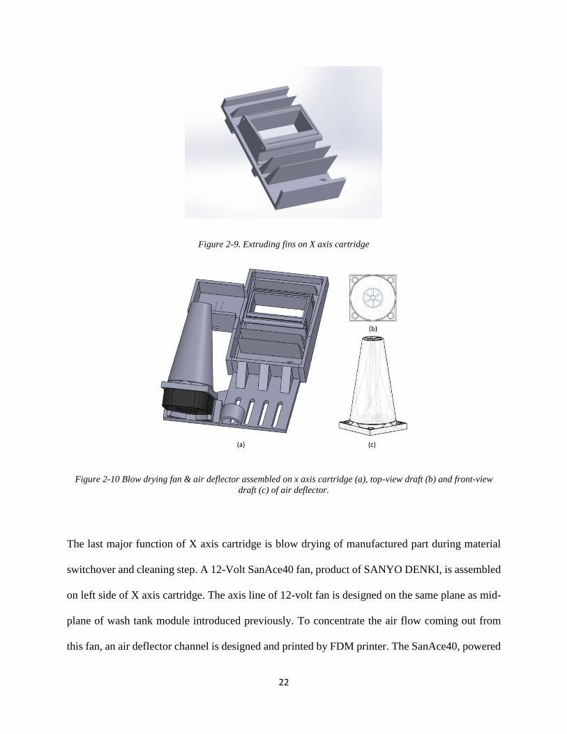
Figure 2-9. Extruding fins on X axis cartridge
Figure 2-10 Blow drying fan & air deflector assembled on x axis cartridge (a), top-view draft (b) and front-view
draft (c) of air deflector.
The last major function of X axis cartridge is blow drying of manufactured part during material
switchover and cleaning step. A 12-Volt SanAce40 fan, product of SANYO DENKI, is assembled
on left side of X axis cartridge. The axis line of 12-volt fan is designed on the same plane as mid-
plane of wash tank module introduced previously. To concentrate the air flow coming out from
this fan, an air deflector channel is designed and printed by FDM printer. The SanAce40, powered

23
by DC power supply, works at 12 volts and 1.52 A. Besides red and black power lines, a pair of
sensor and control lines are connected to Arduino motor shield for speed control and monitoring.
The maximum air flow rate from SanAce40 is around 0.0138m3/𝑠 and the velocity of flow can
reach around 20m/s at deflector terminal which enables part drying within 5s.
After all of the 10 components of x axis cartridge are manufactured by Ember printer, they are
glued together by high-initiator-content PEGDA resin. Special attentions should be paid to micro-
channel outlet, PEGDA resin can easily permeate into these channels and block them off. After
changing manufacturing method from FDM to SLA, the 10 individual parts can keep their
designed geometry with excellent quality.
2.2.3 Y axis material jet-head and z axis elevator
The main function of Y axis material jet-head is cleaning PDMS window and applying material
on print platform. There are four components in Y axis material jet-head assembly.
Figure 2-11. Assembled and exploded view of Y axis cartridge

24
In Figure 2-11 above, the brown component is Y axis fixture which attaches onto Y axis linear
actuator cartridge. To reduce the manufacturing cost and make component upgrade easy, this Y
axis fixture is made by FDM 3D printer.
The lower right corner component in exploded view is material jetting tube. Although our material
jetting tubes are capable of delivering two feedstock materials, our ‘EMSL’ (Extensible Multi-
material Stereolithography) can simply alter the jetting tube design to extend the number of
material type. Compared to other multi-material system configuration, such as MIP-SL wheel
system, EMSL is much more extensible according to the concept of changeable jetting tube.
The lower middle component in exploded view is PDMS brush. When Y axis cartridge swipe
across the X axis cartridge, the PDMS brush can easily wipe away all the waste resin remaining
on print platform and meanwhile cleaned by extruding fins on X axis cartridge.
The lower left corner component in exploded view is another micro-fluidic channel designed for
pumping ethanol onto print platform. The author observed that, to wipe away regular resin, such
as Autodesk Ember series, PDMS brush is efficient enough. The author has also tried ceramic
powder and silica carbide as functional additives in resin. The diameter of ceramic powder and
silica carbide are 100 nanometers and 10 nanometers respectively. Without appropriate lubrication
before PDMS brush swiping the print platform, these nano-particles can stick onto PDMS window
and affect the following print procedure. To solve this problem, a micro-fluidic channel is added
in front of PDMS brush, shown as lower left part in Figure 2-11. The slot size on micro-fluidic

25
channel is 0.6 mm x 0.8 mm each, shown in Figure 2-12. During every window cleaning procedure,
the Y axis micro-channel jets 12 columns of ethanol onto waste rein surface at the flow velocity
of 0.7m/s. The jetted ethanol will mix with resin and lower its viscosity. Based on observation,
when resin viscosity is reduced, the nano-particles can be brushed by PDMS scrape easier.
Figure 2-12. Micro-fluidic cleaning module on Y axis cartridge
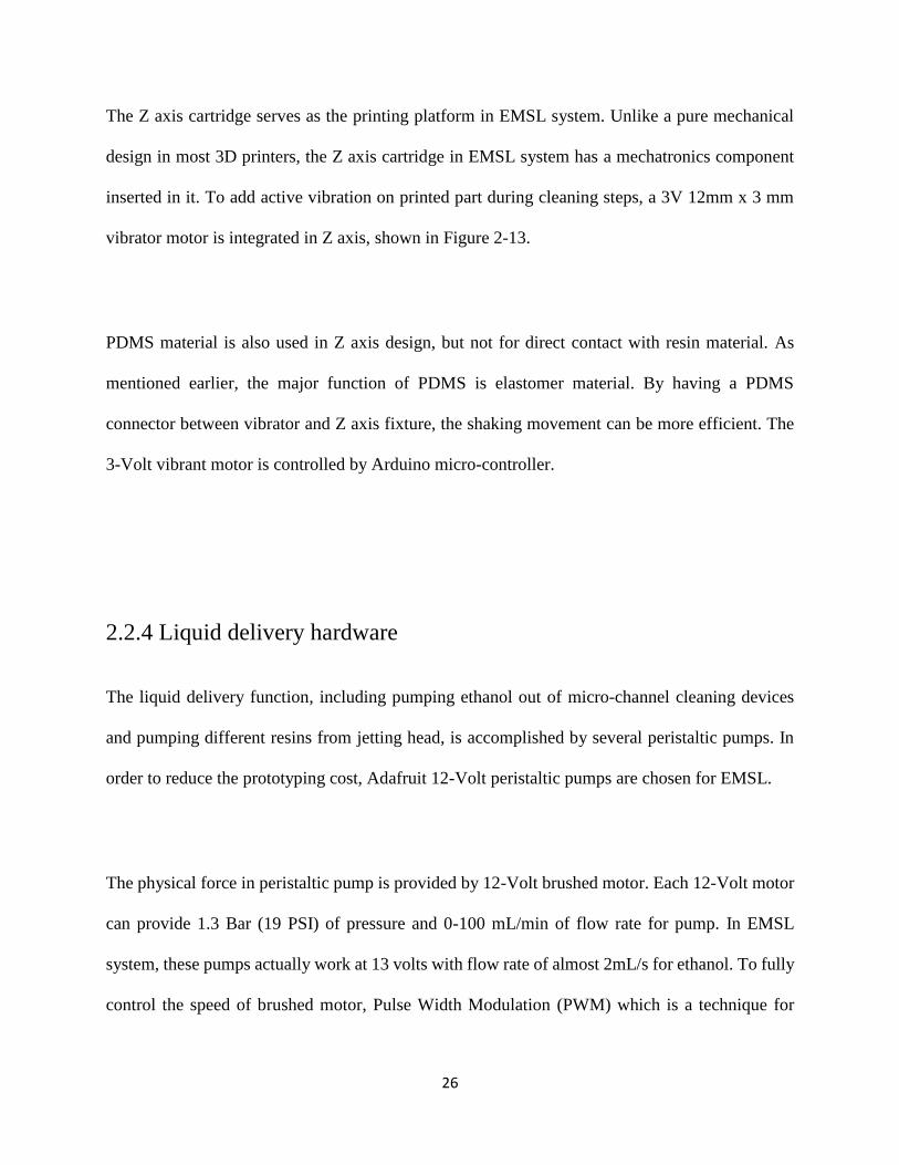
Figure 2-13. Assembled and exploded view of Z axis cartridge
26
The Z axis cartridge serves as the printing platform in EMSL system. Unlike a pure mechanical
design in most 3D printers, the Z axis cartridge in EMSL system has a mechatronics component
inserted in it. To add active vibration on printed part during cleaning steps, a 3V 12mm x 3 mm
vibrator motor is integrated in Z axis, shown in Figure 2-13.
PDMS material is also used in Z axis design, but not for direct contact with resin material. As
mentioned earlier, the major function of PDMS is elastomer material. By having a PDMS
connector between vibrator and Z axis fixture, the shaking movement can be more efficient. The
3-Volt vibrant motor is controlled by Arduino micro-controller.
2.2.4 Liquid delivery hardware
The liquid delivery function, including pumping ethanol out of micro-channel cleaning devices
and pumping different resins from jetting head, is accomplished by several peristaltic pumps. In
order to reduce the prototyping cost, Adafruit 12-Volt peristaltic pumps are chosen for EMSL.
The physical force in peristaltic pump is provided by 12-Volt brushed motor. Each 12-Volt motor
can provide 1.3 Bar (19 PSI) of pressure and 0-100 mL/min of flow rate for pump. In EMSL
system, these pumps actually work at 13 volts with flow rate of almost 2mL/s for ethanol. To fully
control the speed of brushed motor, Pulse Width Modulation (PWM) which is a technique for

27
getting analog results by digital methods, is used. The PWM signal is produced by Arduino and
Adafruit motor shield modules.
Table 2-1. Pump arrangement and operational details
Sequence No. Inlet Outlet Running speed Run time/cycle Delivery volume/cycle
1 Clean Ethanol X axis channel 160/255 5s 7.5mL
2 Clean Ethanol X axis channel 160/255 5s 7.5mL
3 Clean Ethanol Y axis channel 200/255 2s 3.2mL
4 Clean Ethanol Y axis channel 200/255 2s 3.2mL
5 Material A Nozzle A 150/255 5s 1.5mL
6 Material B Nozzle B 255/255 5s 1.5mL
There are 6 peristaltic pumps in total in EMSL system, shown in Table 2-1. In system operation
sequence: at first, pump 3 and 4 jet clean ethanol onto waste resin sitting on X axis PDMS window
and lower its viscosity for easy removal; then after manufactured part moving into X axis washing
tank, pump 1 and 2 jet clean ethanol and wash out remaining resin on part; finally, new material
is applied on building platform through pump 5 or pump 6.

28
2.3 Optical Design layout
The optical configuration of the EMSL system is depicted in Figure 2-14.
Figure 2-14. Optical design layout and major components
The optical light path consists of a pair of focusing lens, a pellicle beam splitter and a kinematic
beam turning cage. The tube lens couple, treated with anti-reflective coating to increase UV
transmission rate, adjusts focal length of real image. The pellicle beam splitter directs light into a
CCD camera, which is used to check system focus and to monitor the build process. The 45-degree
kinematic beam turning cage directs real image onto focal plane, which is orthogonal to optical
light path axis.

29
The lithography light source is a 405nm LED light engine. In the light engine, a series of fly’s eyes
and diffusers are used to condition the light intensity distribution. The light intensity, or
radiometric power, measured at the liquid monomer surface can range from 1mW to 400mW.
A DLP 5500 DMD display chip (Digital Micro-Mirror Device, TEXAS INSTRUMENTS Inc.) is
used as the digital mask in the EMSL system. This image forming chip is integrated within light
engine to reduce the prototyping difficulty of EMSL system design. The DMD mask has resolution
of 1024x768 in pixels over a 11.059mm by 8.294mm area. DLi CEL Control Software is connected
to light engine to control the display properties, including light intensity and projection size. UV
regulation optics adjust the display pixel size by a factor of 1:2, making the final image resolution
19.5 micron/pixel at the projection focal plane.
2.4 Software Design layout
2.4.1 System operating logic
Figure 2-15 shows the flowchart of the EMSL multi-material building process.
The first step of all printing operation is STL geometry design. Since EMSL print models with
multiple material, the geometry and boundary of each material should be defined. The author
designs each material geometry STL file in Solidworks and then assembles models in Autodesk
netfabb. Different material blocks are assembled in netfabb. Note that the parts should be placed
in the right place of the complete model, so that netfabb slices models in the designed height. After

30
the sliced bmp files are generated, a Matlab code rearranges all bmp file in a specially designed
sequence.
To increase the use efficiency of resin material, the material switchover procedure will be
conducted in every two layers rather than in every single layer. Same as material transition
procedure, the cleaning procedure is also performed every two layer [9]. To achieve this special
process, the EMSL system arrange the manufacturing sequence of various material (material A
and material B, for example) as: A𝑖 − B𝑖 − 𝐵𝑖+1 − 𝐴𝑖+1 rather than the intuitive A𝑖 − B𝑖 − 𝐴𝑖+1 −
𝐵𝑖+1 sequence. Using this method, less resin switchover time, less cleaning steps and less material
consumption are required.
Figure 2-15. Flowchart of EMSL building process

31
2.4.2 Arduino, LabVIEW and Smart Motor Interface
Since multiple hardware, such Moog Smart Motor, 12V peristaltic pumps, 3-Volt vibrant motor
and 12-Volt fan are operating under the same system, the operating software is actually built by
three piece of code: LabVIEW, SmartMotor SMI and Arduino.
The User Interface is written in LabVIEW. As we have discussed about STL slicing and bmp
image rearranging steps above, the processed bmp folder will be linked to LabVIEW. A txt file
describing layer exposure time and system motion programming is written and also linked into
LabVIEW. In LabVIEW front panel shown in Figure 2-16, users can monitor the model
completion percentage and layer completion percentage.
Figure 2-16. EMSL user interface in LabVIEW

32
Figure 2-17. EMSL software logic chart
In the control panel of LabVIEW code, MOOG Smart Motor micro controller and Arduino board
are communicating to LabVIEW at the same time by serial port. The software logic chart is shown
in Figure 2-17. The X, Y, Z linear actuator motion code is downloaded into Moog Smart Motor
micro controller; the peristaltic pump and fan controlling code is downloaded into Arduino. These
two operating sub-systems are physically separate, but logically linked by LabVIEW VISA serial
communication ports.

33
Chapter 3
3.Photo-polymer resin
3.1 Tunable Young’s modulus material
Researches on photo-polymer resin have been conducted for the development of technical material
with similar mechanical property like rubber, hard plastic etc. However, in order to demonstrate
the tunable negative Poisson’ ratio of honeycomb re-entrant structure, the author needs particular
resin with adjustable material properties (mainly Young’s Modulus). Although such photopolymer
products, with various Young’s Modulus from low to high, are available on market, for example
Somos 7000-9000 series covering Young’s modulus from 200-2000Mpa, the author still needs
more flexibility to tune the Young’s modulus within a single type of material.
FlexSL, developed by Arthur and Hermann [13], is a photopolymer formulation with excellent
Young’s Modulus tunability from 50-1000Mpa, crossing three orders of magnitude. To realize
more advanced AM applications such as novel silica-carbide, ceramic powder printing, FlexSL
class is also compatible enough to mix with multiple material groups.

34
3.2 Material composition
The excellent Young’s Modulus tunability of FlexSL photopolymer is enabled by two groups of
basic components: large molecular size oligomeric polyether(meth) acrylate monomers with very
elastic property and short molecular size cross-linking polyether(meth) acrylates monomers with
stiff property. The large molecular size monomer is labeled as material A and cross-linking
monomer is labeled as material B in this thesis. To make suitable FlexSL material for EMSL
manufacturing process, photo-initiator, UV blocker are specially chosen as well.
In EMSL programmable Poisson’s ratio application, the author chose main monomer components
as Bisphenol A ethoxylate dimethacrylate (simplified as component A) and Trimethylolpropane
triacrylate (simplified as component B). The UV blocker and photo-initiator are chosen as Sudan
I and Phenylbis (2,4,6-trimethyl-benzoyl) phosphine oxide respectively. The chemical
composition, weight percentage, of FlexSL 2-8 resin are listed in Table 3-1 below.
Table 3-1. Young’s modulus tunable material, FlexSL resin composition
FlexSL A B UV blocker Photo-initiator
8 79% 19.75% 0.25% 1%
7 69.125% 29.625%
6 59.25% 39.5%
5 49.375% 49.375%
4 39.5% 59.25%
3 29.625% 69.125%
2 19.75% 79%

35
3.3 Mechanical properties
To try out the optimized weight percentage of the photo-initiator and UV blocker, bridge test was
conducted as shown in Figure 3-1 below[4]. According to the test results, the author nailed down
0.25% Sudan I and 1% photo-initiator as the optimized weight percentage[14].
Figure 3-1. Bridge test on FlexSL4 material (a) Sudan I 0.1%, IRG 1%; (b)Sudan I 0.2%, IRG 1%; (c)Sudan I
0.25%, IRG 1%

36
To test the actual Young’s modulus value of FlexSL series resin made by author, the samples of
the final FlexSL formulations were then 3D printed into 1cm x 1cm x 1cm cubes using EMSL
system. The printed compression cubes were cleaned with ethanol and thoroughly dried. The
Young’s modulus of all compression samples were then measured with INSTRON 5944 precision
testing instrument according to ASTM E111-04: Standard Test Method for Young’s Modulus,
Tangent Modulus, and Chord Modulus. Measured Young’s modulus data of FlexSL4 – FlexSL8
and formlabs flexible resin are listed in Table 3-2 below.
Table 3-2. Measured Young’s modulus of FlexSL series material
Material Young’s Modulus(MPa)
FlexSL 8 33.0
FlexSL 7 54.5
FlexSL 6 86.0
FlexSL 5 152.5
FlexSL 4 200.0
formlabs flexible 10.0
From the results above, the FlexSL photopolymer resin made for EMSL system can vary the
Young’s Modulus from 33Mpa to 200Mpa. With the addition of formlabs flexible resin, which has
Young’s Modulus of 10Mpa, the printing material prepared for EMSL system can cross two orders
of magnitude in regard to the E value.

37
Chapter 4
4.Lattice design
4.1 NPR Structure
In contrast to most ordinary materials such as aluminum, steel, ABS plastic, rubber or rock, auxetic
structures expand laterally upon vertical stretch [15]. According to the definition of Poisson’s ratio:
negative transverse strain value over axial strain value in force direction, the auxetic structures
possess negative Poisson’s ratio (NPR). The concept of auxetic structure is first presented by Lakes
for foam structure research, and negative Poisson’s ratio, around -1, is proved to have great
mechanical properties such as high compressibility, high toughness, low indentation. Due to these
novel properties, auxetic structures are potential in applications such as shock-dissipating material,
bio-compatible design, fluid filter and fastener structures. This chapter demonstrates novel designs
of multi-material auxetic structures to be applied using EMSL system.
4.2 Honeycomb re-entrant structure
Due to novel mechanical properties of NPR structures, various researches have been focused on
the geometrical design of 2D auxetic material such as Chiral honeycomb geometry, Voronoi
cellular structures and honeycomb re-entrant structures.

38
A 3D honeycomb reentrant structure, shown in Figure 4-1(a), was first analytically investigated
by Li Yang et al. Under the premise of square struts cross section, four primary geometry
parameters will determine a design of 3D honeycomb structure unit cell: the vertical strut height
H, the re-entrant struts length L, the re-entrant and vertical struts angle 𝜽, and the side length t of
the square cross section. Figure 4-1(b) illustrates the geometrical parameters for the 2D
honeycomb unit cell structure.
Figure 4-1. 3D honeycomb reentrant structures. (a) Single material 3D re-entrant honeycomb lattice (b)
Geometrical parameters for the 2D re-entrant honeycomb unit cell structure. (c) Multi-material 3D re-entrant
honeycomb unit cell
Assume the 2D re-entrant structure rotates 90 degrees on vertical axis and duplicate multiple times
with all vertical and re-entrant struts merged on connection, the 3D re-entrant structure is then
formed as Figure 4-1 (a) shows, defined by four geometrical parameters. Take a periodic part as
unit cell of 3D re-entrant structure, shown in Figure 4-1(c), it is imaginable the re-entrant
honeycomb unit cell presents negative value of Poisson’s ratio in all three global directions.

39
Analytical results of single material re-entrant honeycomb unit cell have demonstrated that the
absolute value of Poisson’s ratio can be adjusted by means of two major geometric parameters:
the height versus re-entrant ratio H/L and re-entrant vertical angle θ.
Aided by EMSL system, other design parameters associated with the re-entrant honeycomb, such
as material properties of the re-entrant struts and those for the vertical struts, are added into lattice
design. Through further analytical multi-material modeling using large deflection beam theory in
next chapter, it is proved that not only geometric parameters , H/L and θ, can adjust 𝑣 value;
material combination is also effective in tuning the NPR value of auxetic structure.
To be more specific, two material variables are associated with the configuration of multi-material
honeycomb re-entrant unit cell, young’s modulus of re-entrant struts 𝐸𝑟 and young’s modulus of
vertical struts 𝐸𝑣 . This geometry-material design suggests that the 3D honeycomb re-entrant
structure can be tailored for desired material properties to suit different application needs without
heavy dependents on geometry change alone.

40
4.3 Idealized re-entrant structure
To demonstrate the versatility of EMSL system, an idealized reentrant unit cell, shown in Figure
4-2, is also investigated.
Figure 4-2. 3D Idealized reentrant unit cell. (a) Multi-material 3D idealized re-entrant unit cells (b) Angular
parameters shown on diagonal cross section of unit cell
Four geometry variables are associated with the design of idealized re-entrant unit cell, where L
denotes cubic edge length of unit cell, d denotes thickness of round or square cross section of all
struts members, θ𝑓𝑐 denotes the re-entrant angle of face-centered struts members and θ𝑒𝑑𝑔 denotes
the re-entrant angle of edge bipartite strut members. Two additional material variables are
associated with the novel multi-material idealized re-entrant where E𝑓𝑐 denotes the young’s

41
modulus of face-centered strut members and E𝑒𝑑𝑔 denotes the young’s modulus of edge bipartite
strut members.
To adapt idealized re-entrant unit cell design readily suitable for Bottom-up additive
manufacturing process, all the top and bottom struts angle are reduced to zero, while the overall
variable quantity remains the same. The unit cell design and lattice design of tailored idealized re-
entrant structures are shown in Figure 4-3.
Figure 4-3. 3D tailored Idealized reentrant structure. (a) Multi-material 3D tailored idealized re-entrant unit cells
(b) Multi-material 3D tailored idealized re-entrant lattice

42
Chapter 5
5.Analytical solution of multi-material
honeycomb structure
5.1 Force and displacement analysis with respect to
geometry
Figure 5-1(a) shows bi-material 3D honeycomb re-entrant lattice. This periodic lattice can be
represented by its unit cell shown in Figure 5-1(b).
Figure 5-1. (a) Bi-material 3D honeycomb re-entrant lattice ;(b) Bi-material 3D honeycomb re-entrant unit cell

43
The unit cell is divided into two parts with different material respectively: material R for reentrant
struts shown in color gray and material V for vertical struts shown in color blue. In the printing
process designed for NPR application, the joints of two materials is overlapped for higher interface
connectivity. That means, the joint region consists of both material R and material V.
Several assumptions were made for the analysis of unit cell structure[16]:
(1) Unit cell locates in infinite field. There’re infinite number of unit cells in every direction
next to the target unit cell. This assumption helps to eliminate boundary effects.
(2) All joints were rigid. Since the actual joints are built by two materials, assuming the joint
to be rigid can greatly simplify the analysis.
(3) Deformation of entire unit cell is only contributed by: bending deformation of re-entrant
units and axial deformation of vertical units. The beam model is suitable for both re-entrant
and vertical struts.
(4) Any possible Poisson’s effect, such as shrinkage or expansion of struts due to applied stress
were ignored.
Since the target unit cell is located in an infinite filed, when the infinite lattice structure has load
condition of normal compression along vertical struts, the target unit cell should only have load
also along vertical struts direction. Assume a normal stress field on top surface of unit cell to be
compressional and have the value of σ. The loading condition of the target multi-material unit cell
is then shown in Figure 5-2(a). Note that every vertical strut on the top is shared by four adjacent
unit cells, four struts on the corner should only have one-fourth load compared to central strut. Due
to highly symmetry property of honey-comb structure, the 3D multi-material unit cell can be

44
further simplified into 2D units which are marked out by red dash line. The force decomposition
of 2D unit cell is shown in Figure 5-2(b).
Figure 5-2. (a) Unit cell loading condition; (b) Force decomposition of 2D unit cell; (c) Force decomposition of the
2D element [16]
From Figure 5-2(b), the vertical beams only have compression force load as assumed earlier, while
the re-entrant beams are subject to shear force.
The values of load P and load T on re-entrant struts relative to F can be obtained from force
equilibrium:
P =F
4sinθ (1)
T =F
4cos 𝜃 (2)

45
Since the deformation of re-entrant strut is symmetry, obvious according to the symmetry load
condition, the re-entrant strut can be further simplified to be a beam of L/2 length. This half strut
can be treated as a cantilever beam which is fixed on one end and free on the other end. The fixed
end is joint of re-entrant and vertical beam, and the free end is the mid-point of re-entrant beam.
Figure 5-2 (c) shows the half re-entrant beam in deformed state, S is the arc length direction of the
beam with fixed origin point A, u is the half strut axial direction before any load applied and v is
the coordinate perpendicular to original strut alignment. The φ is the deflection angle describing
the angle between original and deformed strut alignment.
The relationship between local coordinate system and the global coordinate system for re-entrant
struts can be obtained from Figure 5-2(c).
Δx𝑟 = 2(Δu sin 𝜃 + Δv cos 𝜃) (3)
Δz𝑟 = 4(−Δu cos 𝜃 + Δv sin 𝜃) (4)
The subscript r in equation (3) and (4) means re-entrant strut.
The compression displacement of vertical struts in z direction was written as:
Δz𝑣 =2𝐹𝐻
𝐸𝑣 𝑡2 (5)
The subscript v in the equation (5) means vertical strut.
The total displacement in x and z directions for the Figure 5-2(b) structure are then obtained:
Δx = Δx𝑟 (6)
Δz = Δz𝑟 + Δ𝑧𝑣 (7)

46
5.2 Calculation of re-entrant strut displacement 𝚫𝐮 and 𝚫𝐯
In this particular multi-material honeycomb re-entrant structure case, the reentrant beam can no
longer be treated as small deflection situation, large deflection cantilever beam model for
displacement derivation is therefore considered.
According to Figure 5-2(c) cantilever beam coordinate system, the moment–curvature relationship
can be obtained:
E𝑟𝐼𝑟𝑑𝜑
𝑑𝑠= 𝑀 (8)
M is the moment and 𝑑𝜑
𝑑𝑠 is the curvature along beam arc length. The subscript r means re-entrant
beam.
Differentiate the moment-curvature equation with respect to s, we obtain:
E𝑟𝐼𝑟𝑑2𝜑
𝑑𝑠2 =𝑑𝑀
𝑑𝑠 (9)
In the above equations, the bending moment M of given point s along arc length is:
M(s) = 𝑃(𝐿
2− Δ𝑢 − 𝑢) (10)
Since 𝐿
2 and Δ𝑢 are not variables. The moment M can be differentiated by s as:
𝑑𝑀
𝑑𝑠= −𝑃
𝑑𝑢
𝑑𝑠 (11)
Note that cosφ =𝑑𝑢
𝑑𝑠 and take equation (11) into equation (9), we have equation (12):
E𝑟𝐼𝑟𝑑2𝜑
𝑑𝑠2 + 𝑃𝑐𝑜𝑠𝜑 = 0 (12)

47
Multiply equation (12) with 𝑑𝜑
𝑑𝑠, we have equation (13):
E𝑟𝐼𝑟𝑑𝜑
𝑑𝑠
𝑑2𝜑
𝑑𝑠2 + 𝑃𝑐𝑜𝑠𝜑𝑑𝜑
𝑑𝑠= 0 (13)
Further manipulate equation (13) as:
𝑑
𝑑𝑠[
1
2𝐸𝑟𝐼𝑟 (
𝑑𝜑
𝑑𝑠)
2
+ 𝑃𝑠𝑖𝑛𝜑] = 0 (14)
Now integrate equation (14) from s to free end φ (L
2) = 𝜑𝐿
2
, we obtain:
(𝑑𝜑
𝑑𝑠)
2
=2𝑃
𝐸𝑟𝐼𝑟(𝑠𝑖𝑛𝜑𝐿
2
− 𝑠𝑖𝑛𝜑) (15)
For some special design in which the re-entrant struts are not that long and slender, the shear effect
should not be ignored as a part of deflection:
φ =𝑑𝑢
𝑑𝑠+ 𝛾 (16)
The shear strain γ for square cross sectional beam can be written as:
γ =6𝑃
5𝐺𝑣𝐴 (17)
G𝑣 is the material shear modulus of vertical strut and A is cross sectional area of beam.
By integrating equation (15), and also notice that, when s=0 the deflection angle φ(0) = 𝛾, we
now have a function of arc length s with respect to variable φ:
s(φ) = √𝐸𝑟𝐼𝑟
2𝑃∫
𝑑𝜑
√𝑠𝑖𝑛𝜑𝐿2
−sin 𝜑
𝜑
𝛾 (18)

48
At the free end of re-entrant beam, the arc length s of beam should be equal to L/2, and deflection
angle can be assumed to be known φ𝐿
2
:
L
2= √
𝐸𝑟𝐼𝑟
2𝑃∫
𝑑𝜑
√𝑠𝑖𝑛𝜑𝐿2
−sin 𝜑
𝜑𝐿2
𝛾 (19)
Now define two new variables κ and α as:
κ = √1+𝑠𝑖𝑛𝜑𝐿
2
2 (20)
sin 𝛼 = √1+sin 𝜑
1+sin 𝜑𝐿2
(21)
Equation (19) can be manipulated into an elliptic integral equation:
F(κ2) − F(α0, κ2): ∫1
√1−𝜅2 sin2 𝛼𝑑𝛼
𝜋
2𝛼0
=L
2 √
𝑃
𝐸𝑟𝐼𝑟 (22)
The equation (22) is an elliptic integral function [17], and sin 𝛼0 =√1+sin 𝛾
√1+sin 𝜑𝐿2
=1
𝜅√
1+sin 𝛾
2 . Note
that α0 is also a function of κ, so the equation (22) only has one independent variable κ. The κ
value is calculated numerically in Matlab. When κ is value is known, by calculating equation (20),
we have φ𝐿
2
.

49
cos φ =𝑑𝑢
𝑑𝑠 and sin 𝜑 =
𝑑𝑣
𝑑𝑠, substitute them into equation (15) then we obtain[18]:
du = cos 𝜑 𝑑𝑠 = √𝐸𝑟𝐼𝑟
2𝑃
cos 𝜑
√sin 𝜑𝐿2
−sin 𝜑𝑑𝜑 (23)
d𝑣 = sin 𝜑 𝑑𝑠 = √𝐸𝑟𝐼𝑟
2𝑃
sin 𝜑
√sin 𝜑𝐿2
−sin 𝜑𝑑𝜑 (24)
When φ𝐿
2
value is determined, integrate equation (23) and equation (24) from fix point γ to free
end φ𝐿
2
. The half re-entrant strut displacement Δv and Δu are obtained:
Δu =𝐿
2− √
𝐸𝑟𝐼𝑟
2𝑃∫
cos 𝜑
√sin 𝜑𝐿2
−sin 𝜑
𝜑𝐿2
𝛾𝑑𝜑 (25)
Δv = √𝐸𝑟𝐼𝑟
2𝑃∫
sin 𝜑
√sin 𝜑𝐿2
−sin 𝜑
𝜑𝐿2
𝛾𝑑𝜑 (26)
5.3 Poisson’s ratios in z direction under compressive stress
After Δu and Δv are obtained, the deflection of the 5-2 (b) structure along the global coordinate
Δz and Δx can be determined. The Poisson’s ratio of multi-material re-entrant unit cell 𝑣𝑧𝑥 can be
calculated as:
v𝑧𝑥 = −ε𝑥
𝜀𝑧= −
Δ𝑥𝐿 sin 𝜃
Δ𝑧2(𝐻 − 𝐿 cos 𝜃)
= −2(𝐻 − 𝐿 cos 𝜃)Δ𝑥
𝐿 sin 𝜃 Δ𝑧

50
5.4 FEA validation on analytical solution
As we’ve described the analytical solution of honeycomb re-entrant structure previously, four
assumptions and large deflection cantilever beam model for re-entrant struts is employed in the
derivation process. To test if this analytical solution is a suitable prediction to physical world, the
finite element analysis (FEA) simulation is conducted as a set of comparison.
With help of ABAQUS commercial FEA software, the author conducted FEA simulations
according to different boundary conditions. The four primary geometry parameters in honeycomb
re-entrant design are chosen to be: θ = 60, H/L/t = 6:3:1 for FEA simulations. The same geometry
parameters were also imported in analytical solution, then the FEA simulation results and
analytical solution were compared.
In the analytical derivation, the lattice size is assumed to be infinitely large, and a random unit cell
is considered as the deformation unit. The FEA jobs are also based on infinite field assumption
and unit cell deformation.
The simulation model of first FEA job is a half 3D unit cell based on infinite field assumption, as
shown in Figure 5.3(a). Due to the symmetrical deformation of 3D unit cell, to simplify the
modeling process, a half 3D unit cell is built. The boundary conditions of first FEA job are: 1) all
vertical struts only deform in vertical direction; 2) the alignment of vertical struts are always in Y
direction; 3) four bottom strut mid nodes are restricted in Y direction but can freely move on XZ

51
plane and the bottom central node is fixed as origin point; 4) five top strut mid nodes are assigned
to strain of 2% in Y axis individually. Beam element is chosen to mesh the model.
Figure 5-3. Finite Element analysis of unit cell under infinite field assumption (a) 2% strain assigned individually on
top nodes; (b) 2% strain assigned on coupled nodes;
Same as the first FEA job, the second FEA simulation is also based on a half unit cell model,
shown in Figure 5.3(b). The boundary conditions of second FEA job are almost same as the
boundary conditions of first FEA job except the last condition. For second FEA job, the five top
strut mid nodes are coupled in XZ plane, which means there is no relative movement between the
five nodes. The coupled nodes are then assigned to strain of 2% as an entirety. Beam element is
employed.
To compare the analytical solution with the FEA simulation results, a E1/E2 vs Poisson’s ratio
plot is generated by Matlab code, shown in Figure 5.4. The E1 means Young’s Modulus of re-
entrant struts, and E2 means Young’s modulus of vertical struts.

52
Figure 5-4. Analytical solution and finite element simulation comparison
In this plot, analytical results and FEA simulations are listed and we can have the following
conclusions:
1) The Poisson’s ratio in all predictions are always negative.
2) The tendencies of Poisson’s ratio change according to the E1/E2 change are also consistent
in all predictions.
3) The infinite unit cell assumption produces very close results in FEA simulation and
analytical solution, but not exactly the same.
From the above four conclusions, the analytical solution is proved to be valid and it will be used
to compare with the experimental data in the following section.

53
Chapter 6
6.Results and conclusion
6.1 Multi-material honeycomb re-entrant lattice
As discussed in chapter 4, the Poisson’s ratio of multi-material honeycomb reentrant structure is
tunable in method of changing 𝐸𝑟/𝐸𝑣 values. In order to prove the analytical simulation, the author
has chosen the following Young’s modulus couple shown in Table 6-1.
Table 6-1. Honeycomb reentrant samples composition
Sample No. Reentrant struts 𝐸𝑟 Vertical struts 𝐸𝑣 𝐸𝑟/𝐸𝑣
Flexible-FlexSL4 Flexible 10MPa FlexSL4 200MPa 0.05000
FlexSL4-Flexible FlexSL4 200MPa Flexible 10MPa 20.0000
Flexible-FlexSL5 Flexible 10MPa FlexSL5 152.2MPa 0.06557
FlexSL5-Flexible FlexSL5 152.2MPa Flexible 10MPa 15.2500
Flexible-FlexSL6 Flexible 10MPa FlexSL6 86MPa 0.11628
FlexSL6-Flexible FlexSL6 86MPa Flexible 10MPa 8.60000
Flexible-FlexSL7 Flexible 10MPa FlexSL7 54.5MPa 0.18349
FlexSL7-Flexible FlexSL7 54.5MPa Flexible 10MPa 5.45000
Flexible-FlexSL8 Flexible 10MPa FlexSL8 30MPa 0.30303
FlexSL8-Flexible FlexSL8 30MPa Flexible 10MPa 3.30000
There are four geometrical design parameters for the multi-material honeycomb re-entrant unit cell
structure: vertical strut height H, re-entrant struts length L, the re-entrant angle 𝜃, and the strut
cross section side length t. According to EMSL system’s manufacturing characteristic, these four
parameters are chosen to be: 𝜃 = 60°, H / L / t = 10:5:1.

54
Having these parameters, the re-entrant struts and vertical struts are designed in Solidworks and
then assembled into lattice in Netfabb. Note that the entire lattice is divided into two material sets,
so the reentrant part and vertical part should be two independent geometry files. The lattice size is
5x2x6 in unit cells, and Figure 6-1 below shows reentrant lattice part, vertical lattice part and entire
lattice respectively. In the reentrant lattice part, the author has also designed wall geometries for
the convenience of tensile test.
Figure 6-1. Honeycomb reentrant design for tensile test (a) reentrant lattice part; (b) vertical lattice part; (c) entire
lattice;
Figure 6-2 shows the size information of manufactured honeycomb reentrant lattice.
Figure 6-2. Size information of manufactured multi-material honeycomb reentrant lattice

55
6.2 Tensile test on multi-material honeycomb re-entrant
samples
To measure the actual Poisson’s ratio of multi-material samples, a tensile test is carefully designed.
First off, the multi-material lattices are made into dog-bone samples by sticking one connector on
each side of top and bottom wall geometry, shown in Figure 6-3. Connectors have the same cross-
section area as wall geometry has, and they are made from Autodesk clear resin by Ember 3D
printer.
Figure 6-3. multi-material honeycomb reentrant lattice dog bone sample for tensile test

56
An INSTRON 5994 machine with 1000N load cell is chosen to provide the z axis tensile extension
for multi-material samples at a constant strain rate 0f 0.001/s. At the same time, a Dino-Lite digital
microscope record video of lattice deformation and take photos when the z axis tensile extension
reach 1%,2%,3%... all the way to 25%. The output photo from Dino-Lite is 2560x2048 in pixel.
Test stops once the lattice fractured, and the tensile limit is recorded for every sample.
The Poisson’s ratio is calculated by image analysis software specially designed for AMML lab,
GUI shown in Figure 6-4. Four points are picked up, and they stand for displacement in +Z, -Z,
+X and –X directions respectively. The Poisson’s ratio of a sample at a particular z axis strain is
then calculated by a simple equation: (𝑍2
′−𝑍1′)/(𝑍2−𝑍1)
(𝑋2′−𝑋1
′)/(𝑋2−𝑋1), where superscript ’ stands for deformed state.
The experimental result is shown in Figure 6-5.
Figure 6-4. Method of Poisson’s ratio measurement

57
Figure 6-5. Poisson’s ratio of multi-material honeycomb reentrant lattice samples with respect to strain
6.3 Results and discussions
Based on theoretical equations illustrated in Chapter 5, and also according to the actual parameters
of multi-material samples: : 𝜃 = 60, H = 3590μm, L = 2271μm and t = 454μm, a Poisson’s ratio
vs 𝐸1/𝐸2 plot is generated from matlab code, as shown in Figure 6-6. In this plot, the continuous
blue line stands for theoretical solution of Poisson’s ratio with 𝐸1/𝐸2 as the independent variable;
the red dots are measured Poisson’s ratio of ten samples described in Table 6-1; the x axis is value
of 𝐸1/𝐸2 in logarithm scale, the y axis is Poisson’s ratio value. The notation 𝐸1 is the Young’s
Modulus of re-entrant strut material and 𝐸2 is the Young’s Modulus of vertical strut material.
The result of analytical simulation is shown as a blue continuous line, and the Poisson’s ratio of
multi-material honeycomb re-entrant structure is always negative. The absolute value of Poisson’s
ratio is monotonic increasing with increased 𝐸1/𝐸2 values. When the value of 𝐸1/𝐸2 is around 1,

58
the Poisson’s ratio changes rapidly with respect to Young’s modulus ratio. When the value of
𝐸1/𝐸2 is around 0 or bigger than 10, the Poisson’s ratio doesn’t change much with respect to
Young’s modulus ratio.
To compare the analytical solution result with measured Young’s Modulus values of EMSL
manufactured samples, the author then picked out Poisson’s ratios at 3% strain of all samples and
added them onto analytical results.
Figure 6-6. Poisson’s ratio comparison, analytical prediction vs tensile test results
A tendency is clear in the experimental result, by changing 𝐸𝑟/𝐸𝑣 value , the Poisson’s ratio of the
lattice geometry vary along the analytical simulation line. However, the difference between
analytical and experimental data is obvious, the standard deviation of 10 sets of data difference is
0.1044. To further analysis the experimental relative error with respect to analytical solution, upper
and lower limit values of Poisson’s ratio were chosen to determine the reasonable prediction region.
The upper limit of the region is Poisson’s ratio of 0, since the Poisson’s ratio of auxetic structure

59
will always be negative. The lower limit of the reasonable region is Poisson’s ratio of -0.78, which
is the minimal value from the analytical solution. To calculate the relative errors between
experimental data and analytical solution, the absolute difference of two sets of data is compared
with respect to width of reasonable prediction region. The relative error of 10 experimental data is
listed in Table 6-2, and the averaged relative error is 12.6%.
Table 6-2. Relative error of 10 experimental data
Data No. 1 2 3 4 5 6 7 8 9 10
Relative error 12.53% 14.01% 13.71% 17.13% 18.33% 2.56% 7.09% 11.73% 17.03% 11.88%
The major inaccuracy in the plot appear in the deviation between simulation line and individual
experimental points. The following reasons are concluded for the inaccuracy:
1 Analytical simulation is achieved by calculating a unit cell in an infinite field while
experimental results come from lattice with finite number of unit cells.
2 The boundary effects of experimental samples cannot be neglected because of fixed wall
geometry and finite unit cell number, but the analytical simulation have reduced the
boundary effect to the minimal.
3 The image analysis method can introduce some error if the sample is not facing toward
camera orthogonally.
6.4 Idealized re-entrant lattice sample

60
To show the versatility of EMSL system, the author also printed idealized re-entrant lattice,
described above, using advanced material. The sample of idealized re-entrant lattice is shown in
Figure 6-7 below.
The white struts are made from transparent resin with 15% ceramic power. The average size of
ceramic particle is around 100nm. With carefully designed printing process in EMSL, the
boundary between blue and ceramic resin is clear. It would not be difficult to implement other
advanced material, such as highly viscous or other nano-particle resin into EMSL system.
Figure 6-7. Idealized re-entrant lattice, (a) top view; (b) diagonal view
6.5 Limitations of EMSL system
The first limitation of EMSL system is about nano-particles in functional resin. As shown in Figure
6-7(b) above. Although out of focus, the base of lattice is contaminated, so that the contrast of blue
and white color is not perfectly clear. The white color comes from 100 nm size ceramic powder,
and the blue color comes from dye in Autodesk resin. Both dye and ceramic power are nano-

61
particles. This contamination problem can also be found in MIP-SL multi-material SLA system
created by Zhou etc. [9]. Although the author has implemented fresh ethanol washing steps in
EMSL system, the resin switchover is not perfect while resin contains nano-particles.
One possible solution to nano-particle contamination is changing the direction of ethanol flow in
EMSL system. As shown in Figure 6-8(a), in current EMSL system, the fresh ethanol washes
lattice from bottom to up. Since EMSL system is an inverted SLA system, the resin residuals stay
at the bottom at lattice before the cleaning step. If the ethanol flow from bottom of lattice, it will
first be contaminated by nano-particle and then spread these particles upon earlier printed lattice
part. That is the reason of contamination as shown in Figure 6-7(b). To avoid the secondary
pollution of used ehanol, an improved EMSL system can let ethanol flow from top to bottom as
shown in Figure 6-8(b). The support structure, in this case, should be long enough so that ethanol
can flow through lattice from top to bottom. The air flow direction in blow drying step can also
change to top-bottom.
-
Figure 6-8. One possible solution to nano-particle contamination, (a) Bottom-up ethanol flow direction; (b) Top-
bottom ethanol flow direction.

62
The second limitation of EMSL is system resolution. The feature size of honeycomb re-entrant test
sample is around 450 microns as shown in Figure 6-2. The optimal feature size of EMSL system
is actually a little below 100 microns. A multi-material octet lattice is shown in Figure 6-9, and
the feature size of vertical strut is 72 microns. The UV pattern pixel size on focal plane, as
introduced in Section 2.3, is 19.5 microns/pixel, which is one third of current EMSL feature size
limit. The EMSL system has already achieve the optimal resolution based on current optical
configuration. However, notice that in Figure 6-9(b), some vertical struts are distorted. Since
EMSL printing process involves ethanol washing and blow drying steps, these physical forces can
damage delicate small structures. To solve the tiny structure distortion problem and improve the
practical printing resolution of EMSL system, ethanol cleaning and blow drying need extra
optimization.
Figure 6-9. Optimal EMSL resolution demonstrated by multi-material octet lattice, (a) Feature size of vertical strut;
(b) Distortion of vertical struts.

63
6.6 Conclusion
The EMSL system designed and manufactured by author is a functional AM system. The multi-
material honeycomb re-entrant lattice shows a similar tunable Poisson’s ratio functionality as
expected from analytical simulation, which means different material are printed into a designed
geometry but still keep their distinctive material properties. Besides the limitations and possible
solutions described above, to make the EMSL system more reliable for general 3D printing
applications, multiple extra improvements should be added.
The major improvement to EMSL system would be to add accurate resin supply method. The
EMSL has already used individual tube to deliver material upon PDMS window, but the thickness
of resin layer is much more than enough. The unused resin is a waste to production cost and it also
increases the cleaning liquid consumption. Since accurate resin supply will only change the Y axis
material jet-head, it would not be difficult to implement.
Another improvement to the EMSL system would be to further integrate the mechatronics sub-
system to reduce the number of micro-controllers and communication cables. Since the control
software of EMSL is now comprised of Arduino, SMI and LabVIEW, there’s great difficulty for
new users to get familiar with the system. Once basic parts such as step motors and various sensors
are implemented, it will be possible to explore more applications from research and commercial
area for EMSL system.

64
References
[1] Bártolo, P. J., 2011, Stereolithography: materials, processes and applications, Springer Science &
Business Media.
[2] Zheng, X., Deotte, J., Alonso, M. P., Farquar, G. R., Weisgraber, T. H., Gemberling, S., Lee, H., Fang,
N., and Spadaccini, C. M., 2012, "Design and optimization of a light-emitting diode projection micro-
stereolithography three-dimensional manufacturing system," Review of Scientific Instruments, 83(12), p.
125001.
[3] Tumbleston, J. R., Shirvanyants, D., Ermoshkin, N., Janusziewicz, R., Johnson, A. R., Kelly, D., Chen,
K., Pinschmidt, R., Rolland, J. P., Ermoshkin, A., Samulski, E. T., and DeSimone, J. M., 2015, "Continuous
liquid interface production of 3D objects," Science, 347(6228), pp. 1349-1352.
[4] Jacobs, P. F., "Fundamentals of stereolithography," Proc. Proceedings of the Solid Freeform Fabrication
Symposium, pp. 196-211.
[5] Lee, M. P., Cooper, G. J., Hinkley, T., Gibson, G. M., Padgett, M. J., and Cronin, L., 2015,
"Development of a 3D printer using scanning projection stereolithography," Sci Rep, 5, p. 9875.
[6] Jafari, M. A., Han, W., Mohammadi, F., Safari, A., Danforth, S. C., and Langrana, N., 2000, "A novel
system for fused deposition of advanced multiple ceramics," Rapid Prototyping Journal, 6(3), pp. 161-175.
[7] Khalil, S., Nam, J., and Sun, W., 2005, "Multi‐nozzle deposition for construction of 3D biopolymer
tissue scaffolds," Rapid Prototyping Journal, 11(1), pp. 9-17.
[8] Sugavaneswaran, M., and Arumaikkannu, G., 2014, "Modelling for randomly oriented multi material
additive manufacturing component and its fabrication," Materials & Design (1980-2015), 54, pp. 779-785.
[9] Zhou, C., Chen, Y., Yang, Z., and Khoshnevis, B., 2013, "Digital material fabrication using mask-
image-projection-based stereolithography," Rapid Prototyping Journal, 19(3), pp. 153-165.
[10] Choi, J. W., Kim, H. C., and Wicker, R., 2011, "Multi-material stereolithography," J Mater Process
Tech, 211(3), pp. 318-328.
[11] Dendukuri, D., Panda, P., Haghgooie, R., Kim, J. M., Hatton, T. A., and Doyle, P. S., 2008, "Modeling
of oxygen-inhibited free radical photopolymerization in a PDMS microfluidic device," Macromolecules,
41(22), pp. 8547-8556.
[12] Jang, J. H., Dendukuri, D., Hatton, T. A., Thomas, E. L., and Doyle, P. S., 2007, "A route to three-
dimensional structures in a microfluidic device: stop-flow interference lithography," Angew Chem Int Ed
Engl, 46(47), pp. 9027-9031.
[13] Bens, A., Seitz, H., Bermes, G., Emons, M., Pansky, A., Roitzheim, B., Tobiasch, E., and Tille, C.,
2007, "Non‐toxic flexible photopolymers for medical stereolithography technology," Rapid Prototyping
Journal, 13(1), pp. 38-47.

65
[14] Choi, J. W., MacDonald, E., and Wicker, R., 2010, "Multi-material microstereolithography," Int J Adv
Manuf Tech, 49(5-8), pp. 543-551.
[15] Lakes, R., 1987, "Foam structures with a negative Poisson's ratio," Science, 235(4792), pp. 1038-1040.
[16] Yang, L., Harrysson, O., West, H., and Cormier, D., 2015, "Mechanical properties of 3D re-entrant
honeycomb auxetic structures realized via additive manufacturing," International Journal of Solids and
Structures, 69, pp. 475-490.
[17] Good, R., 2001, "Elliptic integrals, the forgotten functions," European Journal of Physics, 22(2), p.
119.
[18] Beléndez, T., Neipp, C., and Beléndez, A., 2002, "Large and small deflections of a cantilever beam,"
European Journal of Physics, 23(3), p. 371.


![MAGNETIC-FIELD-ASSISTED PROJECTION STEREOLITHOGRAPHY FOR ... · For example, Khalil et al. [14] presented a multi-nozzle deposition system to 3D print polymer ... are then converted](https://img.pdfslide.net/doc/110x75/5b91296c09d3f2e6728d8dee/magnetic-field-assisted-projection-stereolithography-for-for-example-khalil.jpg)