Embed Size (px)
Citation preview
HAL Id: hal-01295439https://hal.archives-ouvertes.fr/hal-01295439
Submitted on 31 Mar 2016
HAL is a multi-disciplinary open accessarchive for the deposit and dissemination of sci-entific research documents, whether they are pub-lished or not. The documents may come fromteaching and research institutions in France orabroad, or from public or private research centers.
L’archive ouverte pluridisciplinaire HAL, estdestinée au dépôt et à la diffusion de documentsscientifiques de niveau recherche, publiés ou non,émanant des établissements d’enseignement et derecherche français ou étrangers, des laboratoirespublics ou privés.
A multi-order probabilistic approach for InstantaneousAngular Speed tracking. debriefing of the CMMNO’14
diagnosis contestQuentin Leclere, Hugo André, Jérôme Antoni
To cite this version:Quentin Leclere, Hugo André, Jérôme Antoni. A multi-order probabilistic approach for InstantaneousAngular Speed tracking. debriefing of the CMMNO’14 diagnosis contest. Mechanical Systems andSignal Processing, Elsevier, 2016, 10.1016/j.ymssp.2016.02.053. hal-01295439
A multi-order probabilistic approach for
Instantaneous Angular Speed tracking
debriefing of the CMMNO’14 diagnosis
contest
Quentin Leclere a,∗ Hugo Andre b Jerome Antoni a
aLaboratoire Vibrations Acoustique, INSA Lyon, 25 bis avenue Jean CapelleF-69621 Villeurbanne Cedex, FRANCE
bMaia Eolis,Tour de LILLE (19 etage) Bd de Turin 59777 Lille, FRANCE
Abstract
The aim of this work is to propose a novel approach for the estimation of the Instan-taneous Angular Speed (IAS) of rotating machines from vibration measurements.This work is originated from the organisation, by the authors of this paper, of acontest during the conference CMMNO 2014, that was held in Lyon, december 2014.One purpose of the contest was to extract the IAS of a wind turbine from a gearboxaccelerometer signal. The analysis of contestant contributions led to the observationthat the main source of error in this exercise was the wrong association of one se-lected and tracked harmonic component with one mechanical periodic phenomenon,this association being assumed as an a priori hypothesis by all the methods usedby the contestants. The approach proposed in this work does not need this kindof a priori assumption. A majority (but not necessarily all) periodical mechanicalevents are considered from a preliminary analysis of the kinematics of the machine(harmonics of shaft rotation speeds, meshing frequencies ...). The IAS is then deter-mined from probability density functions that are constructed from instantaneousspectra of the signal. The efficiency and robustness of the proposed approach areillustrated in the frame of the CMMNO 2014 contest case.
Key words: Instantaneous Angular Speed, wind turbines, order tracking,demodulation, virtual tacho
∗ Corresponding author. Fax: 33.4.72.43.87.12. E-mail address:[email protected].
Preprint submitted to Elsevier 24 March 2016
Nomenclature
Ω: IAS (Instantaneous Angular Speed) (in Hz)ω: argument of the probability density function (pdf) of the IAS (in Hz)A(f): whitened instantaneous spectrum (dimensionless), depending on the fre-quency f (in Hz)Ωmin: minimum value of the a priori IAS uniform law (in Hz)Ωmax: maximum value of the a priori IAS uniform law (in Hz)Hi (i ∈ [1...n]): orders of the mechanism, with respect to the IAS (dimension-less)[Ω|Hi]: pdf of the IAS knowing Hi, function of ω (in Hz)[Ωj|Ωj+k]: pdf of the IAS at time j knowing the IAS at time j + k, functionof ω (in Hz)[Ωj]j+k: pdf of the IAS at time j obtained from [Ωj+k], function of ω (in Hz)γ: standard acceleration for IAS (smoothing parameter), in (Hz2)[Ωj]s: smoothed pdf of the IAS at time j, function of ω (in Hz)
1 Introduction
In many aspects, the Instantaneous Angular Speed (IAS) is to the Condi-tion Monitoring of rotating machines what the heartbeat signal is to medicine.Just as in medicine, the IAS provides vital information for diagnosis and itallows resynchronization of subsequent analyses.The importance of the IAS and of its measurement has been addressed in arecent special issue of MSSP [1,2] and in a review paper [3]. Its use for ordertracking is also discussed in the review paper [4].As indicated by the adjective instantaneous, the IAS is a measure of the rota-tion speed of a rotating component in a machine with an angular resolutionthat corresponds to at least one value per revolution. The IAS enters as anessential ingredient to several processing techniques dedicated to the analysisof machines operating under nonstationary regimes.It has been for long an essential quantity in rotor dynamics and in NVH appli-cations concerned with the testing of rotating machines in transient regimessuch as runups and shutdowns. In this context, the IAS makes possible thesynchronization of Fourier analysis on the shaft rotation – a practice knownas order (spectral) analysis – or the tracking of the evolution of the Fouriercoefficients as a function of speed - a practice known as order tracking [5–7].Early successes of order tracking are exemplified by the Vold-Kalman filter[8–14], a model-based approach well suited to slow-speed variations and highSNRs. It is traditionally accepted that order analysis and order tracking ap-ply to deterministic signals which exhibit (modulated) harmonic structures inthe order domain. It is only recently that these ideas have been extended tobroadband signals. A typical example is provided by the vibrations of bearings
2
under nonstationary regimes, where order analysis has been successfully ap-plied to the signal envelope or to time-frequency energy distributions [15–17].The IAS also turns out essential to resample machine signals in the angulardomain in all applications where synchronization to the machine kinematicsis essential to correctly identify and analyze transient events in the machinecycle [18–20].The advantage of synchronizing signals to the angular domain has been fullyhighlighted within the cyclostationary framework, where the notion of ma-chine cycle is central [21,22]. The cyclostationary framework happens to per-fectly model most signals produced by rotating machines operating understationary regimes. The latter condition has recently been extended to non-stationary regimes, thus generalizing the cyclostationary class of signals tothe cyclononstationary class. One important contribution of the cyclononsta-tionary framework is to extend the principles of order analysis to any type ofsignal, including both deterministic and random types. In that context, theIAS constitutes a fundamental variable for their description [23,24].The IAS is not only useful as a reference signal; just as the heartbeat signalin medicine, it may serve as a diagnostic quantity per se. This has been earlyrecognized for the diagnostic of electric motors and of internal combustion en-gines [25–27] for instance and, more recently and perhaps more surprisingly,for the diagnosis of rolling element bearings [28,29]. Research is also ongoingto use the IAS for the monitoring of machining processes [30], in which caseit directly reflects the cutting forces.The measurement of the IAS is ideally achieved by a tachymeter mounted onthe machine. There exists various technologies, such as angular accelerometersor coder-based devices. In turn, the signals are either directly sampled in theangular domain by using the tachymetric signal as an external clock to theADC or aposteriori resampled by using digital processing algorithms. The lat-ter strategy is sometimes referred to as computer order tracking. These aspectsare discussed in Refs. [31–35,5]. Technological aspects of the measurement ofthe IAS and associated errors are further investigated in Refs. [36–39,29,40–42].The provision of a tachymeter with sufficient resolution is not always possi-ble for technological or cost reasons. In these situations, endeavors have beenmade to recover the IAS from the machine signals (e.g. vibrations). This isa most difficult situation, yet of major interest since it does not require anyspecific instrumentation and potentially returns the exact IAS of interest (e.g.the IAS used for subsequent resampling of the machine signals). One of thefirst successful attempt towards this direction is probably the non-parametricapproach based on complex envelope demodulation proposed in Ref. [14] andfurther refined in Ref. [43]. It applies to low speed fluctuations characterizedby a narrow-band spectrum as compared to the carrier frequency. Follow-ing this impetus, several demodulation methods have been proposed duringthe last six years in order to extract the IAS from complex vibration signalsin more general scenarios [44,15,45,46]. Model-based (e.g. Kalman filter) ap-
3
proaches demonstrate good accuracy [47–49], yet a patent limitation is thatall harmonics have to be modeled – even those which are not of interest -so as to produce a Gaussian residual. An important body of literature hasalso addressed the problem by using tailored time-frequency decompositionsuch as the Gabor transform and wavelet transforms [50–55]. The variety ofapproaches that have been proposed so far reflects the inherent difficulty ofthe problem. One difficulty actually stems from the multi-component natureof the signals where different families of harmonics may coexist, each beingcharacterized by numerous components (several tens or hundreds of harmon-ics are commonplace in some applications). Another difficulty stems from theinteraction between the orders and the structural resonances of the machine.One last difficulty is to operate under low SNRs as is typically the case withvibration signals (the noise being understood as any component in the signalwhich is not of direct interest for the analysis). All these challenges jeopardizethe application of standard signal processing tools dedicated to instantaneousfrequency estimation [56–59] and ask for a specific approach.In the presence of multi-component signals, it is actually advantageous totrack all harmonics jointly instead of individually as is proposed by most ofthe methods of the state-of-the-art. Since more information is considered atonce, the estimation of the IAS is expected to gain in accuracy. At the sametime, a gain in robustness is also envisioned in scenarios where some of theharmonics happen to fade or cross with other families. It is specifically theobject of this paper to propose a multi-harmonic tracking method.The present work finds its origins in the organization, by its authors, of a con-test during the The fourth International Conference on Condition Monitoringof Machinery in Non-Stationary Operations (CMMN0 2014). Contestants wereasked to extract an IAS from the vibration signal of a wind turbine’s gearbox.The first section of this paper is dedicated to a debriefing of this contest. Theanalysis of contributions, also discussed in the first section, led the authors ofthe present work to propose an innovative approach for blind IAS estimation,based on a probabilistic formalism: this is the object of the second section.The third section illustrates the efficiency of the method, in the frame of theCMMNO’14 contest signals.
2 CMMNO 2014 diagnosis contest
The fourth International Conference on Condition Monitoring of Machineryin Non-Stationary Operations (CMMN0 2014) was held in Lyon (France) onthe 15th and 16th of December 2014. More than one hundred people attendedthis event, from university and industry, among which several internationallevel experts in the field of rotating machine monitoring. Several months beforethe event, a diagnosis contest was launched: a signal, as well as some kinematicdata were provided to participants. The aim of the contest was to estimate theIAS of the rotating machine, and to propose a diagnosis of potential faults.
4
The contestants had to send back the estimation of the instantaneous speed,as well as a diagnostic report, a few weeks before the start of the conference.23 people registered to the contest, but only 8 contributions from 7 differentcountries have been received in due form by the Organization Committee.The results were presented during the afternoon plenary session of the 16thof December, and the first prize was awarded to Bob Randall, Michael Coatsand Wade Smith (University of new south Wales, in Sidney). They providedthe best estimation of the IAS, as compared to a reference that was directlymeasured with an angle encoder. The next section briefly resumes the casestudy addressed during the contest.
2.1 The case study: a wind turbine gearbox signal
Though gearbox defects appear to be 50% less frequent than electric systemfaults, the main cause of overall wind turbine downtime is related to gearboxfaults, as is can be seen in Fig. 1 and according to WindStats database anal-ysis focused on more than 30000 wind turbines [60]. This fact simply showsthat these occurrences are longer to be dealt with. However, bearing or evengearbox replacement never exceeds a few days. Most of the time is actuallyspent to order new components, manufacture and bring them on site alongwith available technicians. In case cranes are needed, extra time must be spentpreparing the platform and bringing a crane on site, which can be as long asobtaining a spare bearing. Hence, improving condition monitoring system abil-ity to detect gearbox fault as soon as possible allows limiting turbine downtimeto the duration of the replacement itself.
Although vibration monitoring benefits from wide academic and industrialexperiences, most of the works are focused on time based methods. Indus-trial equipments are therefore mainly dedicated to time based observationsand these simple systems are widely used in the wind industry for economicalreasons. Inherently relying on unsteady operating conditions, wind turbinesnevertheless presents the particularity to produce strongly non stationary mea-surements. Rotating speed and operating torque are constantly fluctuating andthe use of angle domain observations seems unavoidable. This shows the neces-sity to propose an approach based on time based acquisition system to tacklenon stationary problems. In particular, this paper focuses on a new method toresample the signal in the angle domain without the use of complex hardwareor even a tachymeter.Common to any wind turbine gearbox vibration signal are 3 kinds of periodicphenomena:• Time dependent phenomena produced by subsystems such as the converter
chopper frequency, the electric gear pump to help lubricant flow throughthe system, the heat exchanger fan, the natural frequencies of the structure(tower, blades, gearbox housing ...)
• Angle dependent, or more precisely, kinematic-dependent phenomena pro-
5
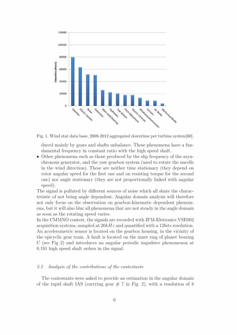
Fig. 1. Wind stat data base, 2008-2012 aggregated downtime per turbine system[60].
duced mainly by gears and shafts unbalance. These phenomena have a fun-damental frequency in constant ratio with the high speed shaft.
• Other phenomena such as those produced by the slip frequency of the asyn-chronous generator, and the yaw gearbox system (used to rotate the nacellein the wind direction). These are neither time stationary (they depend onrotor angular speed for the first one and on resisting torque for the secondone) nor angle stationary (they are not proportionally linked with angularspeed).
The signal is polluted by different sources of noise which all share the charac-teristic of not being angle dependent. Angular domain analysis will thereforenot only focus on the observation on gearbox-kinematic dependent phenom-ena, but it will also blur all phenomena that are not steady in the angle domainas soon as the rotating speed varies.In the CMMNO contest, the signals are recorded with IFM-Eletronics VSE002acquisition systems, sampled at 20kHz and quantified with a 12bits resolution.An accelerometric sensor is located on the gearbox housing, in the vicinity ofthe epicyclic gear train. A fault is located on the inner ring of planet bearingC (see Fig 2) and introduces an angular periodic impulsive phenomenon at0.191 high speed shaft orders in the signal.
2.2 Analysis of the contributions of the contestants
The contestants were asked to provide an estimation in the angular domainof the rapid shaft IAS (carrying gear # 7 in Fig. 2), with a resolution of 8
6
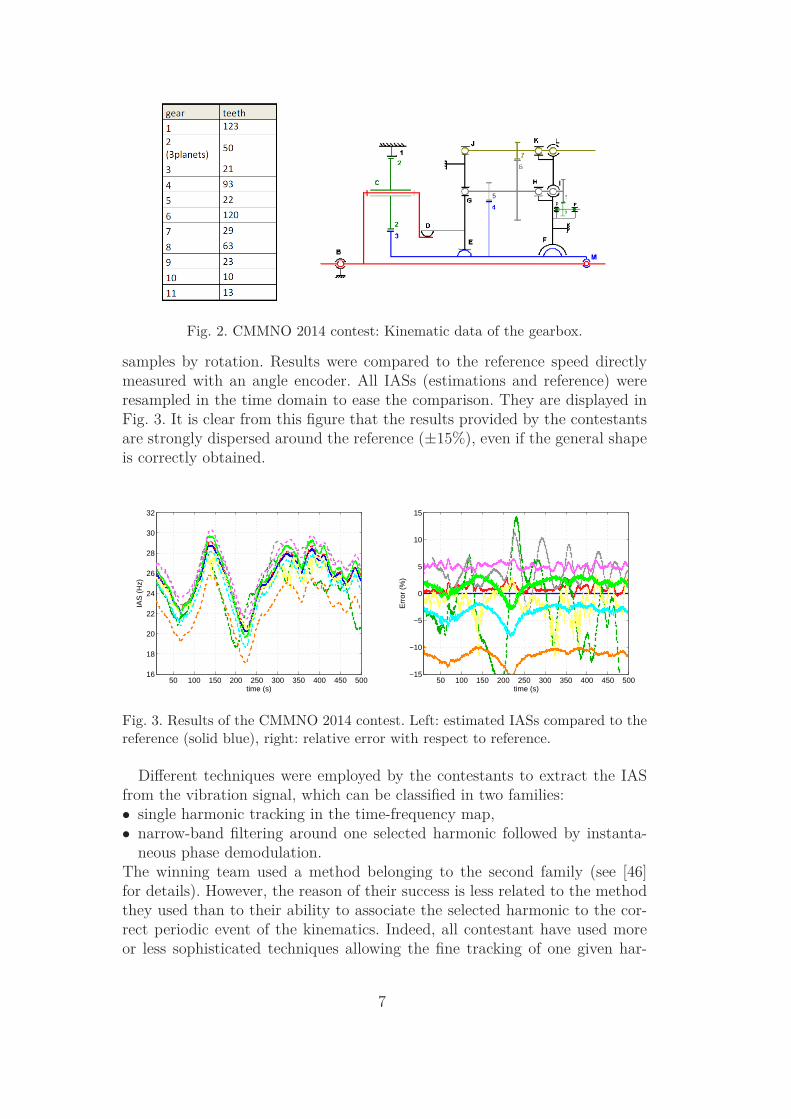
Fig. 2. CMMNO 2014 contest: Kinematic data of the gearbox.
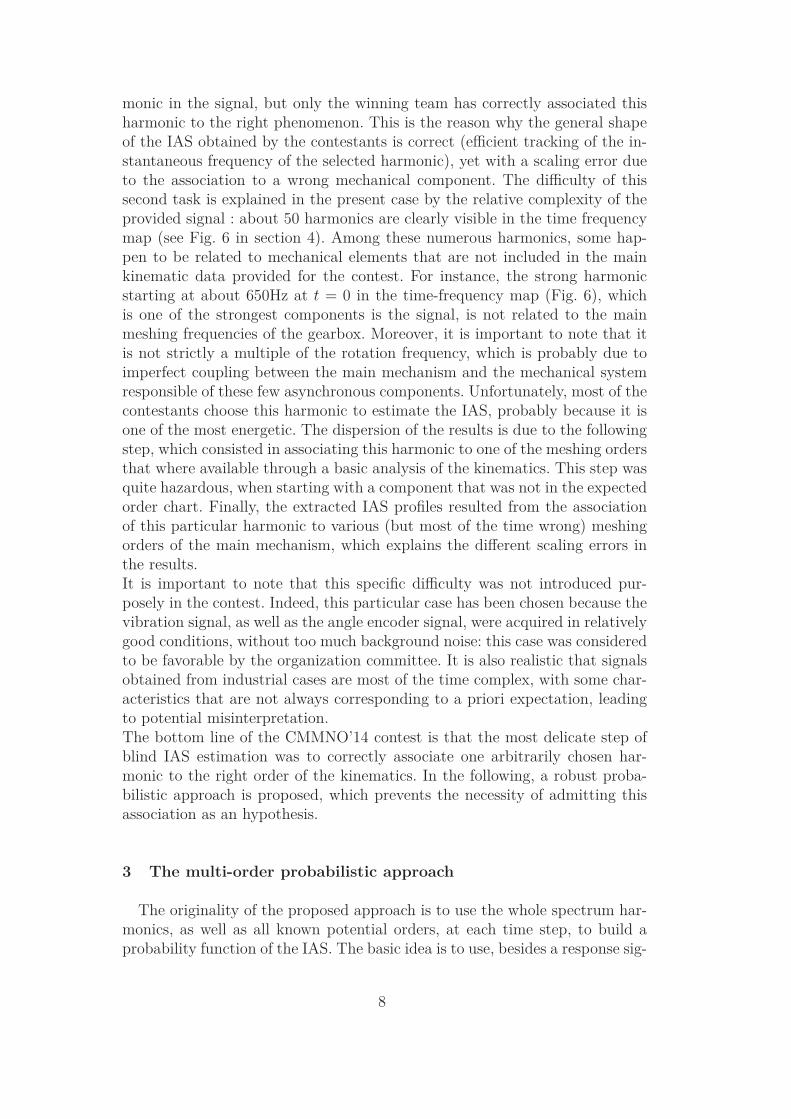
samples by rotation. Results were compared to the reference speed directlymeasured with an angle encoder. All IASs (estimations and reference) wereresampled in the time domain to ease the comparison. They are displayed inFig. 3. It is clear from this figure that the results provided by the contestantsare strongly dispersed around the reference (±15%), even if the general shapeis correctly obtained.
50 100 150 200 250 300 350 400 450 50016
18
20
22
24
26
28
30
32
time (s)
IAS
(H
z)
50 100 150 200 250 300 350 400 450 500−15
−10
−5
0
5
10
15
time (s)
Err
or (
%)
Fig. 3. Results of the CMMNO 2014 contest. Left: estimated IASs compared to thereference (solid blue), right: relative error with respect to reference.
Different techniques were employed by the contestants to extract the IASfrom the vibration signal, which can be classified in two families:• single harmonic tracking in the time-frequency map,• narrow-band filtering around one selected harmonic followed by instanta-
neous phase demodulation.The winning team used a method belonging to the second family (see [46]for details). However, the reason of their success is less related to the methodthey used than to their ability to associate the selected harmonic to the cor-rect periodic event of the kinematics. Indeed, all contestant have used moreor less sophisticated techniques allowing the fine tracking of one given har-
7
monic in the signal, but only the winning team has correctly associated thisharmonic to the right phenomenon. This is the reason why the general shapeof the IAS obtained by the contestants is correct (efficient tracking of the in-stantaneous frequency of the selected harmonic), yet with a scaling error dueto the association to a wrong mechanical component. The difficulty of thissecond task is explained in the present case by the relative complexity of theprovided signal : about 50 harmonics are clearly visible in the time frequencymap (see Fig. 6 in section 4). Among these numerous harmonics, some hap-pen to be related to mechanical elements that are not included in the mainkinematic data provided for the contest. For instance, the strong harmonicstarting at about 650Hz at t = 0 in the time-frequency map (Fig. 6), whichis one of the strongest components is the signal, is not related to the mainmeshing frequencies of the gearbox. Moreover, it is important to note that itis not strictly a multiple of the rotation frequency, which is probably due toimperfect coupling between the main mechanism and the mechanical systemresponsible of these few asynchronous components. Unfortunately, most of thecontestants choose this harmonic to estimate the IAS, probably because it isone of the most energetic. The dispersion of the results is due to the followingstep, which consisted in associating this harmonic to one of the meshing ordersthat where available through a basic analysis of the kinematics. This step wasquite hazardous, when starting with a component that was not in the expectedorder chart. Finally, the extracted IAS profiles resulted from the associationof this particular harmonic to various (but most of the time wrong) meshingorders of the main mechanism, which explains the different scaling errors inthe results.It is important to note that this specific difficulty was not introduced pur-posely in the contest. Indeed, this particular case has been chosen because thevibration signal, as well as the angle encoder signal, were acquired in relativelygood conditions, without too much background noise: this case was consideredto be favorable by the organization committee. It is also realistic that signalsobtained from industrial cases are most of the time complex, with some char-acteristics that are not always corresponding to a priori expectation, leadingto potential misinterpretation.The bottom line of the CMMNO’14 contest is that the most delicate step ofblind IAS estimation was to correctly associate one arbitrarily chosen har-monic to the right order of the kinematics. In the following, a robust proba-bilistic approach is proposed, which prevents the necessity of admitting thisassociation as an hypothesis.
3 The multi-order probabilistic approach
The originality of the proposed approach is to use the whole spectrum har-monics, as well as all known potential orders, at each time step, to build aprobability function of the IAS. The basic idea is to use, besides a response sig-
8
nal, all the information that is available about the kinematics of the machine.The knowledge (eventually partial) of the kinematics leads to a list of poten-tial orders that are supposed to strongly contribute to the vibration response,typically meshing frequencies and their harmonics. Each of these orders is usedto transform a short time instantaneous spectrum into a probability densityfunction of the fundamental rotation frequency. These pdfs are then combinedto obtain a global pdf, allowing the extraction of the most probable IAS.
3.1 Expected shape of the short time instantaneous response spectrum
The response spectrum results from the combination of the structural re-sponse and the excitation spectrum. In the case of strongly periodical exci-tations, the effects of the structure and of the excitation are generally wellseparated: the former governs the general envelop of the spectrum, while thelatter generates sharp peaks at integer multiples of the frequencies of periodicevents constituting the excitation. The response of the structure is withoutinterest considering the issue of identifying the IAS, and can actually be dis-turbing for the approach proposed in this work. A preliminary work thereforeconsists in suppressing, or at least attenuating the effect of the structure, byspectral whitening the signal. Several approaches can be used for spectralwhitening –one of which being described in Sec. 4– yet this preliminary step isconsidered as out of the scope of this paper, and will not be developed furtherin this theoretical part.
3.2 Considering the instantaneous response spectrum as a probability density
function of the IAS
Considering the knowledge of one given excitation order taken from thekinematics, noted Hi (in events by revolution of the main shaft), the instan-taneous spectrum of the response provides some information to build a pdfof the IAS Ω. Indeed, if the spectrum has a strong (resp. weak) amplitudeat the frequency f , then there is a high (resp. low) probability that the shaftfrequency is equal to f/Hi. Moreover, the range of the IAS has to be defined.This range is an a priori information that will be formalized by a prior pdf. Inthis work, this function will be considered as constant between a left boundΩmin and a right bound Ωmax. Finally, a conditional pdf can be defined asfollows (case 1)
[Ω|Hi] =1
ξi
A(Hiω) for Ωmin < ω < Ωmax (1)
[Ω|Hi] = 0 for ω < Ωmin | ω > Ωmax
9
where A(f) is a whitened version of the instantaneous spectrum of the responsesignal and ξi a normalization factor:
ξi =∫ Ωmax
Ωmin
A(Hiω)dω. (2)
The necessity of the whitening operation is here obvious: if part of the spec-trum is amplified by a strong modal behavior, it has to be compensated toavoid giving arbitrarily too much probability to the corresponding angularspeed range.
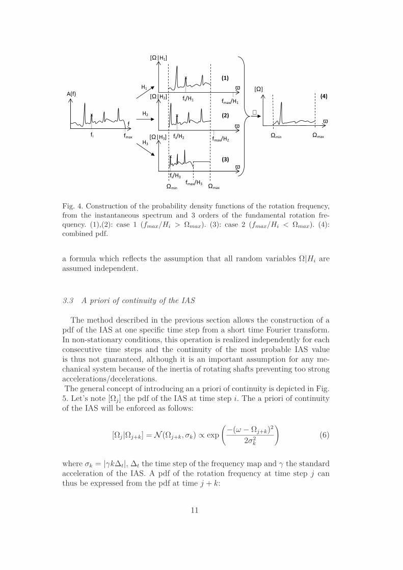
Equation (1) is fundamental in this work because it establishes how a simpleresponse spectrum, truncated between [Ωmin; Ωmax] and scaled by a factor Hi,is considered as a probability density function of the IAS, noted Ω, expressed inHz. Of course, the use of order Hi only will conduct to a strongly multi-modalpdf (as many modes than there are harmonic components in the spectrum),that cannot be used alone. Several orders will lead to several pdfs, that haveto be combined to obtain a meaningful result, i.e. an unimodal pdf (cf. Fig.4).The definition expressed by Eq. (1) cannot be used in all cases, for the wholerange of ω ∈ [Ωmin, Ωmax]. The spectrum of the response is indeed knownup to one given frequency noted fmax. Then, for values of ω above fmax/Hi,the spectrum of the response doesn’t bring any information. This situationappears if the considered harmonic Hi is greater than fmax/ω. In this case,the conditional pdf is made uniform above fmax/Hi (case 2):
[Ω|Hi] =1
ξi
A(Hiω) for Ωmin < ω < fmax/Hi (3)
[Ω|Hi] =1
(Ωmax − Ωmin)for fmax/Hi < ω < Ωmax
[Ω|Hi] = 0 for ω < Ωmin | ω > Ωmax
where A(f) is still the whitened instantaneous spectrum and ξi is such that
ξi =(Ωmax − Ωmin)
(fmax/Hi − Ωmin)
∫ fmax/Hi
Ωmin
A(Hiω)dω. (4)
An illustration of the construction of [Ω|Hi] from A(f) and Hi in the twoaforementioned cases is provided in Fig. 4. For orders H1 and H2, fmax/Hi ishigher than Ωmax, Eq. (1) can be used (case 1). For order H3, fmax/Hi is lowerthan Ωmax, Eq. (3) has to be used (case 2: a constant probability is consideredbetween fmax/Hi and Ωmax).Finally, the probability density functions are multiplied to combine the infor-
mation from all considered orders (Fig. 4, Subfig. (4)):
[Ω] ∝n∏
i=1
[Ω|Hi], (5)
10
ω
ω
Ω
ω
Ω
Ω
Ω Ω
ω
Ω
Ω Ω
⊗
Fig. 4. Construction of the probability density functions of the rotation frequency,from the instantaneous spectrum and 3 orders of the fundamental rotation fre-quency. (1),(2): case 1 (fmax/Hi > Ωmax). (3): case 2 (fmax/Hi < Ωmax). (4):combined pdf.
a formula which reflects the assumption that all random variables Ω|Hi areassumed independent.
3.3 A priori of continuity of the IAS
The method described in the previous section allows the construction of apdf of the IAS at one specific time step from a short time Fourier transform.In non-stationary conditions, this operation is realized independently for eachconsecutive time steps and the continuity of the most probable IAS valueis thus not guaranteed, although it is an important assumption for any me-chanical system because of the inertia of rotating shafts preventing too strongaccelerations/decelerations.The general concept of introducing an a priori of continuity is depicted in Fig.5. Let’s note [Ωj] the pdf of the IAS at time step i. The a priori of continuityof the IAS will be enforced as follows:
[Ωj|Ωj+k] = N (Ωj+k, σk) ∝ exp
(
−(ω − Ωj+k)2
2σ2k
)
(6)
where σk = |γk∆t|, ∆t the time step of the frequency map and γ the standardacceleration of the IAS. A pdf of the rotation frequency at time step j canthus be expressed from the pdf at time j + k:
11
Ω
δ
σ
σ
ω
Ω
ω
Ω
ω
Ω
ω
Ω
⊗
ω
Ω
ω
Ω
ω
Ω
Ω σ
ω σ
ω
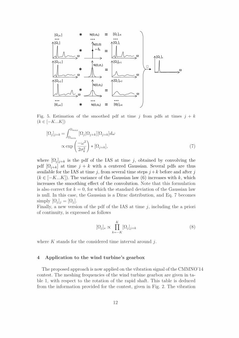
Fig. 5. Estimation of the smoothed pdf at time j from pdfs at times j + k(k ∈ [−K...K])
[Ωj]j+k =∫ Ωmax
Ωmin
[Ωj|Ωj+k][Ωj+k]dω
∝ exp
(
−ω2
2σ2k
)
∗ [Ωj+k], (7)
where [Ωj]j+k is the pdf of the IAS at time j, obtained by convolving thepdf [Ωj+k] at time j + k with a centered Gaussian. Several pdfs are thusavailable for the IAS at time j, from several time steps j +k before and after j(k ∈ [−K...K]). The variance of the Gaussian law (6) increases with k, whichincreases the smoothing effect of the convolution. Note that this formulationis also correct for k = 0, for which the standard deviation of the Gaussian lawis null. In this case, the Gaussian is a Dirac distribution, and Eq. 7 becomessimply [Ωj]j = [Ωj].Finally, a new version of the pdf of the IAS at time j, including the a prioriof continuity, is expressed as follows
[Ωj]s ∝K∏
k=−K
[Ωj]j+k (8)
where K stands for the considered time interval around j.
4 Application to the wind turbine’s gearbox
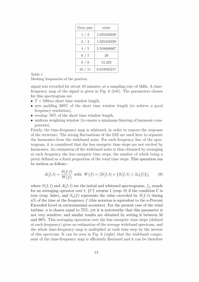
The proposed approach is now applied on the vibration signal of the CMMNO’14contest. The meshing frequencies of the wind turbine gearbox are given in ta-ble 1, with respect to the rotation of the rapid shaft. This table is deducedfrom the information provided for the contest, given in Fig. 2. The vibration
12
Gear pair order
1 / 2 1.025459229
2 / 3 1.025459229
4 / 5 5.316666667
6 / 7 29
8 / 9 15.225
10 / 11 6.619565217
Table 1Meshing frequencies of the gearbox.
signal was recorded for about 10 minutes, at a sampling rate of 5kHz. A time-frequency map of the signal is given in Fig. 6 (left). The parameters chosenfor this spectrogram are• T = 500ms short time window length,• zero padding 300% of the short time window length (to achieve a good
frequency resolution),• overlap: 50% of the short time window length,• uniform weighting window (to ensure a minimum blurring of harmonic com-
ponents).Firstly, the time-frequency map is whitened, in order to remove the responseof the structure. The strong fluctuations of the IAS are used here to separatethe harmonics from the wideband noise. For each frequency line of the spec-trogram, it is considered that the less energetic time steps are not excited byharmonics. An estimation of the wideband noise is thus obtained by averagingat each frequency the less energetic time steps, the number of which being apriori defined as a fixed proportion of the total time steps. This operation canbe written as follows :
A(f, t) =S(f, t)
W (f)with W (f) = 〈S(f, t) × S(f, t) < Sn(f)〉t (9)
where S(f, t) and A(f, t) are the initial and whitened spectrograms, 〈〉t standsfor an averaging operator over t, C returns 1 (resp. 0) if the condition C istrue (resp. false), and Sn(f) represents the value exceeded by S(f, t) duringn% of the time at the frequency f (this notation is equivalent to the n-PercentExceeded Level in environmental acoustics). For the present case of the windturbine, n is chosen equal to 75%, yet it is noteworthy that this parameter isnot very sensitive, and similar results are obtained by setting it between 50and 90%. This averaging operation over the less energetic time steps (definedat each frequency) gives an estimation of the average wideband spectrum, andthe whole time-frequency map is multiplied at each time step by the inverseof this spectrum. It can be seen in Fig. 6 (right) that the wideband compo-nent of the time-frequency map is efficiently flattened and it can be therefore
13
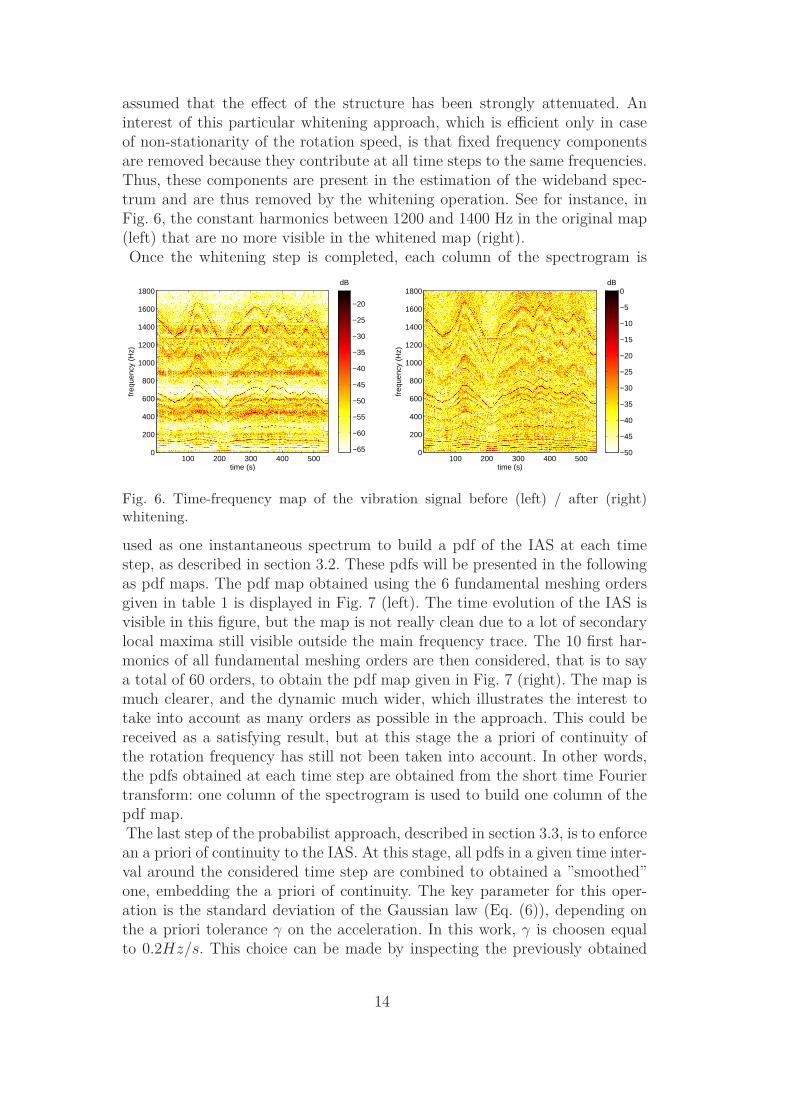
assumed that the effect of the structure has been strongly attenuated. Aninterest of this particular whitening approach, which is efficient only in caseof non-stationarity of the rotation speed, is that fixed frequency componentsare removed because they contribute at all time steps to the same frequencies.Thus, these components are present in the estimation of the wideband spec-trum and are thus removed by the whitening operation. See for instance, inFig. 6, the constant harmonics between 1200 and 1400 Hz in the original map(left) that are no more visible in the whitened map (right).Once the whitening step is completed, each column of the spectrogram is
time (s)
freq
uenc
y (H
z)
100 200 300 400 5000
200
400
600
800
1000
1200
1400
1600
1800dB
−65
−60
−55
−50
−45
−40
−35
−30
−25
−20
time (s)
freq
uenc
y (H
z)
100 200 300 400 5000
200
400
600
800
1000
1200
1400
1600
1800dB
−50
−45
−40
−35
−30
−25
−20
−15
−10
−5
0
Fig. 6. Time-frequency map of the vibration signal before (left) / after (right)whitening.
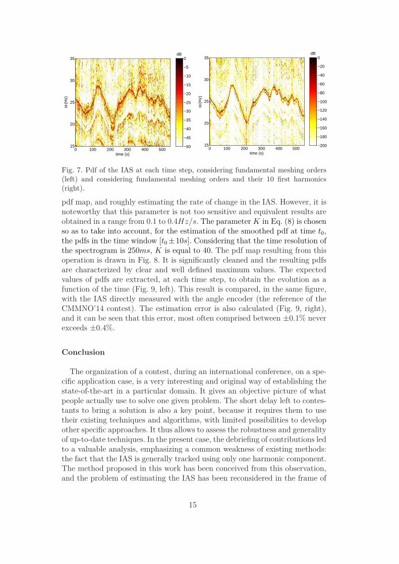
used as one instantaneous spectrum to build a pdf of the IAS at each timestep, as described in section 3.2. These pdfs will be presented in the followingas pdf maps. The pdf map obtained using the 6 fundamental meshing ordersgiven in table 1 is displayed in Fig. 7 (left). The time evolution of the IAS isvisible in this figure, but the map is not really clean due to a lot of secondarylocal maxima still visible outside the main frequency trace. The 10 first har-monics of all fundamental meshing orders are then considered, that is to saya total of 60 orders, to obtain the pdf map given in Fig. 7 (right). The map ismuch clearer, and the dynamic much wider, which illustrates the interest totake into account as many orders as possible in the approach. This could bereceived as a satisfying result, but at this stage the a priori of continuity ofthe rotation frequency has still not been taken into account. In other words,the pdfs obtained at each time step are obtained from the short time Fouriertransform: one column of the spectrogram is used to build one column of thepdf map.The last step of the probabilist approach, described in section 3.3, is to enforcean a priori of continuity to the IAS. At this stage, all pdfs in a given time inter-val around the considered time step are combined to obtained a ”smoothed”one, embedding the a priori of continuity. The key parameter for this oper-ation is the standard deviation of the Gaussian law (Eq. (6)), depending onthe a priori tolerance γ on the acceleration. In this work, γ is choosen equalto 0.2Hz/s. This choice can be made by inspecting the previously obtained
14
time (s)
ω (
Hz)
0 100 200 300 400 50015
20
25
30
35dB
−50
−45
−40
−35
−30
−25
−20
−15
−10
−5
0
time (s)
ω (H
z)
0 100 200 300 400 50015
20
25
30
35dB
−200
−180
−160
−140
−120
−100
−80
−60
−40
−20
0
Fig. 7. Pdf of the IAS at each time step, considering fundamental meshing orders(left) and considering fundamental meshing orders and their 10 first harmonics(right).
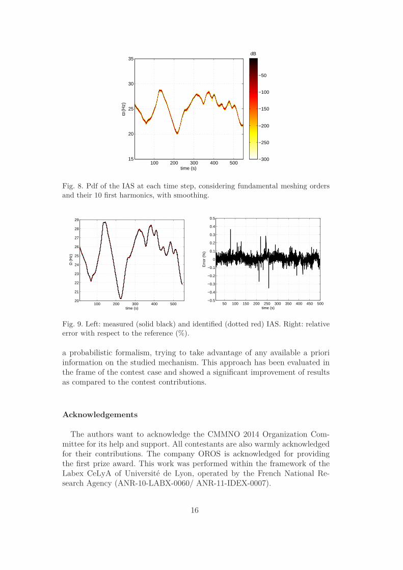
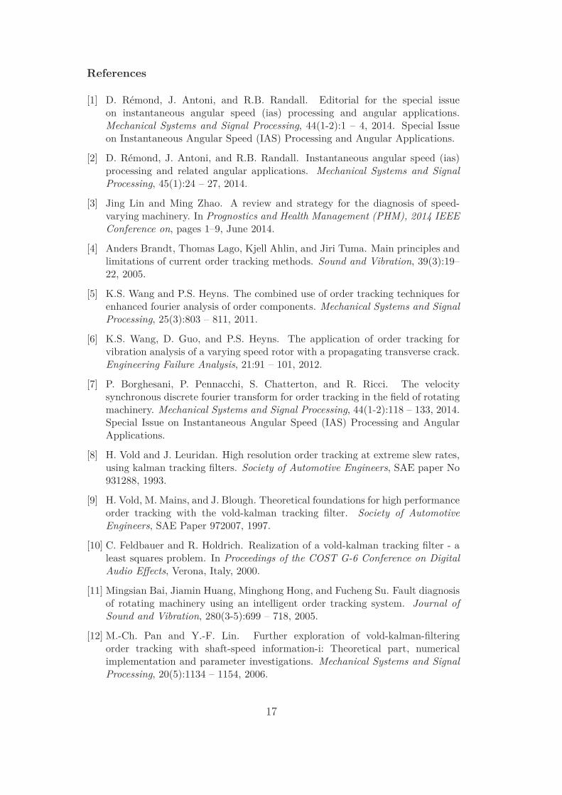
pdf map, and roughly estimating the rate of change in the IAS. However, it isnoteworthy that this parameter is not too sensitive and equivalent results areobtained in a range from 0.1 to 0.4Hz/s. The parameter K in Eq. (8) is chosenso as to take into account, for the estimation of the smoothed pdf at time t0,the pdfs in the time window [t0 ±10s]. Considering that the time resolution ofthe spectrogram is 250ms, K is equal to 40. The pdf map resulting from thisoperation is drawn in Fig. 8. It is significantly cleaned and the resulting pdfsare characterized by clear and well defined maximum values. The expectedvalues of pdfs are extracted, at each time step, to obtain the evolution as afunction of the time (Fig. 9, left). This result is compared, in the same figure,with the IAS directly measured with the angle encoder (the reference of theCMMNO’14 contest). The estimation error is also calculated (Fig. 9, right),and it can be seen that this error, most often comprised between ±0.1% neverexceeds ±0.4%.
Conclusion
The organization of a contest, during an international conference, on a spe-cific application case, is a very interesting and original way of establishing thestate-of-the-art in a particular domain. It gives an objective picture of whatpeople actually use to solve one given problem. The short delay left to contes-tants to bring a solution is also a key point, because it requires them to usetheir existing techniques and algorithms, with limited possibilities to developother specific approaches. It thus allows to assess the robustness and generalityof up-to-date techniques. In the present case, the debriefing of contributions ledto a valuable analysis, emphasizing a common weakness of existing methods:the fact that the IAS is generally tracked using only one harmonic component.The method proposed in this work has been conceived from this observation,and the problem of estimating the IAS has been reconsidered in the frame of
15
time (s)
ω (H
z)
100 200 300 400 50015
20
25
30
35dB
−300
−250
−200
−150
−100
−50
Fig. 8. Pdf of the IAS at each time step, considering fundamental meshing ordersand their 10 first harmonics, with smoothing.
100 200 300 400 50020
21
22
23
24
25
26
27
28
29
time (s)
Ω (
Hz)
50 100 150 200 250 300 350 400 450 500−0.5
−0.4
−0.3
−0.2
−0.1
0
0.1
0.2
0.3
0.4
0.5
time (s)
Err
or (
%)
Fig. 9. Left: measured (solid black) and identified (dotted red) IAS. Right: relativeerror with respect to the reference (%).
a probabilistic formalism, trying to take advantage of any available a prioriinformation on the studied mechanism. This approach has been evaluated inthe frame of the contest case and showed a significant improvement of resultsas compared to the contest contributions.
Acknowledgements
The authors want to acknowledge the CMMNO 2014 Organization Com-mittee for its help and support. All contestants are also warmly acknowledgedfor their contributions. The company OROS is acknowledged for providingthe first prize award. This work was performed within the framework of theLabex CeLyA of Universite de Lyon, operated by the French National Re-search Agency (ANR-10-LABX-0060/ ANR-11-IDEX-0007).
16
References
[1] D. Remond, J. Antoni, and R.B. Randall. Editorial for the special issueon instantaneous angular speed (ias) processing and angular applications.Mechanical Systems and Signal Processing, 44(1-2):1 – 4, 2014. Special Issueon Instantaneous Angular Speed (IAS) Processing and Angular Applications.
[2] D. Remond, J. Antoni, and R.B. Randall. Instantaneous angular speed (ias)processing and related angular applications. Mechanical Systems and SignalProcessing, 45(1):24 – 27, 2014.
[3] Jing Lin and Ming Zhao. A review and strategy for the diagnosis of speed-varying machinery. In Prognostics and Health Management (PHM), 2014 IEEEConference on, pages 1–9, June 2014.
[4] Anders Brandt, Thomas Lago, Kjell Ahlin, and Jiri Tuma. Main principles andlimitations of current order tracking methods. Sound and Vibration, 39(3):19–22, 2005.
[5] K.S. Wang and P.S. Heyns. The combined use of order tracking techniques forenhanced fourier analysis of order components. Mechanical Systems and SignalProcessing, 25(3):803 – 811, 2011.
[6] K.S. Wang, D. Guo, and P.S. Heyns. The application of order tracking forvibration analysis of a varying speed rotor with a propagating transverse crack.Engineering Failure Analysis, 21:91 – 101, 2012.
[7] P. Borghesani, P. Pennacchi, S. Chatterton, and R. Ricci. The velocitysynchronous discrete fourier transform for order tracking in the field of rotatingmachinery. Mechanical Systems and Signal Processing, 44(1-2):118 – 133, 2014.Special Issue on Instantaneous Angular Speed (IAS) Processing and AngularApplications.
[8] H. Vold and J. Leuridan. High resolution order tracking at extreme slew rates,using kalman tracking filters. Society of Automotive Engineers, SAE paper No931288, 1993.
[9] H. Vold, M. Mains, and J. Blough. Theoretical foundations for high performanceorder tracking with the vold-kalman tracking filter. Society of AutomotiveEngineers, SAE Paper 972007, 1997.
[10] C. Feldbauer and R. Holdrich. Realization of a vold-kalman tracking filter - aleast squares problem. In Proceedings of the COST G-6 Conference on DigitalAudio Effects, Verona, Italy, 2000.
[11] Mingsian Bai, Jiamin Huang, Minghong Hong, and Fucheng Su. Fault diagnosisof rotating machinery using an intelligent order tracking system. Journal ofSound and Vibration, 280(3-5):699 – 718, 2005.
[12] M.-Ch. Pan and Y.-F. Lin. Further exploration of vold-kalman-filteringorder tracking with shaft-speed information-i: Theoretical part, numericalimplementation and parameter investigations. Mechanical Systems and SignalProcessing, 20(5):1134 – 1154, 2006.
17
[13] Min-Chun Pan and Cheng-Xue Wu. Adaptive vold-kalman filtering ordertracking. Mechanical Systems and Signal Processing, 21(8):2957 – 2969, 2007.
[14] F. Bonnardot, M. El Badaoui, R.B. Randall, J. Daniere, and F. Guillet. Useof the acceleration signal of a gearbox in order to perform angular resampling(with limited speed fluctuation). Mechanical Systems and Signal Processing,19(4):766 – 785, 2005.
[15] Jacek Urbanek, Tomasz Barszcz, and Jerome Antoni. Time-frequency approachto extraction of selected second-order cyclostationary vibration components forvarying operational conditions. Measurement, 46(4):1454 – 1463, 2013.
[16] P. Borghesani, R. Ricci, S. Chatterton, and P. Pennacchi. A new procedurefor using envelope analysis for rolling element bearing diagnostics in variableoperating conditions. Mechanical Systems and Signal Processing, 38(1):23 – 35,2013. Condition monitoring of machines in non-stationary operations.
[17] Weidong Cheng, Robert X. Gao, Jinjiang Wang, Tianyang Wang, Weigang Wen,and Jianyong Li. Envelope deformation in computed order tracking and errorin order analysis. Mechanical Systems and Signal Processing, 48(1-2):92 – 102,2014.
[18] J. Antoni, J. Daniere, and F. Guillet. Effective vibration analysis of ic enginesusing cyclostationarity. part i-a methodology for condition monitoring. Journalof Sound and Vibration, 257(5):815 – 837, 2002.
[19] Luisa F. Villa, Anibal Renones, Jose R. Peran, and Luis J. de Miguel. Angularresampling for vibration analysis in wind turbines under non-linear speedfluctuation. Mechanical Systems and Signal Processing, 25(6):2157 – 2168, 2011.Interdisciplinary Aspects of Vehicle Dynamics.
[20] Marco Cocconcelli, Luca Bassi, Cristian Secchi, Cesare Fantuzzi, and RiccardoRubini. An algorithm to diagnose ball bearing faults in servomotors runningarbitrary motion profiles. Mechanical Systems and Signal Processing, 27:667 –682, 2012.
[21] J. Antoni, F. Bonnardot, A. Raad, and M. El Badaoui. Cyclostationarymodelling of rotating machine vibration signals. Mechanical Systems and SignalProcessing, 18(6):1285 – 1314, 2004.
[22] J. Antoni. Cyclostationarity by examples. Mechanical Systems and SignalProcessing, 23(4):987 – 1036, 2009.
[23] Dany Abboud, Jerome Antoni, Mario Eltabach, and Sophie Sieg-Zieba.Angletime cyclostationarity for the analysis of rolling element bearingvibrations. Measurement, 75:29 – 39, 2015.
[24] D. Abboud, J. Antoni, S. Sieg-Zieba, and M. Eltabach. Deterministic-randomseparation in nonstationary regime. Journal of Sound and Vibration, pages –,2015.
18
[25] Ahmed Yousef Ben Sasi, Fengshou Gu, Bradley Payne, and Andrew Ball.Instantaneous angular speed monitoring of electric motors. Journal of Qualityin Maintenance Engineering, 10(2):123–135, 2004.
[26] Jianguo Yang, Lijun Pu, Zhihua Wang, Yichen Zhou, and Xinping Yan. Faultdetection in a diesel engine by analysing the instantaneous angular speed.Mechanical Systems and Signal Processing, 15(3):549 – 564, 2001.
[27] M. Desbazeille, R.B. Randall, F. Guillet, M. El Badaoui, and C. Hoisnard.Model-based diagnosis of large diesel engines based on angular speed variationsof the crankshaft. Mechanical Systems and Signal Processing, 24(5):1529 – 1541,2010. Special Issue: Operational Modal Analysis.
[28] L. Renaudin, F. Bonnardot, O. Musy, J.B. Doray, and D. Remond. Naturalroller bearing fault detection by angular measurement of true instantaneousangular speed. Mechanical Systems and Signal Processing, 24(7):1998 – 2011,2010. Special Issue: ISMA 2010.
[29] Adeline Bourdon, Hugo Andre, and Didier Remond. Introducing angularlyperiodic disturbances in dynamic models of rotating systems under non-stationary conditions. Mechanical Systems and Signal Processing, 44(1-2):60– 71, 2014. Special Issue on Instantaneous Angular Speed (IAS) Processing andAngular Applications.
[30] M. Lamraoui, M. Thomas, M. El Badaoui, and F. Girardin. Indicatorsfor monitoring chatter in milling based on instantaneous angular speeds.Mechanical Systems and Signal Processing, 44(1-2):72 – 85, 2014. Special Issueon Instantaneous Angular Speed (IAS) Processing and Angular Applications.
[31] R. Potter. A new order tracking method for rotating machinery. Sound andVibration, 7:30–34, 1990.
[32] K.R. Fyfe and E.D.S. Munck. Analysis of computed order tracking. MechanicalSystems and Signal Processing, 11(2):187 – 205, 1997.
[33] K.m. Bossley, R.j. Mckendrick, C.j. Harris, and C. Mercer. Hybrid computedorder tracking. Mechanical Systems and Signal Processing, 13(4):627 – 641,1999.
[34] Yuhua Li, Fengshou Gu, Georgina Harris, Andrew Ball, Nick Bennett, and KenTravis. The measurement of instantaneous angular speed. Mechanical Systemsand Signal Processing, 19(4):786 – 805, 2005.
[35] P.N. Saavedra and C.G. Rodriguez. Accurate assessment of computed ordertracking. Shock and Vibration, 13:13–32, 2006.
[36] Fengshou Gu, Isa Yesilyurt, Yuhua Li, Georgina Harris, and Andrew Ball. Aninvestigation of the effects of measurement noise in the use of instantaneousangular speed for machine diagnosis. Mechanical Systems and Signal Processing,20(6):1444 – 1460, 2006. Special Issue: Laser Doppler Vibrometry.
19
[37] S.D. Yu and X. Zhang. A data processing method for determining instantaneousangular speed and acceleration of crankshaft in an aircraft engine-propellersystem using a magnetic encoder. Mechanical Systems and Signal Processing,24(4):1032 – 1048, 2010.
[38] K. Janssens, P. Van Vlierberghe, W. Claes, B. Peeters, T. Martens, andPh. D’Hondt. Zebra tape butt joint detection and correction algorithm forrotating shafts with torsional vibrations. In Proceedings of the ISMA 2010,International Conference on Modal Analysis Noise and Vibration Engineering,Leuven, Belgium, 2010.
[39] M. El Badaoui and F. Bonnardot. Impact of the non-uniform angular samplingon mechanical signals. Mechanical Systems and Signal Processing, 44(1-2):199– 210, 2014. Special Issue on Instantaneous Angular Speed (IAS) Processingand Angular Applications.
[40] Alessandro Rivola and Marco Troncossi. Zebra tape identification for theinstantaneous angular speed computation and angular resampling of motorbikevalve train measurements. Mechanical Systems and Signal Processing, 44(1-2):5– 13, 2014. Special Issue on Instantaneous Angular Speed (IAS) Processing andAngular Applications.
[41] H. Andre, F. Girardin, A. Bourdon, J. Antoni, and D. Remond. Precision ofthe IAS monitoring system based on the elapsed time method in the spectraldomain. Mechanical Systems and Signal Processing, 44(1-2):14 – 30, 2014.Special Issue on Instantaneous Angular Speed (IAS) Processing and AngularApplications.
[42] Q. Leclere, F. Girardin, and D. Remond. An analysis of instantaneous angularspeed measurement errors. In Proceedings of Surveillance 7, Chartres, France,2013.
[43] F. Combet and L. Gelman. An automated methodology for performing timesynchronous averaging of a gearbox signal without speed sensor. MechanicalSystems and Signal Processing, 21(6):2590 – 2606, 2007.
[44] R. Zimroz, J. Urbanek, T. Barszcz, W. Bartelmus, F. Millioz, and N. Martin.Measurement of instantaneous shaft speed by advanced vibration signalprocessing-application to wind turbine gearbox. Metrology and MeasurementSystems, 13:701–712, 2011.
[45] Ming Zhao, Jing Lin, Xiufeng Wang, Yaguo Lei, and Junyi Cao. A tacho-lessorder tracking technique for large speed variations. Mechanical Systems andSignal Processing, 40(1):76 – 90, 2013.
[46] Michael D. Coats and Robert B. Randall. Single and multi-stage phasedemodulation based order-tracking. Mechanical Systems and Signal Processing,44(1-2):86 – 117, 2014. Special Issue on Instantaneous Angular Speed (IAS)Processing and Angular Applications.
[47] Jean-Luc Dion, Cyrille Stephan, Gael Chevallier, and Hugo Festjens. Trackingand removing modulated sinusoidal components: A solution based on the
20
kurtosis and the extended kalman filter. Mechanical Systems and SignalProcessing, 38(2):428 – 439, 2013.
[48] Konstantinos Rodopoulos, Christos Yiakopoulos, and Ioannis Antoniadis. Aparametric approach for the estimation of the instantaneous speed of rotatingmachinery. Mechanical Systems and Signal Processing, 44(1-2):31 – 46, 2014.Special Issue on Instantaneous Angular Speed (IAS) Processing and AngularApplications.
[49] O. Cardona-Morales, L.D. Avendano, and G. Castellanos-Dominguez. Nonlinearmodel for condition monitoring of non-stationary vibration signals in shipdriveline application. Mechanical Systems and Signal Processing, 44(1-2):134 –148, 2014. Special Issue on Instantaneous Angular Speed (IAS) Processing andAngular Applications.
[50] Konstantinos C. Gryllias and Ioannis A. Antoniadis. Estimation of theinstantaneous rotation speed using complex shifted morlet wavelets. MechanicalSystems and Signal Processing, 38(1):78 – 95, 2013. Condition monitoring ofmachines in non-stationary operations.
[51] Hui Shao, Wei Jin, and S. Qian. Order tracking by discrete gabor expansion.Instrumentation and Measurement, IEEE Transactions on, 52(3):754–761, June2003.
[52] Junsheng Cheng, Yu Yang, and Dejie Yu. Application of the improvedgeneralized demodulation time-frequency analysis method to multi-componentsignal decomposition. Signal Processing, 89(6):1205 – 1215, 2009.
[53] Zhipeng Feng, Fulei Chu, and Ming J. Zuo. Time-frequency analysis of time-varying modulated signals based on improved energy separation by iterativegeneralized demodulation. Journal of Sound and Vibration, 330(6):1225 – 1243,2011.
[54] Krzysztof Czarnecki. The instantaneous frequency rate spectrogram.Mechanical Systems and Signal Processing, 66-67:361 – 373, 2016.
[55] Ioannis A. Antoniadis, Christos T. Yiakopoulos, Konstantinos C. Gryllias, andKonstantinos I. Rodopoulos. Ifesis: Instantaneous frequencies estimation viasubspace invariance properties of wavelet structures. Mechanical Systems andSignal Processing, 49(1-2):264 – 284, 2014.
[56] B. Boashash, P. O’Shea, and M. Arnold. Algorithms for instantaneous frequencyestimation: a comparative study. In Proceedings SPIE Conference AdvancedAlgorithms Architectures Signal Process. V, San Diego, CA, USA, 1990.
[57] B. Boashash. Estimating and interpreting the instantaneous frequency of asignal. i. fundamentals. Proceedings of the IEEE, 80(4):520–538, Apr 1992.
[58] B. Boashash. Estimating and interpreting the instantaneous frequency of asignal. ii. algorithms and applications. Proceedings of the IEEE, 80(4):540–568,Apr 1992.
21

[59] Arthur E. Barnes. The calculation of instantaneous frequency and instantaneousbandwidth. Geophysics, 57(11):1520–1524, 1992.
[60] S. Sheng. Report on wind turbine subsystem reliability - a survey of variousdatabases. Technical report, National Renewable Energy Laboratory (NREL),2013.
22