Embed Size (px)
Citation preview
This document is downloaded from DR‑NTU (https://dr.ntu.edu.sg)Nanyang Technological University, Singapore.
A multi‑material part design framework inadditive manufacturing
Yao, Xiling; Moon, Seung Ki; Bi, Guijun; Wei, Jun
2018
Yao, X., Moon, S. K., Bi, G., & Wei, J. (2018). A multi‑material part design framework inadditive manufacturing. The International Journal of Advanced Manufacturing Technology,99(9‑12), 2111‑2119. doi:10.1007/s00170‑018‑2025‑7
https://hdl.handle.net/10356/105740
https://doi.org/10.1007/s00170‑018‑2025‑7
© 2018 Springer‑Verlag London Ltd., part of Springer Nature. All rights reserved. This paperwas published in The International Journal of Advanced Manufacturing Technology and ismade available with permission of Springer‑Verlag London Ltd., part of Springer Nature.
Downloaded on 26 Jan 2022 19:40:28 SGT
1
A Multi-Material Part Design Framework in Additive Manufacturing
AUTHOURS: Xiling Yao Research Fellow Singapore Institute of Manufacturing Technology 71 Nanyang Drive, Singapore 638075 Email: [email protected] Seung Ki Moon* Assistant Professor Singapore Centre for 3D Printing School of Mechanical & Aerospace Engineering Nanyang Technological University 50 Nanyang Avenue, Singapore 639798 Phone: +65-6790-5599 Fax: +65-6792-4062 Email: [email protected] Guijun Bi Scientist Singapore Institute of Manufacturing Technology 71 Nanyang Drive, Singapore 638075 Email: [email protected] Jun Wei Scientist Singapore Institute of Manufacturing Technology 71 Nanyang Drive, Singapore 638075 Email: [email protected] (*CORRESPONDING AUTHOR) ACKNOWLEDGEMENTS:
This research was supported by SERC, A*STAR Industrial Additive Manufacturing Programme, SIMTech-NTU Joint Lab, Singapore Centre for 3D Printing, the National Research Foundation, Prime Minister’s Office, Singapore under its Medium-Sized Centre funding scheme.
2
ABSTRACT
Additive manufacturing (AM) technologies provide more freedom to functional part design in various
industries. One of the unique capabilities of AM is that multi-material parts can be produced with material
compositional and geometric complexity. Multi-material parts have the advantage of achieving multiple
performance requirements. In the research, we propose a framework for designing multi-material parts using AM
processes. The proposed framework is composed of four interacting modules, including design requirement
identification, primary material selection, AM process selection, material composition and part geometry
determination. Rules and guidelines for AM are integrated into the proposed framework with AM processes’
capabilities and constraints compiled in databases. We also introduce databases to assist in decision-making and
ensure manufacturability of the designed multi-material part in various product design phases. The proposed
framework is applied to a case study involving a conceptual design of a multi-material battery pack cooling plate.
KEYWORDS Additive manufacturing, Design for AM, Design methods, Multi-materials
1. INTRODUCTION
With the unique capabilities in fabricating products with high complexity in shape, function, and material,
additive manufacturing (AM) technologies have greatly increased design freedom in product development and
customization [1,2]. Special AM design features such as cellular structures, topology optimized structures, and
integrated joints have been introduced as new design freedoms for products’ performance enhancement [3]. Maidin
et al. [4] constructed an AM design feature database which allowed designers to view the information about design
feature geometries and applications in the conceptual design stage. Constraints and rules, such as material
selections and dimensional limitations [5], should also be considered during the design for additive manufacturing
(DfAM) practices in order to ensure the part’s manufacturability in AM processes [6].
Some AM processes have the capability to fabricate multi-material parts, which consist two or more dissimilar
materials distributed in the part’s volume with a designed composition or architecture [7]. A multi-material part has
the advantage of achieving multiple functionalities; and its performance can be enhanced through proper design of
material compositions and part geometries. In the research of Oxman [8], the concept of “variable property rapid
3
prototyping (VPRP)” was proposed to represent bio-inspired structures that had heterogeneous material
compositions to achieve multi-functionality. The VPRP concept was illustrated by an additive manufactured
multi-material glove for Carpal Tunnel Syndrome patients. Combining soft and hard materials in different
locations, the glove was able to provide cushioning and restrict the patient’s palm movement at the same time.
In this study, a framework is proposed for systematic multi-material part design facilitated by multi-material
additive manufacturing (MMAM). The proposed framework is composed of four interacting modules: (1) product
functional and technical requirement identification, (2) primary material selection, (3) MMAM process selection,
and (4) material composition and part geometry determination. The proposed framework aims to introduce a
systematic approach for designers to organize complex material and machine-related resources in their designing
process. Design objectives can be achieved by appropriate decisions made at each stage of the framework.
In this paper, Section 2 presents literature review related to multi-material AM processes and multi-material
design. Section 3 explains the individual modules in the proposed design framework. In Section 4, a case study in
the conceptual design of a battery pack cooling plate is discussed to demonstrate the multi-material design concept
enabled by MMAM. Conclusions and future work are discussed in Section 5.
2. LITERATURE REVIEW
Multi-material fabrication can be achieved by a variety of additive manufacturing processes, as summarized
below. Laser engineered net shaping (LENS) process has been applied to build functionally graded metal parts such
as the combination of stainless steel 316L and Stellite Grade 12 Co-Cr alloy [9]. Either continuous or sharp/discrete
compositional gradient could be made in periodic multilayered structures, and the transition zone thickness was
controllable by process variables. In the work of Muller et al. [10], powder flow rate was modeled by a first order
transfer function, and was controlled using a PI controller. Therefore, material composition in each layer could be
adjusted by varying powder flow rate of different primary materials. Three Dimensional Printing (3DP) is a binder
jetting AM process that can be used to build multi-material parts. The multi-material composition is achieved by
controlling binder concentration which affects mechanical properties of the part [11]. However, in multi-material
3DP processes, the powder bed is usually composed of a single type of material. Material extrusion AM processes,
such as fused deposition modeling (FDM), can build multi-material parts by applying multiple extruders (nozzles)
concurrently, each of which prints a different material [12]. A special type of multi-material FDM process utilizes a
4
nozzle extruding a dissolvable support material and a separate nozzle extruding the actual model material.
Although ceramics and wax can also be processed using multi-material FDM [13], thermal-plastic polymers are
still the most common stock materials in most commercial FDM machines. Ultrasonic consolidation (UC) has been
shown to be able to print multi-materials, using Al-alloys, Ni-alloys, stainless steels, and many other metallic
materials as well as fiber-reinforced metal matrix composites [14]. Multi-material fabrication using Polyjet
processes has recently been achieved, with the capability to print multiple types of resins within a single part [15].
A key advantage of the multi-material Polyjet is its capability to mix various resins in arbitrary compositions on the
voxel level, enabling a large number of different colors or properties in the part. In the process of shape deposition
manufacturing (SDM), individual layer segments are deposited then accurately machined to net shape before
depositing additional material. At appropriate layers, discrete components with different materials can be placed on
top of the current surface before subsequent deposition takes place [16]. AM machine manufacturers started to add
multi-material fabrication capabilities into existing AM processes only in recent years [10,13,12,15,17], therefore a
lot of challenges still remain for industrial applications, including material mixing and deposition accuracy,
dissimilar material bonding mechanisms, concurrent process monitoring and feedback for different source materials,
product reliability and quality assurance.
Modeling and representation methods of multi-material objects have been studied by proposed in literature. For
example, in the work of Bhashyam et al. [18], a CAD system was developed for creating “heterogeneous objects”
that can contain multiple materials. A heterogeneous object was mathematically represented using the rm-object
framework, and the heterogeneous solid modeler was implemented in C++ using the ACIS kernel. Design methods
of multi-material parts have been studied in some previous research. According to Shin et al. [19], two general
approaches could be applied to multi-material part design. The first one was the Generative Approach, in which
geometry and material distributions are simultaneously optimized using algorithms such as Homogenization Design
Method (HDM) [20]. The second one was the knowledge-based Variant Approach in which designers could apply
their creativity and personal experience more freely. Wargnier et al. [7] proposed a conceptual procedure for
multi-material design, with the emphasis on material searching. In the above work, material searching was done
preliminary by categorizing functional requirements followed by applying screening tools. However,
manufacturing processes for multi-material fabrication were not discussed, and hence Design for Manufacturing
(DfM) rules were not taken into consideration in the proposed procedure.
5
In this research, we propose a design framework for multi-material parts built by additive manufacturing. The
proposed framework attempts to combine multi-material selection and design procedure along with MMAM
capabilities and constraints into one integrated design for additive manufacturing (DfAM) system, aiming to assist
designers in exploiting new design freedoms in AM.
3. DESIGN FOR MULTI-MATERIAL IN ADDITIVE MANUFACTURING FRAMEWORK
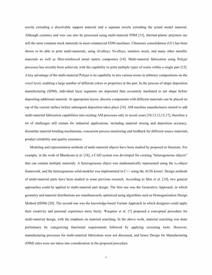
The proposed design for multi-material in additive manufacturing (DfMAM) framework is composed of four
interacting modules. The flowchart of the DfMAM framework is represented in Fig 1. Designers start the design
process by identifying functional requirements and corresponding technical requirements obtained from customers.
In the “primary material selection” module, candidate primary materials are chosen from AM material databases to
achieve multiple design requirements. The appropriate AM processes are then selected to fabricate the product with
previously chosen materials, and corresponding DfAM rules are extracted from the process database. In the final
step, material composition and part geometry are designed to achieve functional requirements while complying
with DfAM rules to ensure manufacturability. The dashed lines in Fig 1 indicate iterations in primary material and
MMAM process selection when the detailed product design (in Module 4) cannot generate satisfactory results. In
the next sections, the interacting modules of the proposed DfMAM framework are discussed in details.
Fig 1: The flowchart of the proposed DfMAM framework
3.1. MODULE 1 – FUNCTIONAL AND TECHNICAL REQUIREMENT IDENTIFICATION
The first stage in multi-material part design is to identify functional requirements of the parts. In general,
market surveys or economic analysis can be conducted to acquire customer voice that indicate the functional
requirement of the product. And then functional analysis is followed to translate the functional requirement into
more specific technical requirements [21] that are fulfilled by proper designs. Analytical tools such as quality
function deployment (QFD) can be applied to analyzing functional requirements [22]. For example, functional and
START Primary material selection
MMAM process selection
Material composition & part
geometry designDesign proposal
Process database
Material database
Functional requirements
Technical requirements
Functional and technical requirement identification
Module 1 Module 2 Module 3 Module 4
6
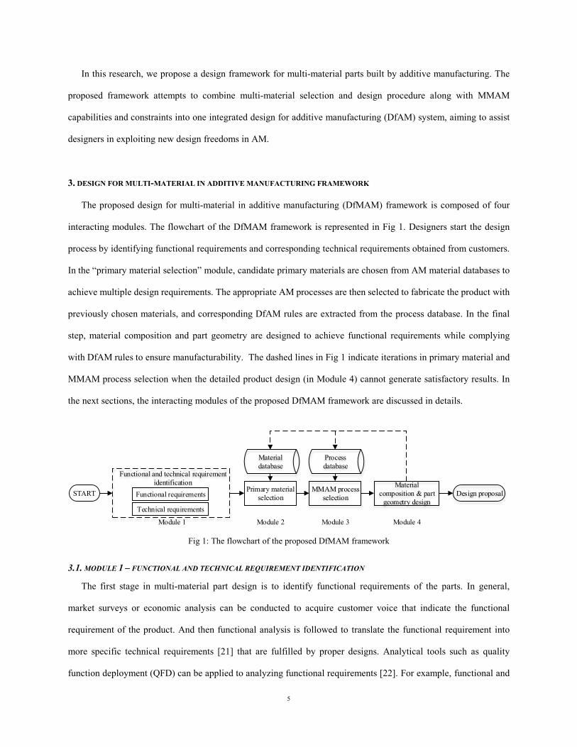
technical requirements for a car engine casing are identified and represented by QFD as shown in Table 1, where
the ● mark indicates strong relationship, ○ mark indicates moderation relationship, and ▽ mark indicates weak
relationship. In the QFD method, the technical requirements with the ● marks in the columns are the major design
objectives that need to be achieved by selecting appropriate materials (or multi-material compositions) and part
geometries. When multiple different technical requirements coexist in the design problem, a multi-material part
may have a higher chance to succeed than a single-component par.
Table 1: Functional and technical requirements of a car engine casing
Technical Requirements Functional requirements
Hig
h fa
tigue
resi
stan
ce
Hig
h th
erm
al
cond
uctiv
ity
Ligh
t-wei
ght s
truct
ure
Ligh
t-wei
ght m
ater
ial
Low
raw
mat
eria
l cos
t
Low
man
ufac
turin
g co
st
Com
pact
size
Long lifecycle ● ▽ ▽ ▽ ▽ ▽ ▽ Efficient cooling ▽ ● ▽ ▽ ▽ ▽ ▽
Low fuel consumption ▽ ○ ● ● ▽ ▽ ● Suitable for mass production ▽ ▽ ▽ ○ ● ● ▽
3.2. MODULE 2 – PRIMARY MATERIAL SELECTION
In multi-material part design, each technical requirement generated in Module 1 may be satisfied by an
individual material separately which is to be integrated with other primary materials into the final product.
Therefore, the material selection process for multi-material parts has more freedom than that for mono-material
parts. However, extra constraints specific to multi-material part design should be considered in primary material
selection. One such consideration is the mutual compatibility of dissimilar materials which are to be bonded to
form an integrated part. Only materials with well bonded interface can be determined as suitable primary materials.
Therefore, the mutual compatibility test can serve as a filter in the material selection.
A QFD-based approach has been applied to material selection decision-making process for mono-material
products [22]. This approach outputs a ranking of the shortlisted materials using a scoring system, based on
material properties that can meet technical requirements. In the proposed design framework, the QFD-based
ranking method is extended to select primary materials in multi-material parts. Being different from the original
method in [22], the modified method separates technical requirements into groups, and then each group is used as
7
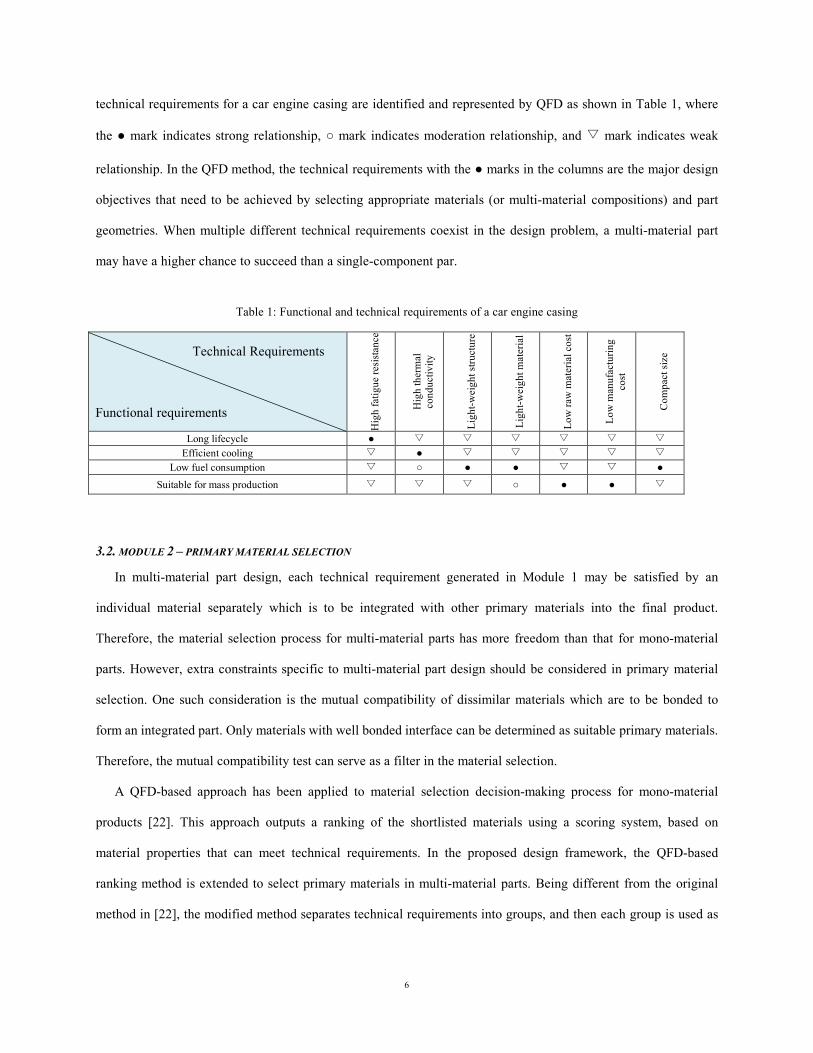
an independent criteria to search for suitable materials. In this manner, multiple groups of technical requirements
will output multiple candidate primary materials. This process is summarized in Fig 2.
Fig 2: Primary material selection module
Candidate primary materials must be selected from the pool of materials that can be processed by MMAM
techniques. An AM-specific material database is required for the selection. The database can be organized based on
material families [23], due to the fact that each different AM technique can process only a limited number of
families of materials.
In some cases, the use of the one material in the product may compromise the product performance created by
the other primary material, and this tradeoff effect must be taken into account in material selection for
multi-material parts. In the example of a multi-material pressure vessel [19] made of metals and ceramics, the use
of ceramics at inner layers may deteriorate the mechanical strength of the metal main body, and the metal-ceramics
interface may also introduce high interfacial stress under temperature fluctuation. Therefore, evaluations need to be
performed to justify the primary selection. Some of these problems may be resolved by choosing proper material
composition functions and part geometry, which will be discussed further in the next section.
3.3. MODULE 3 – MMAM PROCESS SELECTION
Various MMAM processes have been developed. Direct energy deposition processes have been applied to build
functionally graded metal parts, with either continuous or discrete compositional gradient [9]. Binder jet processes
can be used to achieve multi-material compositions by applying different binders within the part volume [11].
AM material database
PolymerMetals Ceramics
Input: technical requirement A
QFD-based ranking method
Input: technical requirement B
Candidates for primary material A
Candidates for primary material B
Compatibility check
Output: primary material A & B
Compatible
Non-compatible Non-compatible
8
Extrusion-based processes can build multi-material parts using multiple extruders [12]. The multi-material polyjet
process has recently been developed to print different resins in the same part [15].
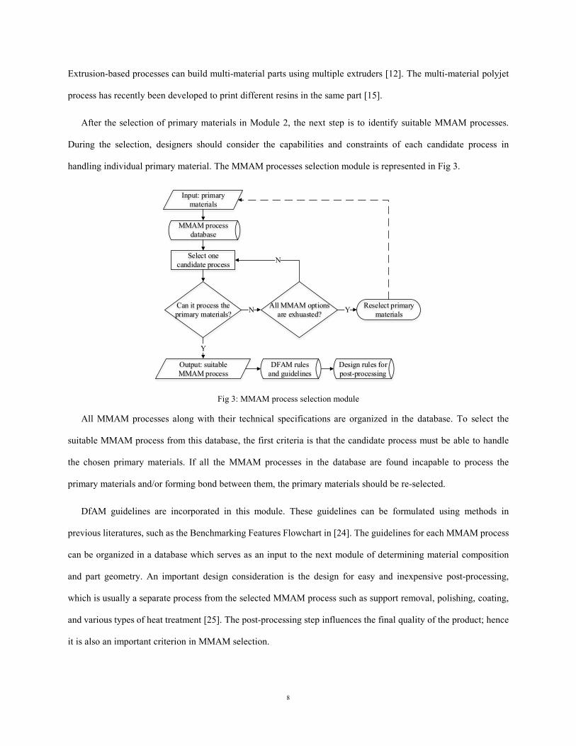
After the selection of primary materials in Module 2, the next step is to identify suitable MMAM processes.
During the selection, designers should consider the capabilities and constraints of each candidate process in
handling individual primary material. The MMAM processes selection module is represented in Fig 3.
Fig 3: MMAM process selection module
All MMAM processes along with their technical specifications are organized in the database. To select the
suitable MMAM process from this database, the first criteria is that the candidate process must be able to handle
the chosen primary materials. If all the MMAM processes in the database are found incapable to process the
primary materials and/or forming bond between them, the primary materials should be re-selected.
DfAM guidelines are incorporated in this module. These guidelines can be formulated using methods in
previous literatures, such as the Benchmarking Features Flowchart in [24]. The guidelines for each MMAM process
can be organized in a database which serves as an input to the next module of determining material composition
and part geometry. An important design consideration is the design for easy and inexpensive post-processing,
which is usually a separate process from the selected MMAM process such as support removal, polishing, coating,
and various types of heat treatment [25]. The post-processing step influences the final quality of the product; hence
it is also an important criterion in MMAM selection.
Input: primary materials
MMAM process database
Select one candidate process
Can it process the primary materials?
DFAM rules and guidelines
Y
N All MMAM options are exhuasted?
N
Y Reselect primary materials
Design rules for post-processing
Output: suitable MMAM process
9
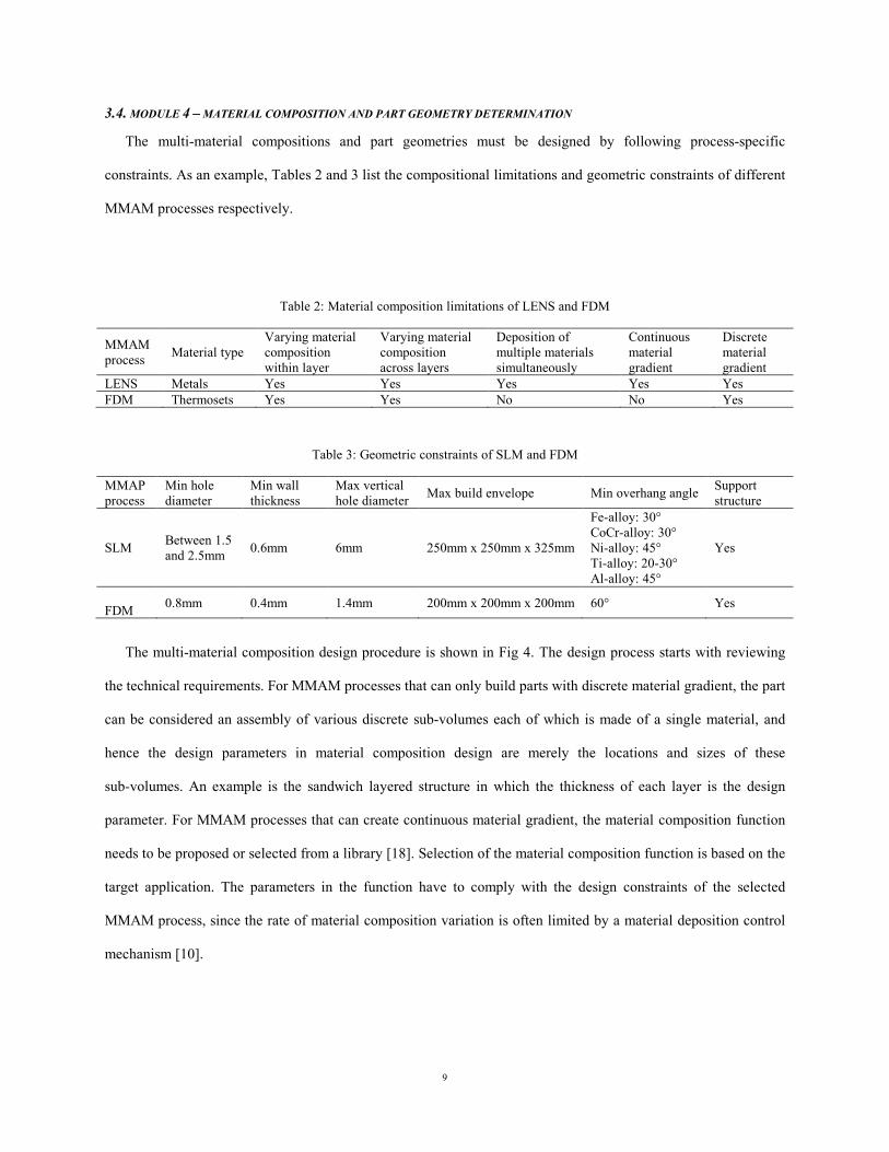
3.4. MODULE 4 – MATERIAL COMPOSITION AND PART GEOMETRY DETERMINATION
The multi-material compositions and part geometries must be designed by following process-specific
constraints. As an example, Tables 2 and 3 list the compositional limitations and geometric constraints of different
MMAM processes respectively.
Table 2: Material composition limitations of LENS and FDM
MMAM process Material type
Varying material composition within layer
Varying material composition across layers
Deposition of multiple materials simultaneously
Continuous material gradient
Discrete material gradient
LENS Metals Yes Yes Yes Yes Yes FDM Thermosets Yes Yes No No Yes
Table 3: Geometric constraints of SLM and FDM
MMAP process
Min hole diameter
Min wall thickness
Max vertical hole diameter Max build envelope Min overhang angle Support
structure
SLM Between 1.5 and 2.5mm 0.6mm 6mm 250mm x 250mm x 325mm
Fe-alloy: 30° CoCr-alloy: 30° Ni-alloy: 45° Ti-alloy: 20-30° Al-alloy: 45°
Yes
FFDM 0.8mm 0.4mm 1.4mm 200mm x 200mm x 200mm 60° Yes
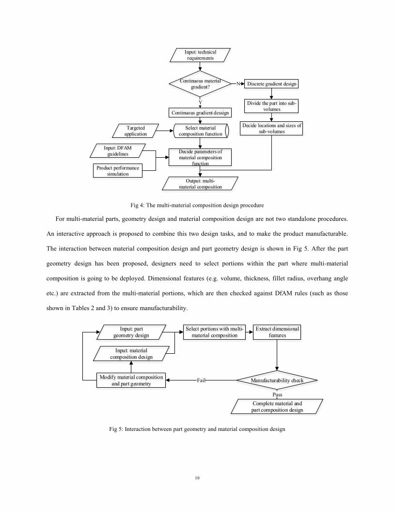
The multi-material composition design procedure is shown in Fig 4. The design process starts with reviewing
the technical requirements. For MMAM processes that can only build parts with discrete material gradient, the part
can be considered an assembly of various discrete sub-volumes each of which is made of a single material, and
hence the design parameters in material composition design are merely the locations and sizes of these
sub-volumes. An example is the sandwich layered structure in which the thickness of each layer is the design
parameter. For MMAM processes that can create continuous material gradient, the material composition function
needs to be proposed or selected from a library [18]. Selection of the material composition function is based on the
target application. The parameters in the function have to comply with the design constraints of the selected
MMAM process, since the rate of material composition variation is often limited by a material deposition control
mechanism [10].
10
Fig 4: The multi-material composition design procedure
For multi-material parts, geometry design and material composition design are not two standalone procedures.
An interactive approach is proposed to combine this two design tasks, and to make the product manufacturable.
The interaction between material composition design and part geometry design is shown in Fig 5. After the part
geometry design has been proposed, designers need to select portions within the part where multi-material
composition is going to be deployed. Dimensional features (e.g. volume, thickness, fillet radius, overhang angle
etc.) are extracted from the multi-material portions, which are then checked against DfAM rules (such as those
shown in Tables 2 and 3) to ensure manufacturability.
Fig 5: Interaction between part geometry and material composition design
Input: technical requirements
Continuous material gradient?
Y
Continuous gradient dessign
N Discrete gradient design
Divide the part into sub-volumes
Decide locations and sizes of sub-volumes
Select material composition function
Targeted application
Input: DFAM guidelines Decide parameters of
material composition function
Product performance simulation
Output: multi-material composition
Input: part geometry design
Select portions with multi-material composition
Extract dimensional features
Manufacturability check
Input: material composition design
FailModify material composition and part geometry
Complete material and part composition design
Pass
11
4. CASE STUDY
The proposed DfMAM framework is illustrated in the case study of designing a cooling plate used in electric
vehicle battery packs. As the power source of electric vehicles, prismatic Li-ion battery cells are usually stacked in
a battery pack to generate sufficient voltage [26]. Efficient thermal management is crucial for the battery’s lifetime
and operation consistency. The battery pack has to keep its temperature below 40°C to ensure safety and durability
of Li-ion batteries [27]. Therefore, cooling plates need to be placed between battery cells to transport heat away
from them [28]. In addition, mechanical strength and weight are also important design concerns for battery packs.
Current cooling plates are usually made of thin metal or highly thermal conductive plastics.
In this case study, a conceptual design of multi-material battery pack cooling plate is introduced to meet both
performance and safety requirements. The steps of the multi-material part design framework introduced in Section
3 are followed during the cooling plate design process, as explained below.
4.1. STEP 1: FUNCTIONAL AND TECHNICAL REQUIREMENT IDENTIFICATION
Functional and technical requirements are determined by interviewing field experts in the electric-car racing
team. Identified design requirements are listed in Table 4, where the ● mark indicates strong relationship, ○ mark
indicates moderation relationship, and ▽ mark indicates weak relationship.
Table 4: Functional and technical requirements of a multi-material battery pack cooling plate
Technical Requirements Functional requirements H
igh
ther
mal
co
nduc
tivity
of
mat
eria
l
Larg
e co
ntac
t are
a w
ith c
oola
nt
Ligh
t-wei
ght
mat
eria
l
Ligh
t-wei
ght
stru
ctur
e
Smal
l the
rmal
ex
pans
ion
Smal
l int
erna
l st
ress
Hig
h im
pact
st
reng
th o
f mat
eria
l
Impa
ct e
nerg
y ab
sorb
ing
stru
ctur
e Efficient cooling ● ● ▽ ● ▽ ▽ ▽ ▽
Light-weight ▽ ▽ ● ● ▽ ▽ ▽ ▽ Maintain structural integrity during normal operation ▽ ▽ ▽ ▽ ● ● ○ ○
Resistant to accidental impact ▽ ▽ ▽ ▽ ▽ ▽ ● ●
4.2. STEP 2: PRIMARY MATERIAL SELECTION
We tried to fulfill the above design requirements by selecting proper primary materials. The candidate materials
are listed in Fig 6. Based on the discussion in Section 4.1, the key property requirements of materials are high
thermal conductivity, low density, and high strength. In this case study of the battery pack cooling plate, we
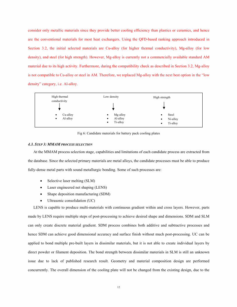
12
consider only metallic materials since they provide better cooling efficiency than plastics or ceramics, and hence
are the conventional materials for most heat exchangers. Using the QFD-based ranking approach introduced in
Section 3.2, the initial selected materials are Cu-alloy (for higher thermal conductivity), Mg-alloy (for low
density), and steel (for high strength). However, Mg-alloy is currently not a commercially available standard AM
material due to its high activity. Furthermore, during the compatibility check as described in Section 3.2, Mg-alloy
is not compatible to Cu-alloy or steel in AM. Therefore, we replaced Mg-alloy with the next best option in the “low
density” category, i.e. Al-alloy.
Fig 6: Candidate materials for battery pack cooling plates
4.3. STEP 3: MMAM PROCESS SELECTION
At the MMAM process selection stage, capabilities and limitations of each candidate process are extracted from
the database. Since the selected primary materials are metal alloys, the candidate processes must be able to produce
fully-dense metal parts with sound metallurgic bonding. Some of such processes are:
• Selective laser melting (SLM)
• Laser engineered net shaping (LENS)
• Shape deposition manufacturing (SDM)
• Ultrasonic consolidation (UC)
LENS is capable to produce multi-materials with continuous gradient within and cross layers. However, parts
made by LENS require multiple steps of post-processing to achieve desired shape and dimensions. SDM and SLM
can only create discrete material gradient. SDM process combines both additive and subtractive processes and
hence SDM can achieve good dimensional accuracy and surface finish without much post-processing. UC can be
applied to bond multiple pre-built layers in dissimilar materials, but it is not able to create individual layers by
direct powder or filament deposition. The bond strength between dissimilar materials in SLM is still an unknown
issue due to lack of published research result. Geometry and material composition design are performed
concurrently. The overall dimension of the cooling plate will not be changed from the existing design, due to the
High thermal conductivity
Low density High strength
• Cu-alloy • Al-alloy
• Mg-alloy • Al-alloy • Ti-alloy
• Steel • Ni-alloy • Ti-alloy
13
dimensional constraint of battery unit cells and the battery compartment in the vehicle. For demonstration purpose,
a simple prismatic plate of 5mm thick is taken as the design reference. Cooling channels are embedded. Al-alloy is
chosen as the main primary material for the cooling plate, with a relatively small amount of Cu-alloy applied in the
area near the inner wall of cooling channels.
As described in Section 3.3, DfAM design rules and guidelines of the LENS process are retrieved from the
database and used in the part geometry design process. For the case of battery pack cooling plate design, important
DfAM rules include the maximum plate size (restricted by the machine’s maximum build envelope) and the
minimum plate thickness (restricted by the minimum printable track width by the LENS nozzle). Post-processing
rules also should be considered in part design. In the LENS process where high thermal stress is caused by laser
induced rapid solidification, as-printed parts will inevitably have distortions which need to be compensated by
post-machining. In addition, the rough surface of parts made by the LENS process need to be grinded to achieve the
desired surface finish. Therefore, sufficient stock (usually more than 1mm) should be added to the part’s designed
dimensions as the machining allowance.
4.4. STEP 4: MATERIAL COMPOSITION AND PART GEOMETRY DETERMINATION
Based on the requirement of avoiding sharp mismatch of thermal expansion rates, a continuous material
gradient is desired at the Al-Cu transition. The material composition functions can either be selected from the
library for specific applications or proposed by the designer. Using the approach from [29], the temperature
distribution in an aluminum cooling plate under the operation condition can be simulated. Although the result from
[29] is based on a single material part, it can help designers understand the heat transfer behavior within the cooling
plate. It can be found that the portion with the highest temperature is the lower-right corner, which locates the inlet
channel. This portion can be made of mainly Cu-alloy which has higher thermal conductivity, while the left portion
near the outlet channel can be made of mainly Al-alloy with slightly lower thermal conductivity but less weight.
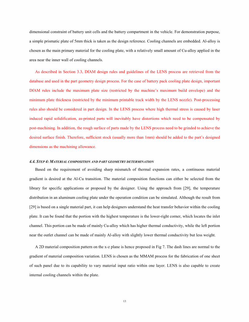
A 2D material composition pattern on the x-z plane is hence proposed in Fig 7. The dash lines are normal to the
gradient of material composition variation. LENS is chosen as the MMAM process for the fabrication of one sheet
of such panel due to its capability to vary material input ratio within one layer. LENS is also capable to create
internal cooling channels within the plate.
14
Fig 7: The cooling plate’s multi-material compositoin on the x-z plane
In a separate design, material composition can also be varied along the y direction. To achieve the functional
requirement of high impact strength, harder materials can be applied to the outer layers of the plate. The material
variation along y direction is shown in Fig 8. Continuous composition gradient is not required across layers.
Therefore, the cooling plate can be deposited by LENS in a whole piece, or can be made by stacking and bonding
several pre-built layers using UC. Most commercial UC machines have built-in CNC modules to achieve high
dimensional accuracy and fine surface finishing. Hence UC is preferred over LENS in the cooling plate fabrication.
Fig 8: The cooling plate’s material composition along the y direction
As illustrated in the case study of conceptual design for a battery pack cooling panel, the proposed DfMAM
framework was able to guide designers through various tasks during the design process for additive manufactured
multi-material parts. Various information/resources about materials and AM processes are coordinated in the
conceptual design process in an orderly manner. Based on the proposed design concepts, more details can be added
to achieve desired performance and manufacturability.
20% Cu – 80% Al
90% Cu – 10% Al
70% Cu – 30% Al
30% Cu – 70% Al 100% Al
x
z
100% (Cu + Al) x
y
50 % (Cu + Al) + 50% Steel
100% Steel
15
5. CONCLUSIONS
In this research, we proposed design for multi-material in additive manufacturing (DfMAM) framework based
on the information of additive manufacturing resources, including processes, materials, and design constraints. The
proposed DfMAM framework integrates four modules: (1) functional and technical requirement identification, (2)
primary material selection, (3) MMAM process selection, and (4) material composition and part geometry
determination. A case study in designing a battery pack cooling plate was conducted to demonstrate the
multi-material design concept. The proposed DfMAM framework can guide designers in exploiting the design
freedoms brought by additive manufacturing.
The present study is at the early stage of exploring a general method for multi-material part design, while the
major limitation is the lack of specific design rules for each specific multi-material additive manufacturing process.
Therefore, in future work, more in-depth investigation of capability and constraints of multi-material part design in
specific AM process will be conducted. And then, a design optimization method may be formulated to search for
the best combinations of material compositions and part geometries. In this paper, the case study in multi-material
cooling plate design is still at the conceptual design level. Future studies can focus on more specific topics, such as
property/performance simulation methods for multi-material parts, computer-aided design (CAD) software with
multi-material part design capability, and multidisciplinary design optimization for multi-material parts with
multi-functionalities.
REFERENCES
1. Gibson I, Rosen DW, Stucker B (2010) Design for Additive Manufacturing. In: Additive Manufacturing Technologies. Springer US, pp 299-332. doi:10.1007/978-1-4419-1120-9_11
2. Ko H, Moon SK, Hwang J (2015) Design for additive manufacturing in customized products. Int J Precis Eng Manuf 16 (11):2369-2375. doi:10.1007/s12541-015-0305-9
3. Yang S, Zhao Y (2015) Additive manufacturing-enabled design theory and methodology: a critical review. Int J Adv Manuf Technol 80 (1-4):327-342. doi:10.1007/s00170-015-6994-5
4. Bin Maidin S, Campbell I, Pei EJ (2012) Development of a Design Feature Database to Support Design for Additive Manufacturing. Assem Autom 32 (3):235-244. doi:10.1108/01445151211244375
5. Nagel JKS, Liou FW (2010) Designing a Modular Rapid Manufacturing Process. Journal of Manufacturing Science and Engineering 132 (6):061006-061006. doi:10.1115/1.4002718
6. Kumke M, Watschke H, Vietor T (2016) A new methodological framework for design for additive
16
manufacturing. Virtual and Physical Prototyping 11 (1):3-19. doi:10.1080/17452759.2016.1139377
7. Wargnier H, Kromm FX, Danis M, Brechet Y (2014) Proposal for a Multi-material Design Procedure. Materials & Design 56 (0):44-49. doi:http://dx.doi.org/10.1016/j.matdes.2013.11.004
8. Oxman N (2011) Variable property rapid prototyping. Virtual and Physical Prototyping 6 (1):3-31. doi:10.1080/17452759.2011.558588
9. Yakovlev A, Trunova E, Grevey D, Pilloz M, Smurov I (2005) Laser-assisted Direct Manufacturing of Functionally Graded 3D Objects. Surface and Coatings Technology 190 (1):15-24. doi:http://dx.doi.org/10.1016/j.surfcoat.2004.07.070
10. Muller P, Mognol P, Hascoet J-Y (2013) Modeling and Control of a Direct Laser Powder Deposition Process for Functionally Graded Materials (FGM) Parts Manufacturing. Journal of Materials Processing Technology 213 (5):685-692. doi:http://dx.doi.org/10.1016/j.jmatprotec.2012.11.020
11. Chiu WK, Yu KM (2008) Direct Digital Manufacturing of Three-dimensional Functionally Graded Material Objects. Computer-Aided Design 40 (12):1080-1093. doi:http://dx.doi.org/10.1016/j.cad.2008.10.002
12. Makerbot (2017) Living on the Cutting Edge with Dualstrusion. http://www.makerbot.com/blog/2013/01/08/living-on-the-cutting-edge-with-dualstrusion/. Accessed 7 Feb 2017
13. Vaezi M, Chianrabutra S, Mellor B, Yang S (2013) Multiple Material Additive Manufacturing – Part 1: a Review. Virtual and Physical Prototyping 8 (1):19-50. doi:10.1080/17452759.2013.778175
14. Ram GDJ, Robinson C, Yang Y, Stucker BE (2007) Use of Ultrasonic Consolidation for Fabrication of Multi-material Structures. Rapid Prototyping Journal 13 (4):226-235. doi:10.1108/13552540710776179
15. Stratasys (2017) Objet500 Connex3 - Vivid Color and Multi-material 3D Printing. http://www.stratasys.com/3d-printers/design-series/precision/objet500-connex3. Accessed 30 Jan 2017
16. Weiss LE, Merz R, Prinz FB, Neplotnik G, Padmanabhan P, Schultz L, Ramaswami K (1997) Shape Deposition Manufacturing of Heterogeneous Structures. Journal of Manufacturing Systems 16 (4):239-248. doi:http://dx.doi.org/10.1016/S0278-6125(97)89095-4
17. Sugavaneswaran M, Arumaikkannu G (2014) Modelling for randomly oriented multi material additive manufacturing component and its fabrication. Materials & Design 54:779-785. doi:10.1016/j.matdes.2013.08.102
18. Bhashyam S, Shin KH, Dutta D (2000) An Integrated CAD System for Design of Heterogeneous Objects. Rapid Prototyping Journal 6 (2):119-135. doi:10.1108/13552540010323547
19. Shin K-H, Natu H, Dutta D, Mazumder J (2003) A Method for the Design and Fabrication of Heterogeneous Objects. Materials & Design 24 (5):339-353. doi:http://dx.doi.org/10.1016/S0261-3069(03)00060-8
20. Bendsøe MP, Kikuchi N (1988) Generating Optimal Topologies in Structural Design Using a Homogenization Method. Computer Methods in Applied Mechanics and Engineering 71 (2):197-224. doi:http://dx.doi.org/10.1016/0045-7825(88)90086-2
21. ElMaraghy H, AlGeddawy T (2014) Multidisciplinary Domains Association in Product Family Design. In: Simpson TW, Jiao J, Siddique Z, Hölttä-Otto K (eds) Advances in Product Family and Product Platform Design. Springer New York, pp 71-89. doi:10.1007/978-1-4614-7937-6_3
22. Prasad K, Chakraborty S (2013) A Quality Function Deployment-based Model for Materials Selection. Materials & Design 49 (0):525-535. doi:http://dx.doi.org/10.1016/j.matdes.2013.01.035

17
23. Ashby MF, Bréchet YJM, Cebon D, Salvo L (2004) Selection Strategies for Materials and Processes. Materials & Design 25 (1):51-67. doi:http://dx.doi.org/10.1016/S0261-3069(03)00159-6
24. Samperi M, Chernow E, Simpson TW, Joshi S, Talbot M (2013) Towards a Process Workflow for Designing and Fabricating Parts Using Additive Manufacturing. Paper presented at the RAPID 2013, Pittsburg, USA, 10-13 Jun 2013
25. Yao X, Moon SK, Bi G (2016) A Cost-Driven Design Methodology for Additive Manufactured Variable Platforms in Product Families. Journal of Mechanical Design 138 (4):041701, doi:10.1115/1.4032504.
26. Li X, He F, Ma L (2013) Thermal Management of Cylindrical Batteries Investigated Using Wind Tunnel Testing and Computational Fluid Dynamics Simulation. Journal of Power Sources 238 (0):395-402. doi:http://dx.doi.org/10.1016/j.jpowsour.2013.04.073
27. Park H (2013) A Design of Air Flow Configuration for Cooling Lithium Ion Battery in Hybrid Electric Vehicles. Journal of Power Sources 239 (0):30-36. doi:http://dx.doi.org/10.1016/j.jpowsour.2013.03.102
28. Jarrett A, Kim IY (2014) Influence of Operating Conditions on the Optimum Design of Electric Vehicle Battery Cooling Plates. Journal of Power Sources 245 (0):644-655. doi:http://dx.doi.org/10.1016/j.jpowsour.2013.06.114
29. COMSOLMultyphysics (2017) Liquid-based Lithium-Ion Battery Pack. COMSOL Multiphysics. http://www.comsol.com/model/download/176039/models.bfc.li_battery_pack_3d.pdf. Accessed 30 Jan 2017


![Multi-task Additive Models for Robust Estimation and Automatic … · group structure identification (CGSI)[26], and Bilevel learning of Group Lasso (BiGL) [12]. 2 Multi-task Additive](https://img.pdfslide.net/doc/110x75/610435c5b2466637a0783aa5/multi-task-additive-models-for-robust-estimation-and-automatic-group-structure-identiication.jpg)