Embed Size (px)
Citation preview

Received: May 25, 2021. Revised: July 12, 2021. 142
International Journal of Intelligent Engineering and Systems, Vol.14, No.5, 2021 DOI: 10.22266/ijies2021.1031.14
A Neural Network based Integer Frequency Offset Estimation and PSS Detection
in 5G NR Systems
Vibha Patel1, 2* Krishna Warhade2
1Gujarat Technological University, Ahmedabad, India
2School of Electronics and Communication Engineering, Dr. Vishwanath Karad MIT World Peace University, Pune, India
* Corresponding author’s Email: [email protected]
Abstract: With an increase in defined carrier frequency for the 5G new radio system, the need for synchronization
also increases. The transceiver loses synchronization due to the occurrence of timing and carrier frequency offsets.
Carrier frequency offsets often occur due to mismatch between transmitter and receiver oscillator frequency as well as
the occurrence of doppler shifts due to transmitter/receiver movements. When frequency offsets exceed subcarrier
spacing, integer frequency offset occurs that results in performance loss due to subcarrier indices shifts. Conventional
approach i.e. maximum likelihood and sequential method is already employed to estimate integer frequency offset and
to detect sector id. In this paper, the deep learning-based method is demonstrated to estimate the integer frequency
offset and sector id detection. The neural network containing multiple convolution layers with activation layers is used
to find the optimum received signal. Then, by calculating the number of cyclic shifts in the optimum received signal,
the integer frequency offset is estimated. Using the corrected optimum received signal, the primary synchronization
signal is also detected that gives sector id. This proposed estimator is tested for different profiles of tapped delay line
models with different desired delay spread and compared with conventional methods i.e. maximum likelihood
estimation method and sequential estimation method. Simulation results show that the proposed Neural Network based
estimator outperforms in all delay profiles.
Keywords: 5G new radio, Integer frequency offset, Primary synchronization signal, OFDM, Neural network.
1. Introduction
The Fifth Generation New Radio (5G NR) system
is a new interface technology developed by the 3rd
Generation Partnership Project (3GPP), an extended
version of the Long Term Evolution-Advance (LTE-
A) standard. It focuses mainly on three use cases,
Ultra-Reliable Low Latency Communication
(URLLC), Enhanced Mobile Broadband (eMBB),
and Massive Machine Type Communications
(mMTC) [1]. To support use cases, 3GPP modified
the physical layer of 5G NR that supports large
bandwidths, Multiple Inputs Multiple
Outputs(MIMO), and Beamforming [1-3]. The
operating bands of 5G NR are classified into two
bands e.g. FR1- sub-6 GHz (below 6GHz) and FR2-
mmWave (above 24GHz) [4]. Orthogonal Frequency
Division Multiplexing (OFDM) is a key technique
used in 3G and 4G Long Term Evolution (LTE)
because it provides high data rate and spectral
efficiency in a multipath environment. To support
services defined in 5G, OFDM numerology is
suitable for 5G NR physical layer [1].
However, OFDM faces major challenges i.e.
Peak to Average Power Ratio (PAPR) and high
sensitivity to timing and frequency offsets. In 5G,
with an increase in defined carrier frequency,
synchronization challenges also increase. Inter-
Carrier Interference (ICI) is increased due to the large
value of timing and frequency offsets. To make
system ICI free, stable, and precise oscillators are
required at the transmitter and receiver side [5, 6]. In
addition to that, Doppler shifts in received signal
occur due to motion of transmitter or receiver results
in performance degradation [7]. Hence, it becomes

Received: May 25, 2021. Revised: July 12, 2021. 143
International Journal of Intelligent Engineering and Systems, Vol.14, No.5, 2021 DOI: 10.22266/ijies2021.1031.14
crucial to address synchronization issues by
estimating and compensating timing offsets and
carrier frequency offsets. Normalized carrier
frequency offsets to subcarrier spacing are divided
into two parts i.e. Fractional Frequency Offsets
(FFOs) and Integer Frequency Offsets (IFOs). Due to
fractional frequency offsets, orthogonality between
subcarriers is destroyed, which leads to performance
degradation. Integer frequency offsets leads to
performance degradation due to the occurrence of
cyclic shift in the frequency domain samples equal to
integer value [8]. Timing offsets and Fractional
Carrier Frequency Offsets (FCFO) are estimated and
corrected before the FFT stage at the receiver side [9].
1.1 Deep learning in wireless communication
Wireless communication technologies are
extensively developed to satisfy the applications and
services in the wireless network. The 5G cellular
network is designed to provide millisecond latency,
thousand-fold capacity, and massive connectivity.
Introduction of new technologies i.e. millimeter
wave (mmWave), Ultra-Dense Network (UDN), and
Multiple Inputs and Multiple Outputs (MIMO) make
system design a more complex task. As stated in [11],
5G focuses on Device to Device communications
(D2D) which increases the data traffic largely,
making conventional communication systems
difficult to operate. In addition to that, conventional
communication system faces limitations to achieve a
high data rate and to handle large data due to reasons
i.e. Difficult channel modelling in complex scenarios,
demand for effective and fast signal processing, and
limited block-structure communication systems.
Machine learning approach is already successful in
the upper layers of the communication system. Deep
learning used at the physical layer will lead to
improved performance as compared to the
conventional communication system.
In [12], the performance of deep learning based
Non Orthogonal Multiple Access (NOMA), MIMO
(Multiple Input Multiple Output), and millimeter-
wave (mmWave) is demonstrated. It is observed that
deep learning methods perform superior to the
conventional communication system.
In this paper, we propose a Neural Network (NN)
estimator for Integer Carrier Frequency Offsets
estimation and Primary Synchronization Signal
(PSS) detection. This proposed estimator is compared
with conventional estimators i.e. Maximum
Likelihood (ML) approach and sequential approach.
The performance of proposed estimator is evaluated
for different delay profiles of Tapped Delay Line
(TDL) channel model with various delay profiles.
The main features of proposed estimator are:
1) The proposed NN estimator consisting
Convolution Neural Network (CNN) layers
and regression layer is trained and tested for
various TDL channel models.
2) The received signals perturbed from IFOs
and channel impairments are given to an
input layer of proposed NN estimator. This
estimator will find optimum received signal
and will calculate number of cyclic shifts in
the signal in order to estimate IFO and to
detect sector ID.
3) This proposed NN estimator gives promising
performance in all TDL delay models as
compared to conventional estimation
schemes and also provides wide IFO
acquisition range of [-3,3]. To consider
various 5G evaluation scenarios shown in
[22], this TDL delay models are scaled to
various delay spreads while training and
testing.
Considering promising future of deep learning based
wireless communication, this proposed NN estimator
could be an encouraging solution to synchronization
problem.
Deep learning approach in wireless
communication is gaining popularity due to its ability
to handle large amount of data and faster data
processing. However, synchronization still remains
critical issue in deep learning based wireless
communication system also. In general,
synchronization is achieved by estimating and
compensating CFOs and timing offsets at appropriate
stage at receiver side. Synchronization issue is
addressed in conventional communication system
through various methods i.e. autocorrelation, cross
correlation and ML estimation. These methods are
discussed in detail in section 2. Recently, the deep
learning approach is employed to estimate CFOs
which is discussed in section 2. Section 3 described
5G system model in detail including structure of
synchronization signal, cell search procedure and
Cyclic Prefix (CP) OFDM signal model. The
proposed NN estimator is illustrated in details in
section 3. In section 4, simulation results of proposed
NN estimator are shown and compared with existing
conventional estimation methods. Performance of
proposed estimator is shown in terms of probability
of failure in estimation of IFO and in detection of
Sector ID. Also, probability of failure over estimation
range is calculated and plotted, which measures

Received: May 25, 2021. Revised: July 12, 2021. 144
International Journal of Intelligent Engineering and Systems, Vol.14, No.5, 2021 DOI: 10.22266/ijies2021.1031.14
performance of proposed estimator over normalized
IFO in different TDL delay profiles.
2. Related work
2.1 Conventional integer frequency offsets
(IFOs) estimation methods
In LTE, many methods are investigated for IFO
estimation using PSS. In [13], the ML method is used
to estimate IFO and sector ID jointly. This method is
proved to be robust in multipath environments and to
residual timing errors due to Approximated
Minimum Mean Square Criterion (AMMSE) reduced
rank presentation of Channel Frequency Response
(CFR). In [14], IFO and sector ID are estimated
sequentially. Proposed method achieves better
accuracy at lower computational complexity as
compared to conventional Maximum Likelihood
(ML) methods. Low complexity joint estimation of
IFO and Cell ID (CID) algorithm is proposed in [15].
Time-domain equalization with Maximum
Likelihood estimation method is used to mitigate ICI
in OFDM. In this paper, the authors achieved superior
performance of TDE method over the conventional
method of frequency domain equalization at low
complexity. [9]
In [10], for 5G systems, autocorrelation and cross
correlation based methods are demonstrated for FFOs
estimation. When Carrier Frequency Offsets (CFOs)
exceed subcarrier spacing then an autocorrelation
based algorithm is used to estimate FFOs and IFOs,
which can be estimated by calculating shifts of the
received synchronization signal. Authors in [16] have
proposed the detection of IFO and Sector ID
sequentially without prior knowledge of PSS for 5G
NR. This scheme provides low complexity at the cost
of slight performance degradation. It uses fact that
three PSS sequences generated for 3 Sector IDs are
cyclically shifted versions of each other.
This existing conventional approach i.e. ML and
sequential estimation for 5G NR system model is
designed for conventional limited block structure
communications. These estimation methods work on
predefined system models and solve estimation
problem by mathematical process [20]. The
estimation accuracy degrades with change in system
model, that results into less compatibility.
2.2 Deep learning based carrier frequency offsets
(CFOs) estimation methods
In [17], CFO of a complex sinusoid is estimated
using Deep Learning (DL) architectures. The
achieved estimation range of CFO is [0.2,0.25].
Deep Neural Network (DNN) based CFO estimation
and packet detection schemes have been investigated
and demonstrated for the emerging IEEE 802.11ah
standard in [18]. In this paper, the Convolution
Neural Network (CNN) and Recurrent Neural
Network (RNN) architectures are used to train the
model. And superior performance of DNN methods
is demonstrated to conventional methods. This
method estimates FFOs in the range [0.5,0.5]. In [19],
authors have proposed a synchronization method
based on Extreme Learning Machine (ELM) to
estimate residual symbol timing offset and residual
carrier frequency offset, which exhibits superior
performance with existing traditional methods. The
performance of the scheme is evaluated under
Additive White Gaussian Noise (AWGN) channels
and frequency selective fading channels.
The NN based coarse CFO estimator is proposed
for multiple inputs and multiple output (MIMO). In
this paper, the estimation problem is transformed into
a classification problem and a training dataset is
generated for normalized CFO range (-0.5,0.5],
which is fractional frequency offsets (FFOs).
Furthermore, the model is trained for the AWGN
channel, slow fading channel, and multipath channel
for the different number of antennas [20]. These all
estimation schemes are designed to estimate FFOs for
different system models to be used in different
applications.
However, to the best of the author’s attention, in
the 5G NR system, deep learning based IFO
estimation is not explored extensively. In this paper,
a Neural Network based estimator is proposed to
estimate IFO and to detect sector ID (SID) for the 5G
NR system. The proposed method is simulated for
different delay profiles of the Tapped Delay Line
(TDL) models scaled to desired delay spread. Here,
the performance of the system is measured in terms
of the probability of failure. The neural network is
trained for IFO range [-3,3] and different delay
profiles of TDL channel model. An infinite signal to
noise ratio (SNR) is considered to avoid noise
disturbance in the training process.
3. System model
3.1 Synchronization signal
As in LTE, User equipments (UEs) of 5G NR
system also uses Primary Synchronization Signal
(PSS) and Secondary Synchronization Signal (SSS)
to detect frame boundary, sector identity (SID), and
cell identity (CID) [1]. The structure of the
Synchronization Signal Block (SSB) is shown in

Received: May 25, 2021. Revised: July 12, 2021. 145
International Journal of Intelligent Engineering and Systems, Vol.14, No.5, 2021 DOI: 10.22266/ijies2021.1031.14
Figure. 1 Synchronization signal block (SSB) for resource
allocation
Fig. 1. PSS is transmitted on the 0th OFDM symbol
followed by PBCH, SSS is transmitted on 2nd, 3rd, 4th
OFDM symbols respectively. The SSB consists of
240 contiguous subcarriers (20 resource blocks),
from which PSS symbols are transmitted on 144
subcarriers.
In 5G, each cell has a unique cell identity (CID)
number from 1008 cell IDs. These cells are arranged
into 336 different groups represented as Group
identity (GID). Each group is identified by three
different sectors which are denoted by Sector identity
(SID). The gNodeB transmits PSS and SSS
periodically, which are used by the UEs to detect
frame boundary and sector ID, synchronize, and
identify the network.
PSS contains the SID index i.e. uϵ{0,1,2} and SSS
contains the GID index i.e. vϵ{0,1,2,…, 335}.
The serving CID is given by
NID= 3u+v (1)
Where u is integer valued SID and u ϵ {0,1,2}, v is
integer valued GID and v ϵ {0,1, 2….,335}.
Similar to 4G networks, for 5G NR, PSS helps UEs
to detect sector ID e.g. u, and to get radio frame
boundary. NR PSS signal is assigned on the first
symbol of each SSB and consists of one of three 127-
symbols m-sequences. The three possible m-
sequences are defined as below [1]
𝑑𝑃𝑆𝑆(𝑛) = 1 − 2𝑥(𝑚), (2)
Where,
𝑚 = [𝑛 + 43𝑢] 𝑚𝑜𝑑 127, 0 ≤ 𝑛 < 127 (3)
𝑥(𝑖 + 7) = [𝑥(𝑖 + 4) + 𝑥(𝑖)]𝑚𝑜𝑑 2, (4)
and,
[𝑥(6) 𝑥(5) 𝑥(4) 𝑥(3) 𝑥(2) 𝑥(1) 𝑥(0)] =[1 1 1 0 1 1 0] (5)
These PSS symbols are transmitted on 56 to 182
subcarriers out of 240 subcarriers.
The 5G NR SSS is used to detect cell ID (CID) and
has 336 combinations defined as below [1]
𝑑𝑆𝑆𝑆(𝑛) = [1 − 2𝑥0([𝑛 + 𝑚0]𝑚𝑜𝑑 127)] × [1 − 2𝑥1([𝑛 + 𝑚1] 𝑚𝑜𝑑 127)] (6)
Where,
𝑚0 = 15[𝑣 112⁄ ] + 5𝑢 (7)
𝑚1 = 𝑣 𝑚𝑜𝑑 112, 0 ≤ 𝑛 ≤ 127 (8)
𝑥0(𝑖 + 7) = [𝑥0(𝑖 + 4) + 𝑥0(𝑖)]𝑚𝑜𝑑 2 (9)
𝑥1(𝑖 + 7) = [𝑥1(𝑖 + 4) + 𝑥1(𝑖)]𝑚𝑜𝑑 2 (10)
[𝑥0(6)𝑥0(5)𝑥0(4)𝑥0(3)𝑥0(2)𝑥0(1)𝑥0(0)] = [0 0 0 0 0 0 1] (11)
and,
[𝑥1(6)𝑥1(5)𝑥1(4)𝑥1(3)𝑥1(2)𝑥1(1)𝑥1(0)] =
[0 0 0 0 0 0 1] (12)
3.2 Cell search procedure
The 5G NR synchronization and cell search
procedure are summarized in Fig. 2. First, timing,
fractional frequency offsets, and frame timings are
estimated and corrected in the time domain using
autocorrelation and cross-correlation methods. Then,
received corrected time-domain samples are
converted into the frequency domain using FFT.
After this, IFO is estimated by evaluating the
frequency domain shifts in the received signal. After
IFO correction, Sector ID u is detected by cross-
correlating corrected received signal with 3 different
m sequences, which represents sequence for sector ID
0,1 and 2. After PSS detection, cell id group v (GID)
is detected using SSS and SID. Hence, serving cell id
Figure. 2 Synchronization and cell search procedure

Received: May 25, 2021. Revised: July 12, 2021. 146
International Journal of Intelligent Engineering and Systems, Vol.14, No.5, 2021 DOI: 10.22266/ijies2021.1031.14
can be calculated using Eq. (1). Here, the focus is on
estimation of IFO and PSS detection using a neural
network.
3.3 Signal model
The Cyclic Prefix Orthogonal Frequency
Division Multiplexing (CP-OFDM) system is
considered that consists of N subcarriers with
separation Δf in the frequency domain. OFDM
symbol at the transmitter is generated by performing
N point inverse fast Fourier transforms (IFFT) on
modulated complex data. A cyclic prefix (CP) of
length Ncp is added OFDM symbol as a prefix to
avoid Inter Symbol Interference (ISI). Usually, the
length of CP is preferred greater than the channel
delay spread. In 5G, normal and extended CP
configurations are supported [1]. This leads to an
increased time duration of one OFDM symbol, which
results in total time duration Nt=Ncp+N. The
transmitted OFDM symbol sm(n) for the mth period is
given by
𝑠𝑚(𝑛) = ∑ 𝑆𝑚(𝑘)𝑒𝑗2𝜋𝑘𝑛
𝑁𝑁−1𝑘=0 (13)
Where n= -Ncp, -Ncp+1,……, N-1 discrete-time index
Sm(k) is a complex signal transmitted on kth
subcarrier
k= subcarrier index
The transmitted signal is distorted by a multipath
channel which is represented by discrete-time
impulse response hm(n). Then, complex Additive
White Gaussian Noise (AWGN) is added to the
distorted transmitted signal. The received signal is
degraded due to CFO, which is generated due to a
mismatch between transmitter and receiver local
oscillator and doppler effect when transmitter/
receiver is moving. At the receiver side, first, timing
offset and FFOs are estimated and corrected. After
FFT, IFO and sector id are estimated jointly or
sequentially. Here, it is assumed that timing offsets
and FFOs are estimated and corrected [21]. The
received signal in the time domain for the mth period
is given by
𝑦𝑚(𝑛) = 𝑒𝑗2𝜋(𝑛−𝜗)
𝑁 𝑠𝑚(𝑛) ∗ ℎ𝑚(𝑛) + 𝑤𝑚(𝑛) (14)
n= -NCP, -NCP+1,……, N-1.
Where υ is normalized IFO to subcarrier spacing,
hm(n) is channel impulse response, * is convolution
operator and wm(n) is sampled zero mean white
Gaussian noise with variance 𝜎𝑤2 .
Once CP is removed, the time-domain signal is
converted into a frequency-domain signal by
performing FFT on the received signal. The signal in
the frequency domain is given by
𝑌𝑚(𝑘) = 𝐻𝑚(𝑘 − 𝜗)𝑆𝑚(𝑘 − 𝜗)𝑒𝑗2𝜋(𝑘−𝜗)
𝑁 + 𝑊𝑚(𝑘),
|𝜗| ≤ 𝐺,
k=1,2,3,…., N-1 subcarriers (15)
Where Hm(k) is channel frequency response over kth
subcarrier with variance 𝜎𝐻2 , 𝑊𝑚(𝑘) is complex
zero-mean additive white Gaussian noise with
variance 𝜎𝑊2 and υ is the normalized IFO to
subcarrier spacing and G is the maximum value of
IFO.
3.4 Conventional estimation methods
Conventional method to estimate IFO and sector
ID is presented in [13] and [16] for LTE and 5G
system model. In [13], Maximum Likelihood
estimation method is employed to estimate IFO and
to detect PSS. These two parameters are estimated
jointly. In this, the concentrated likelihood function
is maximized for different values of IFO and sector
ID. This concentrated likelihood function is defined
by
�̂�𝑀𝐿 = 𝑎𝑟𝑔𝜑𝑚𝑎𝑥{𝑓(�̂�)} (14)
This likelihood function 𝑓(�̂�) is defined by Eq. (15)
𝑓(�̂�) =1
63‖𝑌𝑚‖2 |∑ 𝑍𝑚(�̂�, 𝑣; 𝑘)31𝑘=−31 | (15)
Where 𝑍𝑚(�̂�, 𝑣; 𝑘) = 𝑌𝑚(𝑘 + 𝑣)𝑑𝑃𝑆𝑆∗(𝑘)
Estimated values will be the ones for which
likelihood function given in Eq. (15) will be
maximized.
In [16], sequential approach is used to estimate
IFO and sector ID. In this, cross correlation is
performed between received signal and summed PSS
sequences. This function is defined as
∅(𝑚) = ∑ 𝑌𝑚(𝑘 + 𝑚)182𝑘=57 �̅�∗(𝑘) (16)
Where �̅�(𝑘) = ∑ 𝐷𝑤(𝑘)2𝑤=0 is summed NR PSS,
m={-3,-2,….,2,3} trial values of IFO and
Dw(k)(w=0,1,2) represents three m sequences. They
proposed method based on the fact that three m

Received: May 25, 2021. Revised: July 12, 2021. 147
International Journal of Intelligent Engineering and Systems, Vol.14, No.5, 2021 DOI: 10.22266/ijies2021.1031.14
sequences are cyclically shifted versions of each
other and therefore cross correlation between any pair
of m sequences is nearly zero. This objective function
is maximized for different hypothesized values of
IFO. The estimated IFO is the one for which objective
function is maximized. The estimated IFO is given by
𝑣 = 𝑎𝑟𝑔𝑚𝑚𝑎𝑥ℜ{∅(𝑚)} (17)
Where ℜ indicates real part of the quantity. After IFO
estimation, Sector ID is sequentially detected using
�̂� = 𝑎𝑟𝑔𝑤 max ℜ{∑ 𝑌𝑚(𝑘 + 𝑣)182𝑘=57 𝐷𝑤
∗ (𝑘)} (18)
Where w ϵ {0,1,2} is trial values of Sector ID.
As discussed here, these conventional estimation
methods are based on predefined system model. Its
performance degrades with change in system model
that results into low compatibility. To provide high
compatibility, deep learning approach is proposed
here.
3.5 Proposed neural network (NN) based IFO
estimation
Here, estimation problem is converted into
regression problem. IFO and sector ID are estimated
and detected using a neural network containing
Convolution Neural Network (CNN) layers and
regression layer as a final layer. The typical CNN is
shown in Fig. 3. The CNN successfully captures
temporal and spatial correlation in the input signal.
Here, 2-D convolution layer is applied on received
input signal. This proposed NN estimator consists of
input layer, hidden layers and output layer. The
regression layer as an output layer calculates half
squared Mean Square Error (MSE). This proposed
neural network is trained for several epochs to
minimize MSE. Due to this, proposed NN estimator
gives optimum performance when the impaired
signal from channel nonlinearities and IFO is given
to this trained network.
This proposed NN estimator takes received signal,
learns estimation rule, and gives the best IFO
candidate near to true IFO. To train the model,
training datasets are generated for different values of
IFO and different TDL channel delay profiles with
various desired delay spreads [22]. The training
datasets are divided into training data and validation
data to avoid overfitting. First, the model is trained
using training data and then examines the
performance using validation data. The loss function
is minimizing during the next epochs. After the
Figure. 3 Typical structure of convolution neural network
model is trained, test data set is given to trained NN
estimator to find optimal IFO nearest to true IFO and
sector ID.
CNN based IFO estimator accepts real and
complex valued received signals separately. The
architecture of NN based IFO estimator is shown in
Fig. 4. The received signal is separated into real and
imaginary dataset. In the next convolution layer, the
column vector of 432 symbols is processed by 250
9x9 filters of convolution layers with a Rectified
Linear Unit (ReLU) activation function to generate
250 outputs. Subsequently, six convolution layers of
5x5 filters
Figure. 4 NN based IFO estimator architecture

Received: May 25, 2021. Revised: July 12, 2021. 148
International Journal of Intelligent Engineering and Systems, Vol.14, No.5, 2021 DOI: 10.22266/ijies2021.1031.14
are used followed by ReLU activation. At the output
layer, an estimated real and imaginary part of the
received signal is obtained that is nearer to true values
of the real and imaginary part of the perturbed signal
with IFO.
After this, estimated IFO can be calculated by
finding the number of cyclic shifts in the estimated
received signal by NN. The estimated received signal
is corrected by estimated IFO in order to detect sector
ID. The sector ID is detected by correlating corrected
received sequence and three m-sequences.
4. Results and discussion
For simulation, a 40 MHz 5G NR system is
considered with the number of subcarriers N=512,
symbol duration Ts= 0.016μs, Δf=30KHz which is
operating at 6 GHz [16]. As per normal mode, a
cyclic prefix of 44 symbols length is added. PSS of
127 symbols is transmitted on 56 to 182 subcarriers
out of 240 subcarriers. For 5G channel model, the
tapped delay line (TDL) model is considered with
different delay profiles. These delay profiles are
classified into Non-Line of Sight (NLOS) i.e. TDL-
A, TDL-B, TDL-C, and Line of sight (LOS) i.e. TDL-
D, TDL-E models. Power delay profiles of these
channel models are described in [22]. Here,
normalized IFO value is considered from -3 to 3, by
considering the stability of commercial oscillator of
±20 ppm for mobile applications [16]. Here, the
performance of the estimation of IFO and sector id is
separately shown. The performance metric is the
probability of failure that is expressed as Pfv =
Prob{(𝑣) ≠ (v)} for IFO and Pfu = Prob{(�̂�) ≠ (u)} for
Sector ID. The simulation parameters are shown in
Table 1.
Here, the training dataset is generated across
normalized IFO range [-3,3] with resolutions of 1 and
for 5 channel models as discussed earlier. There are
127 symbols in the PSS signal on 56 to 182
subcarriers. In training process, to avoid disturbance
from noise, SNR is set to an infinite value. The
proposed NN is trained for random value of IFO
selected from the interval [-3,3], and for randomly
selected delay profiles. These generated delay
profiles can be scaled to desired delay spread. We
considered here five cases of delay spread very short
delay spread (10ns), short delay spread (30ns),
nominal delay spread (100ns), long delay spread
(300ns), and very long delay spread (1000ns) while
training the neural network.
In this way, 1,00,000 frames for training datasets
are generated and these frames are perturbed from
random IFO and random TDL profile with desired
Table 1. Simulation parameters
Parameter Value
Carrier frequency 40 MHz
Symbol duration Ts 0.016μs
Subcarrier spacing 30KHz
Guard Interval Ng 44
FFT size, NFFT 512
Channel Model Tapped Delay Line (TDL)
TDL delay profiles TDL-A, TDL-B, TDL-
C,TDL-D, TDL-E
scaled delay spread. Frequency selective fading
environment is selected for training as well as testing
purpose.
The batch size is set to 1000 in the training of the
proposed NN estimator. Test data is given to the
proposed NN estimator and tested for SNR value
from -6dB to 15dB and for different delay profiles.
While testing, NLOS and LOS delay profiles are
scaled with various delay spreads is selected to
validate results in different scenarios. These
simulation results are compared with the traditional
ML estimator presented in [13] and sequential
estimator presented in [16].
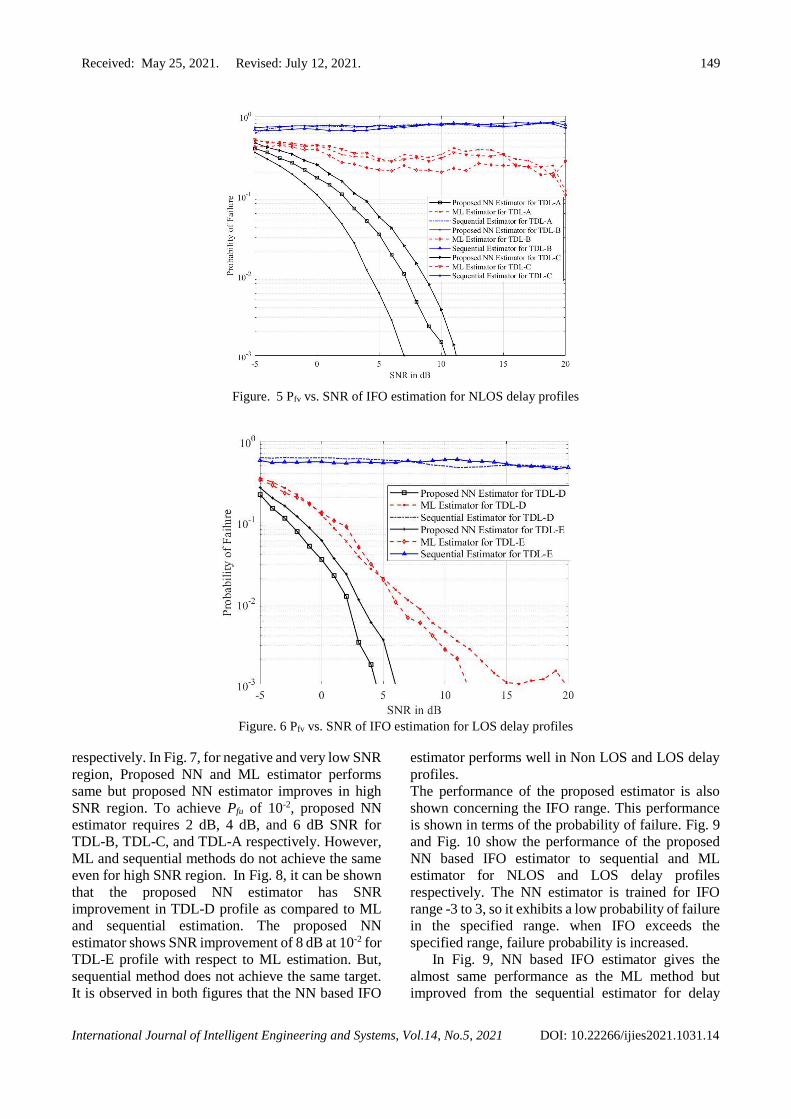
In Fig. 5, performance of the proposed NN
estimator, ML method, and sequential method is
shown for NLOS delay profiles TDL-A, TDL-B, and
TDL-C. It is seen that the proposed NN estimator
outperforms in all delay profiles as compared to ML
and sequential methods. The proposed NN estimator
achieves less probability of failure in less than 11 dB
region for NLOS delay profiles. At failure probability
of “10-2”, proposed NN estimator realizes 4 dB, 7dB
and 9 dB SNR in TDL-B, TDL-A and TDL-C delay
profiles respectively. However, ML and sequential
methods fails to achieve same failure probability.
Fig. 6 shows the performance of the proposed NN
based IFO estimator and conventional methods for
LOS delay profiles TDL-D and TDL-E. The
proposed scheme again performs well and
exceptionally well in all delay profiles concerning
ML and sequential estimation respectively. The
proposed scheme has an SNR improvement of 5dB to
ML estimation. For the negative SNR region, the NN
estimator also performs well. Proposed estimator
achieves “10-2” failure probability at SNR 3dB and
4dB in TDL-D and TDL-E delay profiles respectively.
The same can be achieved at 6dB and 7dB SNR in
ML method. However, sequential method fails to
achieve same probability of failure.
In Fig. 7 and Fig. 8, the performance of the
proposed NN based IFO estimator to ML and
sequential method for sector ID estimation in
presence of Non LOS and LOS delay profiles
Received: May 25, 2021. Revised: July 12, 2021. 149
International Journal of Intelligent Engineering and Systems, Vol.14, No.5, 2021 DOI: 10.22266/ijies2021.1031.14
Figure. 5 Pfv vs. SNR of IFO estimation for NLOS delay profiles
Figure. 6 Pfv vs. SNR of IFO estimation for LOS delay profiles
respectively. In Fig. 7, for negative and very low SNR
region, Proposed NN and ML estimator performs
same but proposed NN estimator improves in high
SNR region. To achieve Pfu of 10-2, proposed NN
estimator requires 2 dB, 4 dB, and 6 dB SNR for
TDL-B, TDL-C, and TDL-A respectively. However,
ML and sequential methods do not achieve the same
even for high SNR region. In Fig. 8, it can be shown
that the proposed NN estimator has SNR
improvement in TDL-D profile as compared to ML
and sequential estimation. The proposed NN
estimator shows SNR improvement of 8 dB at 10-2 for
TDL-E profile with respect to ML estimation. But,
sequential method does not achieve the same target.
It is observed in both figures that the NN based IFO
estimator performs well in Non LOS and LOS delay
profiles.
The performance of the proposed estimator is also
shown concerning the IFO range. This performance
is shown in terms of the probability of failure. Fig. 9
and Fig. 10 show the performance of the proposed
NN based IFO estimator to sequential and ML
estimator for NLOS and LOS delay profiles
respectively. The NN estimator is trained for IFO
range -3 to 3, so it exhibits a low probability of failure
in the specified range. when IFO exceeds the
specified range, failure probability is increased.
In Fig. 9, NN based IFO estimator gives the
almost same performance as the ML method but
improved from the sequential estimator for delay

Received: May 25, 2021. Revised: July 12, 2021. 150
International Journal of Intelligent Engineering and Systems, Vol.14, No.5, 2021 DOI: 10.22266/ijies2021.1031.14
Figure. 7 Pfu vs. SNR of Sector ID estimation for Non-LOS delay profiles
Figure. 8 Pfu vs. SNR of Sector ID estimation for LOS delay profiles
profiles TDL-A, TDL-B and TDL-C. In Fig. 10, the
proposed NN estimator performs well as compared to
the conventional methods for the specified IFO range.
In all simulation results, it can be observed that the
proposed NN estimation method works efficiently
and gives less failure probability in all channel delay
profiles. This occurs due to a proposed neural
network is trained with different channel delay
profiles and for different IFO values from -3 to 3.
And the trained neural network will find optimal
received sequence when test data is given. These all
delay profiles are scaled to appropriate delay spread
and the proposed estimation method tested for the
same.
5. Conclusion
In this paper, we propose NN based IFO
estimation and PSS detection for the 5G NR system.
The deep learning approach is employed over
conventional methods to estimate IFO and to detect
PSS. This proposed estimator is tested for different
delay profiles of TDL channel and compared with
conventional method ML and sequential estimation.
These delay profiles are scaled with various desired

Received: May 25, 2021. Revised: July 12, 2021. 151
International Journal of Intelligent Engineering and Systems, Vol.14, No.5, 2021 DOI: 10.22266/ijies2021.1031.14
Figure. 9 Pf vs. Normalized IFO for NLOS delay profiles
Figure. 10 Pf vs. Normalized IFO for LOS delay profiles
delay spreads. From simulation results, it is
affirmatively proved that the proposed NN estimator
outperforms in all channel models. With an increase
in the deep learning approach for the physical layer
of 5G NR, this proposed method for estimation of
IFO and detection of PSS could be employed to
reduce synchronization errors.
Conflicts of interest
The authors declare no conflict of interest
Author contributions
Vibha Patel, the first author contributed in
conceptualization, methodology, software, validation,
formal analysis, investigations, writing—original
draft preparation, writing—review and editing and
visualization.
Krishna Warhade, the second author supervised
and administered project.

Received: May 25, 2021. Revised: July 12, 2021. 152
International Journal of Intelligent Engineering and Systems, Vol.14, No.5, 2021 DOI: 10.22266/ijies2021.1031.14
References
[1] 3GPP TS 38.211, NR; Physical Channels and
Modulation (Release 15), Version.15.4.0, pp. 1-
97 ,2019.
[2] 3GPP TS 38.212, NR; Multiplexing Channel
Coding (Release 15), Version.15.4.0, pp. 1-102,
2019
[3] 3GPP TS 38.213, NR; Physical Layer
Procedures for Control (Release 15),
Version.15.4.0, pp. 1-105, 2019
[4] 3GPP TS 38.104, NR; Base Station (BS) radio
transmission and reception (Release 15),
Version 15.2.0, pp. 1-155, 2018
[5] H. Abdzadeh-Ziabari, W. Zhu and M. N. S.
Swamy, “Joint Maximum Likelihood Timing,
Frequency Offset, and Doubly Selective
Channel Estimation for OFDM Systems”, IEEE
Transactions on Vehicular Technology, Vol. 67,
No. 3, pp. 2787-2791, 2018.
[6] D. Li, Y. Li, H. Zhang, L. J. Cimini, and Y. Fang,
“Integer Frequency Offset Estimation for
OFDM Systems with Residual Timing Offset
Over Frequency Selective Fading
Channels”, IEEE Transactions on Vehicular
Technology, Vol. 61, No. 6, pp. 2848-2853,
2012.
[7] L. Cheng, B. Henty, F. Bai, and D. D. Stancil,
“Doppler spread and coherence time of rural and
highway vehicle-to-vehicle channels at 5.9
GHz”, In: Proc. of 2013 IEEE Global
Telecommunications Conference, LA, USA, pp.
1-6, 2008.
[8] P. K. Nishad and P. Singh, “Carrier frequency
offset estimation in OFDM systems”, In: Proc.
of 2013 IEEE Conference on Information &
Communication Technologies, Thuckalay, India,
pp. 885-889, 2013.
[9] S. Tanangsanakool, P. Reangsuntea, K Mori,
and P. Boonsrimuang, “Low-Complexity based
TDE Method for OFDM Signal in Higher Time-
Varying Fading Channels”, International
Journal of Intelligent Engineering & Systems,
Vol. 13, No.4, pp. 21-32, 2020.
[10] A. Omri, M. Shaqfeh, A. Ali, and H. Alnuweiri,
“Synchronization Procedure in 5G NR Systems”,
in IEEE Access, Vol. 7, pp. 41286-41295, 2019.
[11] T. Wang, C. K. Wen, H. Wang, F. Gao, T. Jiang,
and S. Jin, “Deep learning for wireless physical
layer: Opportunities and challenges”, China
Commun., Vol. 14, No. 11, pp. 92-111, 2017.
[12] H. Huang, S. Guo, G. Gui, Z. Yang, J. Zhang, H.
Sari, and F. Adachi, “Deep Learning for
Physical-Layer 5G Wireless Techniques:
Opportunities, Challenges and Solutions”, IEEE
Wireless Communications, Vol. 27, No.1, pp.
214-222, 2020.
[13] M. Morelli and M. Moretti, “A Robust
Maximum Likelihood Scheme for PSS
Detection and Integer Frequency Offset
Recovery in LTE Systems”, IEEE Transactions
on Wireless Communications, Vol. 15, No. 2, pp.
1353-1363, 2016.
[14] C. Chu, I. Lai, Y. Lan, and T. Chiueh, “Efficient
Sequential Integer CFO and Sector Identity
Detection for LTE Cell Search”, IEEE Wireless
Communications Letters, Vol. 3, No. 4, pp. 389-
392, 2014.
[15] Y. A. Jung, D. Shin, and Y. H. You, “A
Computationally Efficient Joint Cell Search and
Frequency Synchronization Scheme for LTE
Machine-Type Communications”, Symmetry,
Vol. 11, No. 11, p. 1394, 2019.
[16] Y. H. You and H. K. Song, “Efficient Sequential
Detection of Carrier Frequency Offset and
Primary Synchronization Signal for 5G NR
Systems”, in IEEE Transactions on Vehicular
Technology, Vol. 69, No. 8, pp. 9212-9216,
2020.
[17] R. M. Dreifuerst, R. W. Heath, M. N. Kulkarni,
and J. Charlie, “Deep Learning-based Carrier
Frequency Offset Estimation with One-Bit
ADCs”, In: Proc. of 2020 IEEE 21st
International Workshop on Signal Processing
Advances in Wireless Communications
(SPAWC), GA, USA, pp. 1-5, 2020.
[18] V. Ninkovic, D. Vukobratovic, A. Valka, and D.
Dumic, “Deep learning based packet detection
and carrier frequency offset estimation in IEEE
802.11ah”, arXiv, identifier arXiv: 2004.
11716v1, 2020.
[19] J. Liu, K. Mei, X. Zhang, D. McLernon, D. Ma,
J. Wei, and S. A. R. Zaidi, “Fine timing and
frequency synchronization for MIMO-OFDM:
An extreme learning approach”, submitted
to IEEE Transactions on Wireless
Communications, identifier arXiv: 2007. 09248.
[20] M. Zhou, X. Huang, Z. Feng, and Y. Liu,
“Coarse Frequency Offset Estimation in MIMO
Systems Using Neural Networks: A Solution
with Higher Compatibility”, in IEEE Access,
Vol. 7, pp. 121565-121573, 2019.
[21] J. J. V D Beek, M. Sandell, and P. O. Borjesson,
“ML estimation of time and frequency offset in

Received: May 25, 2021. Revised: July 12, 2021. 153
International Journal of Intelligent Engineering and Systems, Vol.14, No.5, 2021 DOI: 10.22266/ijies2021.1031.14
OFDM systems”, in IEEE Transactions on
Signal Processing, Vol. 45, No. 7, pp. 1800-
1805, 1997.
[22] 3GPP TR 38.900, 5G; Study on channel model
for frequency spectrum above 6 GHz (Release
14), Version 14.2.0, pp. 1-88, 2017