Embed Size (px)
Citation preview
A New Approach Applied to a Thermal Power Plant Controller Using Fuzzy Logic
HAMID BENTARZI*, RABAH AMR CHENTIR* NADIR BELAIDI* SAMAH DIF*
and NIKOS E.MASTORAKIS**
*Signals and Systems Laboratory (SiSyLAB) DGEE, FSI, Boumerdes University
ALGERIA **Technical University of Sofia,
English Language Faculty of Engineering Department of Industrial Engineering
BULGARIA
Abstract: - This work presents a new approach for controlling dynamic parameters of thermal power plant using Fuzzy logic. The control strategy is based on supervisor level using Fuzzy logic that is required to determine automatically the optimal process set points of regulations level. A thermal power plant simulator has been developed through the use of Matlab-Simulink. Besides, this paper describes hardware implementation using PLC based DCS. Key-Words: - Thermal power plant, Coordinated Control Mode, Optimal Controller, DCS, Fuzzy Logic.
1 Introduction The number of construction of a new thermal
power plant is relatively reduced. However, thermal power plants account for approximately 65% of the world’s power supply. Recently, there have been concerns regarding the efficiency improvement of existing thermal power plants. The efficiency of such type of power plant is very low and great amount of loss in thermal energy may be noticed [1]. In order to generate a required electric energy, the turbine needs an equivalent amount of thermal energy in addition to the loss. Minimizing the loss leads to a reduction of pollutants in the environment as well as production cost. Steam is merely a vehicle which transports the energy from the burners to the turbine shaft. The flow of steam is not only the parameter that should be determined, but also the temperature and the pressure must be taken into consideration for a given value of power. Nowadays, for improving the efficiency of the thermal power plants, the control strategies with different hierarchical levels have been used. In the high level called supervisor, the control strategies are coordinated and the process set-points are determined for low levels named regulations. However, this work presents a new method of control strategy based on supervisor level that is required to determine automatically the optimal process set points for regulations level using Fuzzy logic. The supervisor level is based on an energy optimizer algorithm implemented in PC and considering the process operational constraints. All the regulations of utilities such as boiler and turbine as well as generator
which are the most important control loops of power plant, have been implemented using PLC’s.
2 A Thermal Power Plant Unit Most thermal power plants generate a power
ranged from 125 MW to 1000 MW power. They generally consist of three main elements which are boiler, turbine, and alternator, and other complementary accessories such as a fuel handling system transformer, water handling, and emission control system. 2.1 Process Description
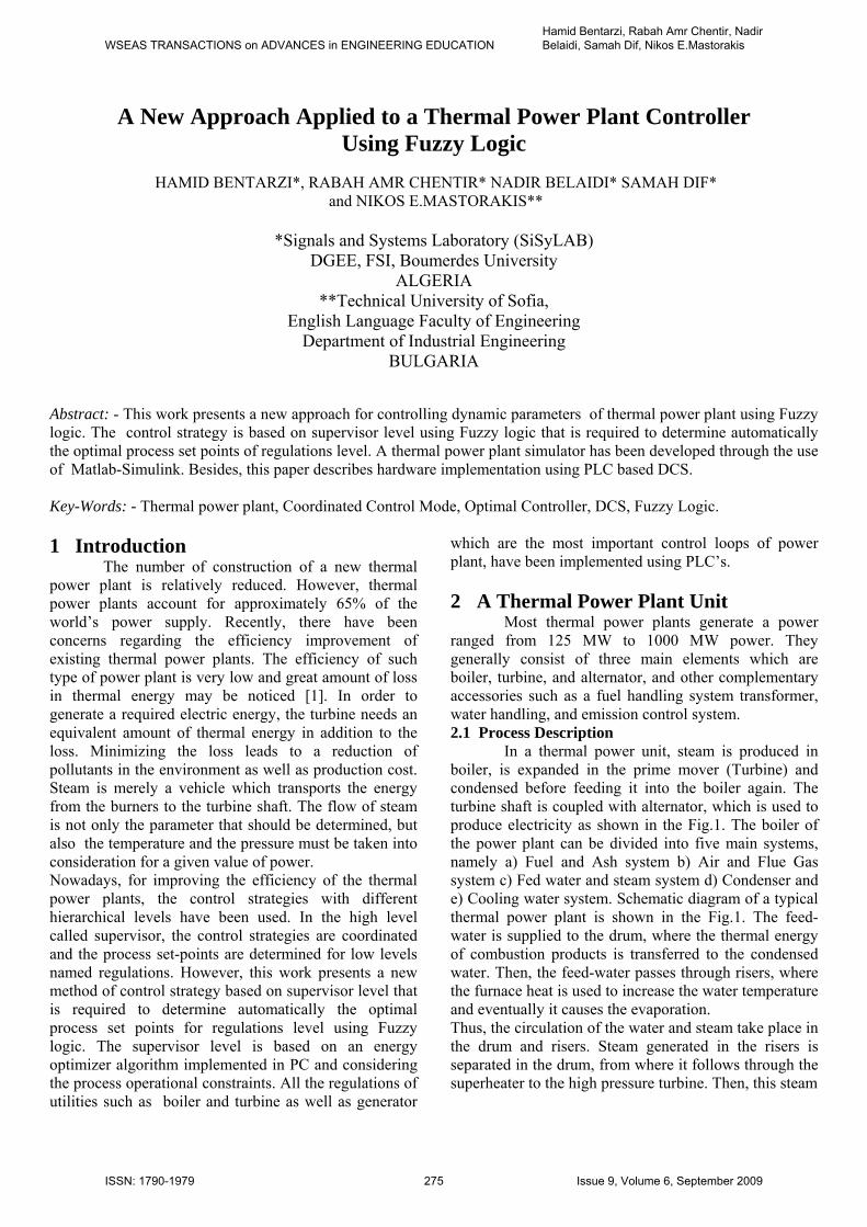
In a thermal power unit, steam is produced in boiler, is expanded in the prime mover (Turbine) and condensed before feeding it into the boiler again. The turbine shaft is coupled with alternator, which is used to produce electricity as shown in the Fig.1. The boiler of the power plant can be divided into five main systems, namely a) Fuel and Ash system b) Air and Flue Gas system c) Fed water and steam system d) Condenser and e) Cooling water system. Schematic diagram of a typical thermal power plant is shown in the Fig.1. The feed-water is supplied to the drum, where the thermal energy of combustion products is transferred to the condensed water. Then, the feed-water passes through risers, where the furnace heat is used to increase the water temperature and eventually it causes the evaporation. Thus, the circulation of the water and steam take place in the drum and risers. Steam generated in the risers is separated in the drum, from where it follows through the superheater to the high pressure turbine. Then, this steam
WSEAS TRANSACTIONS on ADVANCES in ENGINEERING EDUCATIONHamid Bentarzi, Rabah Amr Chentir, Nadir Belaidi, Samah Dif, Nikos E.Mastorakis
ISSN: 1790-1979 275 Issue 9, Volume 6, September 2009
is recycled to the boiler in the reheater where its energy content is increased. The turbine is a mechanical device that converts thermal energy from pressurized steam into useful mechanical energy to rotate the shaft. The turbine makes use of the fact that steam, when passing through a small opening, attains a high velocity. The attained velocity during expansion depends on the initial and final heat content of the steam. This difference in heat content represents the heat energy converted into kinetic energy (energy due to velocity) during the process. The turbine is composed of: high, intermediate and low pressure cores. 2.2 Process Modeling
The main assumptions and equations of the thermal power plant components are presented [2-5]. The boiler equations are based on the following assumptions: -Polynomials approximations of steam tables are used to establish the relations between the steam parameters, such as the enthalpy, density, temperature and pressure. - The superheated and the exhaust gases of the furnace are considered as ideals. Under these above mentioned assumptions, the following physical thermodynamic equations may be satisfied. Heat balance
)( ououououininin hdtdVhwhwQ
(1) Where, Qin is incoming heat flow, win inlet mass flow, hin inlet specific enthalpy, wou outlet mass flow, hou outlet specific enthalpy. Mass balance
)( ououindtdVww
(2)
Then, the main equations of steam turbine are given by : Mass balance for steam
)( ooidtdVww
(3) where, wi is inlet steam flow, wo outlet steam flow, Heat balance for steam
)( ooooii hdtdVhwhw
(4) Where hi inlet steam specific enthalpy and ho is outlet steam specific enthalpy. When starting the turbine, the speed is controlled until the generated power frequency reaches the desired one; during this time the generator is not connected to the electric network. When the desired frequency is reached (50 Hz), the generator is synchronized with the electric network by mean of the synchronizer, and coupled to the electric network. At this time, the power controller controls of the turbine to supply the necessary power to the network. The power controller acts also on the valves of the turbine’s inlet, but this time the position of the valves is controlled to increase or decrease the torque exerted by the turbine (τturbine), to make it equivalent to the torque exerted by the load (τload.)on the network. This is summarized in Eq.(5). When τturbine= τload. => The speed/frequency is constant in the network.
dtdIloadturbine (5)
where, I is inertia moment of the rotor and ω angular speed of the rotor (Rad/Sec). The relation between the speed of the Turbine shaft and the frequency of the generator is given by:
PNf
S60 (6)
where, S is the speed of the turbine in RPM and NP the number of the rotor poles. The mechanical power that is converted into electrical power is given the relation:
turbineP (7)
Fig.2 Coordinate control mode.
Fig.1 Schematic layout of a typical power plant.
WSEAS TRANSACTIONS on ADVANCES in ENGINEERING EDUCATIONHamid Bentarzi, Rabah Amr Chentir, Nadir Belaidi, Samah Dif, Nikos E.Mastorakis
ISSN: 1790-1979 276 Issue 9, Volume 6, September 2009
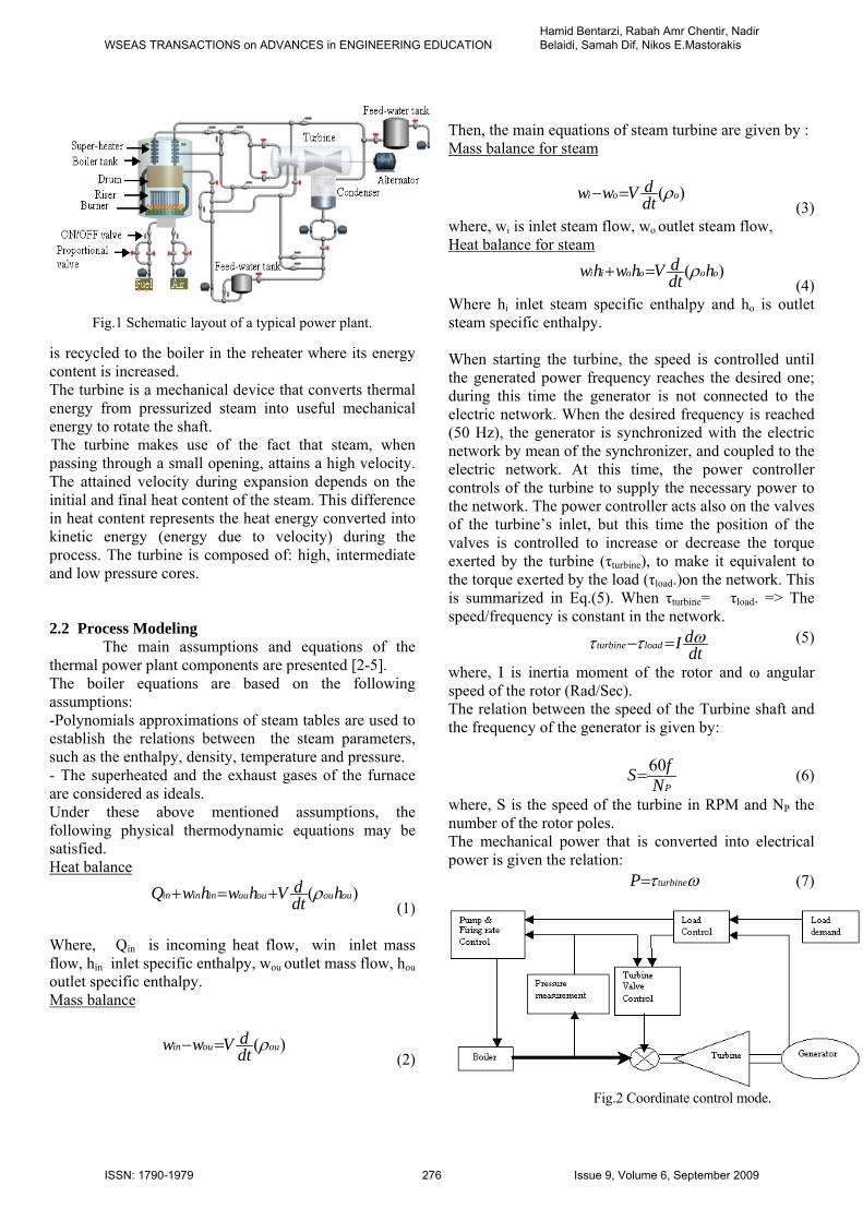
Fig.3 : Block diagram of distributed control system. 2.3 An Existing Control Strategy
The most modern thermal generation plants use a control scheme that is usually named an integrated or coordinated control system. This type of controller simultaneously adjusts firing rate, pumping rate, and turbine throttling in order to follow changes in load demand. Such a coordinated control mode is shown in Fig.2. In this type of control, both pressure and generated output are fed back for the control of both boiler and turbine. In this manner, it is possible to achieve the stable and smooth load changes of the turbine-following mode and still enjoy the prompt response of the boiler-following mode. This is accomplished by making maximum use of the available thermal storage in the boiler. Both pumping and firing rates are made proportional to the generation error so that these efforts are stabilized as the load approaches the required value. Pressure deviation is controlled as a function of the thermal storage and the generation error. The turbine controls the frequency and power that is supplied to the electric network. To control these parameters, the turbine uses three conventional controllers for speed, power, and pressure. More over, the selector makes decision which of these controllers takes control. The selected controller acts on the inlet of the turbine (inlet of HP and MP cores); by acting on the position setter that acts on the valves of the turbine inlets.
Nowadays, the control strategies for the thermal plant is organized using different hierarchical levels. In the supervisor levels, the control strategies are coordinated and the process set-points are determined. However, in the regulations level, the control loops of the dynamic parameters of the power plant have been implemented.
3 A Proposed Control Strategy The proposed controller is based on supervisor level that is required to determine automatically the optimal process set points of regulations level using an economic optimizer and considering the process environmental and operational constraints. After that the supervisor level makes correction continuously through the use of Fuzzy logic to the existing conventional regulations. In order to implement a such control strategy a distributed control system (DCS) is required as shown in Fig.3. The DCS controlling system is based on computer associated with PLC’s. The computer is supervisor level that is required to determine automatically the optimal process set points of regulations level. After that the set points values are sent to PLC’s that act as the existing conventional regulations. This distributed control system employs PLCs as direct controllers. In our design, four PLC’s of Siemens S-200 CPUs are used, wherein control loops algorithms are implemented to act in response with the supervisory controller; three of them are used to control boiler turbine and generator dynamics separately and the fourth one is dedicated to safety measures. 3.1 Simulation using Matlab/Simulink
Simulator has been developed for steam turbine generator using the powerful software program Matlab/Simulink. It includes one boiler steam turbine and generator as shown in Fig.3. Parameters that have been used for testing this simulator have been taken from steam turbine generator (SIEMENS-KWU-SGP) of 176 MW manufactured by consortium of Austria-Germane. The used conventional controllers which are simples in structure, are not suitable for non-linear, higher order, time delayed and complex systems that have no precise mathematical models. Besides, these controllers need
WSEAS TRANSACTIONS on ADVANCES in ENGINEERING EDUCATIONHamid Bentarzi, Rabah Amr Chentir, Nadir Belaidi, Samah Dif, Nikos E.Mastorakis
ISSN: 1790-1979 277 Issue 9, Volume 6, September 2009

frequent tuning that is not easy task and is also time consuming. Several methods have recently been developed, most of them are based on controllers with fuzzy system without incorporating any on line adaptive structure and its applications particularly for combustion control of boiler. Fuzzy systems, as an artificial intelligence approach, emerge in power plant as a complement to mathematical approaches. For a comprehensive survey of fuzzy set theory in power plants, the reader is referred to book[7]. Fuzzy-logic controllers (FLC) can be classified as knowledge based systems (KBS). There are principally two classes of KBSs; namely: supervisory expert control systems (SECS) and direct expert control system (DECS) [7,8]. SECS’s use FL to tune the controller in the main loop. 3.2 Fuel and Air Controller in the Boiler Using FLC The proposed fuzzy control for fuel and air control system is shown in Fig.4. The characteristics of thermal power plant (SIEMENS-KWU-SGP) have been used which are shown in two response graphs, one gives load as function of fuel and the other load versus airflow. The fuel and the airflow set points can be derived from the graphs in our simulator from these characteristics. The difference between the set point and the actual air or gas flow is computed as error signal. The proposed DECS implemented for combustion process using fuzzy logic control has two inputs and one output for fuel and
airflow respectively. The inputs are error signal and change in error signal. The universe of discourse of the controller variables are e, e and U respectively. The following are the range of database considered. Error (e) =-50% to +50%, e = -25% to +25%, control valve position (U)=10% to 100%. The number of linguistic terms for each linguistic variable is 5. (e) for fuel = {MN, N, Z, P, MP}, (e) for fuel = {VS,S,M,L,VL}, (U) for fuel ={VS, S,M,L,VL}, (e) for air = {MN, N,Z,P,MP}, (e) for air = {VS,S,M,L,VL}, (U) for air = {VS,S,M,L,VL}. The triangular membership functions are used to represent the linguistic terms. (VS=very small, S=small, M=medium, L=large, VL=very large, MN=medium negative, N=negative, Z=zero, P=positive, MP=medium positive). The processed signal from the fuzzy controller is defuzzyfied and applied to the respective adder circuit. In the proposed FLC based SECS, the difference between feed-forward error and the adaptive error. The error and the change of the error are taken as inputs of the proposed SECS controller. The processed signal is defuzzyfied and applied to the respective adder circuit. The sum of the DECS and SECS output signal is supplied to the fuel control valve as well as the air damper. 3.3 Adaptive Error Factor To improve the performance, an adaptive variable error set point has been developed to the SECS controller for fuel and air flow. When there is dynamic change due to load demand change the adaptive error calculation is proposed by taking into consideration the
Fig.4 Complete system of power plant using Simulink.
WSEAS TRANSACTIONS on ADVANCES in ENGINEERING EDUCATIONHamid Bentarzi, Rabah Amr Chentir, Nadir Belaidi, Samah Dif, Nikos E.Mastorakis
ISSN: 1790-1979 278 Issue 9, Volume 6, September 2009

difference between the actual specific heat consumption and the required one. An adaptive error, which is equivalent to the required (adaptive) at particular load, is calculated as follows:
)(g
fcspa
PQ
kCe (8)
where, kc is constant (in this case 9.6), Pg generated power, and Csp specific heat consumption set-point determined from the characteristic of the power plant. 3.3 Simulation Results and Discussion The simulator based on the previous equations plus others non described in the paper [2] has been implemented as shown in Fig.4. This paper presents the simulation results that have been carried out on the combustion control of the boiler as shown in Fig.5 and 6. The control objective is to regulate fuel and air flow in proper ratio by including optimization and environmental criteria. The performance of SECS controller is demonstrated for positive changes in the load demand. The closed loop response of the proposed SECS controller scheme (Fig.5 and 6) shows satisfactory offset in the steady state output for optimizing the fuel consumption when compared to conventional controller without optimizer. Moreover, there is less oscillation in controller output.
Fig.5 Fuel flow Controller response for positive step change in Load, (a) Upper without optimizer, (b) Lower with Optimizer.
Fig.6 Air flow Controller response for positive step change in Load, (a) Upper without optimizer, (b) medium air flow set point, (c) Lower with Optimizer.
4 Hardware Implementation This work describes an application of DCS for a
thermal power plant. The application is based on HMI (Human Machine Interface) implemented in PC that supervises two connected PLCs via a communication system, the two PLCs control two elements of the power plant such as boiler and turbine. HMI application has been developed using the CitectSCADA that was chosen because of its compatibility with many types of PLCs, such as SIMENS S7-200 PLC used in our application. This work deals with:
Design of the boiler and turbine controllers. Development of control program which can be
implemented in PLC [9]. Design the Graphical User Interface/Human
Machine Interface. The boiler has been described in details previously however, the turbine controller will be discussed in this section. 4.1 Turbine Controller The Main controller of the turbine manages the overall controlling system: during the starting, the normal operation (when delivering power to the network), normal and emergency shutdown. The main program of this controller as well as the subroutines of other controllers are implemented in PLC. The overall controller of the turbine is shown in Fig.7. The pressure and power controller work in parallel with the speed controller. The selector chooses the appropriate control.
WSEAS TRANSACTIONS on ADVANCES in ENGINEERING EDUCATIONHamid Bentarzi, Rabah Amr Chentir, Nadir Belaidi, Samah Dif, Nikos E.Mastorakis
ISSN: 1790-1979 279 Issue 9, Volume 6, September 2009

Fig.7 The overall turbine controller.
To start the turbine, the electro-hydraulic motor is switched on in order to have an initial speed of 150 TPM (2.5s-1) and the safety valves are opened. After that, the speed controller is selected by the main controller until the speed of 2820 TPM (47s-1) is reached. When speed of 2820 TPM is reached, the synchronizer and the speed set point via the adapter increases the speed from 2820 TPM to 3180 TPM (53s-1) until the group is synchronized with the network at a speed of 3000 TPM (50Hz) and the alternator is coupled. Hence, the group starts to deliver power to the network. At that time, the selector selects the appropriate controller. Since a speed of 50Hz is reached, the selector selects the power controller that controls the generated power according to the network need (depending on the load). The pressure controller is selected in case of pressure drop that is not recovered by the boiler in a desirable time. To stop the turbo-alternator group, the group should be disconnected from the network. The valves are closed by the speed controller when the speed of 210 TPM (3.5s-1) is reached. Besides, the electro-hydraulic motor starts. When the valves are totally closed, safety valves close, and the electro-hydraulic motor keep working until the turbine cools.
A-Speed controller
It ensures three functions: Fig.8 Speed Controller.
It ensures the control of the group during the start and the synchronization of the group.
It plays the role of speed limiter during the operation under load, when power is supplied to the network. In case of failure in the network, it limits the speed at 3060RPM (51Hz).
It takes control of the group in case of failure to the power controller.
The speed controller consists of set point adapter using Fuzzy Logic and PD controller (Fig. 8) [10,11]. At the adapter, the set point is determined automatically by PC and selected by the synchronizer (when synchronization is active), its range is 1 – 50Hz. This set point is compared with the measured frequency and sent to the PD controller. The PD controller sends the signal to the selector. The PD regulator has the following formula:
vsTKsesh
sf Dp )1()()(
)( (9)
Speed controller
Power controller
Pressure controller
Selector
Main
Controller
P/I
Synchronizer
KW sensor
Frequency measurement
Pressure measurement
Measured Speed
Speed set point
Measured Power
Power set point Pressure set point
Measured Pressure Start/Stop & other
COMMANDS (PC)
TURBINE Steam
Position setter
(PLC) Regulations
Alarms & Indicators
adapter
PD reg.
Selector
Sp, Hz
Synr. Meas. speed
N
WSEAS TRANSACTIONS on ADVANCES in ENGINEERING EDUCATIONHamid Bentarzi, Rabah Amr Chentir, Nadir Belaidi, Samah Dif, Nikos E.Mastorakis
ISSN: 1790-1979 280 Issue 9, Volume 6, September 2009
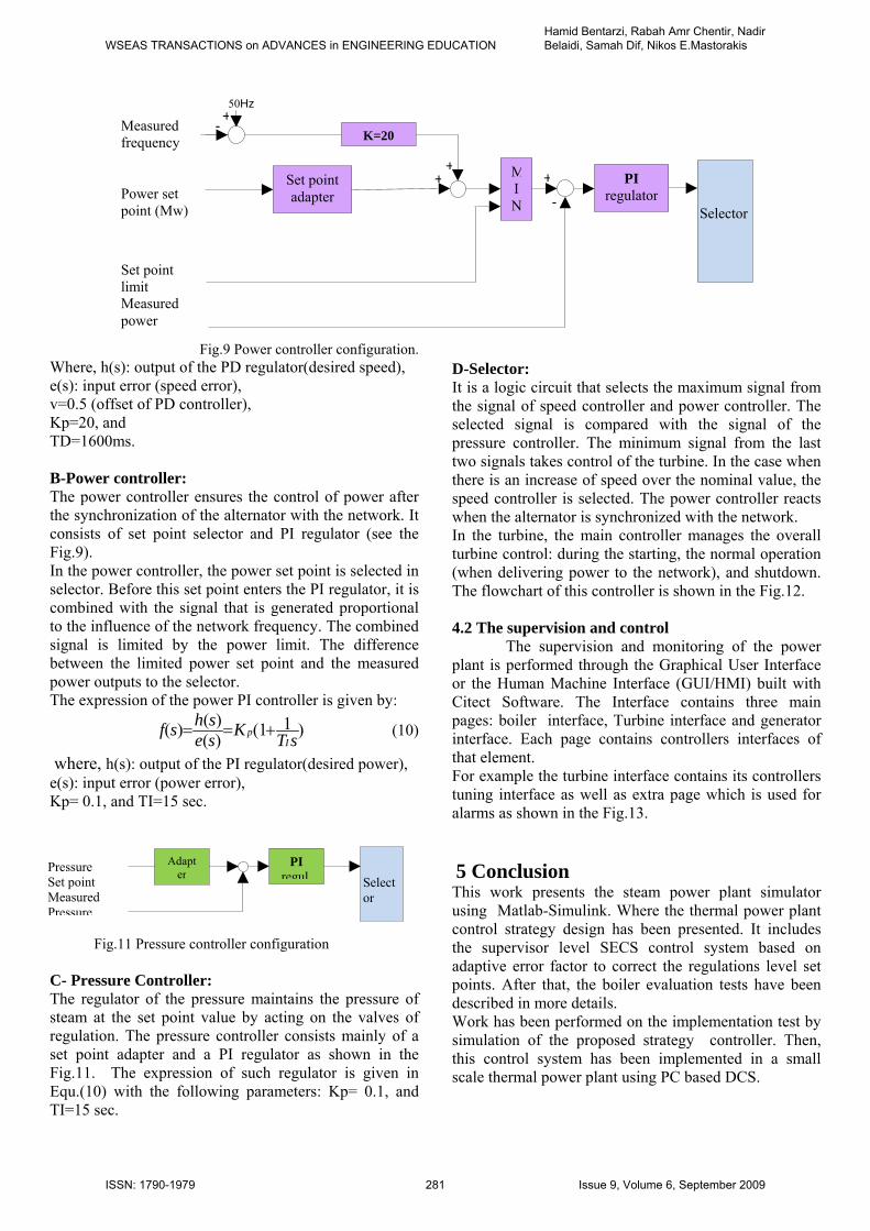
Fig.9 Power controller configuration. Where, h(s): output of the PD regulator(desired speed), e(s): input error (speed error), v=0.5 (offset of PD controller), Kp=20, and TD=1600ms. B-Power controller: The power controller ensures the control of power after the synchronization of the alternator with the network. It consists of set point selector and PI regulator (see the Fig.9). In the power controller, the power set point is selected in selector. Before this set point enters the PI regulator, it is combined with the signal that is generated proportional to the influence of the network frequency. The combined signal is limited by the power limit. The difference between the limited power set point and the measured power outputs to the selector. The expression of the power PI controller is given by:
)11()()(
)(sT
Ksesh
sfI
p (10)
where, h(s): output of the PI regulator(desired power), e(s): input error (power error), Kp= 0.1, and TI=15 sec.
Fig.11 Pressure controller configuration C- Pressure Controller: The regulator of the pressure maintains the pressure of steam at the set point value by acting on the valves of regulation. The pressure controller consists mainly of a set point adapter and a PI regulator as shown in the Fig.11. The expression of such regulator is given in Equ.(10) with the following parameters: Kp= 0.1, and TI=15 sec.
D-Selector: It is a logic circuit that selects the maximum signal from the signal of speed controller and power controller. The selected signal is compared with the signal of the pressure controller. The minimum signal from the last two signals takes control of the turbine. In the case when there is an increase of speed over the nominal value, the speed controller is selected. The power controller reacts when the alternator is synchronized with the network. In the turbine, the main controller manages the overall turbine control: during the starting, the normal operation (when delivering power to the network), and shutdown. The flowchart of this controller is shown in the Fig.12. 4.2 The supervision and control
The supervision and monitoring of the power plant is performed through the Graphical User Interface or the Human Machine Interface (GUI/HMI) built with Citect Software. The Interface contains three main pages: boiler interface, Turbine interface and generator interface. Each page contains controllers interfaces of that element. For example the turbine interface contains its controllers tuning interface as well as extra page which is used for alarms as shown in the Fig.13.
5 Conclusion This work presents the steam power plant simulator using Matlab-Simulink. Where the thermal power plant control strategy design has been presented. It includes the supervisor level SECS control system based on adaptive error factor to correct the regulations level set points. After that, the boiler evaluation tests have been described in more details. Work has been performed on the implementation test by simulation of the proposed strategy controller. Then, this control system has been implemented in a small scale thermal power plant using PC based DCS.
Set point adapter
Selector
+
-
MIN
PI regulator
+
K=20
+50Hz
+
- Measured frequency
Power set point (Mw)
Set point limit Measured power
PI regul Select
or
Pressure Set point Measured Pressure
Adapter
WSEAS TRANSACTIONS on ADVANCES in ENGINEERING EDUCATIONHamid Bentarzi, Rabah Amr Chentir, Nadir Belaidi, Samah Dif, Nikos E.Mastorakis
ISSN: 1790-1979 281 Issue 9, Volume 6, September 2009

Start
=0Hz & P=0Mw
Start electro-hydraulic Motor & Open safety valves
Speed Control (increase speed)
Stop electro-hydraulic motor
Speed Control (increase speed)
Synchronization & Speed Control
Synchronized
Speed, power, & Pressure Control
(Deliver power to the network)
Close Safety valves (Emergency Shutdown)
Speed Control (decrease speed)
Start electro-hydraulic motor
Speed Control (decrease speed)
Close safety valves
Safety valves closed
Delay
END
Stop electro-hydraulic motor
Stop
No
Yes
No
No
No
Yes
Yes
Yes
Yes
No
Yes
No
Yes
No
No
No
Yes
Yes
Fig.12 Flowchart of the turbine controller.
WSEAS TRANSACTIONS on ADVANCES in ENGINEERING EDUCATIONHamid Bentarzi, Rabah Amr Chentir, Nadir Belaidi, Samah Dif, Nikos E.Mastorakis
ISSN: 1790-1979 282 Issue 9, Volume 6, September 2009

Fig.12 HMI of the turbine Acknowledgement The authors wish to thank SONELGAZ company staff for their supports and helps and especial appreciation to Mr Hamiche AIT YALA. Nomenclature A area, m2 C specific heat, J/kgC h specific enthalpy, W/m2C Q heat flow, ppm P Power, W V volume, m3 w mass flow, ppm
Greek Letters specific density, kg/m3 DCS distributed control system FLC Fuzzy logic controller PLC programmable logic controller References: [1] R. Kumar, S. C. Kaushik and A. Kumar , Energy and Exergy Analysis of Non-reheat Thermal Power Plant, Proceedings of International Conference on Energy and Environment, P.608-611, March 19-21, 2009. [2] A. Ordys, A. Pike, M.Johnson, R. Katebi and M. Grimble, Modelling and simulation of power generation plants, Spring-Verlag, 1994. [3] H.Bentarzi, R. Amar Chentir and N. E.Mastorakis, A New Method For Controlling Boiler of Thermal power Plant Using Fuzzy Logic, Wseas Proceedings of the Europain computer onferences, Tbilisi, Georgia June 26-28, 2009. [4] M. Nakamoto, An approach of operation and control design for thermal power plants using dynamic simulation, Proc. the 2004 Int. Conf. on Control Applications, pp. 1302-130, Taipi, Taiwan, 2-4 Sep., 2004. [5] F.G. Shinskey, Process control systems : application, design and adjustment, McGraw-Hill, New York, 1977. [6] T.J. Ross, Fuzzy logic with engineering application, McGraw-Hill, Singapore, 1995. [7] R.S. Burns, Advanced control engineering, Butterworth Heinemann, Oxford, 2001.
WSEAS TRANSACTIONS on ADVANCES in ENGINEERING EDUCATIONHamid Bentarzi, Rabah Amr Chentir, Nadir Belaidi, Samah Dif, Nikos E.Mastorakis
ISSN: 1790-1979 283 Issue 9, Volume 6, September 2009

[8] David Lindsley, Power Plant Control and Instrumentation: The control of Boilers and HRSG systems, McGraw-Hill, NY, 2005 [9]M.Chidambaram, Computer control of process,
Narosa publishing house, india, 2002. [10] David Bailey, Practical SCADA for Industry,
Edwin Wright, 2003. [11] L. A. Bryan, E. A. Bryan, Programmable
Controllers: Theory and Implementation, Second Edition, 1997.
WSEAS TRANSACTIONS on ADVANCES in ENGINEERING EDUCATIONHamid Bentarzi, Rabah Amr Chentir, Nadir Belaidi, Samah Dif, Nikos E.Mastorakis
ISSN: 1790-1979 284 Issue 9, Volume 6, September 2009


![Applied Thermal Engineeringtsl.energy.hust.edu.cn/2020_Xiaohui_01.pdf · Applied Thermal Engineering journal homepage: ... heat transfer enhancement analysis, Guo et al. [34] proposed](https://img.pdfslide.net/doc/110x75/60caeeef5dbf5015477e44d3/applied-thermal-applied-thermal-engineering-journal-homepage-heat-transfer.jpg)