Embed Size (px)
Citation preview

A New Approach to Data Hiding
for Web-based Applications
by
Svetozar Ilchev
and
Zlatoliliya Ilcheva
Sofia, 2014

Copyright © 2014 by Svetozar Ilchev and Zlatoliliya Ilcheva. All Rights Reserved.


5
Table of contents
List of figures ................................................................................................ 9
List of tables ............................................................................................... 12
List of abbreviations .................................................................................. 13
Chapter 1 Introduction ............................................................................ 15
1.1 Advantages of data hiding .................................................................. 16
1.2 Data hiding in web-based scenarios ................................................... 17
1.3 Application areas ................................................................................ 19
1.4 Use Cases ........................................................................................... 20
1.4.1 Covert communication ........................................................... 20
1.4.2 Proof of Ownership ................................................................ 21
1.4.3 Multimedia Authentication ..................................................... 22
1.4.4 Fingerprinting ......................................................................... 22
1.5 Conclusion .......................................................................................... 23
Chapter 2 Important data hiding features ............................................. 25
2.1 Extensibility ........................................................................................ 25
2.2 Robustness against JPEG transformations ......................................... 25
2.3 Arbitrariness ....................................................................................... 26
Chapter 3 State-of-the-art ........................................................................ 28
3.1 Academic research ............................................................................. 29
3.2 Data hiding products and services ...................................................... 32
3.3 Conclusion .......................................................................................... 37
Chapter 4 Modular approach to data hiding ......................................... 39
Chapter 5 Extendable data hiding methods ........................................... 41
5.1 Modular design overview ................................................................... 41

6 Table of contents
5.2 Basic module resistant to JPEG transformations ................................ 44
5.2.1 Major design goals .................................................................. 44
5.2.2 Overview of the JPEG Standard ............................................. 45
5.2.3 Basic module: encoding .......................................................... 49
5.2.4 Basic module: decoding .......................................................... 52
5.2.5 Achieving robustness against JPEG transformations ............. 53
5.2.6 Conclusion .............................................................................. 56
5.3 A modular steganographic method ..................................................... 56
5.3.1 File Headers ............................................................................ 56
5.3.2 Error-correcting codes ............................................................ 57
5.3.3 Randomization ........................................................................ 59
5.3.4 Encoding ................................................................................. 61
5.3.5 Decoding ................................................................................. 62
5.3.6 Conclusion .............................................................................. 63
5.4 A modular digital watermarking method ............................................ 63
5.4.1 Headers and error-correcting codes ........................................ 64
5.4.2 Macroblocks ............................................................................ 65
5.4.3 Image modifications and watermark recovery ........................ 66
5.4.4 Encoding ................................................................................. 68
5.4.5 Decoding ................................................................................. 70
5.4.6 Conclusion .............................................................................. 71
Chapter 6 A sample .NET implementation ............................................ 72
6.1 Architectural overview ....................................................................... 72
6.2 Utilities ............................................................................................... 74
6.3 Data layer ............................................................................................ 75
6.4 Basic logic layer ................................................................................. 77
6.5 Application-specific logic layer .......................................................... 78

Table of contents 7
6.6 User interface layer............................................................................. 80
6.6.1 Standard interactive GUI ........................................................ 80
6.6.2 Batch jobs ............................................................................... 82
6.6.3 Filters and histograms ............................................................. 85
6.6.4 Web service interface ............................................................. 86
6.7 Conclusion .......................................................................................... 89
Chapter 7 Verification and evaluation ................................................... 90
7.1 Verification samples ........................................................................... 91
7.1.1 Image samples ........................................................................ 91
7.1.2 Data samples ........................................................................... 92
7.2 Verification procedures ...................................................................... 92
7.2.1 JPEG robustness verification .................................................. 93
7.2.2 Image quality verification ....................................................... 95
7.3 Verification results ............................................................................. 98
7.3.1 Modular steganographic method ............................................ 98
7.3.2 Modular digital watermarking method ................................... 99
7.4 Statistical steganalysis tests .............................................................. 100
7.5 Evaluation ......................................................................................... 101
7.6 Conclusion ........................................................................................ 105
Chapter 8 Application in web-based scenarios .................................... 107
8.1 Phishing prevention for bank portals ................................................ 107
8.1.1 Phishing overview ................................................................ 107
8.1.2 Disadvantages of traditional security technologies .............. 108
8.1.3 Data hiding for phishing prevention ..................................... 109
8.1.4 Data hiding as a certification service .................................... 110
8.1.5 Web service interface ........................................................... 113
8.1.6 Authentication information ................................................... 116
8 Table of contents
8.1.7 Integration with the bank web portal .................................... 119
8.1.8 Integration with end users’ browsers .................................... 122
8.1.9 Conclusion ............................................................................ 128
8.2 Multimedia protection for news agencies ......................................... 128
8.2.1 Problems with traditional approaches ................................... 128
8.2.2 Data hiding as enhanced multimedia protection ................... 130
8.2.3 Discovery of copyright violations ......................................... 131
8.2.4 Conclusion ............................................................................ 132
8.3 Improving the legal use of multimedia content in web-
based societies .................................................................................. 132
8.3.1 Digital watermarking for web-based communities ............... 133
8.3.2 Application scenarios ............................................................ 134
8.3.3 Conclusion ............................................................................ 137
Chapter 9 Conclusion ............................................................................. 138
9.1 Contributions .................................................................................... 138
9.1.1 Modularity and extensibility ................................................. 138
9.1.2 Improved robustness against JPEG transformations ............. 139
9.1.3 Data hiding as a certification service .................................... 139
9.2 Future work ....................................................................................... 140
References ................................................................................................ 142
9
List of figures
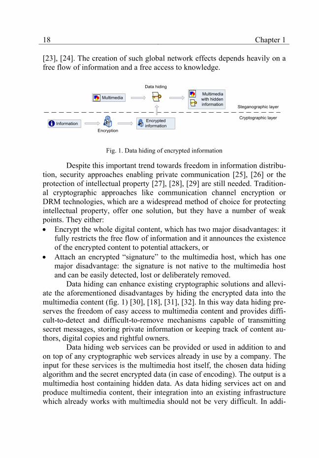
Fig. 1. Data hiding of encrypted information ....................................................................... 18
Fig. 2. Data hiding application areas .................................................................................... 19
Fig. 3. Data hiding method classification ............................................................................. 28
Fig. 4. Steganos Privacy Suite ............................................................................................. 33
Fig. 5. Invisible Secrets ........................................................................................................ 34
Fig. 6. Digimarc’s Photoshop plug-in .................................................................................. 35
Fig. 7. Photopatrol’s browser interface ................................................................................ 36
Fig. 8. SignMyImage’s standalone user interface ................................................................ 37
Fig. 9. Modular approach to data hiding in web-based scenarios ........................................ 40
Fig. 10. Basic module .......................................................................................................... 41
Fig. 11. Application-specific module ................................................................................... 42
Fig. 12. Data encoding – sequence diagram ........................................................................ 42
Fig. 13. Data decoding – sequence diagram ........................................................................ 43
Fig. 14. JPEG encoding overview ........................................................................................ 46
Fig. 15. JPEG decoding overview ........................................................................................ 48
Fig. 16. Basic module – PrepareToEncode stage ................................................................ 49
Fig. 17. DCT values – selection ........................................................................................... 50
Fig. 18. Basic module – FinishEncode stage ....................................................................... 51
Fig. 19. Basic module – decoding ........................................................................................ 52
Fig. 20. Steganographic method – file headers .................................................................... 57
Fig. 21. Error-correction encoding ....................................................................................... 58
Fig. 22. Marsaglia’s CMWC_4096 pseudo-random generator ............................................ 60
Fig. 23. Pseudo-random image block order ......................................................................... 60
Fig. 24. Steganographic method – encoding ........................................................................ 61
Fig. 25. Steganographic method – decoding ........................................................................ 62
Fig. 26. Digital watermarking method – new features ......................................................... 64
Fig. 27. Digital watermarking method – watermark headers ............................................... 64
Fig. 28. Macroblocks – structure, size and capacity ............................................................ 65
10 List of figures
Fig. 29. Image subdivision into 4 macroblocks .................................................................... 67
Fig. 30. Detection of image modifications ........................................................................... 68
Fig. 31. Digital watermarking method – encoding ............................................................... 69
Fig. 32. Digital watermarking method – decoding ............................................................... 70
Fig. 33. Implementation – architectural overview ................................................................ 73
Fig. 34. Standard interactive GUI ......................................................................................... 81
Fig. 35. GUI – program menus ............................................................................................. 81
Fig. 36. GUI – dialog window Options ................................................................................ 82
Fig. 37. GUI – batch processing control form ...................................................................... 83
Fig. 38. GUI – batch processing comparison form ............................................................... 84
Fig. 39. GUI – result of average filtering with a mask ............................................... 85
Fig. 40. GUI – histogram in the RGB color space ............................................................... 86
Fig. 41. A sample SOAP request .......................................................................................... 87
Fig. 42. A sample SOAP response ....................................................................................... 88
Fig. 43. A sample HTTP POST request ............................................................................... 88
Fig. 44. A sample HTTP POST response ............................................................................. 89
Fig. 45. Evaluation criteria ................................................................................................... 90
Fig. 46. Image samples ......................................................................................................... 91
Fig. 47. JPEG robustness verification .................................................................................. 94
Fig. 48. Image quality verification ....................................................................................... 97
Fig. 49. Modular data hiding methods – evaluation results ................................................ 104
Fig. 50. Web certificate information in the Firefox web browser ...................................... 109
Fig. 51. Data hiding as a certification service .................................................................... 111
Fig. 52. A sample SOAP request for multimedia signing .................................................. 114
Fig. 53. A sample SOAP response to the request from fig. 52 ........................................... 114
Fig. 54. A sample SOAP request for signature verification ............................................... 115
Fig. 55. A sample SOAP response to the request from fig. 54 ........................................... 115
Fig. 56. Authentication information – XSD schema .......................................................... 117
Fig. 57. Authentication information – a sample XML document ....................................... 118
Fig. 58. Manual multimedia signing – GUI ........................................................................ 120
Fig. 59. PHP code – usage of hideCopyrightInformationByImage .................................... 121
Fig. 60. User script GUI before the data hiding verification .............................................. 122

List of figures 11
Fig. 61. User script GUI after the data hiding verification ................................................. 124
Fig. 62. User script code – usage of unHideCopyrightInformationByURL........................ 125
Fig. 63. Copyright holder identification by visible text ..................................................... 129
Fig. 64. Detection of copyright violations ......................................................................... 131
Fig. 65. Micropayment for multimedia .............................................................................. 135
Fig. 66. Discovery of copyright violations ......................................................................... 136
12
List of tables
Table 1. Data hiding methods – evaluation .......................................................................... 31
Table 2. Data hiding products and services – evaluation ..................................................... 38
Table 3. Steganographic method – verification results ........................................................ 98
Table 4. Digital watermarking method – verification results ............................................... 99
Table 5. Stegdetect analysis results .................................................................................... 101
Table 6. Performance of existing data hiding methods ...................................................... 102
Table 7. Performance of existing data hiding products and services .................................. 103
13
List of abbreviations
API Application Programming Interface
ASP Active Server Pages
BMP Bitmap (image format)
CA Certification Authority
CMWC Complimentary-Multiply-With-Carry (random generator)
dB Decibel (measurement unit)
DCT Discrete Cosine Transform
DFT Discrete Wavelet Transform
DNS Domain Name System
DOM Document Object Model
DRM Digital Rights Management
DWT Discrete Wavelet Transform
ECC Error-Correcting Code
EXIF Exchangeable Image File Format
FTP File Transfer Protocol
GIF Graphics Interchange Format (image format)
GUI Graphical User Interface
HTML Hypertext Markup Language
HTTP Hypertext Transfer Protocol
ID Identification (number)
IDCT Inverse Discrete Cosine Transform
I/O Input / Output
IIS Internet Information Server
IP Internet Protocol
IT Information Technology
JFIF JPEG File Interchange Format
JPEG Joint Photographic Experts Group
LSB Least-Significant Bit

14 List of abbreviations
MPEG Moving Picture Experts Group
MSE Mean Squared Error
OOP Object-Oriented Programming
PIN Personal Identification Number
PNG Portable Network Graphics (image format)
PSNR Peak Signal-to-Noise Ratio
QIM Quantization Index Modulation
RGB Red-Green-Blue (color space)
RSA Rivest-Shamir-Adleman (encryption algorithm)
SaaS Software-as-a-Service
SOAP Simple Object Access Protocol
SSL Secure Socket Layer
TAN Transaction Authentication Number
TCP Transmission Control Protocol
TIFF Tagged Image File Format (image format)
UDP User Datagram Protocol
UML Unified Modeling Language
URL Uniform Resource Locator
XSD XML Schema Definition
XML Extensible Markup Language
YCbCr Luminance-Chrominance-Blue-Chrominance-Red (color space)

15
Chapter 1 Introduction
Data hiding is the modern name of an old science, which has its ori-gins in ancient Greece [1]. It was first known as steganography – a name composed of the Greek words “steganos” (“covered”) and “graphia” (“writ-ing”), which was first documented by the German scholar Johannes Trithemius in his work “Steganographie” [2]. Steganography was a science which focused on the theoretical methods and the practical applications of hiding secret information in various kinds of media. The hidden information had to remain transparent to the human user and normal media processing technologies. It could be read only by means of specialized transformations. Classic examples of the usage of steganography are watermarks and security metal threads hidden in banknotes [3], invisible inks [4] or the micro printing [5], which uses writing of extremely small size (< 0.5 mm) appearing as a thin line to normal human eyes.
The advance of modern communication technologies and digital mul-timedia1 has led to a renewed interest in steganography and its formation as a modern science [6]. Its name was changed to the more general term data hid-ing. At this time, data hiding encompasses two major research incentives which have gradually subdivided the science into two main sub-disciplines: the first one bears the ancient name of data hiding – steganography2 – and the second one is called digital watermarking [7], [6].
Modern steganography studies the encoding and the detection of se-cret messages transmitted and stored on digital communication platforms. Steganographic methods hide the presence of an arbitrary digital message by encoding it as part of the content of another digital media, thus making its discovery by potential investigators very difficult [8]. The importance of ste-ganography was recently reconsidered by governments with regard to terror-ist attacks [9], [10].
1 The term digital multimedia refers to text, still images, digital audio, digital video, anima-
tion or their combination. 2 From now on, when we use the term steganography, we will always refer to the sub-
discipline steganography as opposed to digital watermarking.
16 Chapter 1
Digital watermarking, on the other hand, focuses mainly on the pro-tection of intellectual property rights and the authentication of digital media [11], [12], [13]. Similar to steganographic methods, digital watermarking methods hide information in digital media. The difference consists in the purpose of the hidden information – it pertains to the digital medium itself and contains information about its author, its buyer, the integrity of the con-tent, etc. Digital watermarking methods help keeping track of the quick and inexpensive distribution of digital information over the Internet. They pro-vide new ways of ensuring the adequate protection of copyright holders in the intellectual property distribution process [14].
Data hiding methods can work on different types of multimedia – text, images, audio, video, animations, etc. The book focuses mainly on digi-tal images as the host3 medium of interest. The main reason for this focus lies in the immense popularity of images in the World Wide Web – almost every modern web portal uses them to enhance its presentation to end users. The obtained results can be easily generalized for video streams, as well, be-cause most video formats encode their key frames in digital image formats.
In the next sections of the introduction, the advantages of data hiding technologies over traditional security approaches are illustrated, the use of data hiding in web-based scenarios is motivated, some web-related applica-tion areas of data hiding are discussed and several important use cases are presented.
1.1 Advantages of data hiding
The tasks of both data hiding sub-disciplines: steganography (covert communication) and digital watermarking (intellectual property protection and digital multimedia authentication) fall traditionally within the applica-tion area of cryptography. Cryptographic approaches can make communica-tion channels unreadable by third-parties. They can guarantee the integrity and the origin of encrypted digital media as well as their readability only by a chosen recipient (for an overview of cryptography, please refer to [15]). They are based on solid theoretical mathematical foundations [16]. Examples include the Secure Socket Layer (SSL) communication to bank web portals or Digital Rights Management (DRM) technologies for the protection of in-tellectual property [17], [18].
3 The term host refers to any digital media, in which steganographic and digital watermark-
ing methods hide information.

Introduction 17
With regard to multimedia content, data hiding can offer specialized solutions, which have the following distinct technological and legal ad-vantages over general cryptographic approaches: Flexibility: data hiding methods can be designed to withstand common
transformations of the digital medium such as different levels of lossy compression, cropping, scaling, rotation, etc. This is especially important for digital watermarking because the protected intellectual property often undergoes such intentional or unintentional changes. DRM schemes do not allow any transformations of the protected content and thus restrict unnecessarily the legal usage of the multimedia content.
Transparency: data hiding technologies are generally transparent to the end user. These technologies are detectable only by specialized software developed specifically for this purpose. Cryptographic approaches, on the other hand, are easily detectable by the end user.
Self-sufficiency: as data hiding methods embed their information into the multimedia stream, any transmission of signatures, cryptographic hashes, etc. is not necessary.
Reliability: the steganographic or digital watermarking information be-comes part of the multimedia itself and (without knowledge of the meth-ods in use) cannot be removed by third parties without destroying a sig-nificant part of the multimedia content. Cryptographic information, on the other hand, is easy to remove from multimedia once the multimedia has been decrypted.
Absence of legal regulations: both steganography and digital water-marking are unburdened by legal regulations applicable to traditional cryptography [19].
In order to make use of these advantages, the author of the multime-dia content should be willing to sacrifice the access restrictions implemented by DRM schemes. Steganography and watermarking cannot reliably block the end user’s access to the host medium and assume that anyone can view its content.
1.2 Data hiding in web-based scenarios
A major design goal of the World Wide Web is to provide universal-ly available means for human communication, commerce, and opportunities to share knowledge [20]. The number of its users amounted to almost 1.6 Milliard in 2008 [21], which emphasizes its significance as an information sharing medium. Tim O’Reilly summarizes that: “Network effects from user contributions are the key to market dominance in the Web 2.0 era” [22],
18 Chapter 1
[23], [24]. The creation of such global network effects depends heavily on a free flow of information and a free access to knowledge.
Encryptedinformation
Multimedia Multimedia
with hidden information
InformationEncryption
Data hiding
Steganographic layer
Cryptographic layer
Fig. 1. Data hiding of encrypted information
Despite this important trend towards freedom in information distribu-tion, security approaches enabling private communication [25], [26] or the protection of intellectual property [27], [28], [29] are still needed. Tradition-al cryptographic approaches like communication channel encryption or DRM technologies, which are a widespread method of choice for protecting intellectual property, offer one solution, but they have a number of weak points. They either: Encrypt the whole digital content, which has two major disadvantages: it
fully restricts the free flow of information and it announces the existence of the encrypted content to potential attackers, or
Attach an encrypted “signature” to the multimedia host, which has one major disadvantage: the signature is not native to the multimedia host and can be easily detected, lost or deliberately removed.
Data hiding can enhance existing cryptographic solutions and allevi-ate the aforementioned disadvantages by hiding the encrypted data into the multimedia content (fig. 1) [30], [18], [31], [32]. In this way data hiding pre-serves the freedom of easy access to multimedia content and provides diffi-cult-to-detect and difficult-to-remove mechanisms capable of transmitting secret messages, storing private information or keeping track of content au-thors, digital copies and rightful owners.
Data hiding web services can be provided or used in addition to and on top of any cryptographic web services already in use by a company. The input for these services is the multimedia host itself, the chosen data hiding algorithm and the secret encrypted data (in case of encoding). The output is a multimedia host containing hidden data. As data hiding services act on and produce multimedia content, their integration into an existing infrastructure which already works with multimedia should not be very difficult. In addi-
Introduction 19
tion, they (unlike cryptography) ensure backwards compatibility with sys-tems which do not consider security issues.
1.3 Application areas
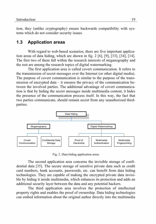
With regard to web-based scenarios, there are five important applica-tion areas of data hiding, which are shown in fig. 2 [6], [9], [33], [34], [14]. The first two of them fall within the research interests of steganography and the rest are among the research topics of digital watermarking.
The first application area is called covert communication. It refers to the transmission of secret messages over the Internet (or other digital media). The purpose of covert communication is similar to the purpose of the trans-mission of encrypted data – it ensures the privacy of the communication be-tween the involved parties. The additional advantage of covert communica-tion is that by hiding the secret messages inside multimedia content, it hides the presence of the communication process itself. In this way, the fact that two parties communicate, should remain secret from any unauthorized third-parties.
Data Hiding
Steganography
Digital Watermarking
Covert Communication
Confidential Data Storage
Proof of Ownership
Multimedia Authentication
Multimedia Fingerprinting
Fig. 2. Data hiding application areas
The second application area concerns the invisible storage of confi-dential data [35]. The secure storage of sensitive private data such as credit card numbers, bank accounts, passwords, etc. can benefit from data hiding technologies. They are capable of making the encrypted private data invisi-ble by hiding it inside multimedia, which enhances its protection and adds an additional security layer between the data and any potential hackers.
The third application area involves the protection of intellectual property rights and enables the proof of ownership. Data hiding technologies can embed information about the original author directly into the multimedia

20 Chapter 1
content. In this way, when arguments concerning the ownership of the mul-timedia arise, the legitimate author can prove its ownership claim.
The fourth application area – multimedia authentication – refers to the protection of multimedia content against unauthorized changes. By means of data hiding technologies the exact areas inside the multimedia con-tent, which have been modified without authorization, can be detected and the changes can be even reversed [36].
The fifth application area – multimedia fingerprinting – also concerns the protection of intellectual property rights. In close similarity to the proof of ownership application, data hiding methods embed information about the buyer or the legitimate user of the multimedia content. In this way, if actions violating the rights of the copyright holder are undertaken – such as the ille-gal distribution of the multimedia content over the Internet – the perpetrator can be identified by means of the secret information embedded in the dis-tributed copies.
The five data hiding application areas presented above enumerate on-ly the most important and widespread web-relevant uses of data hiding. The World Wide Web is a highly dynamic field and the list may be easily ex-panded by new data hiding application areas with each major advance of modern information and communication technologies.
1.4 Use Cases
In order to illustrate some of the applications of data hiding (for a more detailed discussion see [6], chapter 2), one use case describing an ap-plication of steganography and three use cases considering digital water-marking are presented. They show the practical benefits of both technologies in comparison with traditional cryptographic approaches as well as the pos-sibilities for flexible integration into modern web-supported processes of communication and distribution of intellectual property.
1.4.1 Covert communication
This use case discusses the merger of two joint-stock companies. Such a merger typically has a large impact on financial markets and the companies try to keep it secret. They need to communicate with each other in order to negotiate the terms of the merger but even the presence of an in-creased amount of communication between the two companies could serve as an indication of the merger to financial speculators. The Internet is inher-

Introduction 21
ently insecure and the companies are not sure who monitors their communi-cations and for what purpose.
Traditional cryptographic approaches are not helpful in this situation because they cannot conceal the fact, that substantial amount of communica-tion takes place between the two firms. On the basis of this communication and the economic situation, the pending merger can be easily inferred.
Steganography can conceal the existence of the communication pro-cess itself by transmitting the correspondence inside non-conspicuous graph-ic images or photos. Both companies can use their company forums, public services for storing images like Flickr, knowledge sharing platforms like Wikipedia or communication platforms like Facebook to exchange the mul-timedia hosts.
The encoding and decoding of the secret messages may be imple-mented as an extension of the corporate IT infrastructure or by adding addi-tional web services responsible for the handling of the secret messages.
1.4.2 Proof of Ownership
This use case discusses a news agency NA, which publishes a news portal on the Internet. A competitor news agency NB downloads the photos accompanying the news articles from the web portal of NA and uses them in the editions of its own online newspaper. NA would like to prove that it is the legal owner of the photos and expose the actions of NB as copyright viola-tions. As any digital data related to photos can be easily falsified, NA’s suc-cess is uncertain.
Traditional cryptographic DRM approaches cannot prevent the mis-appropriation of intellectual property or help proving the ownership of the photos if they have been made publicly available on the Internet. Digital wa-termarking, on the other hand, can encode information about the real author into the photos. News agency NA can subscribe to such a watermarking ser-vice provided by the company DiWa specialized in digital watermarking. It has to make a small modification to the software of its web server, so that any photos being uploads to the server are automatically sent to DiWa for watermarking before being published on the web site.
Due to the advantages of flexibility, self-sufficiency and reliability discussed in section 1.1, the hidden information will be very probably pre-sent in the copies of the photos which have been published in the online newspaper of new agency NB. The transparency advantage makes it proba-

22 Chapter 1
ble that NB does not even suspect the existence of the hidden watermark4. When the issue of copyright infringement is brought up, DiWa can confirm that news agency NA is the real copyright holder by means of the embedded watermark.
1.4.3 Multimedia Authentication
This use case discusses a company which is responsible for the im-plementation of a network of security cameras in a factory. They are con-nected to the Internet and automatically archive all images to a central serv-er. One day a box containing a new prototype is found missing from one of the production areas. The camera records show how trespassers have broken into the facility. They have also recorded the face of one of the workers. He claims to be innocent.
In order to be sure that the camera records are reliable evidence, the company needs means to verify that they have not been tampered with. This can be done by means of cryptographic approaches [37] but digital water-marking can offer the useful advantage of detecting which parts of the cam-era records have been modified. This is achieved by encoding a special sig-nature called a fragile watermark5 into the records which becomes broken in the modified parts. Furthermore, there are specialized digital watermarking methods that allow the recovering of the original modified parts [36].
In this use case, digital watermarking can confirm that the area of the camera records showing the face of the worker has been tampered with. It may be even able to recover the face of the actual perpetrator. This leads to the conclusion that the worker is innocent. A other information regarding how the theft has been carried out is genuine and can be relied upon in the course of investigation.
1.4.4 Fingerprinting
This use case has been inspired by a real story recently encountered on the Internet [38].
An artist creates expensive digital drawings (intellectual property). He or she has an agent who takes over the distribution of the drawings to
4 The term watermark (in the context of digital watermarking) refers to any hidden infor-
mation in a digital medium which pertains to this medium and identifies its owner, buyer, proves its integrity, etc.
5 The term fragile watermark refers to a watermark which is broken if the host medium is modified.
Introduction 23
galleries and their sale to individual customers. The artist uploads the new works to the agent’s server and then receives notifications from the agent about the sales process. One day the artist finds some of the new drawings on the Internet despite legal contractual regulations prohibiting galleries and individual end-buyers from distribution. He or she would like to prevent fur-ther incidents and sue the contract violator for damages.
Traditional cryptographic DRM approaches are not helpful in this situation. They cannot reliably prevent the sharing of the drawings or identi-fy the culprit. Any authorized gallery or end-buyer can view a drawing en-crypted by DRM, which means that they can reproduce the drawing and put it on the Internet without leaving a trace to their identity.
Digital watermarking offers a working solution. It cannot enforce the prevention of the distribution of the drawings but it offers a means of identi-fying the contract violator by fingerprinting each legally distributed copy of the drawing with information about its initial buyer.
In order to implement this solution, the artist’s agent subscribes to a fingerprinting web service provided by the company DiWa specialized in digital watermarking. The service needs an image and a buyer identification string as input and delivers a watermarked image as output. The agent needs only a minor modification of his systems: instead of sending drawings di-rectly to a gallery or an end-buyer, the systems first send the drawings to-gether with the name of the buyer to the fingerprinting service and only then forward the resulting image to the corresponding gallery or end-buyer.
If an illegally distributed copy is found on the Internet, the ad-vantages of flexibility, self-sufficiency and reliability of digital watermark-ing technologies described in section 1.1 make it very probable that any in-formation about the initial buyer encoded in the drawing by the DiWa web service is still present in the copy. The information can then be extracted by another web service provided by DiWa and the contract violator can be sued for damages.
1.5 Conclusion
Data hiding technologies embed information into multimedia. They are explicitly developed for this purpose and this specialization makes them the most suitable technology for multimedia-related protection. They have the potential to improve the overall security in the World Wide Web and to assist in the protection of intellectual property rights.
The presented use cases show some typical application areas of data hiding and give first ideas how the technology can be used in practical web-

24 Chapter 1
related scenarios. Chapter 8 elaborates on these ideas and presents the de-tailed integration of data hiding in two concrete web-based scenarios. These examples show how data hiding can be brought close to end users and used for their protection. The process is straightforward and the benefits are clear, which forms a sufficient motivation for the strong academic and corporate interest in data hiding technologies.
25
Chapter 2 Important data hiding features
Data hiding methods may implement a number of different features such as robustness against geometric transformations, format changes, re-placement of parts of the multimedia host, etc. [39], [40]. With regard to web-based scenarios, three features are especially important: extensibility, robustness against JPEG transformations and arbitrariness of the image host and the hidden data.
2.1 Extensibility
The inherent openness and volatility of the World Wide Web in combination with the rapid changes in the contemporary social, business and technological environment lead to frequent modifications in user require-ments. Some of them pertain to the application areas of data hiding technol-ogy. For this reason, data hiding methods should be adaptable to new user requirements and they should be capable of incorporating new features, while still providing certain basic functionality expected by the end user.
In order to achieve extensibility, there are two important considera-tions: A modular design approach is needed because monolithic solutions are
not flexible and cannot be modified in accord with the frequent changes in the modern web.
A well-established and standardized technology for interconnection is needed. It will enable the incorporation of data hiding technologies into an existing infrastructure and it will provide a flexible integration with other technologies like cryptography, compression, etc.
Both considerations make a global common approach (as opposed to specialized solutions) towards data hiding important.
2.2 Robustness against JPEG transformations
A typical requirement for data hiding methods is that they ensure the preservation of the information embedded into the multimedia host after

26 Chapter 2
compression [6], [14]. It is related to the advantage of flexibility introduced in section 1.1.
Compression is applied to reduce the size of the transmitted multi-media content and most often lossy compression formats are utilized due to their higher compression ratio. One of the most important compressed image formats is JPEG, which utilizes the discrete cosine transform (DCT) [41]. Its universality and good compression ratio have made it a preferred choice for storing color images. For this reason, it is important for hidden data not to be destroyed by JPEG transformations.
There are three basic types of transformations: compression – encodes a matrix of pixels6 in a JPEG image file; decompression – decodes a matrix of pixels from a JPEG image file; recompression – changes the compression ratio (or other parameters) of a
JPEG image file. The robustness against all three transformation types is important for
the flexible use of data hiding algorithms in web. Compression is used to re-duce the size of newly created images and to make them readable by brows-ers. Decompression is used to extract the image content, so that it can be shown on screen, modified or recoded in another image format. Recompres-sion is used mainly to reduce the image size. It is often applied to existing JPEG images prior to their distribution via web-related channels (sending by e-mail or uploading to a web site).
It is important to achieve robustness against the execution of the transformations by arbitrary programs. For this purpose, intimate knowledge of the JPEG image compression standard itself is needed as JPEG is an open format allowing much freedom in its specific implementations by software vendors [41], [42]. Two of the most important benefits are the minimization of the host image distortions and the achievement of a higher degree of ro-bustness.
2.3 Arbitrariness
Image content is widely used on the web in different forms. Data hid-ing methods need to be flexible enough to cope with arbitrary host images supplied by users. This requirement has two important implications:
6 Every digital image must be represented by a rectangular matrix of pixels prior to JPEG
compression.
Important data hiding features 27
1. Data hiding methods should be able to handle black-and-white, greyscale and color images and they should not be dependent on any characteris-tics, which are specific for a particular class of images.
2. The original image or any statistical information describing it should not be necessary for the decoding of the embedded information. Data hiding methods having this property are referred to as “blind” and provide max-imum flexibility [6].
As data hiding methods in web often work on encrypted or com-pressed user-defined data, they should not impose any restrictions on the form or the future use of the hidden data. Two considerations are important: 1. The embedded data should be regarded as an arbitrary stream of binary
data. 2. An error-free retrieval of the embedded data should be possible in order
to permit its subsequent use by other technologies. The arbitrariness of the image host and the embedded data facilitates
the adaptability of data hiding methods to changing user requirements as the methods can work on a wide variety of image hosts or embedded data. In addition, this feature enhances their extensibility (see section 2.1).

28
Chapter 3 State-of-the-art
This chapter presents a brief state-of-the-art review of data hiding. Both academic research and practical data hiding implementations are con-sidered and their suitability for web-related applications is discussed. A clas-sification of the most important types of data hiding methods is presented in fig. 3 [7], [40], [43], [14], [34].
Data hiding methods
Spatial domain methods
Transform domain methods
Least-significant bit (LSB) methods
Discrete fourier transform (DFT) methods
Discrete cosine transform (DCT) methods
Discrete wavelet transform (DWT) methods
DCT methods not based on JPEG specification details
DCT methods considering JPEG specification details
Fig. 3. Data hiding method classification
Spatial domain methods work directly on image pixels. Most often they fall into the group of the so called least-significant bit (LSB) methods, which modify the LSBs of image pixels. Transform domain methods, on the other hand, work on the output of various mathematical transforms of the image. As lossy image compression is often based on such mathematical transforms, these methods perform well if the hidden information has to withstand image compression. Three widely used transforms are the discrete Fourier transform (DFT), the discrete cosine transform (DCT) and the dis-crete wavelet transform (DWT). DCT data hiding methods are based on the same mathematical transform used by the JPEG standard [41]. They can be further divided into two groups: DCT methods which are not based on the

State-of-the-art 29
JPEG specification and DCT methods which follow JPEG specification de-tails as described in the standard and its most popular implementations.
Due to the large number of existing data hiding methods and the im-portance of the JPEG image format, only DCT methods are reviewed. Their capability of handling JPEG transformations (feature 2.2) is examined and, as discussed in section 2.2, the group of DCT methods considering the JPEG specification details is of special importance. Further, the conformity to fea-tures 2.1 and 2.3 is evaluated.
3.1 Academic research
The first JPEG-based data hiding method was JSTEG, developed in 1993 by Derek Upham [44], [45], [46], [47]. It is a steganographic method which hides arbitrary binary data by replacing the LSBs of the DCT coeffi-cients of JPEG images. Another early data hiding method for digital water-marking was proposed by Zhao and Koch, Fraunhofer institute, Darmstadt in 1995 [48], [49]. It hides one bit per DCT block by creating a special relation-ship among the elements of a set of three DCT coefficients. O’Ruanaidh, et. al., Geneva University, suggested in 1996 a method for robust bi-directional encoding of digital watermarks into DCT coefficients [50]. The method is not blind but it can work on arbitrary watermark data. None of the three methods discusses JPEG decompression or recompression.
Another digital watermarking method was developed in 1997 by Cox, et al., University College London [51]. The method hides watermarks drawn from a Gaussian normal distribution into DCT coefficients by means of scaling functions. The algorithm is very robust but it is not blind and can-not work with arbitrary hidden data. In 1998, Wu and Liu, Princeton Univer-sity, developed another method for digital watermarking [52]. The method hides a “visually meaningful binary pattern” together with some image con-tent features into the quantized DCT coefficients by means of a specialized look-up table. JPEG decompression or JPEG recompression are not consid-ered.
Lin and Chang, Columbia University, introduced in 2000 a method for digital watermarking, which aims at detecting and partially recovering changed parts of images by using specialized watermarks containing rough approximations of the original image [53], [54], [55]. The method is de-signed to be robust against JPEG recompression but the authors discuss in [54] some false alarms due to noise caused by compression and decompres-sion during JPEG transformations.
30 Chapter 3
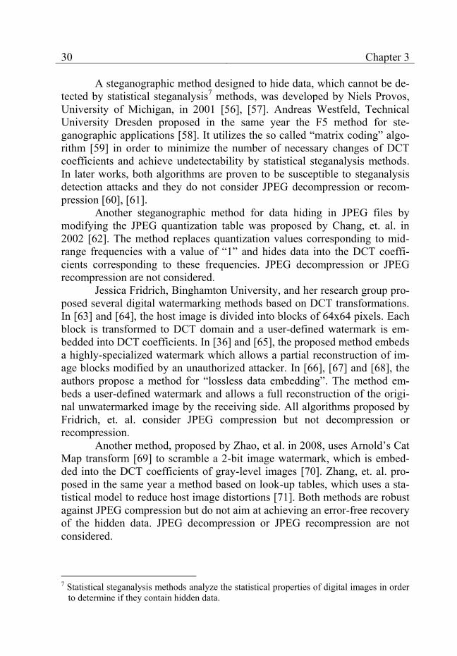
A steganographic method designed to hide data, which cannot be de-tected by statistical steganalysis7 methods, was developed by Niels Provos, University of Michigan, in 2001 [56], [57]. Andreas Westfeld, Technical University Dresden proposed in the same year the F5 method for ste-ganographic applications [58]. It utilizes the so called “matrix coding” algo-rithm [59] in order to minimize the number of necessary changes of DCT coefficients and achieve undetectability by statistical steganalysis methods. In later works, both algorithms are proven to be susceptible to steganalysis detection attacks and they do not consider JPEG decompression or recom-pression [60], [61].
Another steganographic method for data hiding in JPEG files by modifying the JPEG quantization table was proposed by Chang, et. al. in 2002 [62]. The method replaces quantization values corresponding to mid-range frequencies with a value of “1” and hides data into the DCT coeffi-cients corresponding to these frequencies. JPEG decompression or JPEG recompression are not considered.
Jessica Fridrich, Binghamton University, and her research group pro-posed several digital watermarking methods based on DCT transformations. In [63] and [64], the host image is divided into blocks of 64x64 pixels. Each block is transformed to DCT domain and a user-defined watermark is em-bedded into DCT coefficients. In [36] and [65], the proposed method embeds a highly-specialized watermark which allows a partial reconstruction of im-age blocks modified by an unauthorized attacker. In [66], [67] and [68], the authors propose a method for “lossless data embedding”. The method em-beds a user-defined watermark and allows a full reconstruction of the origi-nal unwatermarked image by the receiving side. All algorithms proposed by Fridrich, et. al. consider JPEG compression but not decompression or recompression.
Another method, proposed by Zhao, et al. in 2008, uses Arnold’s Cat Map transform [69] to scramble a 2-bit image watermark, which is embed-ded into the DCT coefficients of gray-level images [70]. Zhang, et. al. pro-posed in the same year a method based on look-up tables, which uses a sta-tistical model to reduce host image distortions [71]. Both methods are robust against JPEG compression but do not aim at achieving an error-free recovery of the hidden data. JPEG decompression or JPEG recompression are not considered.
7 Statistical steganalysis methods analyze the statistical properties of digital images in order
to determine if they contain hidden data.
State-of-the-art 31
Table 1. Data hiding methods – evaluation
Method Exten-sibility
Robustness against JPEG transformations Arbitrariness
Com-pres-sion
Decom-pression
Recompres-sion
Arbi-trary host
Blind meth-
od
Arbi-trary data
Error-free re-trieval
JSteg [44], [46] no yes N.C.* N.C. yes yes yes yes
Zhao, Koch [48], [49] no yes N.C. N.C. yes yes yes yes
O’Ruanaidh, et. al. [50] no yes N.C. N.C. yes no yes yes
Cox, et. al. [51] no yes yes yes yes no no no
Wu, Liu [52] no yes N.C. N.C. yes yes no yes
Lin, Chang [53], [54],
[55] no yes yes yes yes yes no partial
Provos [56], [57] no yes N.C. N.C. yes yes yes yes
Westfeld [58] no yes N.C. N.C. yes yes yes yes
Chang, et. al. [62] no yes N.C. N.C. yes yes yes yes
Fridrich [63], [64] no yes N.C. N.C. yes yes yes no
Fridrich [36], [65] no yes N.C. N.C. yes yes no yes
Fridrich [66], [67],
[68] no yes N.C. N.C. yes yes yes yes
Zhao, et. al. [70] no yes N.C. N.C. yes yes no no
Zhang, et. al. [71] no yes N.C. N.C. yes yes yes no
Li, Cox [72] no yes N.C. N.C. yes yes yes no Sun, et. al.
[73] no yes N.C. N.C. yes yes yes no
Izadinia, et. al. [74] no yes N.C. N.C. yes yes yes yes
* N.C. = Not Considered Some recent data hiding algorithms rely on a technique called Quan-
tization Index Modulation (QIM), which was first introduced by Costa in 1983 [75] and later analyzed with regard to watermarking applications by Chen and Wornell in 2001 [76]. Li and Cox proposed in 2007 a watermark-ing method based on QIM and a perceptual model developed by Watson [72], [77]. An improved version of the method was developed in 2008 by
32 Chapter 3
Sun, et. al [73]. Both methods are designed to be robust against changes of the image brightness, but an error-free retrieval of the embedded watermark after JPEG compression is not possible.
Another steganographic method utilizing QIM was proposed by Iza-dinia, et. al. in 2009 [74]. It hides an arbitrary message by applying an algo-rithm for predictive coding (proposed by Yu, et. al. [78]) to quantized DCT coefficients. JPEG decompression or JPEG recompression are not consid-ered.
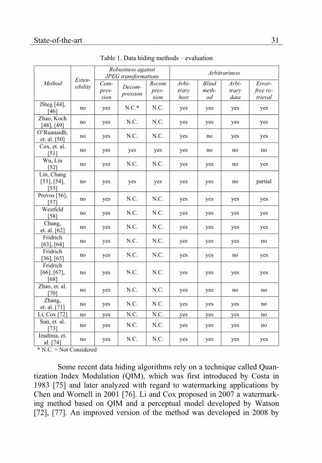
A brief evaluation of all methods with regard to features 2.1, 2.2 and 2.3 is presented on table 1 (N.C. stands for “Not Considered”).
None of the presented methods considers extensibility (feature 2.1). They are monolithic solutions designed for concrete application areas with specific feature requirements. The authors do not discuss how the methods could be integrated into existing solutions.
The robustness against JPEG transformations (feature 2.2) and the arbitrariness of the host image and the embedded data (feature 2.3) are taken into account only partially. Most methods consider only certain aspects of them (presented on table 1). The potential for improvement lies in the simul-taneous implementation of all relevant aspects of the features.
3.2 Data hiding products and services
In accordance with the strong academic and corporate interest in data hiding, there are some popular data hiding products and services offered over the Internet or as part of larger software bundles.
One of the most well-known steganographic solutions on the market is the Steganos Privacy Suite [79] (fig. 4). The File Manager tool can embed data into compressed or uncompressed host images. The hidden information is robust against JPEG compression at low compression rates but not against JPEG decompression or recompression. The steganographic method is blind and can work with arbitrary data files and host images. A major advantage is the excellent image quality.
A classic steganographic program for embedding arbitrary data files into JPEG images is JPHide [80]. Its steganographic method is robust against JPEG compression at low compression ratios but not against JPEG decom-pression or recompression. The method is blind and can work with arbitrary JPEG host images. It also delivers excellent image quality.
A new steganographic development is the InvisibleSecrets stand-alone GUI program [81] (currently version 4). It has a very nice user inter-face (fig. 5) and supports compressed and uncompressed image formats.

State-of-the-art 33
With regard to JPEG, it hides the information in the JPEG comment seg-ments (see [41]). This approach has the advantage of not placing any limits to the size of the embedded data but negates many of the advantages of data hiding described in section 1.1. The method can work with arbitrary data and it is robust against JPEG compression and recompression but not against JPEG decompression.
Fig. 4. Steganos Privacy Suite
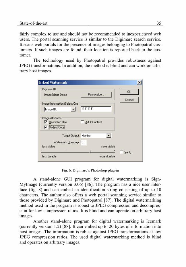
Digimarc [82] is one of the leading data hiding specialists that spe-cializes in digital watermarking. The Photoshop plug-in (fig. 6) which signs digital images is the company’s most well-known product.
The plug-in embeds a short identification number (ID) along with three Boolean image attributes into the digital content. The identification number plays a central role in the solutions offered by Digimarc – the Digimarc search service, which scans the Internet for images containing the client’s ID number, and the integration with digital asset and content man-agement systems targeted at enterprise users.
The Digimarc search service [83] scans web portals for digital imag-es belonging to Digimarc customers. First, it parses the web portals for im-ages. Then, it tries to read a previously embedded ID number out of each im-

34 Chapter 3
age. If the ID number exists and matches a current customer of the search service, then the location of the image is reported to this customer. In this way, the search service helps customers to keep track of the locations where their digital images are published online.
Fig. 5. Invisible Secrets
The digital watermarking method used by Digimarc is fairly robust against JPEG compression, decompression and recompression. The end user has the flexibility of changing the trade-off between robustness and image quality (discussed in detail in chapter 7) via the slider at the bottom of the plug-in window (fig. 6). In addition, the method is blind and works with ar-bitrary host images.
Another digital watermarking service provider is Photopatrol [84] (fig. 7), which uses a digital watermarking technology developed by Fraun-hofer Institute SIT, Darmstadt [85].
Photopatrol provides two major online services – a service for sign-ing digital images and a service for scanning images on predefined web por-tals for the presence of embedded signatures. The image signing service re-lies on a combination of modern browser technologies and Java applets. It is
State-of-the-art 35
fairly complex to use and should not be recommended to inexperienced web users. The portal scanning service is similar to the Digimarc search service. It scans web portals for the presence of images belonging to Photopatrol cus-tomers. If such images are found, their location is reported back to the cus-tomer.
The technology used by Photopatrol provides robustness against JPEG transformations. In addition, the method is blind and can work on arbi-trary host images.
Fig. 6. Digimarc’s Photoshop plug-in
A stand-alone GUI program for digital watermarking is Sign-MyImage (currently version 3.06) [86]. The program has a nice user inter-face (fig. 8) and can embed an identification string consisting of up to 10 characters. The author also offers a web portal scanning service similar to those provided by Digimarc and Photopatrol [87]. The digital watermarking method used in the program is robust to JPEG compression and decompres-sion for low compression ratios. It is blind and can operate on arbitrary host images.
Another stand-alone program for digital watermarking is Icemark (currently version 1.2) [88]. It can embed up to 20 bytes of information into host images. The information is robust against JPEG transformations at low JPEG compression ratios. The used digital watermarking method is blind and operates on arbitrary images.

36 Chapter 3
Fig. 7. Photopatrol’s browser interface
Another alternative is the stand-alone GUI program Eikonamark (currently version 4.8) [89]. The program can embed up to 8 bytes into arbi-trary host images. The hidden information is robust against JPEG compres-sion but not against decompression or recompression. The digital watermark-ing method is blind. The authors also offer a crawling engine for scanning web portals for images containing embedded signatures [90] .
A new set of solutions in the digital watermarking field is offered by the Singapore company DataMark [91]. The main product of the company is the StegMark SDK which provides a set of digital watermarking libraries for popular programming languages. They can be used by clients to provide dig-ital watermarking functionality in their own software solutions.
The conformity of the presented products and services to features 2.1, 2.2 and 2.3 is presented on table 2 (N.C. stands for “Not Considered”). Due to some restrictions, the DataMark digital watermarking methods are not part of the review.

State-of-the-art 37
The differences between the steganographic and the digital water-marking solutions can be clearly seen. The steganographic solutions can work with arbitrary host images and data (feature 2.3) but they are not as ro-bust against JPEG transformations (feature 2.2) as the reviewed digital wa-termarking solutions. The digital watermarking solutions, on the other hand, can embed only several small predefined data types – most often ID num-bers.
Fig. 8. SignMyImage’s standalone user interface
None of the existing solutions considers extensibility (feature 2.1). The solutions are monolithic and cannot be adapted to user requirements, which require changes in the provided method features.
3.3 Conclusion
All solutions offer their own set of predefined method features, which have to be accepted by end customers. As shown in chapter 7, there is a trade-off between the image quality, the amount of embeddable data and the provided method features. Any method features which are not needed should not be implemented in order to achieve a more attractive trade-off for the end user. In this case, the monolithic approach, which hinders this kind
38 Chapter 3
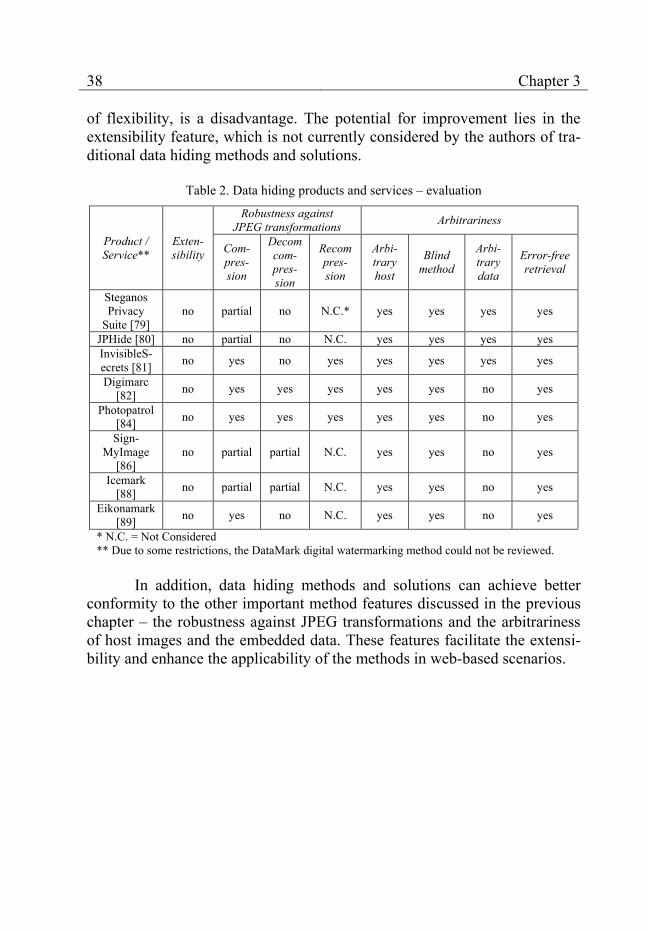
of flexibility, is a disadvantage. The potential for improvement lies in the extensibility feature, which is not currently considered by the authors of tra-ditional data hiding methods and solutions.
Table 2. Data hiding products and services – evaluation
Product / Service**
Exten-sibility
Robustness against JPEG transformations Arbitrariness
Com-pres-sion
Decomcom-pres-sion
Recompres-sion
Arbi-trary host
Blind method
Arbi-trary data
Error-free retrieval
Steganos Privacy
Suite [79] no partial no N.C.* yes yes yes yes
JPHide [80] no partial no N.C. yes yes yes yes InvisibleS-ecrets [81] no yes no yes yes yes yes yes
Digimarc [82] no yes yes yes yes yes no yes
Photopatrol [84] no yes yes yes yes yes no yes
Sign-MyImage
[86] no partial partial N.C. yes yes no yes
Icemark [88] no partial partial N.C. yes yes no yes
Eikonamark [89] no yes no N.C. yes yes no yes
* N.C. = Not Considered ** Due to some restrictions, the DataMark digital watermarking method could not be reviewed.
In addition, data hiding methods and solutions can achieve better
conformity to the other important method features discussed in the previous chapter – the robustness against JPEG transformations and the arbitrariness of host images and the embedded data. These features facilitate the extensi-bility and enhance the applicability of the methods in web-based scenarios.
39
Chapter 4 Modular approach to data hiding
Considering the discussions in the previous chapters, the following drawbacks of existing data hiding methods based on DCT can be identified: 1. Current steganographic methods are monolithic and cannot be adapted
to changes of user requirements (feature 2.1). 2. Very few methods are designed to be robust against JPEG decompres-
sion or recompression (feature 2.2) and they do not fully conform to fea-ture 2.3.
3. Features 2.2 and 2.3 are implemented differently by each of the present-ed methods. Each method has a different degree of robustness against JPEG transformations and various restrictions on the arbitrariness of the image host and the hidden data. Therefore, if a company has to use sev-eral data hiding methods for several corresponding application areas, it has to consider these differences explicitly.
4. It is unclear how existing methods can be integrated into existing solu-tions (feature 2.1).
In this book a new modular approach to data hiding in web-based scenarios will be discussed, designed and implemented. The modular ap-proach will address and try to overcome each one of the drawbacks present-ed above. In accordance with these considerations, our main objectives are as follows: 1. Enable the development of extendable data hiding methods. Each meth-
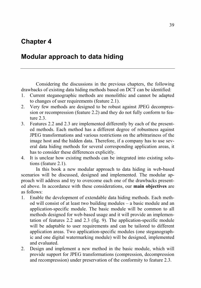
od will consist of at least two building modules – a basic module and an application-specific module. The basic module will be common to all methods designed for web-based usage and it will provide an implemen-tation of features 2.2 and 2.3 (fig. 9). The application-specific module will be adaptable to user requirements and can be tailored to different application areas. Two application-specific modules (one steganograph-ic and one digital watermarking module) will be designed, implemented and evaluated.
2. Design and implement a new method in the basic module, which will provide support for JPEG transformations (compression, decompression and recompression) under preservation of the conformity to feature 2.3.
40 Chapter 4
3. Provide uniform support of features 2.2 and 2.3 for all designed meth-ods.
4. Ensure an easy integration of the new modular data hiding methods into existing solutions by means of web services. Web service interfaces which provide access to the functionality of the data hiding methods will be designed and implemented. In this way, data hiding methods can be used flexibly in the implementation of various web-based scenarios (see section 1.4). An exemplary integration of the modular data hiding meth-ods in a couple of practical web-based scenarios will be implemented and the obtained insights will be discussed.
Basic module(provides robustness against JPEG transformations and works on
arbitrary host images and hidden data)
Application-specific module designed for steganography
Application-specific module designed for digital watermarking
Fig. 9. Modular approach to data hiding in web-based scenarios
In order to verify, evaluate and integrate the new data hiding methods into web-based scenarios, they will be implemented by means of the Mi-crosoft .NET platform. In this way, they can be used as part of both stand-alone and web-based applications, which facilitates the prototype design and development. The .NET platform has the advantages of easy integration with other Microsoft technologies, powerful built-in general-purpose libraries, support of web services and – in the long run – independence of the operat-ing system and the hardware in use [92], [93], [94], [95].

41
Chapter 5 Extendable data hiding methods
In this chapter, the new modular design of the data hiding methods developed in the book is discussed in detail and its advantages are described. One steganographic and one digital watermarking modular method created specifically for applications in web-based scenarios are presented and their properties are discussed.
5.1 Modular design overview
In accordance with fig. 9, all methods consist of two main modules: a basic module and an application-specific module. The basic module (fig. 10) is responsible for the provision of important generic properties common to all methods (such as robustness against JPEG transformations and handling arbitrary binary data), which are then enhanced or used for the creation of new properties by the application-specific module.
Fig. 10. Basic module
The two types of modules communicate with each other by means of a small number of generic methods shown as part of the BaseHiderEngine abstract class in fig. 10. Every basic module must inherit this class and pro-vide an implementation of the public methods PrepareToEncode, FinishEn-code and Decode. These three methods are used by the application-specific

42 Chapter 5
module (fig. 11) which must inherit the BaseHider class and provide imple-mentations for the Encode and Decode Methods.
Fig. 11. Application-specific module
Fig. 12. Data encoding – sequence diagram
Any external application starts the data hiding encoding process by calling the Encode method of the application-specific module. The encoding consists of three stages (fig. 12). First, the PrepareToEncode, method of the basic module is executed. It has the general task of dividing the image into blocks and determining the maximum amount of bits which can be hidden into each block. Then, in accordance with the amount of embeddable infor-mation, the application-specific module decides on the actual number of bits
Extendable data hiding methods 43
and the bit values which are to be hidden in each individual block. Finally, FinishEncode is called to perform the actual encoding of the bit values into the image.
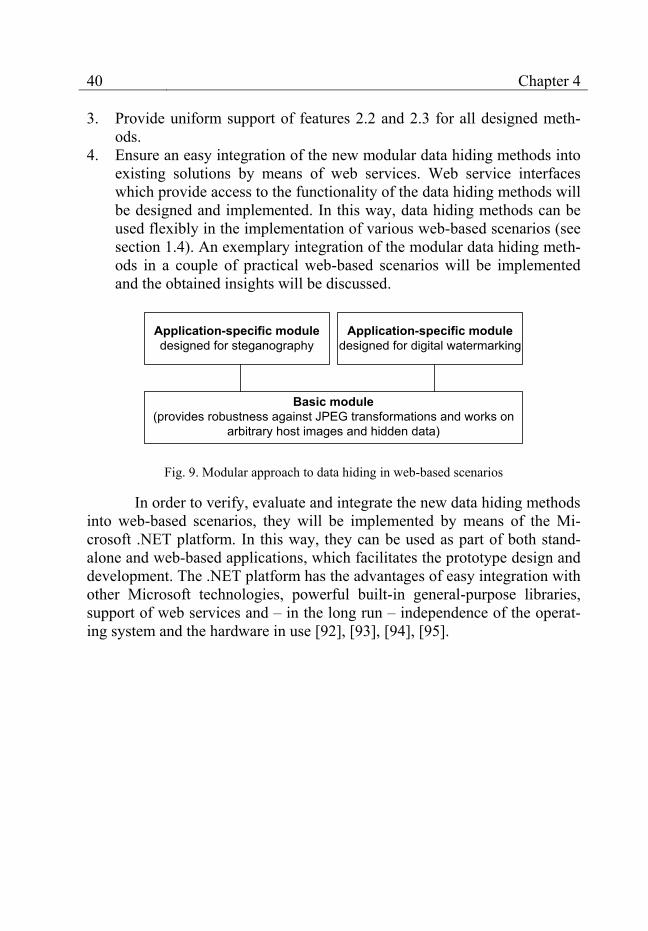
The decoding is started by calling the Decode method of the applica-tion-specific module and consists of only two stages in contrast to the encod-ing (fig. 13). First, the Decode method of the basic module is called to ex-tract the hidden bit values. Then, the application-specific module processes them and returns the result to the application.
Fig. 13. Data decoding – sequence diagram
As long as the basic and the application-specific modules implement their respective methods as described, they could contribute arbitrary fea-tures to the data hiding methods. For example, the DCTHiderEngine class provides robustness against JPEG transformations but cannot hide a lot of information. An LSBHiderEngine class, which encodes the bit values in the least significant bits of the RGB values of every image pixel, cannot survive JPEG compression but can hide much more information without impairing the image quality.
The basic modules can be used in conjunction with different applica-tion-specific modules such as the StegoHider or the WatermarkHider. The StegoHider class implements a steganographic application-specific module whose aim is to hide as much information as possible in the picture. The Wa-termarkHider class defines a watermarking method which is capable of de-tecting unauthorized image modifications. The method can also recover a
44 Chapter 5
hidden watermark after such modifications have been made but the maxi-mum length of the watermark is limited.
This modular architecture of data hiding methods enables the crea-tion and adaptation of application-specific modules according to different requirements under the preservation of all features provided by the basic module in use. Therefore, the basic module should provide the essential fea-tures, which are common for all data hiding methods and are unlikely to change. The application-specific module, on the other hand, should provide the more specialized and often more complex high-level features of the data hiding method. The overall method features are then a combination of the features provided by its basic module and its application-specific module. Moreover, methods using the same basic module are guaranteed to have a uniform implementation of the features provided by it, which improves qual-ity and facilitates their usage.
5.2 Basic module resistant to JPEG transformations
The basic module presented in this section is designed to enable the usage of data hiding methods on images that are compressed and saved in the JPEG image format. It can be incorporated into both steganographic and digital watermarking methods.
5.2.1 Major design goals
In accordance with the discussions in sections 2.2 and 2.3, the major goals of the basic module can be defined as follows: 1. Provide robustness against JPEG transformations: compression, decom-
pression and recompression. The processing of the JPEG format should be encapsulated in the basic module, so that any application-specific modules remain independent of the underlying web-relevant compres-sion format.
2. Enable the processing of arbitrary images and arbitrary secret infor-mation. For this purpose, the secret information should be treated as an arbitrary bit stream.
3. Allow the extraction of the hidden secret information from the host im-age without any knowledge about the image prior data hiding. Such a blind scheme gives the application-specific module a maximum degree of freedom with regard to the development of desired method features.
4. Allow an error-free extraction of the hidden secret information. In this way the application-specific module and any applications using the
Extendable data hiding methods 45
method can rely on the reliable storage of the information and do not need to implement their own error-correction schemes.
The simultaneous achievement of these four design goals is far from trivial. JPEG is inherently a lossy image format [41] and the achievement of an error-free recovery of the hidden information after JPEG transformations is not easy. Coupled with the usage of arbitrary secret information and blind information retrieval, it necessitates the intimate knowledge of the JPEG compression and decompression processes as defined by the JPEG standard [41] and the JPEG File Interchange Format (JFIF) [42]. Since the standard does not completely define the compression process, knowledge of the major JPEG implementations can be of advantage, too.
5.2.2 Overview of the JPEG Standard
In this section a short overview of the JPEG image standard is pre-sented in order to facilitate the presentation of the encoding and decoding methods created for the basic module.
The JPEG standard was created by the Joint Photographic Experts Group in 1992 [41], [96]. It involves mathematical transformations, a lossy compression step as well as several lossless compression stages based on predictive and Huffman or arithmetic coding and achieves typical compres-sion ratios of 10:1 and more.
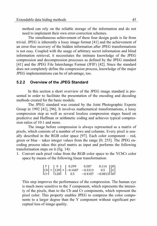
The image before compression is always represented as a matrix of pixels, which consists of a number of rows and columns. Every pixel is usu-ally described in the RGB color space [97]. Each color component – red, green or blue – takes integer values from the range [0; 255]. The JPEG en-coding process takes this pixel matrix as input and performs the following transformation steps on it (fig. 14): 1. Convert each pixel value from the RGB color space to the YCbCr color
space by means of the following linear transformation:
[
] [
] [
] [ ]
This step improves the performance of the compression. The human eye is much more sensitive to the Y component, which represents the intensi-ty of the pixels, than to the Cb and Cr components, which represent the pixel color. This property enables JPEG to compress the color compo-nents to a larger degree than the Y component without significant per-ceptual loss of image quality.

46 Chapter 5
RGB image YCbCr image
RGB → YCbCrconversion
Zero-centered component values
Subtract 128 from each pixel value
23 24 21 30 23 -29 -40 -28
14
18
10
34
79
-90
-80
16 18 32 -34 -30 -33 -32
15 20 20 -33 -36 -21 -23
12 0 -56 -43 -37 -39 -40
35 36 0 -45 -40 -44 -43
78 80 79 78 82 43 98
-98 23 45 -34 5 56 67
-56 8 -5 -87 23 34 20
8x8 image blocks
Divide each component into blocks
...
...Perform DCT on each block
DCT values
Step 1 Step 2
Step 3
Step 4
Quantize DCT values
Step 5
Quantized DCT values
Round quantized DCT valuesStep 6
23 24 21 30 23 -29 -40 -28
14
18
10
34
79
-90
-80
16 18 32 -34 -30 -33 -32
15 20 20 -33 -36 -21 -23
12 0 -56 -43 -37 -39 -40
35 36 0 -45 -40 -44 -43
78 80 79 78 82 43 98
-98 23 45 -34 5 56 67
-56 8 -5 -87 23 34 20
Rounded quantized DCT values
Lossless compression
Step 8
Binary JPEG file
Number DCT values in
zigzag order
Step 7
Ordered rounded quantized DCT values
23 24 21 30
-56
20
32
012
15
16
10
18
14
20
18
23 24 21 30
-56
20
32
012
15
16
10
18
14
20
18
Fig. 14. JPEG encoding overview
2. Subtract 128 from all pixel components in the YCbCr color space in or-der to center the value range on zero. This step improves the perfor-mance of the discrete cosine transform (DCT).
3. Divide each component of the image into blocks. If the image di-mensions are not divisible by 8, supply dummy rows or columns. The JPEG compression performs best if the adjacent pixels of the image block have similar values. Generally, most image blocks of size contain similar pixels and allow for better compression.
4. Perform a two dimensional DCT transformation on each individual block of every color component by means of the following mathematical for-mula:
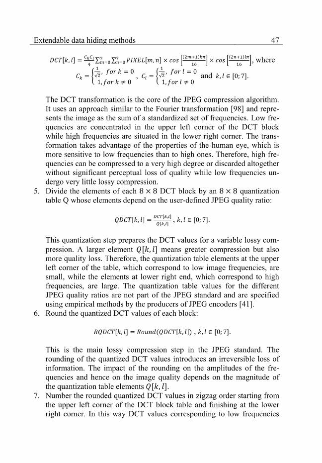
Extendable data hiding methods 47
[ ]
∑ ∑ [ ] [
( )
]
[
( )
], where
{
√
, {
√
and [ ].
The DCT transformation is the core of the JPEG compression algorithm. It uses an approach similar to the Fourier transformation [98] and repre-sents the image as the sum of a standardized set of frequencies. Low fre-quencies are concentrated in the upper left corner of the DCT block while high frequencies are situated in the lower right corner. The trans-formation takes advantage of the properties of the human eye, which is more sensitive to low frequencies than to high ones. Therefore, high fre-quencies can be compressed to a very high degree or discarded altogether without significant perceptual loss of quality while low frequencies un-dergo very little lossy compression.
5. Divide the elements of each DCT block by an quantization table Q whose elements depend on the user-defined JPEG quality ratio:
[ ] [ ]
[ ] , [ ].
This quantization step prepares the DCT values for a variable lossy com-pression. A larger element [ ] means greater compression but also more quality loss. Therefore, the quantization table elements at the upper left corner of the table, which correspond to low image frequencies, are small, while the elements at lower right end, which correspond to high frequencies, are large. The quantization table values for the different JPEG quality ratios are not part of the JPEG standard and are specified using empirical methods by the producers of JPEG encoders [41].
6. Round the quantized DCT values of each block:
[ ] ( [ ]) , [ ]. This is the main lossy compression step in the JPEG standard. The rounding of the quantized DCT values introduces an irreversible loss of information. The impact of the rounding on the amplitudes of the fre-quencies and hence on the image quality depends on the magnitude of the quantization table elements [ ].
7. Number the rounded quantized DCT values in zigzag order starting from the upper left corner of the DCT block table and finishing at the lower right corner. In this way DCT values corresponding to low frequencies

48 Chapter 5
obtain low indices while DCT values corresponding to high frequencies obtain high indices. This step is designed to improve the performance of the run-length lossless compression performed in the next step.
8. Perform lossless compression on the rounded quantized DCT values us-ing predictive and run-length coding.
RGB image
Create DCT block table
Step 1 Step 2
Step 4
Step 5Step 6
23 24 21 30 23 -29 -40 -28
14
18
10
34
79
-90
-80
16 18 32 -34 -30 -33 -32
15 20 20 -33 -36 -21 -23
12 0 -56 -43 -37 -39 -40
35 36 0 -45 -40 -44 -43
78 80 79 78 82 43 98
-98 23 45 -34 5 56 67
-56 8 -5 -87 23 34 20
Binary JPEG file
Step 7
Ordered quantized integer DCT values
Decode quantized integer DCT values
Quantized integer DCT values
Step 3
Multiply by quantization
table Q
DCT values of the 8x8 image blocks
Perform inverse DCT on each block
23 24 21 30 23 -29 -40 -28
14
18
10
34
79
-90
-80
16 18 32 -34 -30 -33 -32
15 20 20 -33 -36 -21 -23
12 0 -56 -43 -37 -39 -40
35 36 0 -45 -40 -44 -43
78 80 79 78 82 43 98
-98 23 45 -34 5 56 67
-56 8 -5 -87 23 34 20
Zero-centered component values
Assemble each image component
from its blocks
YCbCr image
Add 128 to each pixel value
YCbCr → RGB conversion
8x8 image blocks
...
...
23 24 21 30
-56
20
32
012
15
16
10
18
14
20
18
23 24 21 30
-56
20
32
012
15
16
10
18
14
20
18
Fig. 15. JPEG decoding overview
The JPEG decoding process reverses the aforementioned steps, be-ginning with the compressed JPEG binary file as an input (fig. 15): 1. Perform lossless decompression on the binary content of the JPEG file in
order to obtain the ordered quantized integer DCT values of each image block.
2. Create a DCT block table from the ordered quantized integer DCT val-ues.
3. Multiply the quantized DCT values of each image block by the corre-sponding elements of the quantization table Q, which was used during the encoding and saved in the JPEG file headers:
[ ] [ ] [ ], [ ].
4. Perform an inverse two-dimensional DCT transformation on the DCT values from the previous step in order to obtain the pixel values of each image block:
[ ] ∑ ∑
[ ] [
( )
]
[
( )
], where

Extendable data hiding methods 49
{
√
, {
√
and [ ].
5. Assemble the different image components by putting the corresponding
image blocks together. Discard any dummy lines that have been added by the JPEG encoding algorithm.
6. Add 128 to all image components to negate the centering on zero and obtain values in the range [0; 255].
7. Perform a conversion of all pixel values defined by the components of the YCbCr color space to the RGB color space as follows:
[ ] [
] [
].
The basic module of the discussed data hiding methods includes a
model of the JPEG standard up to the lossless compression step. The data hiding algorithm operates mainly on the quantized DCT values as explained in the next sections.
5.2.3 Basic module: encoding
The encoding of information in the basic module is divided into two stages: the PrepareToEncode stage and the FinishEncode stage (see section 5.1).
Image
Divide the image into 8x8 blocks
Step 1
Image comprised of 8x8 blocks
Determine the number of
embeddable bits in each block
Step 2
23 24 21 30 23 45 36 34
14
18
10
34
44
33
34
16 18 32 45 34 33 32
15 20 20 33 36 31 23
12 22 56 35 37 39 30
35 36 0 34 40 39 38
40 29 56 38 50 43 40
32 23 45 34 5 56 48
31 18 31 30 23 34 20
23 24 21 30 23 45 36 34
14
18
10
34
44
33
34
16 18 32 45 34 33 32
15 20 20 33 36 31 23
12 22 56 35 37 39 30
35 36 0 34 40 39 38
40 29 56 38 50 43 40
32 23 45 34 5 56 48
31 18 31 30 23 34 20
Communicate the results to the
application-specific module
Step 3
Number of embeddable bits per block
Information returned to the application-specific module
Fig. 16. Basic module – PrepareToEncode stage
The PrepareToEncode stage (fig. 16) consists of the following steps: 1. The image is divided into the same pixel blocks that are character-
istic for the JPEG standard. In addition, the number of pixel blocks in horizontal and in vertical direction is calculated:
;

50 Chapter 5
.
The for this basic module is always equal to 8 pixels.
2. The next task of the PrepareToEncode stage is to determine the maxi-mum amount of information that can be hidden in each pixel block. The information is embedded into the rounded quantized DCT values: [ ] (see the previous section). The embeddable amount can be made dependent on various features of the block and some blocks may be skipped altogether. As described, the JPEG standard discards high frequencies in the image and keeps low ones. This means that DCT values which have a high in-dex number after the zigzag ordering step (i.e. they correspond to high image frequencies) tend to be discarded while DCT values which have a low index number will be still present in the image after the JPEG com-pression. The algorithm chosen in this book uses this property and estab-lishes a boundary inside the sequence of 64 ordered DCT values of the block. This boundary divides the frequencies that are present in the im-age from those that are not (fig. 17). Information is hidden only in the DCT values with an index lower than or equal to the index at which the boundary has been placed.
DCT value0
DCT value63
Lower frequencies
Higher frequencies
Boundary dividing the frequencies present in the image block from the frequencies that are missing
Hide information in these DCT values Skip these DCT values
Fig. 17. DCT values – selection
The boundary is placed dynamically depending on the properties of the image block – typically between indices 30 and 45. If one bit per DCT value is hidden, then there are between 30 and 45 bits embeddable per image block. This maximum amount is calculated for each image block
3. The number of pixel blocks in each direction calculated in step 1 and the maximum amounts of embeddable information for each pixel block de-termined in step 2 are communicated to the application-specific module.
The FinishEncode stage (fig. 18) takes the actual bits which have to be hidden in each image block as an input from the application-specific module. The bit values can form arbitrary binary sequences. The only re-

Extendable data hiding methods 51
striction is that the number of bits per block has to be less than the maximum amount of bits embeddable in that same block, which has been determined in the PrepareToEncode stage. If the restriction is satisfied (i.e. the information to embed is not too large for the image), the algorithm proceeds as follows:
Binary information to hide in each 8x8 block
Image comprised of 8x8 blocks
23 24 21 30 23 45 36 34
14
18
10
34
44
33
34
16 18 32 45 34 33 32
15 20 20 33 36 31 23
12 22 56 35 37 39 30
35 36 0 34 40 39 38
40 29 56 38 50 43 40
32 23 45 34 5 56 48
31 18 31 30 23 34 20
Encode the information
into each block
Step 1
Guarantee JPEG decompression
Step 2
23 24 21 30 23 45 36 34
14
18
10
34
44
33
34
16 18 32 45 34 33 32
15 20 20 33 36 31 23
12 22 56 35 37 39 30
35 36 0 34 40 39 38
40 29 56 38 50 43 40
32 23 45 34 5 56 48
31 18 31 30 23 34 20
DImage with encoded
informationRobustness against JPEG
decompression (D)
Guarantee JPEG compression and
recompression
Step 3
23 24 21 30 23 45 36 34
14
18
10
34
44
33
34
16 18 32 45 34 33 32
15 20 20 33 36 31 23
12 22 56 35 37 39 30
35 36 0 34 40 39 38
40 29 56 38 50 43 40
32 23 45 34 5 56 48
31 18 31 30 23 34 20
D C RRobustness against
JPEG compression (C) and recompression (R)
Step 4Reduce the difference from the original image
Resulting image of improved quality
Fig. 18. Basic module – FinishEncode stage
1. The bit values are encoded in the least-significant bits of the quantized DCT values of the image block starting at the DCT value with index one. During the encoding process care is taken to minimize the impact of the modifications on the quantized DCT values and to improve the overall image quality – i.e. to minimize the difference between the original im-age and the image containing the embedded information.
2. Guarantee that the embedded information remains intact after JPEG de-compression. The decompression of an image from JPEG back to a ma-trix of RGB pixels always involves some errors due to rounding and the conversion between image spaces. The method performs an internal JPEG decompression check for such errors. If errors are detected, a small correction to the DCT values is made to negate them.
3. Guarantee that the hidden information survives JPEG compression and recompression by arbitrary programs. As the JPEG standard does not de-fine the values of the elements of the quantization tables responsible for the lossy compression, the method has to ensure information survival under the usage of arbitrary quantization tables. This is achieved by guaranteeing that the hidden information stays intact after quantization with any quantization table having elements
. The quanti-zation table represents a threshold defining the maximum tolerable

52 Chapter 5
JPEG compression ratio. It can be meaningfully set after performing a short research of the quantization tables used by various popular image processing software vendors such as Adobe, Microsoft, Corel, etc.
4. Reduce the difference between the original image and the image after data hiding. The previous steps are designed to keep image distortions low but they introduce some unavoidable differences between the pixel values before and after data hiding. These differences can be further min-imized by tweaking or adding suitable DCT values to the image block. In this way the overall image quality will be improved.
The data hiding steps described above are repeated for each image block. After the algorithm has finished, the resulting image containing the hidden information is passed back to the application-specific module.
9 24 21 16
14
18
10
8 12 7
4 20 3
12 22 10
9 24 21 16 18 8 6 15
14
18
10
11
24
18
11
8 12 7 15 8 10 12
4 20 3 10 4 9 23
12 22 10 14 22 19 16
18 15 0 22 5 16 6
14 12 11 23 14 12 18
9 23 21 10 5 14 22
14 18 15 0 21 8 12
Image
Divide the image into 8x8 blocks
Step 1
Image comprised of 8x8 blocks
Determine the number of bits
embeddable into each block
Step 2
Communicate the results to the
application-specific module
Step 4
Maximum number of embeddable bits per block
Information passed to the application-specific module
Binary information from each 8x8 block
Step 3Decode the corresponding number of bit values from each DCT block
...
...
Fig. 19. Basic module – decoding
5.2.4 Basic module: decoding
In contrast to the encoding, the decoding process consists of only one stage (fig. 19), which is similar to the PrepareToEncode encoding stage: 1. The input image is divided into pixel blocks and the information
about the number of blocks in horizontal and vertical direction and the block size (always equal to 8 pixels for this basic module) is passed to the application-specific module.
2. The maximum amount of embeddable data for each pixel block is deter-mined using the same boundary algorithm which was described in the previous section (fig. 17).
Extendable data hiding methods 53
3. For each block, the corresponding number of bit values is read from the least-significant bits of the quantized DCT values [ ] (see sec-tion 5.2.2) starting at the DCT value with index one.
4. After the processing of all image blocks, the obtained bit values are passed to the application-specific module.
5.2.5 Achieving robustness against JPEG transformations
Achieving accurate data embedding in the case of JPEG is not a trivi-al task due to the room for discretion provided in the JPEG specification and the integer implementations of color spaces and transformations. Thus, the JPEG standard alone is not sufficient. An intimate knowledge of the most popular variations of the standard [6] is required as one cannot know in ad-vance what image processing libraries will be used to edit the image after the signature embedding.
The method considers sequentially the compression, decompression and recompression of JPEG images. As we use an embedding into the least significant bits of the DCT coefficients, the robustness against compression is implicitly guaranteed as well as a good image quality for a large size of the embedded data [3]. This kind of embedding is sufficient for a probabilis-tic conclusion about the presence of a pre-specified signature in the image but it poses problems if unknown signatures have to be extracted accurately from the image. The problem can be alleviated by the use of error-correcting codes but they still cannot guarantee a reliable signature extraction. There are two causes for the loss of accuracy during decompression: 1. The first cause is related to the integer implementations of the transfor-
mations (steps 1 and 3 of the JPEG standard). 2. The second cause is related to the limited integer representation of the
color spaces – often using subsets of the set of natural numbers .
The integer implementation of the transformations (finite accuracy of all variables) causes small rounding errors, which, in some rare cases, pose the danger of flipping one of the embedded data bits. This situation can be resolved relatively easy by calculating a chain of forward and inverse image transformations (stages 1 to 3 of the algorithmic description below). The co-efficients Ck,l reaching stage 4 do not exhibit any rounding error problems.
The limited integer representation of the color spaces causes a more serious problem related to the lossy compression, which achieves infor-mation reduction by mapping multiple similar variations of a pixel block on-to the same DCT block. The reverse mapping is unique. If some of the origi-

54 Chapter 5
nal pixel values before the compression have values close to the boundaries of the set S, some pixel values obtained after the decompression could drop out. Most image processing programs change such values to either 0 or 255. As a result, the changed pixel block may now map onto a different DCT block leading to the loss of the embedded data. Our solution is to pre-scale the pixel values so that the reverse mapping always yields valid values (stag-es 4 and 5 of the algorithmic description below).
The adjustment coefficient α is set empirically at stage 0. If no changes in the reconstructed pixel values have been observed at stage 5, it may be increased dynamically by small amounts, which was not necessary so far for our tests. Each color channel is processed separately. By making multiple iterations we achieve fine control over the image quality and modi-fy the pixel values only to the extent necessary to ensure robustness against JPEG decompression.
Let us now consider the robustness of the embedded data against JPEG recompression. We want to make the data robust against recompres-sion with }7,...,2,1,0{,| ,
)(,
)( lkforQQQ lkjlk
j , where j is an iteration
index and Q is the quantization table corresponding to the user-specified JPEG quality ratio.
The initial tests indicate that the embedded data is in itself fairly ro-bust against JPEG recompression with smaller quantization coefficients but this varies depending on Q, the amount of the data and the image textures. If no additional care is taken, the embedded data cannot be extracted reliably after recompression. In order to ensure the reliability of the extraction, we employ a modified Quantization Index Modulation technique [12]. By means of the quantization step qk,l, we can choose multiple new values )(
,ilkC of the
same coefficient lkC , , which represent the same embedded data (stages 7 and 8 of the algorithmic description below). The coefficient β is initialized to 1. If for a given Q(j) and dataZlk ),( , ),(
,)(
,ji
lkilk EC then the whole JPEG block
is considered robust against recompression with Q(j). The choice and the number of the quantization tables Q(j) depends on the implementations of the JPEG format such as the open-source IJG library, Adobe Photoshop, Paint Shop Pro and others. At this prototype stage, we test all possible Q(j) for bet-ter evaluation of the proposed method.
For optimization purposes and better image quality (minimum mean squared error between the original image and the image after the embed-ding), we may unite the separate iteration cycles (stages 1 to 5 and stages 6 to 9) into a single iteration cycle. A final quality improvement may also be

Extendable data hiding methods 55
achieved by a further stepwise replacement of some of the DCT values with their non-integer counterparts Bk,l. Then, the image is reconstructed and pre-sented to the user.
Algorithmic description of the proposed method: Let us assume that the coefficients lkC , have already been calculated
and data has been embedded into some of them. Let us also define the set }|),{( , dataembeddedcontainsClkZ lkdata , 7,...,2,1,0, lk . Then, the
algorithmic description of the proposed method can be summarized as fol-lows: Stage 0. Perform initialization: 1i , 0)0( u , 255)0( v , 1 . Stage 1. Calculate )1(
,nmP from lkC , by performing the inverse steps of JPEG [5, 6].
Stage 2. Calculate )1(,lkC from )1(
,nmP following steps 1 to 3 of the JPEG stand-ard
Stage 3. If )1(,,|),( lklkdata CCZlk , then for dataZlk ),( , set )1(
,, lklk CC and go back to stage 1.
Stage 4. Calculate )2(,nmP from lkC , by performing the inverse steps of JPEG
[5, 6]. Stage 5. If },...,1,{|),( )0()0()0()2(
, vuuPnm nm , then for )0()2(,|),( uPnm nm
calculate )0()2(,
|),(
)()0()2(
,
max uPs nmuPnm
i
nm
and for
)0()2(,|),( vPnm nm calculate )0()2(
,|),(
)()0()2(
,
max vPt nmvPnm
i
nm
. Set
)()1()( iii suu , )()1()( iii tvv . For )(,|),( inm uPnm , set
)(,
inm uP and for )(
,|),( inm vPnm , set )(
,i
nm vP . Increase i by 1 and go back to stage 1.
Stage 6. Set 0i , 1 , choose a valid )(| jQj and for ),( lk , set
lklk CC ,)0(
, .
Stage 7. Calculate )(,,
)(,
),(, / j
lklkilk
jilk QQCD and lk
jlk
ilk
jilk QQDE ,
)(,
)(,
),(, / .
Stage 8. If ),(,
)(,|),( ji
lkilkdata ECZlk , then set
])1[()1( ,)(
,)1(
, lkii
lkilk qiCC , where lkN
lkq ,2, and lkN , is the number of data bits in lkC , . Increase i by 1 and go back to stage 7.
56 Chapter 5
Stage 9. Repeat stages 6 to 8 for dataZlk ),( and )(| jQj .
5.2.6 Conclusion
The basic module developed in this book encapsulates all JPEG-related properties and allows the application-specific modules to concentrate on the provision of other important method features.
As it can be seen from the previous two sections, the encoding and the decoding involve different number of steps and require different amount of time. The most time-consuming encoding steps are part of the FinishEn-code stage and have no equivalent in the decoding process. Consequently, the decoding takes less time to complete than the full encoding process.
5.3 A modular steganographic method
The presented steganographic method uses the basic module de-scribed in section 5.2 to hide as much information as possible into a JPEG file. In addition, the method aims at minimizing the image distortions caused by the data hiding process. In this way, sensitive information can be easily transmitted over the Internet and processed by web-based tools.
The method takes an arbitrary binary file as an input. Then, its appli-cation-specific module appends some specialized headers containing infor-mation about the file length and the file name as well as the use of error-correcting codes. The resulting binary information is then subjected to op-tional error-correction and randomization procedures. Finally, it is passed to the basic module for encoding into the JPEG image.
5.3.1 File Headers
The file headers contain information about the processed file and some important data hiding parameters. The headers are divided into several distinct sections (fig. 20). The first one is a general section containing infor-mation about the use of error-correcting codes and the lengths or the pres-ence of the other header sections. The second section contains information about the file length and the third section contains the file name.
The length of the different header sections (and hence the overall header length) is variable and depends on the individual file properties (length and name). The application (or its human user) has some degree of control over the file headers, as well. It can choose whether or not error-

Extendable data hiding methods 57
correcting codes are enabled and it can omit the saving of the file name if it is not necessary.
General section
Use of ECC, length of the file length section, storage of the file name
File length section
Contains the file length
File name section
Contains the file name ...
File content
Fig. 20. Steganographic method – file headers
The optional use of error-correcting codes raises the robustness of the saved information against unforeseen image modifications. The trade-off is that more information needs to be embedded into the image, which increases slightly the amount of image distortions.
5.3.2 Error-correcting codes
Error-correcting codes increase the tolerance of the hidden infor-mation to minor image modifications. There are different variants of such codes: Hamming codes, Reed-Solomon codes, turbo codes, etc. Each one of them has different properties and can detect and recover different amounts of bit errors [99], [100].
The error-correcting codes used in this data hiding method are based on the Hamming algorithm and allow the reliable detection and recovery of single-bit errors. Their use is optional and depends on the preferences of the calling application.
The Hamming algorithm works on a stream of indexed bits. It adds new error-correcting bits at all positions with indices equal to [ ). During this addition, existing bit values are shifted to the right to make place for the error-correcting bits. Their indices are increased and, hence, the over-all bit-stream length is increased, too (fig. 21).
The value of each error-correcting bit is determined by a parity func-tion whose arguments consist of bit values at strictly specified positions in the bit-stream. The clever selection of these positions allows the detection of the exact location of an arbitrary single-bit error.
To detect an error, all error-correcting bits are taken out of the bit-stream and placed next to each other in the order of their appearance. To-gether, they form an error-correcting value, which is equal to zero if no er-rors are present and if even parity is used. If the value is greater than zero, it indicates the position of the single-bit error in the bit-stream. In order to fix the error, the bit value at that position has to be flipped.
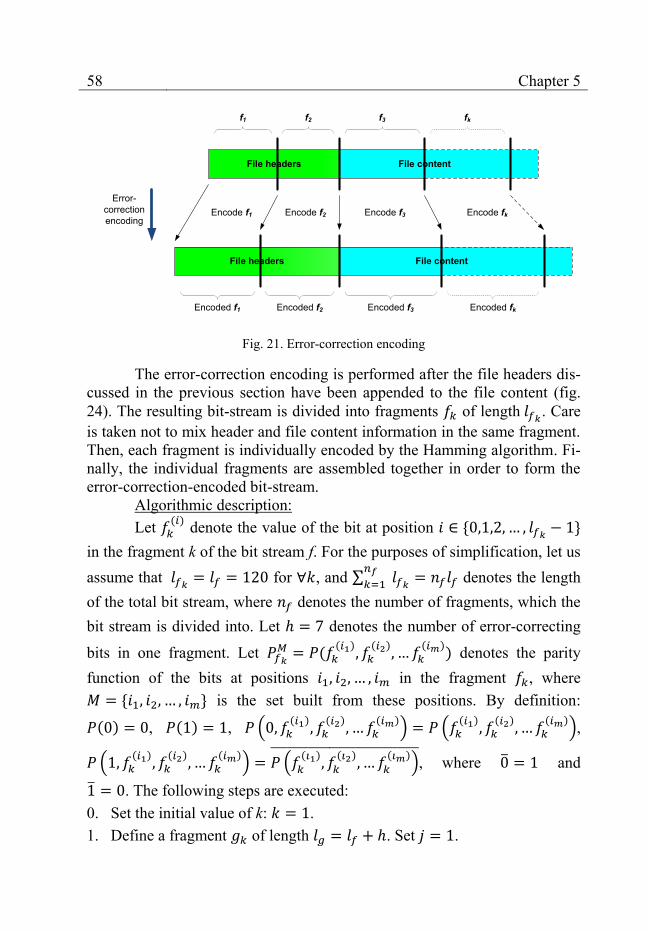
58 Chapter 5
File headers File content
File headers File content
Error-correction encoding
Encode f1 Encode f2 Encode f3 Encode fk
f1 f2 f3 fk
Encoded f1 Encoded fkEncoded f3Encoded f2
Fig. 21. Error-correction encoding
The error-correction encoding is performed after the file headers dis-cussed in the previous section have been appended to the file content (fig. 24). The resulting bit-stream is divided into fragments of length
. Care is taken not to mix header and file content information in the same fragment. Then, each fragment is individually encoded by the Hamming algorithm. Fi-nally, the individual fragments are assembled together in order to form the error-correction-encoded bit-stream.
Algorithmic description: Let
( ) denote the value of the bit at position
in the fragment k of the bit stream f. For the purposes of simplification, let us assume that
for , and ∑
denotes the length of the total bit stream, where denotes the number of fragments, which the bit stream is divided into. Let denotes the number of error-correcting
bits in one fragment. Let
( ( )
( ) ( )
) denotes the parity function of the bits at positions in the fragment , where is the set built from these positions. By definition:
( ) , ( ) , ( ( )
( ) ( )
) ( ( )
( ) ( )
),
( ( )
( ) ( )
) ( ( )
( ) ( )
) , where and
. The following steps are executed: 0. Set the initial value of k: . 1. Define a fragment of length . Set .

Extendable data hiding methods 59
2. For , set ( )
( ). If
then j is increased by 1 and the execution goes back to step 1. Otherwise, proceed to step 3.
3. Set . 4. Define . Set
( ) . Define the set
which contains as elements the following bit positions in : ( )
( ) ( ) , where .
5. Set ( )
. If then b is increased by 1 and the execu-
tion goes back to step 4. Otherwise, proceed to step 6. 6. If then k is increased by 1 and the execution goes back to step 1.
Dividing the bit-stream into fragments, results in greater flexibility with regard to error-correction. In the variant presented above, one single-bit error per bit-stream fragment can be successfully recovered. An increase in the number of fragments, leads to improved error-correcting capabilities. In addition, the algorithm for error-correction can be different for the different bit-stream fragments. Its choice may be motivated by the relative importance of each fragment, by the statistical properties of the bit-stream or the JPEG host image or by other user-defined criteria.
5.3.3 Randomization
Another optional step taking place after the error-correction and be-fore the actual encoding of the binary data into the JPEG image (the Fin-ishEncode stage of the basic module) is the randomization step.
The randomization utilizes a pseudo-random generator [101] to cre-ate pseudo-random permutations. These permutations are used to select the image block into which each subsequent bit of the bit-stream is embedded. The result is a pseudo-random distribution of the embedded bit-values across the image.
The exact type of the pseudo-random generator is of little signifi-cance as long as its seed uniquely determines the generated pseudo-random number sequence. One sample complimentary-multiply-with-carry (CMWC) pseudo-random generator proposed by Marsaglia [102] is presented as a C code in fig. 22. The initial values of the vector Q represent the generator seed.

60 Chapter 5
static unsigned long Q[4096], c=123;
unsigned long CMWC_4096(void){
unsigned long long t, a = 18782LL;
static unsigned long I = 4095;
unsigned long x, m = 0xFFFFFFFE;
i = (i + 1) & 4095;
t = a * Q[i] + c;
c = (t >> 32);
x = t + c;
if(x < c){ x++; c++; }
return (Q[i] = m - x);
}
Fig. 22. Marsaglia’s CMWC_4096 pseudo-random generator
Normal sequential block order
Unmodified blocks
Blocks containing embedded information
8 4 14 6
2
12
16
157
1
13
10
5
11
9
3
1 2 3 4
16
12
8
1514
10
6
13
9
5
11
7
Pseudo-random block order
Fig. 23. Pseudo-random image block order
The most important implication of the randomization step concerns security. The seed of the pseudo-random generator can be made dependent on a user-specified password thus raising the level of security of the pro-posed steganographic method.
Another important implication is the improvement of the overall per-ceived image quality. If the image blocks, into which information is embed-ded, are scattered across the image, there is no large image area, where the image quality has deteriorated significantly (fig. 23). Otherwise, if no ran-domization was applied, the blocks containing embedded information would be chosen in a sequential order beginning from top to bottom and from left to right. This would lead to a worse perceived image quality in the top left im-age area where the information is hidden and a better quality near the bottom right image corner where the image blocks are intact.

Extendable data hiding methods 61
5.3.4 Encoding
The encoding process incorporates the header creating, the error-correcting and the block randomizing procedures described in the previous sections. It aims at achieving robust and visually imperceptible data hiding and consists of the following steps (fig. 24):
Binary file
Step 2
23 24 21 30 23 45 36 34
14
18
10
34
44
33
34
16 18 32 45 34 33 32
15 20 20 33 36 31 23
12 22 56 35 37 39 30
35 36 0 34 40 39 38
40 29 56 38 50 43 40
32 23 45 34 5 56 48
31 18 31 30 23 34 20
Invoke PrepareToEncode
Number of embeddable bits per image block
Distribute the binary information uniformly
across the blocks
Binary information distributed uniformly across the blocks
Randomize the block hiding order
Image containing embedded information
Header sectionsCreate and append the file headers
Step 1
File + file headers
Header sections
E C CApply error-
correcting codes
Step 3
Pseudo-random block order
8 4 14 6
2
12
16
157
1
13
10
5
11
9
3
Step 4
Step 5
Invoke FinishEncode
Binary information with error-correcting codes (ECC)
Pass the image to the application
Step 6Step 7 23 24 21 30
-56
20
32
012
15
16
10
18
14
20
18
23 24 21 30
-56
20
32
012
15
16
10
18
14
20
18
Web-based application
Fig. 24. Steganographic method – encoding
1. The file headers are created and appended to the file content. 2. The file content is encoded by means of the error-correcting codes
(Hamming algorithm) described in section 5.3.2. 3. The application-specific module calls the PrepareToEncode stage of the
basic module to get the overall number of image blocks and the maxi-mum amount of embeddable information for each block.
4. Randomization is applied to determine the order of the image blocks into which the bit values are embedded.
5. The binary information is distributed uniformly across the image blocks following the randomization order of the previous step.
6. The distributed binary information is passed to the FinishEncode stage of the basic module to be encoded into the JPEG image.
7. The image returned by FinishEncode, which contains the embedded in-formation, is passed to the calling application for saving or transmission over the Internet.
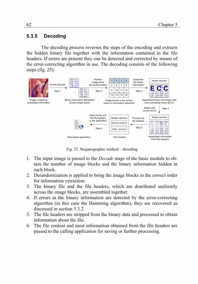
62 Chapter 5
5.3.5 Decoding
The decoding process reverses the steps of the encoding and extracts the hidden binary file together with the information contained in the file headers. If errors are present they can be detected and corrected by means of the error-correcting algorithm in use. The decoding consists of the following steps (fig. 25):
Image containing embedded information
Invoke Decode
Step 1 ...
...
Binary information distributed across image blocks
Step 4
Header sections
General section
Other sections
File headers Assembled information File+File headers
Header sectionsProcess the file headers
Step 5
Pass the file and the file headers
to the application
Step 6
Image blocks in the correct order for information extraction
1 2 3 4
16
12
8
1514
10
6
13
9
5
11
7
Performimage block
de-randomization
Step 2
Header sections
E C CAssembled binary information with
error-correcting codes (ECC)
Step 3
Assemble the binary information
Detect and correct errors
Web-based application
Fig. 25. Steganographic method – decoding
1. The input image is passed to the Decode stage of the basic module to ob-tain the number of image blocks and the binary information hidden in each block.
2. Derandomization is applied to bring the image blocks in the correct order for information extraction.
3. The binary file and the file headers, which are distributed uniformly across the image blocks, are assembled together.
4. If errors in the binary information are detected by the error-correcting algorithm (in this case the Hamming algorithm), they are recovered as discussed in section 5.3.2.
5. The file headers are stripped from the binary data and processed to obtain information about the file.
6. The file content and most information obtained from the file headers are passed to the calling application for saving or further processing.
Extendable data hiding methods 63
5.3.6 Conclusion
The steganographic method combines a simple application-specific module with the basic module presented in section 5.2. The application-specific module handles the file headers, the error-correction and the pseudo-random uniform distribution of the binary information across the image blocks. The amount of embeddable information is maximized and two new data hiding features are provided in addition to the robustness against JPEG transformations provided by the basic module.
The first feature is the ability to correct small errors in the hidden in-formation via the use of error-correcting codes. This is helpful if unexpected image modifications occur or if the JPEG file is otherwise damaged. The se-cond feature is the improved security via the usage of pseudo-random num-ber generators. The seeds of the generators are essential for the decoding of the embedded information and they can be made dependent on user-defined passwords.
In addition, the resulting steganographic method is blind – it does not need any kind of additional information to extract the binary data embedded in an image, which makes the method usable in various web-based scenarios. Finally, the method has a modular architecture and each one of the different features that it provides is encapsulated in either the basic or the application-specific module. This facilitates the support of the method and makes its en-hancement by the addition of new features easier.
5.4 A modular digital watermarking method
The modular digital watermarking method uses the basic module of section 5.2 to achieve robustness against JPEG transformation in close simi-larity to the steganographic method presented above.
The difference consists in the goals of the two methods. In contrast to the steganographic method, the digital watermarking method aims at hiding only a small amount of information called a watermark, which identifies the author, the end customer or the image itself (see also section 1.4). In addi-tion, the watermark has to be hidden in a robust way so that it survives image transformations.
The digital watermarking method developed in this book fulfills the new goals by introducing the following new features implemented in its ap-plication-specific module (fig. 26): 1. Detection of any image areas that have been modified after the embed-
ding of the watermark into the image.
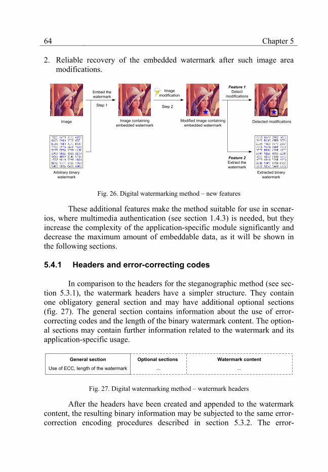
64 Chapter 5
2. Reliable recovery of the embedded watermark after such image area modifications.
Embed the watermark
Step 1
Image Image containing embedded watermark
Arbitrary binary watermark
Image modification
Step 2
Modified image containing embedded watermark
Feature 1Detect
modifications
Detected modifications
Feature 2Extract the watermark
Extracted binary watermark
Fig. 26. Digital watermarking method – new features
These additional features make the method suitable for use in scenar-ios, where multimedia authentication (see section 1.4.3) is needed, but they increase the complexity of the application-specific module significantly and decrease the maximum amount of embeddable data, as it will be shown in the following sections.
5.4.1 Headers and error-correcting codes
In comparison to the headers for the steganographic method (see sec-tion 5.3.1), the watermark headers have a simpler structure. They contain one obligatory general section and may have additional optional sections (fig. 27). The general section contains information about the use of error-correcting codes and the length of the binary watermark content. The option-al sections may contain further information related to the watermark and its application-specific usage.
General section
Use of ECC, length of the watermark ...
Watermark contentOptional sections
...
Fig. 27. Digital watermarking method – watermark headers
After the headers have been created and appended to the watermark content, the resulting binary information may be subjected to the same error-correction encoding procedures described in section 5.3.2. The error-
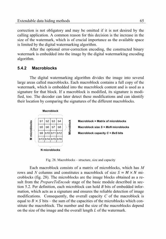
Extendable data hiding methods 65
correction is not obligatory and may be omitted if it is not desired by the calling application. A common reason for this decision is the increase in the size of the watermark, which is of crucial importance as the available space is limited by the digital watermarking algorithm.
After the optional error-correction encoding, the constructed binary watermark is embedded into the image by the digital watermarking encoding algorithm.
5.4.2 Macroblocks
The digital watermarking algorithm divides the image into several large areas called macroblocks. Each macroblock contains a full copy of the watermark, which is embedded into the macroblock content and is used as a signature for that block. If a macroblock is modified, its signature is modi-fied, too. The decoder can later detect these modifications and can identify their location by comparing the signatures of the different macroblocks.
b1 b2 b3 b4
b16
b12
b8
b15b14
b10
b6
b13
b9
b5
b11
b7
Macroblock
Mic
robl
ock Macroblock = Matrix of microblocks
Macroblock size S = MxN microblocks
Macroblock capacity C = BxS bits
N microblocks
M m
icro
bloc
ks
Fig. 28. Macroblocks – structure, size and capacity
Each macroblock consists of a matrix of microblocks, which has M rows and N columns and constitutes a macroblock of size mi-croblocks (fig. 28). The microblocks are the image blocks obtained as a re-sult from the PrepareToEncode stage of the basic module described in sec-tion 5.2. Per definition, each microblock can hold B bits of embedded infor-mation, which acts as a signature and ensures the reliable detection of image modifications. Consequently, the overall capacity C of the macroblock is equal to bits – the sum of the capacities of the microblocks which con-stitute the macroblock. The number and the size of the macroblocks depend on the size of the image and the overall length L of the watermark.
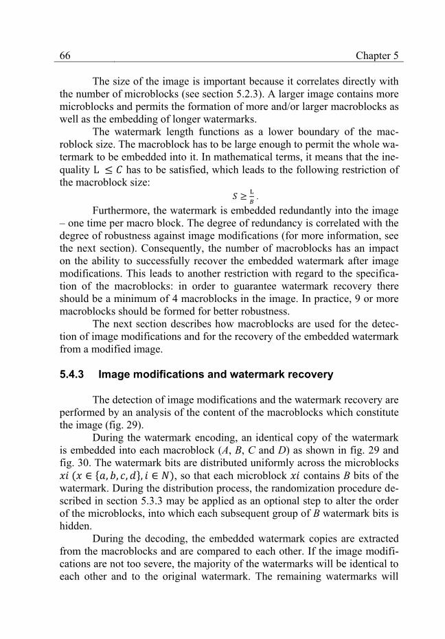
66 Chapter 5
The size of the image is important because it correlates directly with the number of microblocks (see section 5.2.3). A larger image contains more microblocks and permits the formation of more and/or larger macroblocks as well as the embedding of longer watermarks.
The watermark length functions as a lower boundary of the mac-roblock size. The macroblock has to be large enough to permit the whole wa-termark to be embedded into it. In mathematical terms, it means that the ine-quality has to be satisfied, which leads to the following restriction of the macroblock size:
.
Furthermore, the watermark is embedded redundantly into the image – one time per macro block. The degree of redundancy is correlated with the degree of robustness against image modifications (for more information, see the next section). Consequently, the number of macroblocks has an impact on the ability to successfully recover the embedded watermark after image modifications. This leads to another restriction with regard to the specifica-tion of the macroblocks: in order to guarantee watermark recovery there should be a minimum of 4 macroblocks in the image. In practice, 9 or more macroblocks should be formed for better robustness.
The next section describes how macroblocks are used for the detec-tion of image modifications and for the recovery of the embedded watermark from a modified image.
5.4.3 Image modifications and watermark recovery
The detection of image modifications and the watermark recovery are performed by an analysis of the content of the macroblocks which constitute the image (fig. 29).
During the watermark encoding, an identical copy of the watermark is embedded into each macroblock (A, B, C and D) as shown in fig. 29 and fig. 30. The watermark bits are distributed uniformly across the microblocks ( ), so that each microblock contains B bits of the watermark. During the distribution process, the randomization procedure de-scribed in section 5.3.3 may be applied as an optional step to alter the order of the microblocks, into which each subsequent group of B watermark bits is hidden.
During the decoding, the embedded watermark copies are extracted from the macroblocks and are compared to each other. If the image modifi-cations are not too severe, the majority of the watermarks will be identical to each other and to the original watermark. The remaining watermarks will
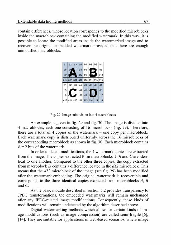
Extendable data hiding methods 67
contain differences, whose location corresponds to the modified microblocks inside the macroblock containing the modified watermark. In this way, it is possible to locate the modified areas inside the watermarked image and to recover the original embedded watermark provided that there are enough unmodified macroblocks.
a1 a2 a3 a4
a16
a12
a8
a15a14
a10
a6
a13
a9
a5
a11
a7
b1 b2 b3 b4
b16
b12
b8
b15b14
b10
b6
b13
b9
b5
b11
b7
d1 d2 d3 d4
d16
d12
d8
d15d14
d10
d6
d13
d9
d5
d11
d7
c1 c2 c3 c4
c16
c12
c8
c15c14
c10
c6
c13
c9
c5
c11
c7
A BDC
Fig. 29. Image subdivision into 4 macroblocks
An example is given in fig. 29 and fig. 30. The image is divided into 4 macroblocks, each one consisting of 16 microblocks (fig. 29). Therefore, there are a total of 4 copies of the watermark – one copy per macroblock. Each watermark copy is distributed uniformly across the 16 microblocks of the corresponding macroblock as shown in fig. 30. Each microblock contains B = 2 bits of the watermark.
In order to detect modifications, the 4 watermark copies are extracted from the image. The copies extracted form macroblocks A, B and C are iden-tical to one another. Compared to the other three copies, the copy extracted from macroblock D contains a difference located in the d12 microblock. This means that the d12 microblock of the image (see fig. 29) has been modified after the watermark embedding. The original watermark is recoverable and corresponds to the three identical copies extracted from macroblocks A, B and C.
As the basic module described in section 5.2 provides transparency to JPEG transformations, the embedded watermarks will remain unchanged after any JPEG-related image modifications. Consequently, these kinds of modifications will remain undetected by the algorithm described above.
Digital watermarking methods which allow for certain kinds of im-age modifications (such as image compression) are called semi-fragile [6], [14]. They are suitable for applications in web-based scenarios, where image
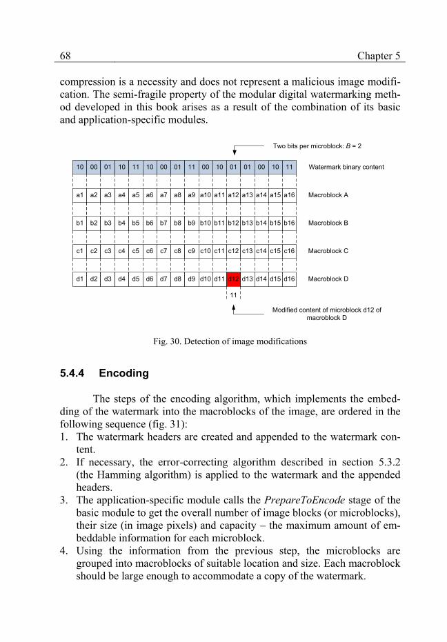
68 Chapter 5
compression is a necessity and does not represent a malicious image modifi-cation. The semi-fragile property of the modular digital watermarking meth-od developed in this book arises as a result of the combination of its basic and application-specific modules.
11
a1 a2 a3 a4 a5 a6 a7 a8 a9 a10 a11 a12 a13 a14 a15 a16
b1 b2 b3 b4 b5 b6 b7 b8 b9 b10 b11 b12 b13 b14 b15 b16
d1 d2 d3 d4 d5 d6 d7 d8 d9 d10 d11 d12 d13 d14 d15 d16
c1 c2 c3 c4 c5 c6 c7 c8 c9 c10 c11 c12 c13 c14 c15 c16
10 00 01 10 11 10 00 01 11 00 10 01 01 00 10 11 Watermark binary content
Macroblock A
Macroblock C
Macroblock B
Macroblock D
Modified content of microblock d12 of macroblock D
Two bits per microblock: B = 2
Fig. 30. Detection of image modifications
5.4.4 Encoding
The steps of the encoding algorithm, which implements the embed-ding of the watermark into the macroblocks of the image, are ordered in the following sequence (fig. 31): 1. The watermark headers are created and appended to the watermark con-
tent. 2. If necessary, the error-correcting algorithm described in section 5.3.2
(the Hamming algorithm) is applied to the watermark and the appended headers.
3. The application-specific module calls the PrepareToEncode stage of the basic module to get the overall number of image blocks (or microblocks), their size (in image pixels) and capacity – the maximum amount of em-beddable information for each microblock.
4. Using the information from the previous step, the microblocks are grouped into macroblocks of suitable location and size. Each macroblock should be large enough to accommodate a copy of the watermark.
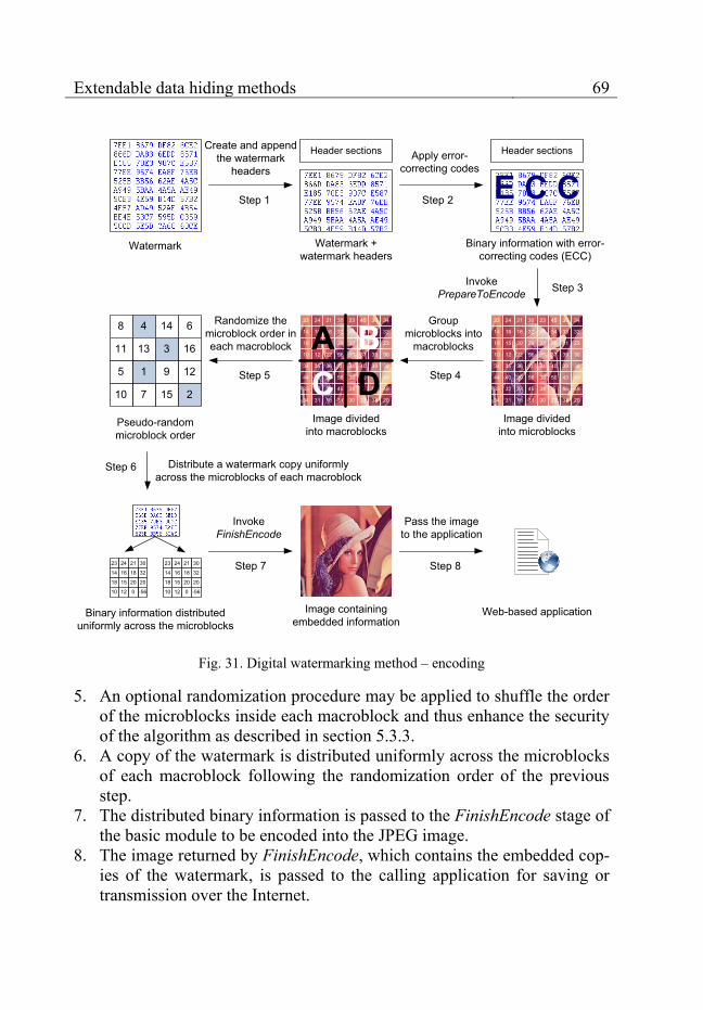
Extendable data hiding methods 69
Watermark
Step 2
23 24 21 30 23 45 36 34
14
18
10
34
44
33
34
16 18 32 45 34 33 32
15 20 20 33 36 31 23
12 22 56 35 37 39 30
35 36 0 34 40 39 38
40 29 56 38 50 43 40
32 23 45 34 5 56 48
31 18 31 30 23 34 20
Invoke PrepareToEncode
Image divided into microblocks
Distribute a watermark copy uniformly across the microblocks of each macroblock
Randomize the microblock order in each macroblock
Image containing embedded information
Header sectionsCreate and append the watermark
headers
Step 1
Watermark + watermark headers
Header sections
E C CApply error-
correcting codes
Step 3
Pseudo-random microblock order
8 4 14 6
2
12
16
157
1
13
10
5
11
9
3
Step 5
Invoke FinishEncode
Binary information with error-correcting codes (ECC)
Pass the image to the application
Step 6
Step 7
23 24 21 30 23 45 36 34
14
18
10
34
44
33
34
16 18 32 45 34 33 32
15 20 20 33 36 31 23
12 22 56 35 37 39 30
35 36 0 34 40 39 38
40 29 56 38 50 43 40
32 23 45 34 5 56 48
31 18 31 30 23 34 20
Image divided into macroblocks
A BC D
Group microblocks into
macroblocks
Step 4
Binary information distributed uniformly across the microblocks
23 24 21 30
-56
20
32
012
15
16
10
18
14
20
18
23 24 21 30
-56
20
32
012
15
16
10
18
14
20
18Step 8
Web-based application
Fig. 31. Digital watermarking method – encoding
5. An optional randomization procedure may be applied to shuffle the order of the microblocks inside each macroblock and thus enhance the security of the algorithm as described in section 5.3.3.
6. A copy of the watermark is distributed uniformly across the microblocks of each macroblock following the randomization order of the previous step.
7. The distributed binary information is passed to the FinishEncode stage of the basic module to be encoded into the JPEG image.
8. The image returned by FinishEncode, which contains the embedded cop-ies of the watermark, is passed to the calling application for saving or transmission over the Internet.
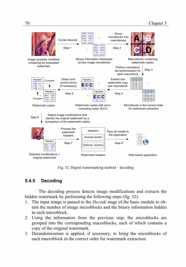
70 Chapter 5
Step 2
Detect image modifications and identify the original watermark by a
comparison of the watermark copies
Watermark copies with error-correcting codes (ECC)
Watermark copies
Step 5
Pass all results to the application
Step 6
Step 7
Group microblocks into
macroblocks
Step 4
Step 8
Image (possibly modified) containing an embedded
watermark
Invoke Decode
Step 1 ...
...
Binary information distributed across image microblocks
Macroblocks containing watermark copies
23 24 21 30 23 45 36 34
14
18
10
34
44
33
34
16 18 32 45 34 33 32
15 20 20 33 36 31 23
12 22 56 35 37 39 30
35 36 0 34 40 39 38
40 29 56 38 50 43 40
32 23 45 34 5 56 48
31 18 31 30 23 34 20
A BC D
1 2 3 4
16128
1514106
1395
117
Perform microblock de-randomization for
each macroblockStep 3
Microblocks in the correct order for watermark extraction
Extract one watermark copy per macroblock
Detect and correct errors(if necessary)
Detected modifications + original watermark
E C C...
...Compare
Compare
Headers
E C CHeadersHeaders
Headers
Headers
Headers
General section
Optional sections
Watermark headers
Process the watermark headers
1 2 3 4
16128
1514106
1395
117...
...
Web-based application
Fig. 32. Digital watermarking method – decoding
5.4.5 Decoding
The decoding process detects image modifications and extracts the hidden watermark by performing the following steps (fig. 32): 1. The input image is passed to the Decode stage of the basic module to ob-
tain the number of image microblocks and the binary information hidden in each microblock.
2. Using the information from the previous step, the microblocks are grouped into the corresponding macroblocks, each of which contains a copy of the original watermark.
3. Derandomization is applied, if necessary, to bring the microblocks of each macroblock in the correct order for watermark extraction.

Extendable data hiding methods 71
4. The watermark copies embedded into each macroblock are extracted. 5. If necessary, the error-correcting algorithm described in section 5.3.2 is
applied to each watermark copy to recover minor errors. 6. The resulting watermark copies are compared to each other in order to
detect any modified microblocks as well as to identify the watermark originally encoded into the image (see section 5.4.3).
7. Any existing watermark headers are processed in order to obtain addi-tional information related to the watermark.
8. The coordinates of any detected modified image microblocks, the binary watermark and the information obtained from the watermark headers are passed to the calling application for saving and/or further processing.
5.4.6 Conclusion
The digital watermarking method combines a sophisticated applica-tion-specific module with the basic module presented in section 5.2. The ap-plication-specific module handles the watermark headers, the manipulation of any necessary error-correcting codes and the processing of the image macroblocks. The amount of embeddable information is small but several new data hiding features are provided in addition to the robustness against JPEG transformations provided by the basic module. The new features – the detection of modified image areas and the reliable recovery of the embedded watermark – make the method suitable for scenarios needing a combination of multimedia authentication with proof of ownership or fingerprinting (see section 1.4).
One of the major advantages of the watermarking method is that it not only confirms the presence of a specified watermark but it can extract the exact watermark from the image provided that the image modifications are not too severe. This property of the method allows for maximum flexibility in its practical applications as the only information the decoder needs to read the watermark is the image itself.
Another important advantage is the usage of user-defined binary wa-termarks. They may contain arbitrary information, which is appropriate for the particular application without interfering with the functionality of the method.
In addition, the method enjoys the benefits of its modular structure – encapsulation, easy support and the possibility for enhancement by adding new features without affecting the existing functionality.

72
Chapter 6 A sample .NET implementation
As a prerequisite for performing tests and validating the functionality of the proposed methods, an implementation based on the .NET framework has been chosen. The framework offers several distinct advantages, which facilitate the development process [92], [93], [94]: 1. Several popular languages such as C/C++, C# and Visual Basic can be
mixed and used together. 2. An excellent debugger is present, which is a necessity when errors in the
data hiding methods are traced. 3. Extensive libraries offering standardized functions and programming
structures facilitate the development. 4. Web-relevant communication by means of web services, TCP or UDP
sockets, and HTTP or FTP clients can be implemented easily as the framework takes care of all low-level communication details.
5. Easy integration with other Microsoft technologies and portability to other operating systems [95] .
These advantages make the .NET framework a good choice for the creation of data hiding prototypes and for the verification of their functional-ity in different web-related contexts.
In the next sections, the architecture of the implemented methods is presented along with some details regarding the most important classes and modules.
6.1 Architectural overview
The implementation of the modular data hiding methods has the ar-chitecture presented in fig. 33. The functionality is divided into a data layer, a basic logic layer, an application-specific logic layer and a user interface layer. In addition, several classes belonging to different layers are grouped into a separate namespace called Utilities. They enhance the built-in .NET libraries.

A sample .NET implementation 73
The data layer contains all functions related to data I/O and basic data management. It contains the definitions of two new data types and provides various data conversion features.
Data layer
User intefrace layer
Bitstream management
Utilities
File I/O
Data conversionMatrix
management
Randomgenerator
JPEG processing
Basic logic layer
Application-specific logic layer
Basic module 1: JPEG DCTHiderEngine
Application-specific steganographic module
StegoHider
Basic module 2: BMP LSBHiderEngine Basic Module k
Application-specificdigital watermarking module
WatermarkHider
Orchestrator engine
GUI interface Command-line interface
Web service interface
Image transformations
Debugging
Headerprocessing
...
...
Fig. 33. Implementation – architectural overview
The basic logic layer contains the low-level data hiding logic corre-sponding to the basic module of each data hiding method. This logic encap-sulates all method features related to a specific target image format (in this case JPEG).
The application-specific logic layer contains the application-specific modules of the data hiding method as well as the orchestrator engine. The application-specific modules are responsible for the provision of high-level method features related to a concrete application area. The orchestrator en-gine assembles different data hiding methods by combining the correspond-ing basic and application-specific modules, which provide the desired meth-od features.
The user interface layer provides means for communication between an end user or an external application and the modular data hiding methods.
74 Chapter 6
It sets any necessary data hiding parameters, starts and stops the methods and consumes the end results of the data hiding procedures.
As shown in fig. 33, the classes of the upper layers use the function-ality provided by the classes of the lower layers. On the borders between the layers interactions take place: the upper layers pass parameters to the lower layers and process the obtained results. The interactions between the applica-tion-specific logic layer, the basic logic layer and the data layer lead to the implementation of the discussed data hiding methods. The interactions be-tween the user-interface layer and the application-specific logic layer are re-sponsible for the communication with these methods.
The next sections describe the Utilities namespace and each layer in detail.
6.2 Utilities
The classes belonging to the Utilities namespace provide some basic functions which are not part of the .NET framework but are needed for the implementation of the modular data hiding methods. They should be acces-sible throughout the application.
The Data conversion class provides sophisticated array conversion and substitution procedures. Furthermore, type conversion functions support-ing overflow detection are present as well as some basic mathematical func-tions, which provide enhanced control over the rounding of scalar values.
The File I/O class handles all file operations. It processes the reading and writing of image files and provides functions for file type recognition and file comparison. In addition, the class supports the downloading of files from a specified Internet URL address, which is a necessity for the usage of the methods in a web-based environment.
The Debugging class contains functions for array and matrix compar-ison, which facilitate the tracing of errors in the data hiding methods. The class determines the location and magnitude of any discrepancies between arrays or matrices which should be identical.
The JPEG processing class encapsulates some low-level functions which pertain to the JPEG image format. The class performs JPEG-related color-space transformations and calculates the discrete cosine transform. Furthermore, it analyzes the image blocks, which constitute the JPEG image. It returns their number and their corresponding DCT values at chosen stages of the JPEG compression or decompression process (for detailed in-formation about the JPEG compression method see section 5.2.2).

A sample .NET implementation 75
The Random generator class contains an implementation of a pseu-do-random generator. It provides the means of generating the permutations necessary for the randomization of the image blocks (see section 5.3.3). As a general utility class, it can be used to generate any pseudo-random integer, floating-point or Boolean values.
The Image transformations class contains various image-to-array and array-to-image transformations as well as several color-space transfor-mations and image analysis functions. The class converts arbitrary .NET im-age objects to two-dimensional arrays, and vice-versa. The arrays contain a representation of the image in a specified-color space. They are necessary because the .NET framework has its own image objects which encapsulate the image information. These objects facilitate the high-level usage of the image in the user interface layer but they are not suitable for the low-level image processing tasks performed by the data hiding methods.
6.3 Data layer
The data layer contains two classes: the Bitstream management class and the Matrix management class. Both of them were created to facilitate the handling of two data types necessary for the implementation of the data hid-ing methods: bit-streams and matrices.
Bit-streams are not well-supported by the .NET framework. The basic unit of the streams provided by the .NET framework is usually a byte or a Unicode character and they enable the processing of binary or text files, which are to be saved or transmitted over the Internet. In data hiding such a basic unit is too large due to several reasons: 1. The amount of available space, which can be used for data hiding, is very
limited. If the headers and the embedded information have to be aligned on byte boundaries, the accumulated loss could reach up to a dozen bytes, which is undesirable – especially for digital watermarking meth-ods.
2. The use of error-correcting codes (see section 5.3.2) assumes that the in-formation, which the codes are applied to, consists of bits and not bytes or Unicode characters.
3. Often, a whole byte or a Unicode character cannot be hidden in a single image block. In such cases the byte or the character has to be split into bits that are distributed across several image blocks.
Consequently, the basic unit has to be decreased from a byte or a Unicode character to a bit. As the ordinary .NET streams do not support such a small basic unit, a new Bitstream management class was created for that
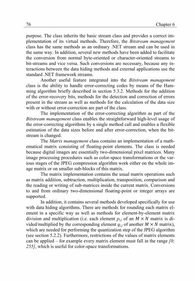
76 Chapter 6
purpose. The class inherits the basic stream class and provides a correct im-plementation of its virtual methods. Therefore, the Bitstream management class has the same methods as an ordinary .NET stream and can be used in the same way. In addition, several new methods have been added to facilitate the conversion from normal byte-oriented or character-oriented streams to bit-streams and vice versa. Such conversions are necessary, because any in-teractions between the data hiding methods and external applications use the standard .NET framework streams.
Another useful feature integrated into the Bitstream management class is the ability to handle error-correcting codes by means of the Ham-ming algorithm briefly described in section 5.3.2. Methods for the addition of the error-recovery bits, methods for the detection and correction of errors present in the stream as well as methods for the calculation of the data size with or without error-correction are part of the class.
The implementation of the error-correcting algorithm as part of the Bitstream management class enables the straightforward high-level usage of the error-correcting algorithms by a single method call and enables a flexible estimation of the data sizes before and after error-correction, when the bit-stream is changed.
The Matrix management class contains an implementation of a math-ematical matrix consisting of floating-point elements. The class is needed because digital images are essentially two-dimensional pixel matrices. Many image processing procedures such as color-space transformations or the var-ious stages of the JPEG compression algorithm work either on the whole im-age matrix or on smaller sub-blocks of this matrix.
The matrix implementation contains the usual matrix operations such as matrix addition, subtraction, multiplication, transposition, comparison and the reading or writing of sub-matrices inside the current matrix. Conversions to and from ordinary two-dimensional floating-point or integer arrays are supported.
In addition, it contains several methods developed specifically for use with data hiding algorithms. There are methods for rounding each matrix el-ement in a specific way as well as methods for element-by-element matrix division and multiplication (i.e. each element pi,j of an matrix is di-vided/multiplied by the corresponding element qi,j of another matrix), which are needed for performing the quantization step of the JPEG algorithm (see section 5.2.2). Furthermore, restrictions of the values of matrix elements can be applied – for example every matrix element must fall in the range [0; 255], which is useful for color-space transformations.

A sample .NET implementation 77
Both new data types – matrices and bit-streams – are used by the basic and the application-specific logic layers to encapsulate critical low-level and computation-intensive operations. In this way, these data types re-duce the code complexity and increase the performance of the implemented modular data hiding methods.
6.4 Basic logic layer
The basic logic layer contains the different basic modules, which can be used as low-level modules in the data hiding algorithms. All basic mod-ules inherit the BaseHiderEngine abstract class and provide an implementa-tion of its public methods PrepareToEncode, FinishEncode and Decode (see section 5.1).
There are two different basic modules which are currently imple-mented: the DCTHiderEngine class and the LSBHiderEngine class. The DCTHiderEngine class contains the code of the basic module discussed in section 5.2, which is designed to work with JPEG images. The LSBHiderEn-gine class implements a basic module for use with BMP images or other un-compressed image formats.
The implementation of the basic modules revolves around the Pre-pareToEncode, FinishEncode and Decode methods. While the LSBHiderEn-gine is very straightforward and contains only a couple of bit-modification functions in addition to the three obligatory methods, the DCTHiderEngine is much more complex.
One reason for this complexity are the steps of the JPEG compres-sion algorithm, which have to be carried out by the code of the basic module up to the last lossy step described in section 5.2.2. As non-trivial mathemati-cal transformations are involved, there are several additional functions in the code devoted to the necessary calculations. They are heavily used in the PrepareToEncode method, which delivers the maximum amount of embed-dable bits per image block by analyzing the quantized DCT values of each image block.
Another factor, which significantly raises the complexity of the code, lies in the computations necessary to perform steps 1, 1 and 4 of the Fin-ishEncode stage described in section 5.2.3. They ensure the robustness against the different the different kinds of JPEG transformations (compres-sion, decompression and recompression) as well as the preservation of high image quality.
Each step is performed by two to three functions coordinated by the FinishEncode method under the additional constraints of minimizing the
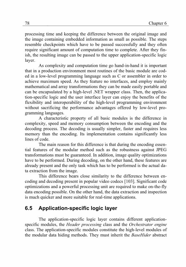
78 Chapter 6
processing time and keeping the difference between the original image and the image containing embedded information as small as possible. The steps resemble checkpoints which have to be passed successfully and they often require significant amount of computation time to complete. After they fin-ish, the resulting image can be passed to the upper application-specific logic layer.
As complexity and computation time go hand-in-hand it is important that in a production environment most routines of the basic module are cod-ed in a low-level programming language such as C or assembler in order to achieve maximum speed. As they feature no interfaces, and employ mainly mathematical and array transformations they can be made easily portable and can be encapsulated by a high-level .NET wrapper class. Then, the applica-tion-specific logic and the user interface layer can enjoy the benefits of the flexibility and interoperability of the high-level programming environment without sacrificing the performance advantages offered by low-level pro-gramming languages.
A characteristic property of all basic modules is the difference in complexity, speed and memory consumption between the encoding and the decoding process. The decoding is usually simpler, faster and requires less memory than the encoding. Its implementation contains significantly less lines of code.
The main reason for this difference is that during the encoding essen-tial features of the modular method such as the robustness against JPEG transformations must be guaranteed. In addition, image quality optimizations have to be performed. During decoding, on the other hand, these features are already present and the only task which has to be performed is the actual da-ta extraction from the image.
This difference bears close similarity to the difference between en-coding and decoding present in popular video codecs [103]. Significant code optimizations and a powerful processing unit are required to make on-the-fly data encoding possible. On the other hand, the data extraction and inspection is much quicker and more suitable for real-time applications.
6.5 Application-specific logic layer
The application-specific logic layer contains different application-specific modules, the Header processing class and the Orchestrator engine class. The application-specific modules constitute the high-level modules of the modular data hiding methods. They must inherit the BaseHider abstract
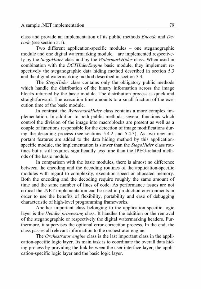
A sample .NET implementation 79
class and provide an implementation of its public methods Encode and De-code (see section 5.1).
Two different application-specific modules – one steganographic module and one digital watermarking module – are implemented respective-ly by the StegoHider class and by the WatermarkHider class. When used in combination with the DCTHiderEngine basic module, they implement re-spectively the steganographic data hiding method described in section 5.3 and the digital watermarking method described in section 5.4.
The StegoHider class contains only the obligatory public methods which handle the distribution of the binary information across the image blocks returned by the basic module. The distribution process is quick and straightforward. The execution time amounts to a small fraction of the exe-cution time of the basic module.
In contrast, the WatermarkHider class contains a more complex im-plementation. In addition to both public methods, several functions which control the division of the image into macroblocks are present as well as a couple of functions responsible for the detection of image modifications dur-ing the decoding process (see sections 5.4.2 and 5.4.3). As two new im-portant features are added to the data hiding method by this application-specific module, the implementation is slower than the StegoHider class rou-tines but it still requires significantly less time than the JPEG-related meth-ods of the basic module.
In comparison with the basic modules, there is almost no difference between the encoding and the decoding routines of the application-specific modules with regard to complexity, execution speed or allocated memory. Both the encoding and the decoding require roughly the same amount of time and the same number of lines of code. As performance issues are not critical the .NET implementation can be used in production environments in order to use the benefits of flexibility, portability and ease of debugging characteristic of high-level programming frameworks.
Another important class belonging to the application-specific logic layer is the Header processing class. It handles the addition or the removal of the steganographic or respectively the digital watermarking headers. Fur-thermore, it supervises the optional error-correction process. In the end, the class passes all relevant information to the orchestrator engine.
The Orchestrator engine class is the last important class in the appli-cation-specific logic layer. Its main task is to coordinate the overall data hid-ing process by providing the link between the user interface layer, the appli-cation-specific logic layer and the basic logic layer.

80 Chapter 6
The engine provides access to the most important data hiding param-eters such as the maximum JPEG compression ratio tolerable by the DCTHiderEngine and the optional usage of error-correcting codes (see sec-tion 5.3.2). Furthermore, it selects a suitable combination of a basic module and an application-specific module based on the usage preferences indicated by the corresponding user interface. It also synchronizes the header pro-cessing with the actual data hiding encoding or decoding process. In the end, it passes the results of the data hiding routines in a suitable format back to the user interface layer.
6.6 User interface layer
The user interface layer provides the connection between the data hiding methods and any external applications or human users. There are dif-ferent types of interfaces adequate for the different kinds of applications and application areas: stand-alone applications may profit from a Graphical User Interface (GUI) or a command-line interface while web-oriented applications may need a web service interface.
The interfaces which are currently implemented consist of a standard GUI for standalone interactive use by a human user, a GUI enabling the start and the analysis of batch jobs and a web service interface suitable for usage in web-based scenarios.
6.6.1 Standard interactive GUI
The standard interactive GUI is shown in fig. 34. The user can see the processed image before and after each data hiding procedure in the main application panel. He or she can initiate actions by means of the program menus or the toolbar at the top area of the application window. After the ini-tiation and the completion of each action as well as in the case of a possible problem, the status panel at the bottom left part of the application window shows brief information describing the success or the failure of the action. The progress bar at the bottom right part of the application window can be used to show the progress of longer data hiding operations.
The program menus belonging to the standard GUI are shown in de-tails in fig. 35. The File menu contains the usual open, save and exit actions as well as links to the GUIs responsible for the processing of batch jobs. The View menu contains a command for showing image modifications discov-ered by the modular digital watermarking method. The Stego menu is re-sponsible for the start of steganographic data hiding by means of either the
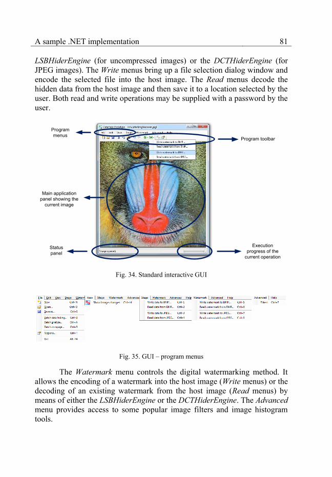
A sample .NET implementation 81
LSBHiderEngine (for uncompressed images) or the DCTHiderEngine (for JPEG images). The Write menus bring up a file selection dialog window and encode the selected file into the host image. The Read menus decode the hidden data from the host image and then save it to a location selected by the user. Both read and write operations may be supplied with a password by the user.
Main application panel showing the
current image
Execution progress of the
current operation
Status panel
Program toolbar
Program menus
Fig. 34. Standard interactive GUI
Fig. 35. GUI – program menus
The Watermark menu controls the digital watermarking method. It allows the encoding of a watermark into the host image (Write menus) or the decoding of an existing watermark from the host image (Read menus) by means of either the LSBHiderEngine or the DCTHiderEngine. The Advanced menu provides access to some popular image filters and image histogram tools.

82 Chapter 6
The Options command in the File menu displays the dialog window shown in fig. 36. It controls some important data hiding settings. The Stego and Watermark sections have an identical layout. The Use error correction setting controls whether error-correcting codes are used. The Save file name setting specifies whether the data file name is added to the file headers (see section 5.3.1). The Content encryption setting controls the optional encryp-tion algorithm for the embedded data. The Secure data hiding setting gov-erns the use of pseudo-random generators during the data embedding and extraction. The Resistant to JPEG compression down to setting represents the maximum JPEG compression level, for which the DCTHiderEngine guarantees robustness of the embedded data. The Save JPEG files to disk with a quality of represents the JPEG compression level used by the program to save images in the JPEG file format.
Fig. 36. GUI – dialog window Options
6.6.2 Batch jobs
The batch jobs are handled by a GUI which consists of two forms – one form which is responsible for the controlling of the batch processing it-self and one form which contains tools for multiple file comparison used for the evaluation of the modular data hiding methods.
The form controlling the batch processing is presented in fig. 37. The Image folder contains the host images to be processed. The Data folder spec-ifies the location of the data files. During encoding, the batch algorithm em-beds each data file from the Data folder into each image from the Image folder and saves the resulting image file into the Result image folder. If there are M images in the Image folder and N files in the Data folder, the number of possible combinations between them – and therefore the number of output images generated by the data hiding method and saved in the Result image folder – is equal to .
During decoding, the batch algorithm processes each image con-tained in the Image folder and saves the extracted data file in the Data fold-
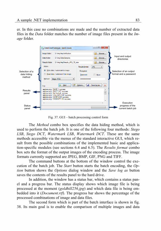
A sample .NET implementation 83
er. In this case no combinations are made and the number of extracted data files in the Data folder matches the number of image files present in the Im-age folder.
Execution progress of the
current batch job
Resultspanel
Selection of an outputformat and a password
Input and outputdirectories
Statuspanel
Selection of adata hIding
method
Fig. 37. GUI – batch processing control form
The Method combo box specifies the data hiding method, which is used to perform the batch job. It is one of the following four methods: Stego LSB, Stego DCT, Watermark LSB, Watermark DCT. These are the same methods accessible via the menus of the standard interactive GUI, which re-sult from the possible combinations of the implemented basic and applica-tion-specific modules (see sections 6.4 and 6.5). The Results format combo box sets the format of the output images of the encoding process. The image formats currently supported are JPEG, BMP, GIF, PNG and TIFF.
The command buttons at the bottom of the window control the exe-cution of the batch job. The Start button starts the batch encoding, the Op-tion button shows the Options dialog window and the Save log as button saves the contents of the results panel to the hard drive.
In addition, the window has a status bar, which contains a status pan-el and a progress bar. The status display shows which image file is being processed at the moment (goldhill256.jpg) and which data file is being em-bedded into it (Document.rtf). The progress bar shows the percentage of the processed combinations of image and data files.
The second form which is part of the batch interface is shown in fig. 38. Its main goal is to enable the comparison of multiple images and data
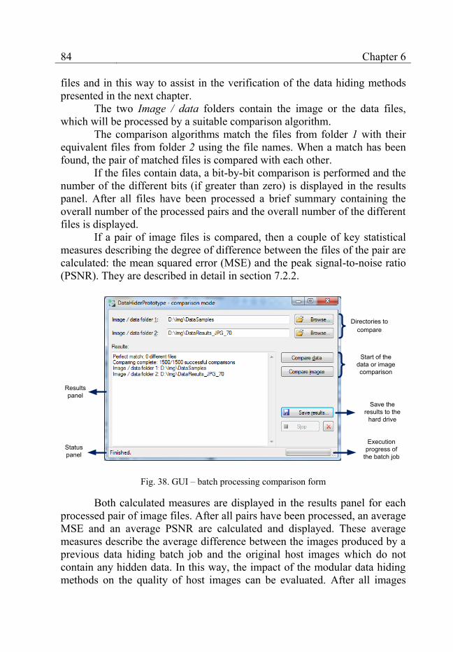
84 Chapter 6
files and in this way to assist in the verification of the data hiding methods presented in the next chapter.
The two Image / data folders contain the image or the data files, which will be processed by a suitable comparison algorithm.
The comparison algorithms match the files from folder 1 with their equivalent files from folder 2 using the file names. When a match has been found, the pair of matched files is compared with each other.
If the files contain data, a bit-by-bit comparison is performed and the number of the different bits (if greater than zero) is displayed in the results panel. After all files have been processed a brief summary containing the overall number of the processed pairs and the overall number of the different files is displayed.
If a pair of image files is compared, then a couple of key statistical measures describing the degree of difference between the files of the pair are calculated: the mean squared error (MSE) and the peak signal-to-noise ratio (PSNR). They are described in detail in section 7.2.2.
Execution progress of
the batch jobStatuspanel
Start of thedata or image comparison
Resultspanel
Directories to compare
Save the results to the
hard drive
Fig. 38. GUI – batch processing comparison form
Both calculated measures are displayed in the results panel for each processed pair of image files. After all pairs have been processed, an average MSE and an average PSNR are calculated and displayed. These average measures describe the average difference between the images produced by a previous data hiding batch job and the original host images which do not contain any hidden data. In this way, the impact of the modular data hiding methods on the quality of host images can be evaluated. After all images
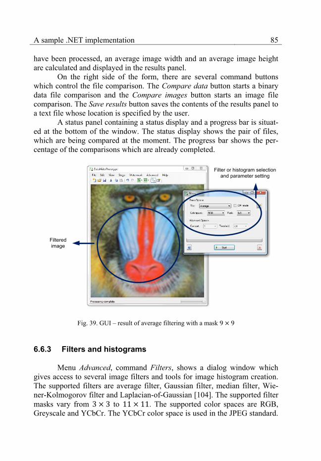
A sample .NET implementation 85
have been processed, an average image width and an average image height are calculated and displayed in the results panel.
On the right side of the form, there are several command buttons which control the file comparison. The Compare data button starts a binary data file comparison and the Compare images button starts an image file comparison. The Save results button saves the contents of the results panel to a text file whose location is specified by the user.
A status panel containing a status display and a progress bar is situat-ed at the bottom of the window. The status display shows the pair of files, which are being compared at the moment. The progress bar shows the per-centage of the comparisons which are already completed.
Filteredimage
Filter or histogram selection and parameter setting
Fig. 39. GUI – result of average filtering with a mask
6.6.3 Filters and histograms
Menu Advanced, command Filters, shows a dialog window which gives access to several image filters and tools for image histogram creation. The supported filters are average filter, Gaussian filter, median filter, Wie-ner-Kolmogorov filter and Laplacian-of-Gaussian [104]. The supported filter masks vary from to . The supported color spaces are RGB, Greyscale and YCbCr. The YCbCr color space is used in the JPEG standard.
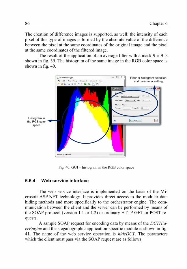
86 Chapter 6
The creation of difference images is supported, as well: the intensity of each pixel of this type of images is formed by the absolute value of the difference between the pixel at the same coordinates of the original image and the pixel at the same coordinates of the filtered image.
The result of the application of an average filter with a mask is shown in fig. 39. The histogram of the same image in the RGB color space is shown in fig. 40.
Histogram in the RGB color
space
Filter or histogram selection and parameter setting
Fig. 40. GUI – histogram in the RGB color space
6.6.4 Web service interface
The web service interface is implemented on the basis of the Mi-crosoft ASP.NET technology. It provides direct access to the modular data hiding methods and more specifically to the orchestrator engine. The com-munication between the client and the server can be performed by means of the SOAP protocol (version 1.1 or 1.2) or ordinary HTTP GET or POST re-quests.
A sample SOAP request for encoding data by means of the DCTHid-erEngine and the steganographic application-specific module is shown in fig. 41. The name of the web service operation is hideDCT. The parameters which the client must pass via the SOAP request are as follows:

A sample .NET implementation 87
<?xml version="1.0" encoding="utf-8"?>
<soap:Envelope
xmlns:xsi="http://www.w3.org/2001/XMLSchema-instance"
xmlns:xsd="http://www.w3.org/2001/XMLSchema"
xmlns:soap="http://schemas.xmlsoap.org/soap/envelope/">
<soap:Body>
<hideDCT xmlns="http://ilchev.net">
<sourceImage>base64Binary</sourceImage>
<destinationImageFormat>JPG or BMP
</destinationImageFormat>
<informationToHide>base64Binary</informationToHide>
<errorCorrection>Boolean</errorCorrection>
<saveFileName>Boolean</saveFileName>
<dataStreamFileName>string</dataStreamFileName>
<withstandJPEGCompressionRatio>unsignedByte
</withstandJPEGCompressionRatio>
</hideDCT>
</soap:Body>
</soap:Envelope>
Fig. 41. A sample SOAP request
1. sourceImage: the host image itself (encoded in the base64 format); 2. destinationImageFormat: the image format of the result (currently either
JPG or BMP); 3. informationToHide: the binary data which will be embedded (also en-
coded in the base64 format); 4. errorCorrection: a Boolean value controlling the optional usage of error-
correction: true if the error-correction is enabled and false if the error-correction is disabled;
5. saveFileName: a Boolean value controlling whether the name of the file containing the binary data is included in the headers: true if it is included and false otherwise;
6. dataStreamFileName: the name of the file containing the binary data (as a string). This parameter is not used if saveFileName (parameter 4) is set to false;
7. withstandJPEGCompressionRatio: the maximum JPEG compression ra-tio which can be applied to the result – the image containing hidden in-formation – without destroying the embedded data.
A sample response to the SOAP request is presented in fig. 42. The response delivers the image containing the embedded data back to the client.

88 Chapter 6
A useful alternative to SOAP is the HTTP POST request (fig. 43). In-stead of using a SOAP envelope, the necessary parameters are passed to the web service interface in the form of an ordinary HTTP POST request. This alternative simplifies the creation of the request. It is convenient for use if no libraries providing SOAP support are present on the client side – for example if the client consists of a JavaScript code running in a browser environment.
<?xml version="1.0" encoding="utf-8"?>
<soap:Envelope
xmlns:xsi="http://www.w3.org/2001/XMLSchema-instance"
xmlns:xsd="http://www.w3.org/2001/XMLSchema"
xmlns:soap="http://schemas.xmlsoap.org/soap/envelope/">
<soap:Body>
<hideDCTResponse xmlns="http://ilchev.net">
<hideDCTResult>base64Binary</hideDCTResult>
</hideDCTResponse>
</soap:Body>
</soap:Envelope>
Fig. 42. A sample SOAP response
POST /StegiWeb/StegiWeb.asmx/hideDCT HTTP/1.1
Host: xxx.xxx.xxx.xxx
Content-Type: application/x-www-form-urlencoded
Content-Length: length
sourceImage=string&destinationImageFormat=string&
informationToHide=string&informationToHide=string&
errorCorrection=string&saveFileName=string&
dataStreamFile-
Name=string&withstandJPEGCompressionRatio=string
Fig. 43. A sample HTTP POST request
The response to the sample HTTP POST request is shown in fig. 44. The base64Binary XML element contains the resulting image. A similar re-quest and response handle the data decoding process (the web service opera-tion is named unHideDCT). In addition, there is a pair of web service opera-tions (hideLSB and unHideLSB) enabling the access to the steganographic
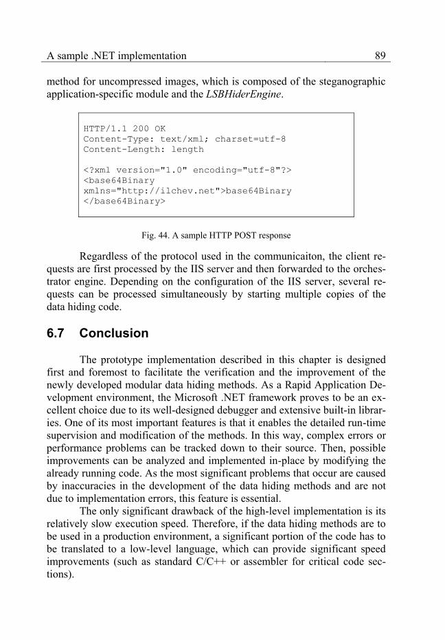
A sample .NET implementation 89
method for uncompressed images, which is composed of the steganographic application-specific module and the LSBHiderEngine.
HTTP/1.1 200 OK
Content-Type: text/xml; charset=utf-8
Content-Length: length
<?xml version="1.0" encoding="utf-8"?>
<base64Binary
xmlns="http://ilchev.net">base64Binary
</base64Binary>
Fig. 44. A sample HTTP POST response
Regardless of the protocol used in the communicaiton, the client re-quests are first processed by the IIS server and then forwarded to the orches-trator engine. Depending on the configuration of the IIS server, several re-quests can be processed simultaneously by starting multiple copies of the data hiding code.
6.7 Conclusion
The prototype implementation described in this chapter is designed first and foremost to facilitate the verification and the improvement of the newly developed modular data hiding methods. As a Rapid Application De-velopment environment, the Microsoft .NET framework proves to be an ex-cellent choice due to its well-designed debugger and extensive built-in librar-ies. One of its most important features is that it enables the detailed run-time supervision and modification of the methods. In this way, complex errors or performance problems can be tracked down to their source. Then, possible improvements can be analyzed and implemented in-place by modifying the already running code. As the most significant problems that occur are caused by inaccuracies in the development of the data hiding methods and are not due to implementation errors, this feature is essential.
The only significant drawback of the high-level implementation is its relatively slow execution speed. Therefore, if the data hiding methods are to be used in a production environment, a significant portion of the code has to be translated to a low-level language, which can provide significant speed improvements (such as standard C/C++ or assembler for critical code sec-tions).

90
Chapter 7 Verification and evaluation
In this chapter, the verification and the evaluation of the extendable modular data hiding methods are discussed. Several verification procedures and the analysis of the results obtained from them are presented in detail. In addition, the performance of statistical steganalysis tests for the detection of embedded data is examined.
The verification of the modular data hiding methods is designed to enable their evaluation according to the triangle of criteria shown in fig. 45.
Image quality
Data quantity Number of method features(evaluation function)
Fig. 45. Evaluation criteria
The triangle depicts the three most important criteria, which charac-terize every data hiding method. The image quality represents how similar the images before and after data embedding are. Less similarity is equal to lower image quality and vice versa. The data quantity measures the amount of data that can be embedded in the host image. The method features include the extensibility of the methods, the robustness against JPEG modifications, the arbitrariness of the data and the ability to detect the regions of unauthor-ized image modifications (see chapter 2 and chapter 5).
There is a trade-off between the three criteria. They cannot be simul-taneously maximized. For example, if more data has to be embedded, either the image deteriorates or some method features have to be sacrificed. An ad-ditional method feature (such as the detection of image modifications in the

Verification and evaluation 91
digital watermarking method) leads to a decrease in the quantity of embed-dable data or a decrease in the image quality.
When data hiding methods are evaluated, these trade-offs have to be taken into consideration. Different application scenarios have different re-quirements, as well, which means that there is no universal data hiding method suitable for all possible applications. For each application scenario, the trade-offs have to be adjusted in such a way, as to maximize the value of the data hiding method for the concrete application. The adjustments often necessitate changes in the methods themselves and this is one of the main reasons why the extensibility of the modular data hiding methods is so im-portant for their practical application.
7.1 Verification samples
The verification is based on testing the functionality of the methods on specially selected image and data samples. The samples are chosen in such a way, that they cover a wide range of possible combinations between image and data. The image samples are common for all tests and are de-scribed in section 7.1.1. The data samples, which are embedded into the im-age samples, are different for the steganographic method and for the digital watermarking method. They are described in detail in section 7.1.1.
Lena Digital color photo
Grey-level scanned photo
Color cartoon Scanned color text
Fig. 46. Image samples
7.1.1 Image samples
Common for all verification procedures are the 76 host image sam-ples which consist of standard test images such as Lena, photos made by a digital camera, logos, cartoons, scanned photos, and scanned text pages. Color, greyscale and black-and-white images are represented, as well as dif-ferent image formats: BMP, JPEG, PNG, GIF and TIFF. In addition, differ-ent types of color transitions and textures are present in each chosen sample.
92 Chapter 7
An excerpt of the host image samples is shown in fig. 46. The modu-lar data hiding methods must be capable of processing all image samples successfully. The wide variety of the samples ensures the applicability of the methods on most common image types and in most application areas.
7.1.2 Data samples
The data samples used for verification are different for the different methods due to the difference in the maximum embeddable data quantity. The steganographic method provides higher capacity and therefore the data samples consist of 20 binary and textual files with sizes ranging from several bytes to several kilobytes. The data samples used with the digital watermark-ing method consist of 10 textual watermarks with sizes ranging from 2 bytes to 70 bytes.
The variety of the data samples ensures that the data hiding methods perform reliably on arbitrary data. In combination with the image samples presented in the previous section the tests of the steganographic method cov-er image-data pairs and the tests of the digital watermark-ing method work on image-data pairs. The exact verification procedures are described in the following section.
7.2 Verification procedures
The verification procedures consist of testing the features provided by the modular data hiding methods and measuring the resulting image qual-ity. The most important feature test relates to the robustness against JPEG transformations provided by the DCTHiderEngine basic module. The image quality tests consist of calculating the MSE and PSNR measures presented in section 7.2.2. The steganographic method and the digital watermarking method are tested separately.
The tests are performed by means of the batch processing control form and the batch processing analysis form presented correspondingly in fig. 37 and fig. 38. All possible combinations between the selected image and the data samples are verified by forming an image-data pair for each combination. After all image-data pairs have been processed by the verifica-tion procedures, the obtained results can be used for the evaluation of the modular data hiding methods.

Verification and evaluation 93
7.2.1 JPEG robustness verification
The robustness against various JPEG transformations is the core fea-ture provided by the DCTHiderEngine. To motivate the need for it, we will show briefly that the data embedded into JPEG images with a compression ratio of 70 is not robust against JPEG decompression without first applying the method described in section 5.2.4.
We consider the coefficients datalk ZlkC ),(|, and datalk ZlkC ),(|)1(,
as they are defined at stages 0 and 2 of the algorithmic description in section 5.2.4. An average of about 99.75% of all )1(
,lkC are identical to lkC , . If we as-sume uniform probability distributions, this corresponds to about 99.875% of incorrect bits on average. It is important to point out that one change in the pixel values of a given DCT block after decompression may affect all DCT coefficients of the block. If this happens, then all data bits embedded into this block are changed more or less randomly. As a consequence, several da-ta changes may occur in close proximity to each other, which makes the use of error-correcting codes ineffective. The above percentage corresponds to an average of 1.25 bits changed for every 1000 bits, which is not enough for the reliable recovery of cryptographic signatures. The method described in section 5.2.4 solves this problem.
Its functionality is tested by three verification procedures. They have a similar structure consisting of a sequence of 4 steps. Steps 1 to 2 differ slightly for each procedure and are handled by the batch processing control form. Step 3 is identical for all procedures. It is performed by the batch pro-cessing analysis form.
The first verification procedure tests the robustness against JPEG compression by performing the following steps on each image-data pair: 1. Embed the data or the watermark into the image and save the resulting
image in BMP format. 2. Compress the image in JPEG by means of an external image processing
program using an arbitrary JPEG quality ratio , where q is the pre-determined JPEG quality factor specified in the Options program menu of the GUI.
3. Extract the data or the watermark from the compressed image and save it to a file.
4. Compare the original data or watermark with the extracted one and, if they are not identical, print the number of different bits in the results panel of the batch processing analysis form.
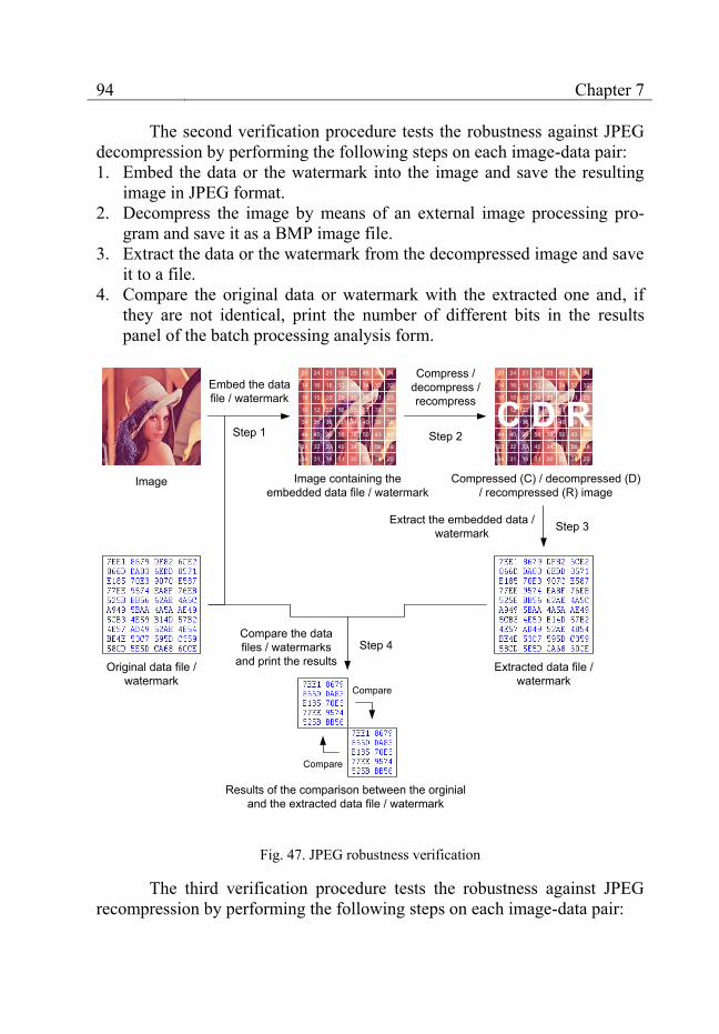
94 Chapter 7
The second verification procedure tests the robustness against JPEG decompression by performing the following steps on each image-data pair: 1. Embed the data or the watermark into the image and save the resulting
image in JPEG format. 2. Decompress the image by means of an external image processing pro-
gram and save it as a BMP image file. 3. Extract the data or the watermark from the decompressed image and save
it to a file. 4. Compare the original data or watermark with the extracted one and, if
they are not identical, print the number of different bits in the results panel of the batch processing analysis form.
Original data file / watermark
Image
23 24 21 30 23 45 36 34
14
18
10
34
44
33
34
16 18 32 45 34 33 32
15 20 20 33 36 31 23
12 22 56 35 37 39 30
35 36 0 34 40 39 38
40 29 56 38 50 43 40
32 23 45 34 5 56 48
31 18 31 30 23 34 20
Embed the data file / watermark
Step 1
Image containing the embedded data file / watermark
Extracted data file / watermark
23 24 21 30 23 45 36 34
14
18
10
34
44
33
34
16 18 32 45 34 33 32
15 20 20 33 36 31 23
12 22 56 35 37 39 30
35 36 0 34 40 39 38
40 29 56 38 50 43 40
32 23 45 34 5 56 48
31 18 31 30 23 34 20
Compress / decompress / recompress
Step 2
Compressed (C) / decompressed (D)/ recompressed (R) image
C D R
Step 3Extract the embedded data / watermark
Results of the comparison between the orginial and the extracted data file / watermark
Compare
Compare
Compare the data files / watermarks
and print the resultsStep 4
Fig. 47. JPEG robustness verification
The third verification procedure tests the robustness against JPEG recompression by performing the following steps on each image-data pair:
Verification and evaluation 95
1. Embed the data or the watermark into the image and save the resulting image in JPEG.
2. Recompress the image in JPEG by means of an external image pro-cessing program using an arbitrary JPEG quality ratio , where q is the predetermined JPEG quality factor specified in the Options program menu of the GUI.
3. Extract the data or the watermark from the recompressed image and save it to a file.
4. Compare the original data or watermark with the extracted one and, if they are not identical, print the number of different bits in the results panel of the batch processing analysis form.
The steps of the three verification procedures are summarized in fig. 47. All three procedures deliver as an end result the number of the extracted data files or watermarks which are different from their originals. Then, this number is divided by the total number of image-data pairs and the resulting fraction is used in the evaluation of the data hiding methods. The result of the verification (in %) is defined as:
(
) .
In the ideal case, all extracted data files or watermarks are identical
to the originals leading to zero differences. The verification result is equal to 100% and the verification is passed successfully.
In case of differences, the verification result is less than 100%. In general, such a result leads to a verification failure. The data hiding methods have to be reworked to eliminate the causes of the differences.
7.2.2 Image quality verification
The procedure for image quality verification measures the degree of difference between the original image file and the image file after data hid-ing for each image-data pair. Small differences are an indication for good image quality while large differences indicate an undesirable loss in quality, which may be perceptible for the end user.
An estimation of the image differences can be made by means of the following key statistical measures: the mean squared error (MSE) and the peak signal-to-noise ratio (PSNR) [105]. Both measures summarize the dif-ferences between two images into a single numerical value and are important criteria for the optimization and the evaluation of the new data hiding meth-
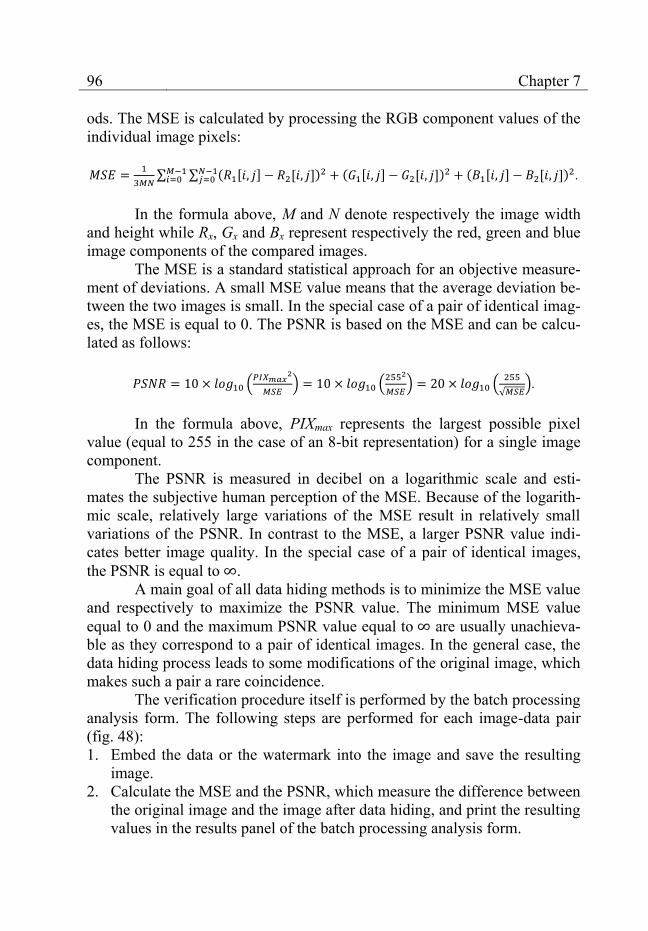
96 Chapter 7
ods. The MSE is calculated by processing the RGB component values of the individual image pixels:
∑ ∑ ( [ ] [ ])
( [ ] [ ]) ( [ ] [ ])
.
In the formula above, M and N denote respectively the image width
and height while Rx, Gx and Bx represent respectively the red, green and blue image components of the compared images.
The MSE is a standard statistical approach for an objective measure-ment of deviations. A small MSE value means that the average deviation be-tween the two images is small. In the special case of a pair of identical imag-es, the MSE is equal to 0. The PSNR is based on the MSE and can be calcu-lated as follows:
(
) (
) (
√ ).
In the formula above, PIXmax represents the largest possible pixel
value (equal to 255 in the case of an 8-bit representation) for a single image component.
The PSNR is measured in decibel on a logarithmic scale and esti-mates the subjective human perception of the MSE. Because of the logarith-mic scale, relatively large variations of the MSE result in relatively small variations of the PSNR. In contrast to the MSE, a larger PSNR value indi-cates better image quality. In the special case of a pair of identical images, the PSNR is equal to .
A main goal of all data hiding methods is to minimize the MSE value and respectively to maximize the PSNR value. The minimum MSE value equal to 0 and the maximum PSNR value equal to are usually unachieva-ble as they correspond to a pair of identical images. In the general case, the data hiding process leads to some modifications of the original image, which makes such a pair a rare coincidence.
The verification procedure itself is performed by the batch processing analysis form. The following steps are performed for each image-data pair (fig. 48): 1. Embed the data or the watermark into the image and save the resulting
image. 2. Calculate the MSE and the PSNR, which measure the difference between
the original image and the image after data hiding, and print the resulting values in the results panel of the batch processing analysis form.
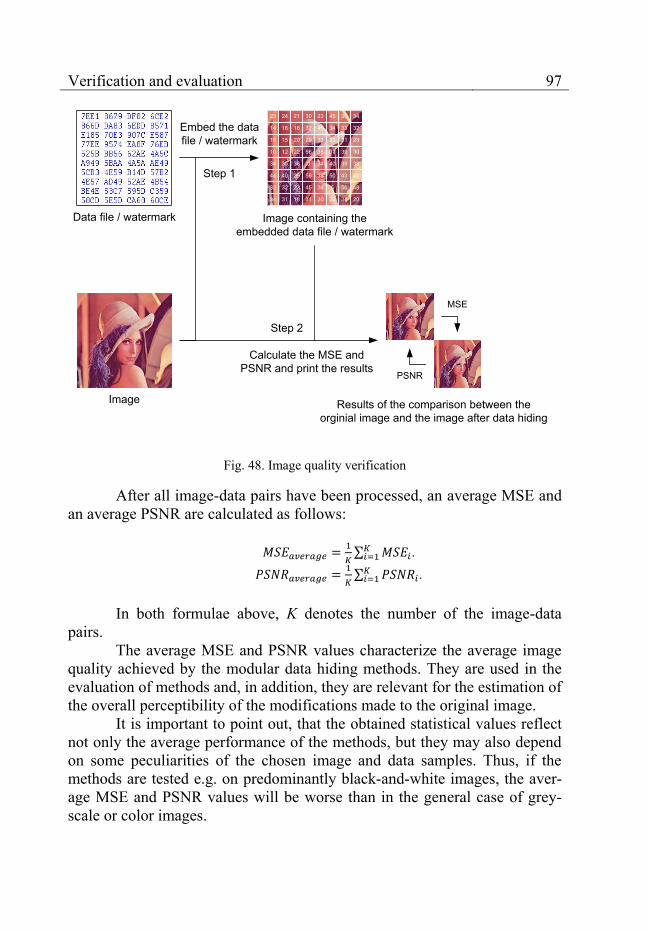
Verification and evaluation 97
Data file / watermark
Image
Embed the data file / watermark
Step 1
Image containing the embedded data file / watermark
Results of the comparison between the orginial image and the image after data hiding
MSE
PSNR
Calculate the MSE and PSNR and print the results
Step 2
23 24 21 30 23 45 36 34
14
18
10
34
44
33
34
16 18 32 45 34 33 32
15 20 20 33 36 31 23
12 22 56 35 37 39 30
35 36 0 34 40 39 38
40 29 56 38 50 43 40
32 23 45 34 5 56 48
31 18 31 30 23 34 20
Fig. 48. Image quality verification
After all image-data pairs have been processed, an average MSE and an average PSNR are calculated as follows:
∑
.
∑
.
In both formulae above, K denotes the number of the image-data
pairs. The average MSE and PSNR values characterize the average image
quality achieved by the modular data hiding methods. They are used in the evaluation of methods and, in addition, they are relevant for the estimation of the overall perceptibility of the modifications made to the original image.
It is important to point out, that the obtained statistical values reflect not only the average performance of the methods, but they may also depend on some peculiarities of the chosen image and data samples. Thus, if the methods are tested e.g. on predominantly black-and-white images, the aver-age MSE and PSNR values will be worse than in the general case of grey-scale or color images.
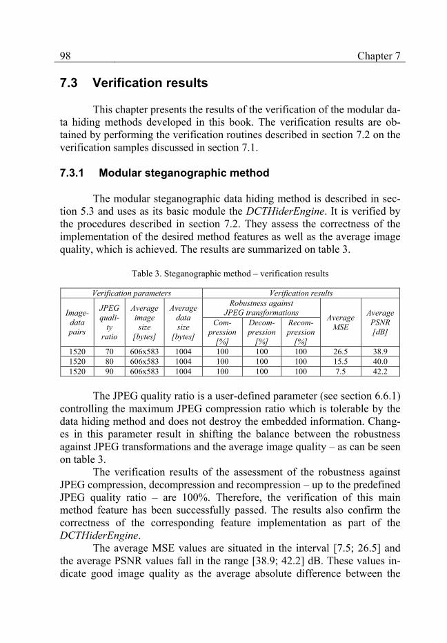
98 Chapter 7
7.3 Verification results
This chapter presents the results of the verification of the modular da-ta hiding methods developed in this book. The verification results are ob-tained by performing the verification routines described in section 7.2 on the verification samples discussed in section 7.1.
7.3.1 Modular steganographic method
The modular steganographic data hiding method is described in sec-tion 5.3 and uses as its basic module the DCTHiderEngine. It is verified by the procedures described in section 7.2. They assess the correctness of the implementation of the desired method features as well as the average image quality, which is achieved. The results are summarized on table 3.
Table 3. Steganographic method – verification results
Verification parameters Verification results
Image-data pairs
JPEG quali-
ty ratio
Average image size
[bytes]
Average data size
[bytes]
Robustness against JPEG transformations Average
MSE
Average PSNR [dB]
Com-pression
[%]
Decom-pression
[%]
Recom-pression
[%] 1520 70 606x583 1004 100 100 100 26.5 38.9 1520 80 606x583 1004 100 100 100 15.5 40.0 1520 90 606x583 1004 100 100 100 7.5 42.2
The JPEG quality ratio is a user-defined parameter (see section 6.6.1)
controlling the maximum JPEG compression ratio which is tolerable by the data hiding method and does not destroy the embedded information. Chang-es in this parameter result in shifting the balance between the robustness against JPEG transformations and the average image quality – as can be seen on table 3.
The verification results of the assessment of the robustness against JPEG compression, decompression and recompression – up to the predefined JPEG quality ratio – are 100%. Therefore, the verification of this main method feature has been successfully passed. The results also confirm the correctness of the corresponding feature implementation as part of the DCTHiderEngine.
The average MSE values are situated in the interval [7.5; 26.5] and the average PSNR values fall in the range [38.9; 42.2] dB. These values in-dicate good image quality as the average absolute difference between the

Verification and evaluation 99
original image and the image after data hiding is fairly small. The average data size of 1004 bytes is reasonable taking into consideration the average image dimensions of pixels and the robustness against JPEG transformations.
As to be expected, an increase of the predefined JPEG quality ratio, which diminishes the robustness against JPEG transformations, leads to an increase of the average image quality after data hiding. This is indicated by the falling MSE values. In spite of their significant decrease, the change in the corresponding average PSNR values is much smaller.
7.3.2 Modular digital watermarking method
The modular digital watermarking method is described in section 5.4 and uses as its basic module the DCTHiderEngine. In analogy to the modular steganographic method, it is verified by the procedures described in section 7.2. They assess the robustness against JPEG transformations and the aver-age image quality achieved by the data hiding method. The results are sum-marized on table 4:
Table 4. Digital watermarking method – verification results
Verification parameters Verification results
Image-data pairs
JPEG quali-
ty ratio
Average image size
[pixels]
Average data size
[bytes]
Robustness against JPEG transformations Average
MSE
Average PSNR [dB]
Com-pression
[%]
Decom-pression
[%]
Recom-pression
[%] 760 70 606x583 39 100 100 100 26.3 38.3 760 80 606x583 39 100 100 100 15.0 39.9 760 90 606x583 39 100 100 100 7.0 42.4
The verification of the robustness against JPEG transformations has
been passed successfully – with a result equal to 100%. This result confirms once more the correct implementation of the DCTHiderEngine (see also the verification results presented on table 3).
The average MSE values are situated in the interval [7.0; 26.3] and the average PSNR values fall in the range [38.3; 42.4] dB. They are almost the same as the corresponding values for the steganographic method. They indicate good image quality as the average difference between the images before and after data hiding is fairly small. In comparison to the verification of the steganographic method, different data samples are used. Their average data size is smaller (39 bytes) due to the additional features provided by the digital watermarking method. The image samples remain the same.
100 Chapter 7
In analogy to the steganographic method, the image quality increases when the predefined JPEG quality ratio is increased. In this way, the user can select the appropriate trade-off between the robustness against JPEG transformations and the image quality.
7.4 Statistical steganalysis tests
An important consideration when choosing a data hiding method for practical applications is its capability to hide the embedded data not only from human users but also from statistical methods for steganalysis which employ algorithms designed to assess images without constant human super-vision. As part of their research, data hiding experts have developed several general statistical algorithms capable of detecting data hiding in JPEG imag-es. For detailed information about steganalysis and the developed algorithms see [6], [9], [32], [56], [57], [60], [61], [106].
This section presents the assessment of the performance of such sta-tistical algorithms for data hiding detection on the modular data hiding methods. For this purpose, the open-source program Stegdetect [107] devel-oped by Niels Provos is used. Stegdetect can run up to four different statisti-cal tests which detect the presence of data embedded by some popular ste-ganographic programs such as JSteg, JPHide or OutGuess. The detection sensitivity of the statistical tests can be controlled via a special Stegdetect command-line parameter named Sensitivity.
In order to evaluate the performance of steganalysis algorithms with regard to the detection of data embedded by the modular data hiding meth-ods, Stegdetect is run on three sets of JPEG images. The first set consists of the original image test samples (converted in JPEG) which do not contain any embedded data.
The second and the third set are composed of images containing data embedded respectively by the steganographic data hiding method and by the digital watermarking method. The images are obtained as a result from the verification procedures described in section 7.2 under the default JPEG qual-ity ratio of 70. The data test samples which are embedded are different for each one of the two image sets. They are discussed in detail in section 7.1.1.
For each tested image of each set, Stegdetect gives an assumption whether it contains embedded data or not. The assumption is based on four different statistical steganalysis tests. After all images belonging to a given set have been examined by Stegdetect, the percentage Pno data of the images assumed to contain no hidden data can be calculated:
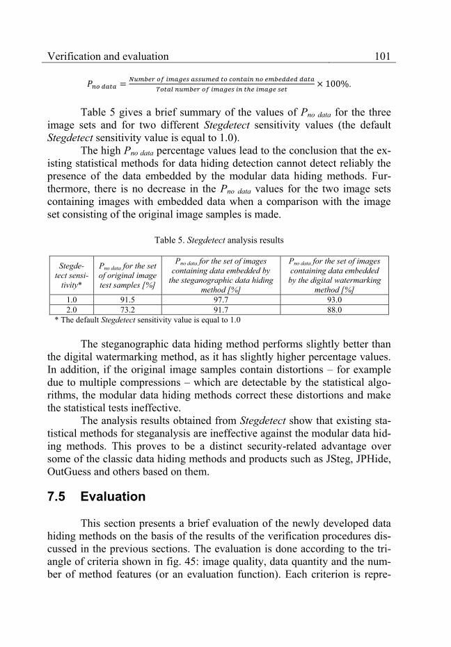
Verification and evaluation 101
.
Table 5 gives a brief summary of the values of Pno data for the three
image sets and for two different Stegdetect sensitivity values (the default Stegdetect sensitivity value is equal to 1.0).
The high Pno data percentage values lead to the conclusion that the ex-isting statistical methods for data hiding detection cannot detect reliably the presence of the data embedded by the modular data hiding methods. Fur-thermore, there is no decrease in the Pno data values for the two image sets containing images with embedded data when a comparison with the image set consisting of the original image samples is made.
Table 5. Stegdetect analysis results
Stegde-tect sensi-
tivity*
Pno data for the set of original image test samples [%]
Pno data for the set of images containing data embedded by
the steganographic data hiding method [%]
Pno data for the set of images containing data embedded
by the digital watermarking method [%]
1.0 91.5 97.7 93.0 2.0 73.2 91.7 88.0
* The default Stegdetect sensitivity value is equal to 1.0 The steganographic data hiding method performs slightly better than
the digital watermarking method, as it has slightly higher percentage values. In addition, if the original image samples contain distortions – for example due to multiple compressions – which are detectable by the statistical algo-rithms, the modular data hiding methods correct these distortions and make the statistical tests ineffective.
The analysis results obtained from Stegdetect show that existing sta-tistical methods for steganalysis are ineffective against the modular data hid-ing methods. This proves to be a distinct security-related advantage over some of the classic data hiding methods and products such as JSteg, JPHide, OutGuess and others based on them.
7.5 Evaluation
This section presents a brief evaluation of the newly developed data hiding methods on the basis of the results of the verification procedures dis-cussed in the previous sections. The evaluation is done according to the tri-angle of criteria shown in fig. 45: image quality, data quantity and the num-ber of method features (or an evaluation function). Each criterion is repre-
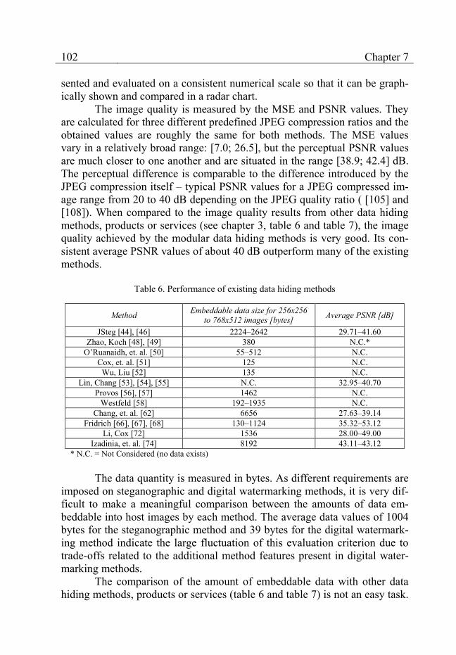
102 Chapter 7
sented and evaluated on a consistent numerical scale so that it can be graph-ically shown and compared in a radar chart.
The image quality is measured by the MSE and PSNR values. They are calculated for three different predefined JPEG compression ratios and the obtained values are roughly the same for both methods. The MSE values vary in a relatively broad range: [7.0; 26.5], but the perceptual PSNR values are much closer to one another and are situated in the range [38.9; 42.4] dB. The perceptual difference is comparable to the difference introduced by the JPEG compression itself – typical PSNR values for a JPEG compressed im-age range from 20 to 40 dB depending on the JPEG quality ratio ( [105] and [108]). When compared to the image quality results from other data hiding methods, products or services (see chapter 3, table 6 and table 7), the image quality achieved by the modular data hiding methods is very good. Its con-sistent average PSNR values of about 40 dB outperform many of the existing methods.
Table 6. Performance of existing data hiding methods
Method Embeddable data size for 256x256 to 768x512 images [bytes] Average PSNR [dB]
JSteg [44], [46] 2224–2642 29.71–41.60 Zhao, Koch [48], [49] 380 N.C.*
O’Ruanaidh, et. al. [50] 55–512 N.C. Cox, et. al. [51] 125 N.C.
Wu, Liu [52] 135 N.C. Lin, Chang [53], [54], [55] N.C. 32.95–40.70
Provos [56], [57] 1462 N.C. Westfeld [58] 192–1935 N.C.
Chang, et. al. [62] 6656 27.63–39.14 Fridrich [66], [67], [68] 130–1124 35.32–53.12
Li, Cox [72] 1536 28.00–49.00 Izadinia, et. al. [74] 8192 43.11–43.12
* N.C. = Not Considered (no data exists) The data quantity is measured in bytes. As different requirements are
imposed on steganographic and digital watermarking methods, it is very dif-ficult to make a meaningful comparison between the amounts of data em-beddable into host images by each method. The average data values of 1004 bytes for the steganographic method and 39 bytes for the digital watermark-ing method indicate the large fluctuation of this evaluation criterion due to trade-offs related to the additional method features present in digital water-marking methods.
The comparison of the amount of embeddable data with other data hiding methods, products or services (table 6 and table 7) is not an easy task.
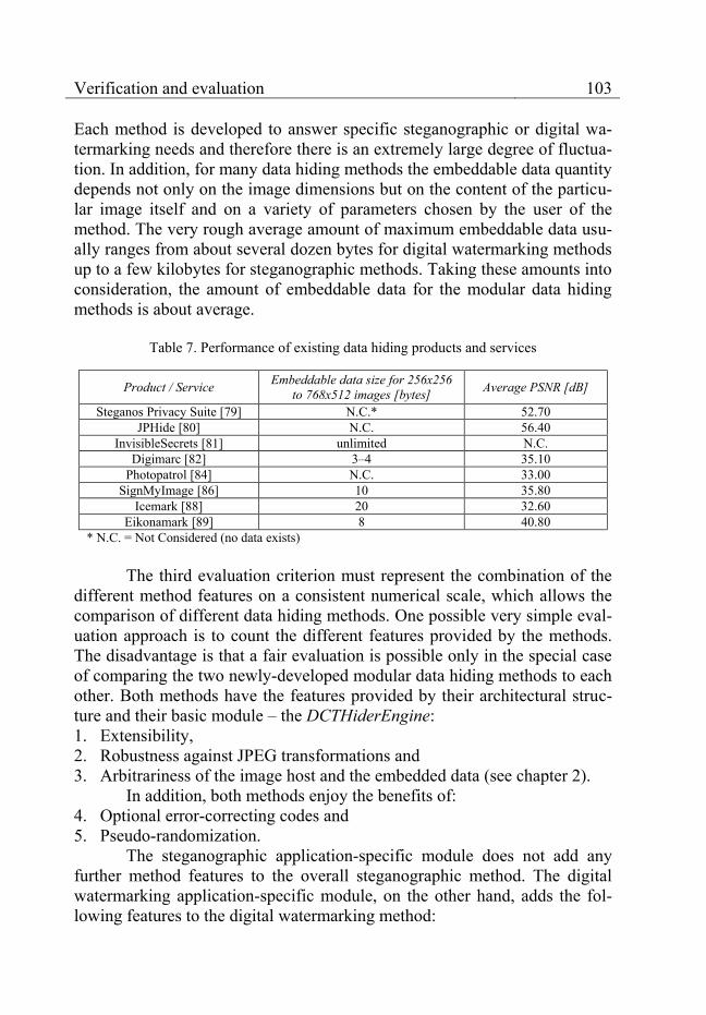
Verification and evaluation 103
Each method is developed to answer specific steganographic or digital wa-termarking needs and therefore there is an extremely large degree of fluctua-tion. In addition, for many data hiding methods the embeddable data quantity depends not only on the image dimensions but on the content of the particu-lar image itself and on a variety of parameters chosen by the user of the method. The very rough average amount of maximum embeddable data usu-ally ranges from about several dozen bytes for digital watermarking methods up to a few kilobytes for steganographic methods. Taking these amounts into consideration, the amount of embeddable data for the modular data hiding methods is about average.
Table 7. Performance of existing data hiding products and services
Product / Service Embeddable data size for 256x256 to 768x512 images [bytes] Average PSNR [dB]
Steganos Privacy Suite [79] N.C.* 52.70 JPHide [80] N.C. 56.40
InvisibleSecrets [81] unlimited N.C. Digimarc [82] 3–4 35.10
Photopatrol [84] N.C. 33.00 SignMyImage [86] 10 35.80
Icemark [88] 20 32.60 Eikonamark [89] 8 40.80
* N.C. = Not Considered (no data exists) The third evaluation criterion must represent the combination of the
different method features on a consistent numerical scale, which allows the comparison of different data hiding methods. One possible very simple eval-uation approach is to count the different features provided by the methods. The disadvantage is that a fair evaluation is possible only in the special case of comparing the two newly-developed modular data hiding methods to each other. Both methods have the features provided by their architectural struc-ture and their basic module – the DCTHiderEngine: 1. Extensibility, 2. Robustness against JPEG transformations and 3. Arbitrariness of the image host and the embedded data (see chapter 2).
In addition, both methods enjoy the benefits of: 4. Optional error-correcting codes and 5. Pseudo-randomization.
The steganographic application-specific module does not add any further method features to the overall steganographic method. The digital watermarking application-specific module, on the other hand, adds the fol-lowing features to the digital watermarking method:
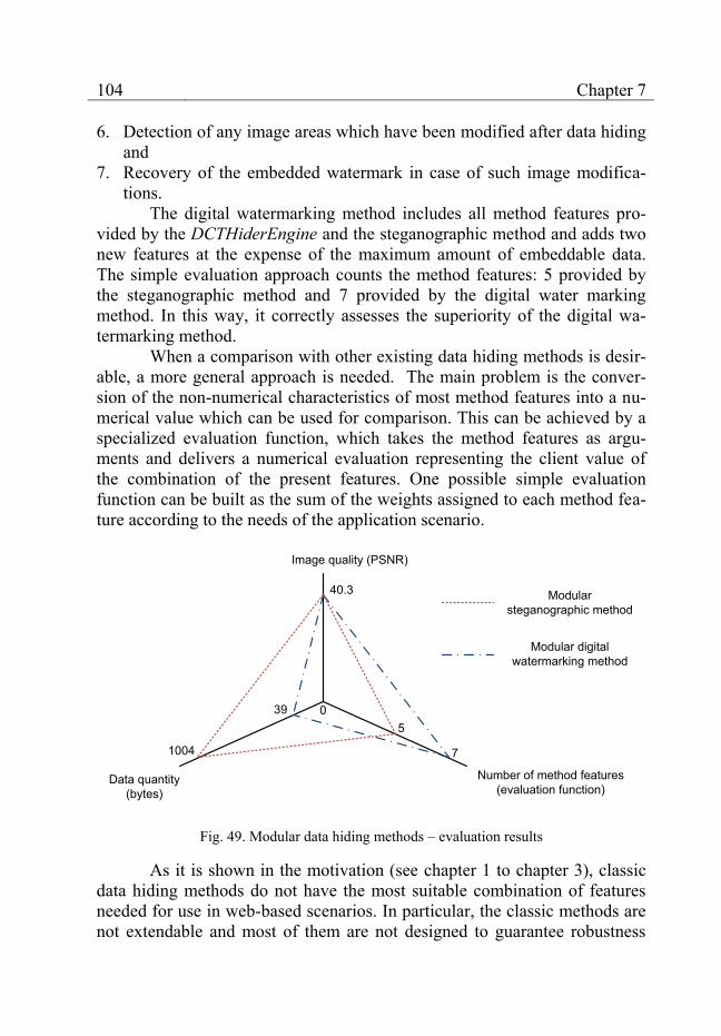
104 Chapter 7
6. Detection of any image areas which have been modified after data hiding and
7. Recovery of the embedded watermark in case of such image modifica-tions.
The digital watermarking method includes all method features pro-vided by the DCTHiderEngine and the steganographic method and adds two new features at the expense of the maximum amount of embeddable data. The simple evaluation approach counts the method features: 5 provided by the steganographic method and 7 provided by the digital water marking method. In this way, it correctly assesses the superiority of the digital wa-termarking method.
When a comparison with other existing data hiding methods is desir-able, a more general approach is needed. The main problem is the conver-sion of the non-numerical characteristics of most method features into a nu-merical value which can be used for comparison. This can be achieved by a specialized evaluation function, which takes the method features as argu-ments and delivers a numerical evaluation representing the client value of the combination of the present features. One possible simple evaluation function can be built as the sum of the weights assigned to each method fea-ture according to the needs of the application scenario.
Image quality (PSNR)
Data quantity (bytes)
Number of method features(evaluation function)
0
7
40.3
1004
539
Modular digital watermarking method
Modular steganographic method
Fig. 49. Modular data hiding methods – evaluation results
As it is shown in the motivation (see chapter 1 to chapter 3), classic data hiding methods do not have the most suitable combination of features needed for use in web-based scenarios. In particular, the classic methods are not extendable and most of them are not designed to guarantee robustness
Verification and evaluation 105
against all JPEG transformations. Therefore, their evaluation cannot achieve the same results as the evaluation of the modular data hiding methods. Of course, if the usage context changes, the user requirements towards the data hiding methods will change, as well. These changes will be reflected in the feature evaluation function possibly leading to different evaluation results.
A radar diagram summarizing the evaluation results is shown in fig. 49. The diagram uses the average PSNR value for both methods as image quality estimation. The data quantity is represented by the average data size. The evaluation function used on the method features axis is equal to the number of features provided by each method. The diagram emphasizes the trade-off between the amount of embeddable data and the two new features provided by the digital watermarking method. This trade-off shifts the area formed by the triangles which represent the overall evaluations of each method.
Furthermore, the shifts of the triangular areas correspond to changes in the practical applications of the methods. Via analysis of the user re-quirements, minimum values for each evaluation criterion may be specified – minimum average PSNR value, minimum embeddable data size and meth-od features required in the corresponding web-based application scenario. In this way, a minimum triangular area for each particular scenario can be spec-ified and every data hiding method which claims to satisfy the user require-ments must cover this area.
If necessary, the radar diagram can be extended to include other method characteristics such as the execution speed or the memory require-ments of the method. Thus, it enables a flexible and concise description of data hiding methods and allows a swift evaluation of their applicability in concrete web-based scenarios.
7.6 Conclusion
The verification discussed in this chapter provides empirical proof with regard to the quality of the new modular data hiding methods. The methods successfully implement the web-related features discussed in chap-ter 2 and meet the goals discussed in chapter 4. They are not detectable by classic statistical algorithms for data hiding detection.
Compared to existing data hiding methods, the modular data hiding methods provide very good image quality and can embed an average amount of data. Their main advantage consists in the unique combination of method features, which other data hiding methods do not provide. The extensibility
106 Chapter 7
feature is new and it is especially important because it enables the easy mod-ification of the methods for use in different application areas.
By means of the easily extendable multi-criteria evaluation scheme, the methods can be categorized according to their performance. For every web-based scenario, the user requirements can be specified in terms of the evaluation scheme and then the modular method offering the most suitable combination of image quality, amount of embedded data and method fea-tures can be selected, implemented and put into operation. If need be, a new method providing the necessary balance between the evaluation criteria can be created by modifying the existing application-specific modules or using a different combination of basic and application-specific modules. Then, the new method can be evaluated with regard to the achievement of better con-formance to the user requirements and, if successful, it will be stored for fu-ture use in similar application scenarios.

107
Chapter 8 Application in web-based scenarios
In this chapter, the practical application of the new modular data hid-ing methods in three concrete web-based scenarios is discussed – phishing prevention for bank portals, multimedia protection for news agencies and improving the legal use of multimedia content in web-based societies. The additional benefits of the data hiding methods for the companies involved in these scenarios and their clients are described and a proof-of-concept client-server implementation geared to the needs of the scenarios is presented. The concept and the implementation of a data hiding certification service are dis-cussed in detail and its usage in both scenarios is illustrated.
8.1 Phishing prevention for bank portals
This scenario discusses how the security of bank portals can be im-proved by the addition of data hiding methods to the traditional security technologies which banks already use. The scenario is also relevant for other corporations which have online portals providing direct customer access to the corporate infrastructure – mobile operators such as Vodafone or O2, large online shops such as Amazon or eBay and online payment services such as PayPal.
8.1.1 Phishing overview
Phishing is an approach used by criminals to acquire sensitive client data such as personal identification numbers (PINs), transaction authentica-tion numbers (TANs), bank account numbers, credit card numbers and pass-words.
In the usual case, the victim receives a fraudulent e-mail that appears to come from a respected bank (or another institution) which the victim has an account with. In the e-mail the victim is told that his or her account has been closed or that a large transaction has been made in his/her name. The message aims at scaring the victim that something is wrong and that imme-
108 Chapter 8
diate action is required to prevent serious monetary loss. Then, clear direc-tions to remedy the problem are provided.
The victim must first click on a well-visible hyperlink in the e-mail which pretends to open the bank’s web portal. The hyperlink actually opens an imitation of the real web portal which is under the control of the sender of the e-mail. The victim is then asked to enter some sensitive data on the fake web portal (a PIN, a TAN, a bank account number or a credit card number) in order to solve the imaginary problem. As soon as the victim enters the re-quested data, it can be used by the sender of the phishing e-mail for illegal purposes.
Another variation of phishing takes advantage of the Domain Name System (DNS) resolution process. Before accessing a web portal, the client browser has to substitute the host name typed by the user (such as www.example.com) for an IP address (such as 208.77.188.166), which is the actual unique identifier of every Internet server in the global network.
If a hacker can influence the DNS resolution process, he or she can change the IP address which corresponds to the host name of the bank web portal. In this way, even though the victim has correctly entered the host name of the web portal, the browser will be directed to the fake bank portal of the hacker.
Phishing is a dangerous phenomenon because, if the victim is not careful, he or she does not become aware of the phishing attempt at all. By the time the collected sensitive data is used for illegal purposes, it is too late to remedy the problem.
8.1.2 Disadvantages of traditional security technologies
Current security schemes for web portals rely on web certificates (fig. 50), which are based on the public-key cryptographic approach and the Rivest-Shamir-Adleman (RSA) encryption algorithm [15]. The web certifi-cates may be self-signed or issued by a global certification authority (CA), which verifies the identity of the owner of the web portal.
Web certificates serve two major goals. The first goal is to provide an end-to-end encryption, so that no eavesdropping on the transmitted data is possible. The second goal, which is relevant to phishing, is to provide a mechanism for the verification of the identity of the web portal’s owner. The verification relies on the trust placed by the users in the corresponding certi-fication authority. The CA guarantees that the web portal is operated by the company indicated in the web certificate.
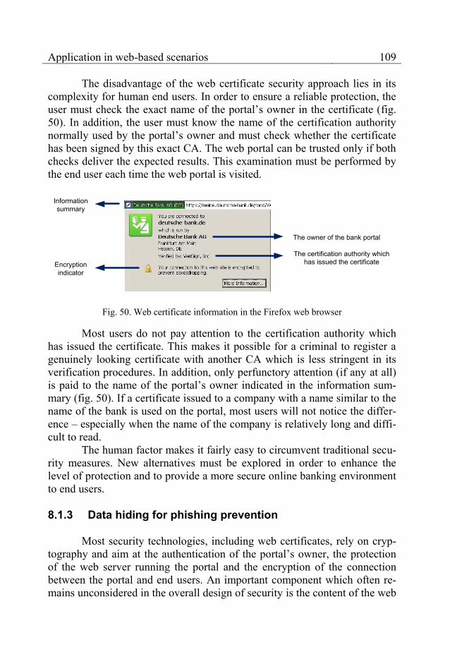
Application in web-based scenarios 109
The disadvantage of the web certificate security approach lies in its complexity for human end users. In order to ensure a reliable protection, the user must check the exact name of the portal’s owner in the certificate (fig. 50). In addition, the user must know the name of the certification authority normally used by the portal’s owner and must check whether the certificate has been signed by this exact CA. The web portal can be trusted only if both checks deliver the expected results. This examination must be performed by the end user each time the web portal is visited.
The owner of the bank portal
The certification authority which has issued the certificate
Information summary
Encryption indicator
Fig. 50. Web certificate information in the Firefox web browser
Most users do not pay attention to the certification authority which has issued the certificate. This makes it possible for a criminal to register a genuinely looking certificate with another CA which is less stringent in its verification procedures. In addition, only perfunctory attention (if any at all) is paid to the name of the portal’s owner indicated in the information sum-mary (fig. 50). If a certificate issued to a company with a name similar to the name of the bank is used on the portal, most users will not notice the differ-ence – especially when the name of the company is relatively long and diffi-cult to read.
The human factor makes it fairly easy to circumvent traditional secu-rity measures. New alternatives must be explored in order to enhance the level of protection and to provide a more secure online banking environment to end users.
8.1.3 Data hiding for phishing prevention
Most security technologies, including web certificates, rely on cryp-tography and aim at the authentication of the portal’s owner, the protection of the web server running the portal and the encryption of the connection between the portal and end users. An important component which often re-mains unconsidered in the overall design of security is the content of the web
110 Chapter 8
portal itself. Traditional security schemes regard the content as a passive ob-ject, which they protect or regulate the access to. The only function of the content on the web portal is to satisfy the needs of the end users.
Data hiding technologies can enable the active usage of the portal’s content for the enhancement of the overall security. They can add an addi-tional function to the content – to assist in the authentication of the web por-tal and thus to facilitate the prevention of phishing.
The content of most modern portals consists of a mixture of multi-media: text, images, video, etc. Data hiding methods can embed data into this content, which may contain or point to detailed copyright information, information related to the legitimate web portal, a traditional web certificate or a combination of the three. In this way the multimedia content can be au-thenticated and linked to its legitimate location. Furthermore, the application of data hiding to all incoming multimedia items can be easily automated.
If phishing is attempted, the original multimedia content from the bank portal must be either uploaded directly to the fake portal or it must be imitated. In the first case the authentication information contained in the multimedia will not match the fake portal. In the second case there will be no authentication information. Both cases are easy to detect by a client that ex-pects to find the proper authentication information on the web portal.
On the client side, the examination of the multimedia items on the bank portal is ideally performed automatically by an extension of a tradition-al web browser such as Firefox. It extracts and compares the multimedia sig-natures with the web portal they reside on. If a mismatch is detected, the user is notified of the potential phishing attempt.
Data hiding allows each multimedia item to have its own small signa-ture which can be compared to the web portal it resides on. As the signatures are an integral part of the multimedia, this security enhancement is not as obvious as most cryptographic approaches and it is difficult to detect and remove by potential attackers. Furthermore, it is fully backward compatible with any clients that are not able or willing to process the additional signa-tures.
8.1.4 Data hiding as a certification service
The modular data hiding methods discussed in this book handle the authentication of JPEG images and, with some enhancement, the authentica-tion of MPEG video streams. Their practical application in almost any web-based scenario can be facilitated by the creation of suitable web-service in-terfaces as presented in section 6.6.4.
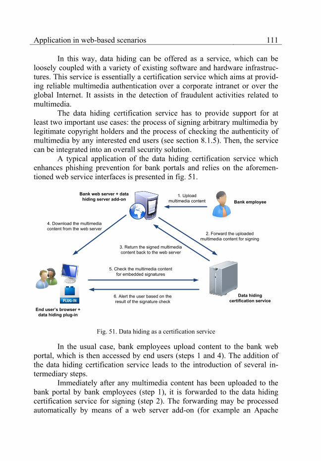
Application in web-based scenarios 111
In this way, data hiding can be offered as a service, which can be loosely coupled with a variety of existing software and hardware infrastruc-tures. This service is essentially a certification service which aims at provid-ing reliable multimedia authentication over a corporate intranet or over the global Internet. It assists in the detection of fraudulent activities related to multimedia.
The data hiding certification service has to provide support for at least two important use cases: the process of signing arbitrary multimedia by legitimate copyright holders and the process of checking the authenticity of multimedia by any interested end users (see section 8.1.5). Then, the service can be integrated into an overall security solution.
A typical application of the data hiding certification service which enhances phishing prevention for bank portals and relies on the aforemen-tioned web service interfaces is presented in fig. 51.
Data hiding certification service
Bank web server + data hiding server add-on Bank employee
End user’s browser + data hiding plug-in
5. Check the multimedia content for embedded signatures
6. Alert the user based on the result of the signature check
1. Upload multimedia content
2. Forward the uploaded multimedia content for signing
3. Return the signed multimedia content back to the web server
4. Download the multimedia content from the web server
Fig. 51. Data hiding as a certification service
In the usual case, bank employees upload content to the bank web portal, which is then accessed by end users (steps 1 and 4). The addition of the data hiding certification service leads to the introduction of several in-termediary steps.
Immediately after any multimedia content has been uploaded to the bank portal by bank employees (step 1), it is forwarded to the data hiding certification service for signing (step 2). The forwarding may be processed automatically by means of a web server add-on (for example an Apache
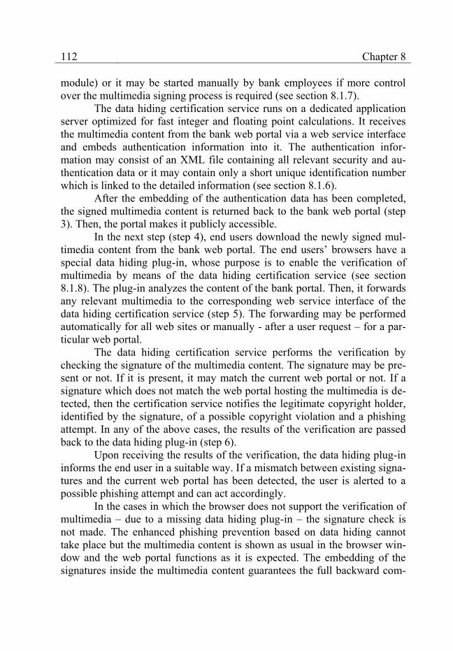
112 Chapter 8
module) or it may be started manually by bank employees if more control over the multimedia signing process is required (see section 8.1.7).
The data hiding certification service runs on a dedicated application server optimized for fast integer and floating point calculations. It receives the multimedia content from the bank web portal via a web service interface and embeds authentication information into it. The authentication infor-mation may consist of an XML file containing all relevant security and au-thentication data or it may contain only a short unique identification number which is linked to the detailed information (see section 8.1.6).
After the embedding of the authentication data has been completed, the signed multimedia content is returned back to the bank web portal (step 3). Then, the portal makes it publicly accessible.
In the next step (step 4), end users download the newly signed mul-timedia content from the bank web portal. The end users’ browsers have a special data hiding plug-in, whose purpose is to enable the verification of multimedia by means of the data hiding certification service (see section 8.1.8). The plug-in analyzes the content of the bank portal. Then, it forwards any relevant multimedia to the corresponding web service interface of the data hiding certification service (step 5). The forwarding may be performed automatically for all web sites or manually - after a user request – for a par-ticular web portal.
The data hiding certification service performs the verification by checking the signature of the multimedia content. The signature may be pre-sent or not. If it is present, it may match the current web portal or not. If a signature which does not match the web portal hosting the multimedia is de-tected, then the certification service notifies the legitimate copyright holder, identified by the signature, of a possible copyright violation and a phishing attempt. In any of the above cases, the results of the verification are passed back to the data hiding plug-in (step 6).
Upon receiving the results of the verification, the data hiding plug-in informs the end user in a suitable way. If a mismatch between existing signa-tures and the current web portal has been detected, the user is alerted to a possible phishing attempt and can act accordingly.
In the cases in which the browser does not support the verification of multimedia – due to a missing data hiding plug-in – the signature check is not made. The enhanced phishing prevention based on data hiding cannot take place but the multimedia content is shown as usual in the browser win-dow and the web portal functions as it is expected. The embedding of the signatures inside the multimedia content guarantees the full backward com-

Application in web-based scenarios 113
patibility of the security solutions based on the data hiding certification ser-vice.
The prototype implementation of the data hiding certification service in this book uses the Microsoft Internet Information Server (IIS) installed on a separate dedicated server. The dedicated server provides the computing power necessary for the execution of the modular data hiding methods. The IIS handles the requests to the web service interfaces used for the interaction with the data hiding certification service. It makes the functionality of the service accessible to other components involved in the phishing prevention scenario such as the server add-on of the bank web portal or the data hiding plug-ins in end users’ browsers.
In the following sections, the web service interface of data hiding certification service and the authentication information that is embedded into the multimedia content are discussed in detail. In addition, the integration of the service with the bank web portal and end users’ browsers is illustrated.
8.1.5 Web service interface
In close analogy to the web service interface described in section 6.6.4, a new web service interface is created, which is specially geared to-wards multimedia authentication.
The data hiding certification service must handle the signing of mul-timedia content and the verification of existing signatures. The signing of multimedia is processed by the hideCopyrightInformationByImage web ser-vice operation. A typical SOAP request and response are presented respec-tively in fig. 52 and fig. 53.
The SOAP request shown in fig. 52 passes the following parameters to the web service: 1. sourceImage: the host image which is to be signed (encoded in the
base64 format); 2. destinationImageFormat: the image format of the signed image after data
hiding (currently either JPG or BMP); 3. errorCorrection: a Boolean value controlling the optional usage of error-
correction: true if the error-correction is enabled and false if the error-correction is disabled;
4. withstandJPEGCompressionRatio: the maximum JPEG compression ra-tio which can be applied to the signed image – the image containing the authentication information – without destroying the embedded data;
5. copyrightHolder: the name of the legitimate copyright holder of the signed multimedia content;
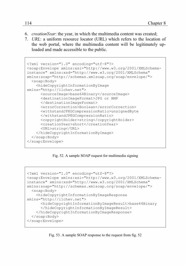
114 Chapter 8
6. creationYear: the year, in which the multimedia content was created; 7. URL: a uniform resource locator (URL) which refers to the location of
the web portal, where the multimedia content will be legitimately up-loaded and made accessible to the public.
<?xml version="1.0" encoding="utf-8"?>
<soap:Envelope xmlns:xsi="http://www.w3.org/2001/XMLSchema-
instance" xmlns:xsd="http://www.w3.org/2001/XMLSchema"
xmlns:soap="http://schemas.xmlsoap.org/soap/envelope/">
<soap:Body>
<hideCopyrightInformationByImage
xmlns="http://ilchev.net">
<sourceImage>base64Binary</sourceImage>
<destinationImageFormat>JPG or BMP
</destinationImageFormat>
<errorCorrection>Boolean</errorCorrection>
<withstandJPEGCompressionRatio>unsignedByte
</withstandJPEGCompressionRatio>
<copyrightHolder>string</copyrightHolder>
<creationYear>short</creationYear>
<URL>string</URL>
</hideCopyrightInformationByImage>
</soap:Body>
</soap:Envelope>
Fig. 52. A sample SOAP request for multimedia signing
<?xml version="1.0" encoding="utf-8"?>
<soap:Envelope xmlns:xsi="http://www.w3.org/2001/XMLSchema-
instance" xmlns:xsd="http://www.w3.org/2001/XMLSchema"
xmlns:soap="http://schemas.xmlsoap.org/soap/envelope/">
<soap:Body>
<hideCopyrightInformationByImageResponse
xmlns="http://ilchev.net">
<hideCopyrightInformationByImageResult>base64Binary
</hideCopyrightInformationByImageResult>
</hideCopyrightInformationByImageResponse>
</soap:Body>
</soap:Envelope>
Fig. 53. A sample SOAP response to the request from fig. 52

Application in web-based scenarios 115
<?xml version="1.0" encoding="utf-8"?>
<soap:Envelope
xmlns:xsi="http://www.w3.org/2001/XMLSchema-instance"
xmlns:xsd="http://www.w3.org/2001/XMLSchema"
xmlns:soap="http://schemas.xmlsoap.org/soap/envelope/">
<soap:Body>
<unHideCopyrightInformationByURL
xmlns="http://ilchev.net">
<imageURL>string</imageURL>
</unHideCopyrightInformationByURL>
</soap:Body>
</soap:Envelope>
Fig. 54. A sample SOAP request for signature verification
The parameters presented above are divided into two broad catego-ries – parameters related to the operation of the data hiding methods (param-eters 1 to 4) and parameters related to the authentication of the multimedia content (parameters 5 to 7). The latter group can be easily supplemented by other relevant information such as the name or the IP address of the web por-tal or a web certificate (see also section 8.1.6).
<?xml version="1.0" encoding="utf-8"?>
<soap:Envelope
xmlns:xsi="http://www.w3.org/2001/XMLSchema-instance"
xmlns:xsd="http://www.w3.org/2001/XMLSchema"
xmlns:soap="http://schemas.xmlsoap.org/soap/envelope/">
<soap:Body>
<unHideCopyrightInformationByURLResponse
xmlns="http://ilchev.net">
<unHideCopyrightInformationByURLResult>xml
</unHideCopyrightInformationByURLResult>
</unHideCopyrightInformationByURLResponse>
</soap:Body>
</soap:Envelope>
Fig. 55. A sample SOAP response to the request from fig. 54
The response returned by the web service method is shown in fig. 53. It contains the signed multimedia encoded in base64 format.
116 Chapter 8
The verification of the embedded signatures is handled by the un-HideCopyrightInformationByURL web service operation. A typical SOAP request and response are presented respectively in fig. 54 and fig. 55.
The only parameter passed to the web service is imageURL – the URL of the image whose signature is to be verified. The SOAP response re-turns an XML document containing the authentication information extracted from the image. It may have the exact structure described in section 8.1.6 or it may be extended to incorporate some other relevant information such as the time and duration of the verification.
The next section describes the structure and the content of the au-thentication information, which is assembled by the data hiding certification service on the basis of the input parameters and then embedded into the mul-timedia content.
8.1.6 Authentication information
This section discusses the authentication information embedded by the data hiding certification service. There are two basic approaches which may be implemented and which achieve a different trade-off between the size of the embedded information and the ease and flexibility of the imple-mentation.
The first approach embeds the whole information into the multimedia content in the form of an XML file. The XML file is relatively large (typical-ly a few hundred bytes) but it has the advantage of securely encoding all au-thentication data inside the multimedia stream. In this way, when the signa-ture of the multimedia content is verified, no additional inputs are necessary. The multimedia content itself is sufficient to perform the verification.
This approach is easy to use and offers good flexibility as the struc-ture of the XML file can be modified quickly to answer changes in user re-quirements. The main disadvantage is the large size of the embedded infor-mation.
The structure of the XML-based authentication information is de-fined by the XSD schema shown in fig. 56. The root element is named Im-ageInformation. It may contain child elements describing the legitimate cop-yright holder (element Copyright) and the web portal where the multimedia is situated (element Location). Optionally, a web certificate pertaining to the multimedia content may be saved in a base64 format (element Certificate). The Copyright element may contain several child elements. The first child element specifies the year of creation of the multimedia content (element
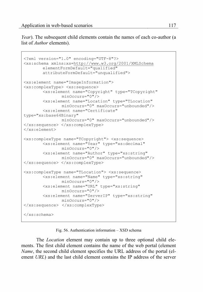
Application in web-based scenarios 117
Year). The subsequent child elements contain the names of each co-author (a list of Author elements).
<?xml version="1.0" encoding="UTF-8"?>
<xs:schema xmlns:xs=http://www.w3.org/2001/XMLSchema
elementFormDefault="qualified"
attributeFormDefault="unqualified">
<xs:element name="ImageInformation">
<xs:complexType> <xs:sequence>
<xs:element name="Copyright" type="TCopyright"
minOccurs="0"/>
<xs:element name="Location" type="TLocation"
minOccurs="0" maxOccurs="unbounded"/>
<xs:element name="Certificate"
type="xs:base64Binary"
minOccurs="0" maxOccurs="unbounded"/>
</xs:sequence> </xs:complexType>
</xs:element>
<xs:complexType name="TCopyright"> <xs:sequence>
<xs:element name="Year" type="xs:decimal"
minOccurs="0"/>
<xs:element name="Author" type="xs:string"
minOccurs="0" maxOccurs="unbounded"/>
</xs:sequence> </xs:complexType>
<xs:complexType name="TLocation"> <xs:sequence>
<xs:element name="Name" type="xs:string"
minOccurs="0"/>
<xs:element name="URL" type="xs:string"
minOccurs="0"/>
<xs:element name="ServerIP" type="xs:string"
minOccurs="0"/>
</xs:sequence> </xs:complexType>
</xs:schema>
Fig. 56. Authentication information – XSD schema
The Location element may contain up to three optional child ele-ments. The first child element contains the name of the web portal (element Name, the second child element specifies the URL address of the portal (el-ement URL) and the last child element contains the IP address of the server

118 Chapter 8
which hosts the web portal (element ServerIP). An exemplary XML docu-ment conforming to the XSD schema presented above is shown in fig. 57.
<?xml version="1.0" encoding="UTF-8"?>
<ImageInformation
xmlns:xsi="http://www.w3.org/2001/XMLSchema-instance"
xmlns:xsd="http://www.w3.org/2001/XMLSchema">
<Copyright>
<Year>2007</Year>
<Author>Svetozar Ilchev</Author>
</Copyright>
<Location>
<URL>ilchev.net/StegiWeb/DSC00014.JPG</URL>
</Location>
</ImageInformation>
Fig. 57. Authentication information – a sample XML document
The document contains information about the author, the year of cre-ation and the original location of a JPEG image published on the Internet. When it is embedded into the JPEG image, it will enable the verification of the image author and the legitimate location of the image without any need of further references.
An alternative to the embedding of a whole XML document into the multimedia content is the embedding of a unique multimedia identification number. This number is different for each signed multimedia item and pro-vides convenient means for the identification of the individual multimedia copies.
The verification of multimedia content signed with an identification number requires an external database which contains the actual authentica-tion information such as the names of the authors, the creation year or the locations of the web portals that may offer the multimedia content to the public. This information is stored in the database using the multimedia iden-tification number as a key.
During the verification process, the data hiding certification service extracts the multimedia identification number embedded into the multimedia content, accesses the external database and retrieves the authentication in-formation referenced by the multimedia authentication number. Then, the authentication information is formatted properly and analyzed. The results are returned back to the end user.
Application in web-based scenarios 119
The main advantage of this approach lies in the comparatively short length of the multimedia authentication number (typically about a hundred bits). The main disadvantage is related to the usage of an external database, which is connected with significant overhead. The database is an additional entity different from the multimedia content. It forms a single point of failure in comparison to the XML document approach, which relies solely on the distributed multimedia content.
First and foremost, the database has to be secured in a reliable way. If it is compromised, reliable multimedia authentication is no longer possible. Protection against accidental loss of the authentication information must be guaranteed, as well. Furthermore, the database is needed during the verifica-tion of each multimedia item passed to the certification service. If it cannot be accessed, the verification process cannot be completed.
This second approach offers a different trade-off between the size of the embedded information and the flexibility of the solution. Both approach-es offer viable alternatives for the handling of the authentication information and they both may be implemented and applied to the phishing prevention scenario. The current prototype implementation developed in this book relies on the XML document approach due to its superior flexibility.
The next two sections describe the integration of the data hiding cer-tification service with the existing infrastructure – the bank web portal and the web browsers of end users.
8.1.7 Integration with the bank web portal
The integration of the data hiding certification service with the bank web portal can be easily implemented using the web service interfaces de-scribed in section 8.1.5. For this purpose, the web server needs to forward any newly-uploaded unsigned multimedia file to the web service before it is made publicly accessible.
The forwarding may take place automatically by means of a web server add-on such as an Apache module, which supervises all multimedia content residing on the portal. When a new image or video file is uploaded, the access to it is initially forbidden. Then, the add-on passes the newly-uploaded file to the hideCopyrightInformationByImage web service opera-tion of the data hiding certification service. It signs the multimedia content and returns the resulting file back to the add-on. The add-on replaces the original file with the signed one and allows public access to it.
Another alternative is to keep a shell script running in the back-ground as a daemon, which continuously probes predefined file system di-

120 Chapter 8
rectories for new files. If new image or video files are detected, they are passed to the data hiding certification service for signing. When the service completes the signing process and returns the signed multimedia files, the shell script copies them to a publicly accessible file system directory.
Fig. 58. Manual multimedia signing – GUI
A third viable option is to let a human user decide which files are to be signed and which are not. A suitable Graphical User Interface (GUI) providing access to the uploaded multimedia files is required. The user must be able to specify some signature parameters such as the names of the copy-right holder, the creation year, or the legitimate location of the multimedia file on the web portal.
A prototype GUI enabling the manual control over multimedia sign-ing is shown in fig. 58. It has just completed successfully the signing of 4 image files situated in the directory specified by the Image directory text field. The files are in the JPEG image format as indicated by the Image for-mat combo box. The remaining three text fields specify the names of the copyright holder (text field Copyright holder), the year of creation of the im-
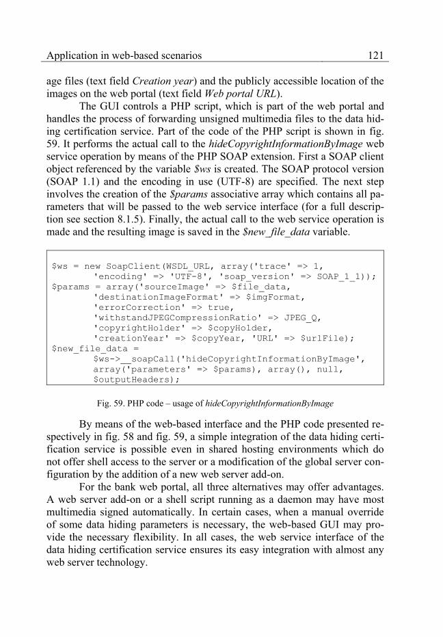
Application in web-based scenarios 121
age files (text field Creation year) and the publicly accessible location of the images on the web portal (text field Web portal URL).
The GUI controls a PHP script, which is part of the web portal and handles the process of forwarding unsigned multimedia files to the data hid-ing certification service. Part of the code of the PHP script is shown in fig. 59. It performs the actual call to the hideCopyrightInformationByImage web service operation by means of the PHP SOAP extension. First a SOAP client object referenced by the variable $ws is created. The SOAP protocol version (SOAP 1.1) and the encoding in use (UTF-8) are specified. The next step involves the creation of the $params associative array which contains all pa-rameters that will be passed to the web service interface (for a full descrip-tion see section 8.1.5). Finally, the actual call to the web service operation is made and the resulting image is saved in the $new_file_data variable.
$ws = new SoapClient(WSDL_URL, array('trace' => 1,
'encoding' => 'UTF-8', 'soap_version' => SOAP_1_1));
$params = array('sourceImage' => $file_data,
'destinationImageFormat' => $imgFormat,
'errorCorrection' => true,
'withstandJPEGCompressionRatio' => JPEG_Q,
'copyrightHolder' => $copyHolder,
'creationYear' => $copyYear, 'URL' => $urlFile);
$new_file_data =
$ws->__soapCall('hideCopyrightInformationByImage',
array('parameters' => $params), array(), null,
$outputHeaders);
Fig. 59. PHP code – usage of hideCopyrightInformationByImage
By means of the web-based interface and the PHP code presented re-spectively in fig. 58 and fig. 59, a simple integration of the data hiding certi-fication service is possible even in shared hosting environments which do not offer shell access to the server or a modification of the global server con-figuration by the addition of a new web server add-on.
For the bank web portal, all three alternatives may offer advantages. A web server add-on or a shell script running as a daemon may have most multimedia signed automatically. In certain cases, when a manual override of some data hiding parameters is necessary, the web-based GUI may pro-vide the necessary flexibility. In all cases, the web service interface of the data hiding certification service ensures its easy integration with almost any web server technology.

122 Chapter 8
8.1.8 Integration with end users’ browsers
The integration of the data hiding certification server with end users’ browsers relies to a large degree on the extensibility of the different browsers which exist on the market. Most modern browsers support browser exten-sions and user scripts for the purpose of extending the browser functionality.
Fig. 60. User script GUI before the data hiding verification
Browser extensions (also called add-ons or plug-ins) work as part of the browser itself. They can modify the browser behavior and appearance. They have also access to most of its internal libraries through a specially de-
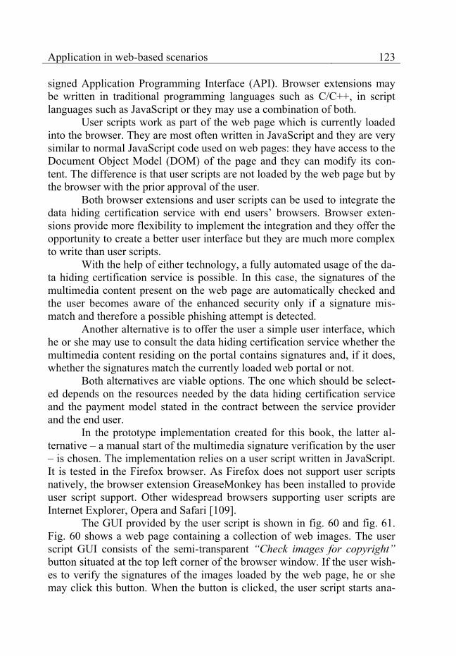
Application in web-based scenarios 123
signed Application Programming Interface (API). Browser extensions may be written in traditional programming languages such as C/C++, in script languages such as JavaScript or they may use a combination of both.
User scripts work as part of the web page which is currently loaded into the browser. They are most often written in JavaScript and they are very similar to normal JavaScript code used on web pages: they have access to the Document Object Model (DOM) of the page and they can modify its con-tent. The difference is that user scripts are not loaded by the web page but by the browser with the prior approval of the user.
Both browser extensions and user scripts can be used to integrate the data hiding certification service with end users’ browsers. Browser exten-sions provide more flexibility to implement the integration and they offer the opportunity to create a better user interface but they are much more complex to write than user scripts.
With the help of either technology, a fully automated usage of the da-ta hiding certification service is possible. In this case, the signatures of the multimedia content present on the web page are automatically checked and the user becomes aware of the enhanced security only if a signature mis-match and therefore a possible phishing attempt is detected.
Another alternative is to offer the user a simple user interface, which he or she may use to consult the data hiding certification service whether the multimedia content residing on the portal contains signatures and, if it does, whether the signatures match the currently loaded web portal or not.
Both alternatives are viable options. The one which should be select-ed depends on the resources needed by the data hiding certification service and the payment model stated in the contract between the service provider and the end user.
In the prototype implementation created for this book, the latter al-ternative – a manual start of the multimedia signature verification by the user – is chosen. The implementation relies on a user script written in JavaScript. It is tested in the Firefox browser. As Firefox does not support user scripts natively, the browser extension GreaseMonkey has been installed to provide user script support. Other widespread browsers supporting user scripts are Internet Explorer, Opera and Safari [109].
The GUI provided by the user script is shown in fig. 60 and fig. 61. Fig. 60 shows a web page containing a collection of web images. The user script GUI consists of the semi-transparent “Check images for copyright” button situated at the top left corner of the browser window. If the user wish-es to verify the signatures of the images loaded by the web page, he or she may click this button. When the button is clicked, the user script starts ana-
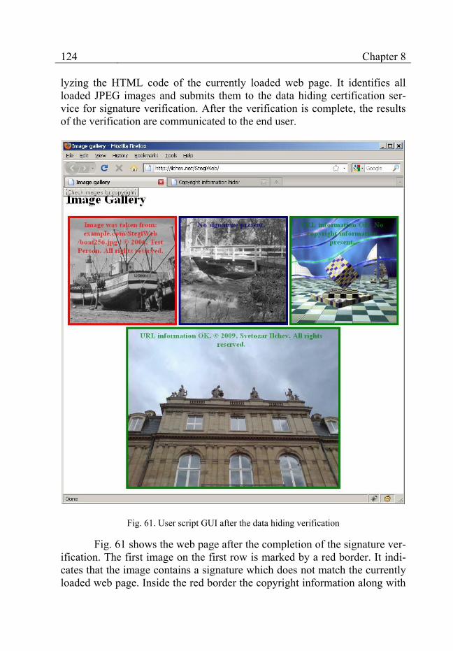
124 Chapter 8
lyzing the HTML code of the currently loaded web page. It identifies all loaded JPEG images and submits them to the data hiding certification ser-vice for signature verification. After the verification is complete, the results of the verification are communicated to the end user.
Fig. 61. User script GUI after the data hiding verification
Fig. 61 shows the web page after the completion of the signature ver-ification. The first image on the first row is marked by a red border. It indi-cates that the image contains a signature which does not match the currently loaded web page. Inside the red border the copyright information along with
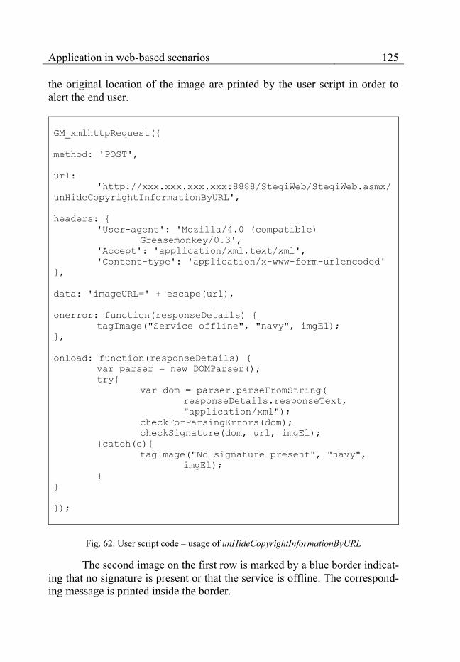
Application in web-based scenarios 125
the original location of the image are printed by the user script in order to alert the end user.
GM_xmlhttpRequest({
method: 'POST',
url:
'http://xxx.xxx.xxx.xxx:8888/StegiWeb/StegiWeb.asmx/
unHideCopyrightInformationByURL',
headers: {
'User-agent': 'Mozilla/4.0 (compatible)
Greasemonkey/0.3',
'Accept': 'application/xml,text/xml',
'Content-type': 'application/x-www-form-urlencoded'
},
data: 'imageURL=' + escape(url),
onerror: function(responseDetails) {
tagImage("Service offline", "navy", imgEl);
},
onload: function(responseDetails) {
var parser = new DOMParser();
try{
var dom = parser.parseFromString(
responseDetails.responseText,
"application/xml");
checkForParsingErrors(dom);
checkSignature(dom, url, imgEl);
}catch(e){
tagImage("No signature present", "navy",
imgEl);
}
}
});
Fig. 62. User script code – usage of unHideCopyrightInformationByURL
The second image on the first row is marked by a blue border indicat-ing that no signature is present or that the service is offline. The correspond-ing message is printed inside the border.

126 Chapter 8
The third image on the first row is marked by a green border indicat-ing the presence of a signature that matches the loaded web page. The signa-ture contains only the legitimate location of the image (coinciding with the current web page) but, according to the messages printed inside the green border, it does not contain any copyright information. This partial signature takes advantage of the flexibility provided by the XML format of the authen-tication information which is described in section 8.1.6.
The single image on the second row is also marked by a green bor-der. It contains a signature which matches the loaded web page. Further-more, the signature contains copyright information, which is printed by the user script in the green box surrounding the image.
During the development of the GUI, care was taken to minimize the modifications made by the user script to the underlying web pages, which should maximize the compatibility with various bank portals. In addition, the GUI was kept as simple as possible. One click on the “Check images for copyright” button starts the signature verification. Then, the three intuitive colors – red indicating a security breach, blue meaning that the verification cannot be made and green indicating the successful authentication of the multimedia – are used to convey the essential information to the end user.
The part of the user script source code which makes the actual re-quest for signature verification to the data hiding certification service is shown in fig. 62. The web service operation, which is invoked, is the un-HideCopyrightInformationByURL (see section 8.1.5). The user script makes use of the opportunity provided by the .NET framework to call web service operations via HTTP POST requests. In this way the creation of the more complex SOAP request can be avoided.
The HTTP POST request is made by means of the GM_xmlhttpRequest function provided by the GreaseMonkey browser ex-tension. The purpose of this function is to provide a uniform way for user scripts to make HTTP requests in different browser environments. The pa-rameters passed to the GM_xmlhttpRequest function are as follows: 1. method: equal to POST for an HTTP POST request. 2. url: the location of the unHideCopyrightInformationByURL web service
operation. 3. headers: custom HTTP headers submitted as part of the HTTP request. 4. data: contains the parameters submitted to the data hiding certification
service. For the unHideCopyrightInformationByURL web service opera-tion, the only parameter is imageURL, which contains the URL of the JPEG image that must be verified by the data hiding certification service.
Application in web-based scenarios 127
5. onerror: a reference to a function that is called if the connection to the data hiding certification service cannot be established. The tagImage function sets the thick green, red or navy boundary around each verified image and prints the specified text – in this case “Service offline” – in the same color near the top of the image.
6. onload: a reference to a function that is called after the data hiding certi-fication service has returned the results of the verification. The function analyzes these results and uses the tagImage function to communicate them to the end user.
The user script prototype delivers the last component necessary for the integration of the data hiding certification service in the phishing preven-tion scenario.
When the end user visits the legitimate bank portal, the GUI will mark all existing images with green borders. These images have been previ-ously signed by the data hiding certification service, as discussed in section 8.1.7, and their signatures match the bank portal.
When the end user visits a fake web portal due to a successful phish-ing attempt, the GUI will mark the images on the fake portal with either red or blue borders – similar to the first two images in fig. 61.
The images which have been taken from the original bank portal still contain their data hiding signatures. They do not match the fake portal and the data hiding certification service will detect this mismatch. It will report the copyright violation to the bank portal and to the user script, which will place a red border around the corresponding images. The other images on the fake portal do not contain any signatures. The user script will mark them with blue borders and a message that no signature is present. In this way, an intuitive graphical feedback is delivered to the end user, who can then easily identify a fake portal by the difference in the color of the image borders.
The user script (or a browser extension) can also undertake other ac-tions instead of only setting image borders. It may forbid the access to web sites whose images do not contain proper signatures. If signed images are present on a fake portal, the user script may utilize the image signatures not only to detect the copyright violation but also to point the browser to the ad-dress of the legitimate bank portal. In addition, it may report the detected violations to the corresponding authorities. The ultimate goal is to provide a simple and at the same time effective protection against phishing attacks for the end user without requiring specialized IT knowledge on his or her part.
The next section summarizes the obtained results and insights.

128 Chapter 8
8.1.9 Conclusion
The data hiding certification service discussed in this chapter runs on its own autonomous infrastructure. Once it has been set up, it can be used to enhance the security of existing solutions in an uncomplicated and flexible way. By using standardized communication protocols such as SOAP and HTTP, the data hiding certification service can embed and later verify copy-right signatures inside JPEG images and, after some simple enhancements, MPEG videos.
The embedded signatures are highly effective against phishing. They contain copyright information and details about the legitimate locations of the multimedia approved by the copyright holders. In this way, any unau-thorized usage of the signed multimedia on the Internet can be detected and reported as a copyright violation and a possible phishing attempt. The ab-sence of expected signatures is an indication that the multimedia cannot be trusted. It signals a possible phishing attempt, as well, because legitimate bank web portals sign their multimedia content automatically.
The data hiding certification service provides the means to use the actual multimedia content of web portals to enhance the overall web portal security. This is an innovative concept which has the potential to minimize the risk of common security threats such as phishing. At the same time it provides flexibility, transparency and backward compatibility to existing se-curity solutions.
8.2 Multimedia protection for news agencies
This scenario discusses the benefits of the modular data hiding meth-ods and the data hiding certification service introduced in the previous sce-nario with regard to the protection of multimedia content published on the Internet. This is a classic use case of digital watermarking – see section 1.4.2. The main beneficiaries of the enhanced protection are news agencies, photojournalists, film makers – anyone providing online access to multime-dia over the World Wide Web.
8.2.1 Problems with traditional approaches
The protection of intellectual property rights for publicly accessible multimedia content is a difficult task. News agencies usually want to grant web users only the right to view their multimedia content. Copying and re-distributing it over the Internet are strictly prohibited.

Application in web-based scenarios 129
It must be pointed out, that up to date no reliable technical mecha-nisms capable of preventing the making of illegal copies or the illegal distri-bution of digitally accessible multimedia content exist on the market. The only feasible option for news agencies is to mark the multimedia content as their property and then to fight the illegal copying and distribution not by technical means but by legal actions.
Fig. 63. Copyright holder identification by visible text
There are two traditional methods used by news agencies to ascertain their copyright over multimedia content and more specifically over JPEG images. The first method relies on the so called EXIF (Exchangeable Image File Format) data saved inside JPEG or TIFF images [110]. It may contain, in addition to other information, a copyright statement. By means of EXIF, news agencies can mark every JPEG image they publish on the Internet with copyright data proving their ownership of the image.
The main drawback of this method is that the EXIF data is not de-signed as a protective security mechanism. Its main goal is to provide easy means of tagging images with useful information. EXIF data can be detect-ed, read, modified or removed very easily by almost any image viewer or even by the operating system itself. In addition, if the multimedia format is changed to a format which does not support EXIF or a similar metadata
130 Chapter 8
structure, the EXIF information (and with it the copyright statement) will be lost during the format change.
Another method of claiming copyright over an image or video file is to place a logo or text inside the multimedia content, which is visible to the end user and identifies the copyright holder (fig. 63). The logo or the text may be placed near one of the edges or they can be made semi-transparent and situated in the middle of the image or video content.
There are two distinct disadvantages of this method. The first one pertains to the bad impression which such visible copyright statements make on end users. As these statements are most often automatically added to mul-timedia content, they may be placed over an important part of the image and, in this way, ruin its artistic or informative value. The second disadvantage is their easy detection and removal by means of specialized image or video processing software (such as Photoshop). The logo or the text may be fil-tered out or just cropped if they are situated near the edges of the multimedia content.
The traditional methods for marking multimedia content as the intel-lectual property of news agencies are not reliable and they can be easily cir-cumvented even by novice web users. New methods offering more reliable protection are needed to ensure the legitimate use of the publicly accessible multimedia content.
8.2.2 Data hiding as enhanced multimedia protection
Data hiding has the potential to overcome many of the shortcomings discussed in the previous section. It can embed a copyright statement directly into the multimedia content, which leads to several distinct advantages over traditional methods.
In comparison with the usage of EXIF data, the copyright infor-mation embedded into the multimedia cannot be detected, modified or re-moved from the content by normal image viewers or the operating system. In case of format changes, there is no metadata which can be lost. In this way, data hiding offers reliability and persistence of the copyright information.
In contrast to visible logos or text marking the multimedia content, the information embedded by data hiding methods is invisible to the normal end user. Therefore, it does not ruin the artistic or the informative value of the multimedia item. In addition, normal image or video processing software cannot crop or filter data hiding signatures in a reliable way. They are dis-tributed across the whole multimedia content and often multiple copies are present.

Application in web-based scenarios 131
Coupled with the absence of any legal regulations concerning data hiding, the advantages of this technology over traditional methods are well-founded and motivate its adoption by the publishers of online multimedia content.
8.2.3 Discovery of copyright violations
The data hiding certification service presented in sections 8.1.4 to 8.1.8 can be used to provide enhanced protection for multimedia content published by news agencies. It can help in the detection of copyright viola-tions.
The integration of the service with the existing IT infrastructure of a news agency can be implemented in the same way as described in the phish-ing prevention scenario. fig. 51 remains valid, as well.
The only difference is the introduction of a separate automated web crawler dedicated to the discovery of copyright violations (fig. 64).
The web crawler has the task of periodically scanning the web serv-ers of competitors – other news agencies or information portals – for image and video content that may have been taken from the web portal of the news agency (step 1). Upon discovery of such content, the web crawler passes it to the data hiding certification service for a verification of the embedded signa-tures (step 2). There are two possible outcomes of this verification.
Data hiding certification service
Web servers of competitors – other news agencies and information portals
1. Scan the web portals of competitors for relevant
multimedia on a regular basis
Automated web crawler for the detection of copyright violations
2. Verify the signatures of the relevant multimedia content
3. Alert the news agency if a copyright violation is detected
Fig. 64. Detection of copyright violations
If the content has been taken from the web portal of the news agency, it will contain a signature previously embedded by the data hiding certifica-tion service (see fig. 51). During the process of verification, this signature

132 Chapter 8
will be read by the data hiding certification service and compared to the web portal currently hosting the multimedia content. As this is a competitor’s portal, the signature will not match it. As a consequence, the web crawler will be alerted of the detected copyright violation (step 3) and the news agency can undertake the appropriate legal actions.
If the content has not been taken from the web portal of the news agency, the data hiding certification service will not detect any signatures belonging to the news agency during the signature verification. In this case, no copyright violation will be detected or reported.
The data hiding certification service enables a news agency to check in an automated way whether its competitors use copyrighted multimedia content without prior approval. It cannot prevent the copyright violation it-self but it assists in its swift discovery, which can be followed by the corre-sponding legal repercussions.
8.2.4 Conclusion
The news agency scenario shows the importance of data hiding methods in the prevention of copyright violations. Data hiding signatures can be used to prove the ownership of the multimedia content. They are more reliable than other existing methods for proving ownership because it is dif-ficult to modify or remove them from the multimedia content after they are embedded. If recognized in court, data hiding signatures may constitute the basis for legal actions against copyright violators.
This second application scenario also illustrates the flexibility of the data hiding certification service. It is shown that the service can be integrated in a web-related scenario having different user requirements than the phish-ing prevention for bank portals. What unites both scenarios is the involve-ment of multimedia content in the enhancement of different aspects of secu-rity and user protection.
The data hiding certification service is not restricted to a specific scenario. It can be adapted to changing requirements in a variety of web-related environments.
8.3 Improving the legal use of multimedia content in web-based societies
The protection of Intellectual Property Rights is one of the most im-portant problems related to information and multimedia sharing in web communities. Through social networks such as Facebook and multimedia

Application in web-based scenarios 133
web portals such as DevianArt and Flickr, authors of photos, music and movies share their work with friends and colleagues in a matter of minutes. Although their works are shared freely, most authors would like an acknowl-edgment of their creativity as well as financial compensation for commercial usage. In practice, the control and enforcement of legal regulations is diffi-cult in most open social networks. When authors upload their works, they lose their influence over the further distribution process. Other users link to, re-upload or even misappropriate the shared content as their own, especially if they can extract benefits for their work-related activities – such as the us-age of the works in corporate presentations, commercials, etc. The uncon-trolled distribution and linking to intellectual property leads to two major problems: 1. It is difficult for honest web users to determine the true copyright status
of a given multimedia work, so that they can contact the author to obtain permission to use the work. In the absence of an efficient way to identify the work’s legal status, many users assume that it is in the public domain and therefore free for use. If they are mistaken, they face the risk of a le-gal trial but they regard the probability for such an outcome as insignifi-cant.
2. Some web users deliberately misappropriate and claim copyright over shared works that do not belong to them. If the real authors decide to as-certain their rights, they have the problem of proving their ownership of the works. As the works are shared and no records tracking the sharing process exist, this task is often impossible.
For the achievement of better conformity to legal regulations, a new technical approach is needed, which could influence the existing social net-working culture and lead to a change in habits. Modular data hiding methods and especially digital watermarking application-specific modules are a prom-ising option.
8.3.1 Digital watermarking for web-based communities
A working solution to the legal status identification problems pre-sented in the previous section can be offered by the digital watermarking technology. It provides the means to embed metadata related to a multimedia work inside the work itself, so that the metadata becomes an integral part of the multimedia content. The metadata may contain details about the copy-right holder and a link to the copyright license regulating the permitted us-age. The distinct advantage over other approaches consists in the impossibil-ity to separate the embedded metadata from the multimedia work during the

134 Chapter 8
distribution process. For example, the classic method of saving metadata as part of the multimedia format headers is ineffective if a format conversion to a format that has a different header structure occurs. Visible or audible copy-right information can be removed by cropping or filtering. Digital water-marking retains the metadata as long as the content of the multimedia work remains largely unchanged. For social network users, the advantage of digi-tal watermarking lies in the quick straightforward way of verifying the legal status of a multimedia work. An interested user or an automated crawler can read the embedded legal status information and learn who the copyright holder is and what the license terms are. If need be, the copyright holder can be contacted and asked for permission or informed of an existing copyright violation.
Digital watermarking can provide effective means for self-regulation in the social network community. By means of appropriate user interface and browser plug-ins, a summary of the embedded metadata can be automatical-ly extracted by the browser and shown to the user. It may contain the names of the author and the basic terms of the legal license in use. If a copyright violation or an intellectual property misappropriation takes place, it will be quickly exposed. As a result, the reputation of the perpetrator in the commu-nity will be severely damaged. In economic terms, the average benefits of an action must exceed its average costs. Digital watermarking raises the costs of legal violations in terms of damaged reputations and quick exposure in front of the web community. If the benefits of the violations are not significant enough to exceed these costs, it would be more efficient for the average community member to obtain the author’s permission prior to the usage of the protected multimedia content. From this brief discussion follows that the application of digital watermarking in the web community has two major goals: to facilitate the legal usage of multimedia according to the license terms specified by the copyright holders and to discover and announce pub-licly any existing copyright violations in the web community. The achieve-ment of both goals relies on the combination of digital watermarking and self-regulation in social networks, which constitutes the innovative approach proposed in this paper.
8.3.2 Application scenarios
Let us describe briefly two important scenarios illustrating the signif-icance of the above aspects and the benefits of digital watermarking in de-centralized web-based communities. The rules which govern the sharing and reuse of intellectual property are defined exclusively by copyright holders.
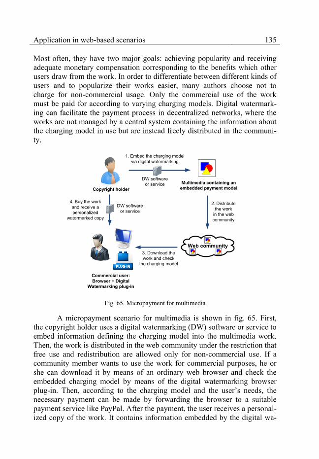
Application in web-based scenarios 135
Most often, they have two major goals: achieving popularity and receiving adequate monetary compensation corresponding to the benefits which other users draw from the work. In order to differentiate between different kinds of users and to popularize their works easier, many authors choose not to charge for non-commercial usage. Only the commercial use of the work must be paid for according to varying charging models. Digital watermark-ing can facilitate the payment process in decentralized networks, where the works are not managed by a central system containing the information about the charging model in use but are instead freely distributed in the communi-ty.
Copyright holder
1. Embed the charging model via digital watermarking
Multimedia containing an embedded payment model
2. Distribute the work
in the web community
Web community
Commercial user: Browser + Digital
Watermarking plug-in
3. Download the work and check
the charging model
4. Buy the work and receive a personalized
watermarked copy
DW software or service
DW software or service
Fig. 65. Micropayment for multimedia
A micropayment scenario for multimedia is shown in fig. 65. First, the copyright holder uses a digital watermarking (DW) software or service to embed information defining the charging model into the multimedia work. Then, the work is distributed in the web community under the restriction that free use and redistribution are allowed only for non-commercial use. If a community member wants to use the work for commercial purposes, he or she can download it by means of an ordinary web browser and check the embedded charging model by means of the digital watermarking browser plug-in. Then, according to the charging model and the user’s needs, the necessary payment can be made by forwarding the browser to a suitable payment service like PayPal. After the payment, the user receives a personal-ized copy of the work. It contains information embedded by the digital wa-

136 Chapter 8
termarking software or service describing the permitted commercial usage. The permission may be time-limited, it may allow only certain types of us-age or it may impose other restrictions.
The digital watermarking technology eliminates the need for a central catalogue linking multimedia works to their license terms and charging mod-els. Keeping license and payment information as close to the protected work as possible – embedded into the work – constitutes a huge advantage in a social network without central management. The scenario illustrates the first and most important role of digital watermarking in the web community – to facilitate the legal use of intellectual property. By stating the license terms of the work and the payment details to any community user who has the digital watermarking browser plug-in, the technology gives any user the opportunity to use the work as intended by the copyright holder.
Nevertheless, in the absence of strict law enforcement mechanisms, some users deliberately choose to violate copyright law and not to pay for commercial usage, although they have all the necessary information to make the payment quickly and with little effort. They may also try to misappropri-ate the shared content and falsely claim copyright over it. Digital watermark-ing itself may not be able to prevent copyright violations but it can assist in their swift discovery by the web community.
Web community
Community members: Browser + Digital
Watermarking plug-in
1. Download multimedia and check the embedded
license information
2. In case of illegal use, exclude the perpetrator from the community
Community member having damaged reputation
Fig. 66. Discovery of copyright violations
A second scenario for the discovery of copyright violations is shown in fig. 66. In the course of their normal activities community members down-load and view multimedia items. If they have the digital watermarking plug-in, they can automatically review the name of the author and the embedded

Application in web-based scenarios 137
license information in each multimedia work, as well. A non-commercial use needs no special license. A commercial use, on the other hand, requires a personalized copy of the multimedia work containing embedded information identifying the commercial user and the permitted type of use. The absence of such information can be swiftly identified by community members view-ing the work. In this case, the reputation of the community member who uses the work without permission is damaged and if such actions continue, the violator can be excluded from the community altogether. Similar repercus-sions threaten users who try to falsely claim copyright over the shared con-tent of other users.
The scenario illustrates how the community, if presented with the proper means, can regulate itself, so that the cost of copyright violations measured in terms of lost reputation becomes high enough to effectively prevent such occurrences. Self-regulation in social networks may be very effective – just as in small villages. If information about immoral acts – in this case about the misappropriation of the intellectual property – becomes publicly available, it is unprofitable for anyone intending to remain in the community to commit crimes even if no formal punishment is carried out. Digital watermarking provides the means to make copyright violations pub-lic knowledge in a decentralized social network. This role of the technology is complementary to the first scenario discussing the fostering of the legal use of intellectual property. Thus, digital watermarking improves the com-pliance to community standards by simultaneously lowering the cost of compliance and increasing the penalties for deliberate violations.
8.3.3 Conclusion
The digital watermarking solution presented in this section enhances the protection of intellectual property rights in web communities. It can be used to facilitate the legal usage of multimedia content according to the cop-yright license chosen by copyright holders. It can also assist in the swift dis-covery and announcement of copyright violations.
Via the prototype implementation of the modular methods described in chapter 6 and the data hiding certification service, web community users can embed high-level copyright information or arbitrary low-level binary information, which can then be analyzed by every web community user by means of the prototype digital watermarking browser plug-in. In this way, both scenarios discussed in the paper can be implemented as a proof-of-concept.

138
Chapter 9 Conclusion
This chapter concludes the book and discusses the contributions made to the data hiding research field. The insights obtained during the re-search, development and testing of the new data hiding concept and methods are summarized and some possible directions for future work are given.
9.1 Contributions
The modular approach to data hiding developed in this book is an in-novative concept with regard to the data hiding research field. It enables the creation of extendable modular data hiding methods specially designed for usage in the World Wide Web. Due to the opportunities for code reuse and due to the easy adaptability to changing user requirements, the new methods can be developed and put into use swiftly and at an affordable price. The web service interfaces and the method features developed explicitly for web-based scenarios help to bring data hiding functionality closer to ordinary web users.
The concept, the implementation, the evaluation and the practical ap-plication of the modular data hiding methods in the World Wide Web consti-tute the major contributions of this book to data hiding research.
9.1.1 Modularity and extensibility
The subdivision of data hiding methods into several encapsulated blocks is the most important innovation of this book. Traditional data hiding methods are monolithic solutions developed for the solution of a specific problem set by the user – typically a large organization or a government agency. In contrast to them, the modular data hiding methods developed in this book consist of building blocks (basic and application-specific modules). Once created, these modules can be reused in different combinations to as-semble new data hiding methods with the exact features needed by end us-ers. In this way, the time, price and the necessary expertise for the develop-ment of new data hiding methods are reduced significantly.
Conclusion 139
It must be kept in mind that the transition from a monolithic structure to a modular one is far from easy. Monolithic data hiding methods can achieve perfect optimization to user requirements. Modular data hiding methods consist of several building blocks and use well-defined interfaces for communication between them. The potential to achieve good optimiza-tion across the building blocks is diminished. The book defines interfaces which enable the encapsulation of each building block but still provide room to achieve good inter-block optimization. As the evaluation of the modular data hiding methods shows, the optimization efforts were successful.
9.1.2 Improved robustness against JPEG transformations
The robustness of the embedded data against different JPEG-related transformations has been an important research topic in data hiding for some time. It is an important method feature for the successful application of data hiding methods in web-based scenarios.
The book develops a new method for the achievement of robustness against JPEG compression, decompression and recompression. This method is encapsulated as a separate building block – the DCTHiderEngine – usable by the modular data hiding methods.
The main focus is the achievement of an error-free retrieval of arbi-trary embedded data after the application of JPEG-related transformations by common image processing software. In this way, maximum reliability of the embedded data can be guaranteed. The end users can perform common JPEG transformations on the images without destroying even one bit of the em-bedded data. In addition, the other building blocks of the modular data hid-ing methods that wish to use this feature may do so without having to cope with any unnecessary restrictions imposed by it. The robustness against JPEG transformations remains transparent and reliable for both end users and other data hiding building blocks.
9.1.3 Data hiding as a certification service
Another important contribution of this book is the data hiding certifi-cation service created to enhance the security in different web-related scenar-ios. It aims at achieving an easy integration of the modular data hiding meth-ods with the traditional IT infrastructure present in the World Wide Web – web servers, application servers, browsers, automated crawlers, etc.
By using web service interfaces, the data hiding certification service allows clients to embed a security signature inside the multimedia content
140 Chapter 9
before publishing the multimedia files on the Internet. Later, these signatures can be verified by the service for a variety of purposes such as the prevention of phishing or the discovery of copyright violations.
Traditional data hiding methods are developed with a single applica-tion in mind – most often for a single large customer. They are expensive to develop and difficult to adapt to new conditions. In contrast, the data hiding certification service relies on the easily adaptable modular data hiding meth-ods. It builds an additional layer whose express purpose is to provide a flexi-ble link between the specialized functionality of data hiding and real web-related scenarios needing better security solutions. The service is provided in a simple and standardized way, which facilitates its usage by different cli-ents. In this way, data hiding functionality can be offered as a typical soft-ware service which can be used and paid for by anyone – from small and medium-sized enterprises to large corporations.
9.2 Future work
The main benefits of the modular approach to data hiding lie in the adaptability of the modular data hiding methods to changing conditions – new user requirements, new image formats or new application areas – and in the ease of integration – by means of web services.
In order to maximize the adaptability, a library of pre-created stand-ard building blocks for the modular data hiding methods is needed. Basic building blocks providing robustness against other web-related lossy com-pression formats such as GIF or PNG or basic image transformations such as cropping or scaling are essential. More sophisticated blocks may provide support for complex steganographic or digital watermarking functionality such as the ability to recover modified multimedia areas. The creation of an extensive library of building blocks providing support for popular data hid-ing features is an important precondition for the practical success of the modular data hiding methods.
Another important area needing further attention is the creation of a set of standardized web services which can be used in a variety of web-based scenarios. The data hiding certification service provides the first prototype offering a couple of important generalized web service operations for the embedding and verification of multimedia signatures. Such web services should be defined and implemented for other data hiding applications, as well. They should be organized according to a common scheme with a later international standardization in view.
Conclusion 141
The enhancement of the modular architecture of the data hiding methods may constitute another important part of the future research. At the moment, the modular data hiding methods consist of the combination of two modules – a basic and an application-specific module. This division may be too coarse for some applications. Ideally, a different number of modules – each one responsible for a different method feature – should be able to work together to form a new data hiding method. It would provide maximum reus-ability of the existing code and excellent adaptability to changing user re-quirements.
Multimedia content is an integral part of the World Wide Web. Data hiding provides an effective protection for this content. In the near future, it will become an indispensable part of the security mechanisms keeping the World Wide Web safe.
142
References
[1] Herodotus. Histories, Book 5, 440 B.C. [2] Peterson, J. (1997). Steganographia (Secret Writing), by Johannes
Trithemius. [Online]. URL: http://www.esotericarchives.com/tritheim/stegano.htm (accessed May 9, 2009).
[3] Deutsche Bundesbank. Bundesbank – Currency – Euro-Banknotes – Security features. [Online]. URL: http://www.bundesbank.de/bargeld/bargeld_banknoten_sicherheitsmerkmale.en.php (accessed May 9, 2009).
[4] Science Kids. Create invisible ink with lemon juice. [Online]. URL: http://www.sciencekids.co.nz/experiments/invisibleink.html (accessed May 9, 2009).
[5] Trimm, H. Forensics the easy way, 1st ed., Barron’s educational series, 2005.
[6] Cox, I. J., M. Miller, J. Bloom, J. Fridrich, and T. Kalker. Digital Watermarking and Steganography, 2nd ed., Morgan Kaufmann Publishers, 2008.
[7] Lin, E. and J. Delp. A Review of Data Hiding in Digital Images. In: Proceedings of the Image Processing, Image Quality, Image Capture Systems Conference (PICS '99), Savannah, Georgia, 1999, p. 274–278.
[8] Curran, K. and K. Bailey. An Evaluation of Image Based Steganography Methods. In: International Journal of Digital Evidence, vol. 2, no. 2, 2003.
[9] Cole, E. Hiding in Plain Sight: Steganography and the Art of Covert Communication, 1st ed., John Wiley & Sons, 2003.
[10] Interagency Working Group (IWG) On Cyber Security and Information Assurance (CSIA) (2006). Federal Plan for Cyber Security and Information Assurance Research and Development. [Online]. URL: http://www.nitrd.gov/pubs/csia/csia_federal_plan.pdf (accessed May 9, 2009).
[11] Feng, D., W. Siu, and H. Zhang. Multimedia Information Retrieval
References 143
and Management, 1st ed., Springer, 2003. [12] Lim, Y., C. Xu, and D. Feng. Web based image authentication using
invisible Fragile watermark. In: ACM International Conference Proceeding Series, Proceedings of the Pan-Sydney area workshop on Visual information processing, vol. 11, 2001, p. 31–34.
[13] Rey, C. and J Dugelay. A Survey of Watermarking Algorithms for Image Authentication. In: EURASIP Journal on Applied Signal Processing, vol. 6, 2002, p. 613–621.
[14] Lu, C. Multimedia Security: Steganography and Digital Watermarking Techniques for Protection of Intellectual Property, 1st ed., Idea Group Publishing, 2005.
[15] Stallings, W. Cryptography and Network Security Principles and Practices, 4th ed., Prentice Hall, 2005.
[16] Mao, W. Modern Cryptography: Theory and Practice, 1st ed., Prentice Hall, 2003.
[17] Zeng, W., H. Yu, and C. Lin. Multimedia security technologies for digital rights management, 1st ed., Elsevier, 2006.
[18] Peinado, M., F. Petitcolas, and D. Kirovski. Digital rights management for digital cinema. In: Multimedia Systems, vol. 9, no. 3, September 2003.
[19] Electronic Privacy Information Center. Cryptography Policy. [Online]. URL: http://www.epic.org/crypto/ (accessed May 9, 2009).
[20] World Wide Web Consortium. About W3C: Goals. [Online]. URL: http://www.w3.org/Consortium/mission (accessed May 9, 2009).
[21] Miniwatts Marketing Group. Internet Usage Statistics. [Online]. URL: http://www.internetworldstats.com/stats.htm (accessed May 9, 2009).
[22] O'Reilly, T. (2005). What is Web 2.0. [Online]. URL: http://www.oreillynet.com/pub/a/oreilly/tim/news/2005/09/30/what-is-web-20.html?page=1 (accessed May 9, 2009).
[23] O'Reilly, T. (2006). Web 2.0 Compact Definition: Trying Again. [Online]. URL: http://radar.oreilly.com/2006/12/web-20-compact-definition-tryi.html (accessed May 9, 2009).
[24] O'Reilly, T. (2006). Harnessing Collective Intelligence. [Online]. URL: http://radar.oreilly.com/2006/11/harnessing-collective-intellig.html (accessed May 9, 2009).
[25] Peng, Y. and Q. Wu. Secure Communication and Access Control for Web Services Container. In: Fifth International Conference on Grid
144 References
and Cooperative Computing (GCC), 2006, p. 412–415. [26] Zarandioon, S., Y. Danfeng, and V. Ganapathy. OMOS: A Framework
for Secure Communication in Mashup Applications. In: Computer Security Applications Conference, 2008, p. 355–364.
[27] Farley, M. Web 2.0, wikis, and the IP Community. In: Journal of Intellectual Property Law & Practice, vol. 2, no. 4, 2007.
[28] Gil, R., R. Tous, and J. Delgado. Managing intellectual property rights in the WWW: patterns and semantics. In: First International Conference on Automated Production of Cross Media Content for Multi-Channel Distribution, 2005.
[29] Garofalakis, J., P. Kappos, S. Sirmakessis, and G. Tzimas. Digital Data Processing For Intellectual Property Rights Preservation Over World Wide Web. In: 13th International Conference on Digital Signal Processing Proceedings, vol. 2, 1997, p. 833–836.
[30] Backes, M. and C. Cachin. Public-key steganography with active attacks. In: 2nd Theory of Cryptography Conference (TCC), vol. 3378 of Lecture Notes in Computer Science, 2005, p. 210–226.
[31] Anderson, R. J. and F. Petitcolas. On the limits of steganography. In: IEEE Journal on Selected Areas in Communications, vol. 16, no. 4, 1998, p. 474–481.
[32] Westfeld, A. Steganalysis in the Presence of Weak Cryptography and Encoding. In: Digital Watermarking. 5th International Workshop (IWDW), vol. LNCS 4283, Jeju Island, Korea, 2006, p. 19–34.
[33] Katzenbeisser, S. and F. Petitcolas. Information Hiding Techniques for Steganography and Digital Watermarking, 1st ed., Artech House, 2000.
[34] Kipper, G. Investigator's Guide to Steganography, 1st ed., Auerbach Publications, 2004.
[35] Anderson, R. J., R. M. Needham, and A. Shamshir. The Steganographic File System. In: Second International Workshop on Information Hiding, vol. 1525 of Lecture Notes in Computer Science, Portland, 1998, p. 73–82.
[36] Fridrich, J. and M. Goljan. Protection of Digital Images Using Self Embedding. In: Symposium on Content Security and Data Hiding in Digital Media, New Jersey Institute of Technology, 1999.
[37] Friedman, G. The Trustworthy Digital Camera: Restoring Credibility to the Photographic Image. In: IEEE Transactions on Consumer
References 145
Electronics, vol. 39, no. 4, 1993, p. 905–910. [38] Meyer, S. (2008). Midnight Sun: Edward's Version of Twilight.
[Online]. URL: http://www.stepheniemeyer.com/midnightsun.html (accessed May 9, 2009).
[39] Voloshynovskiy, S., F. Deguillaume, O. Koval, and T. Pun. Information-theoretic Data-hiding: Recent Achievements and Open Problems. In: International Journal of Image and Graphics, vol. 5, no. 1, 2005, p. 1–31.
[40] Lin, E. and E. Delp. A Review of Fragile Image Watermarks. In: Proceedings of the Multimedia and Security Workshop (ACM Multimedia '99), 1999, p. 25–29.
[41] Pennebaker, W. B. and J. L. Mitchell. JPEG Still Image Data Compression Standard, 1st ed., Van Rostrand Reinhold, New York, 1993.
[42] Hamilton, E. (1992, September). JPEG File Interchange Format. [Online]. URL: http://www.w3.org/Graphics/JPEG/jfif3.pdf (accessed May 9, 2009).
[43] Hartung, F. and M. Kutter. Multimedia watermarking techniques. In: Proceedings of the IEEE, vol. 87, no. 7, July 1999, p. 1079–1107.
[44] Upham, D. (2009). JSteg. [Online]. URL: http://zooid.org/~paul/crypto/jsteg/ (accessed May 9, 2009).
[45] Wayner, P. Disappearing Cryptography, 2nd ed., Morgan Kaufmann Publishers, 2002.
[46] Wu, M., Z. Zhu, and S. Jin. A New Steganalytic Algorithm for Detecting Jsteg. In: Lecture Notes in Computer Science, vol. 3619, 2005, p. 1073–1082.
[47] Provos, N. and P. Honeyman. Detecting Steganographic Content on the Internet. In: Internet Society Network and Distributed System Security Symposium (ISOC NDSS), San Diego, California, 2002.
[48] Zhao, J. and E. Koch. Towards Robust and Hidden Image Copyright Labeling. In: IEEE Workshop on Nonlinear Signal and Image Processing, Neos Marmaras, Greece, 1995.
[49] Zhao, J. and E. Koch. Embedding Robust Labels into Images for Copyright Protection. In: International Congress on Intellectual Property Rights for Specialized Information, Knowledge and New Technologies, Vienna, Austria, 1995.
[50] O'Ruanaidh, J. J., W. J. Dowling, and F. M. Boland. Watermarking
146 References
digital images for copyright protection. In: Vision, Image and Signal Processing, IEEE Proceedings, vol. 143, no. 4, 1996, p. 250–256.
[51] Cox, I. J., J. Kilian, T. Leighton, and T. Shamoon. Secure Spread Spectrum Watermarking for Multimedia. In: IEEE Transactions on Image Processing, vol. 6, no. 12, 1997, p. 1673–1687.
[52] Wu, M. and B. Liu. Watermarking for image authentication. In: IEEE International Conference on Image Processing, vol. 2, Chicago, Illinois, 1998, p. 437–441.
[53] Lin, C.-Y. and S.-F. Chang. Semi-fragile watermarking for authenticating JPEG visual content. In: SPIE International Conference on Security and Watermarking of Multimedia Contents II, vol. 3971, San Jose, California, USA, 2000.
[54] Lin, C.-Y. and S.-F. Chang. A Robust Image Authentication Method Distinguishing JPEG Compression from Malicious Manipulation. In: IEEE Transactions on Circuits and Systems of Video Technology, vol. 11, no. 2, 2001.
[55] Sun, Q., S. Ye, C.-J. Lin, and S.-F. Chang. A Crypto Signature Scheme for Image Authentication over Wireless Channel. In: International Journal of Image and Graphics, special issue on Image Data Hiding, vol. 5, no. 1, 2005.
[56] Provos, N. Defending against statistical steganalysis. In: 10th USENIX Security Symposium, 2001.
[57] Provos, N. (2008, July). OutGuess – universal Steganography. [Online]. URL: http://www.outguess.org/ (accessed May 09, 2009).
[58] Westfeld, A. F5 – A Steganographic Algorithm. In: Proceedings of the 4th International Workshop on Information Hiding, Lecture Notes In Computer Science, vol. 2137, 2001, p. 289–302.
[59] Crandall, R. (1998). Some Notes on Steganography. Posted on Steganography. Posted on Steganography Mailing List. [Online]. URL: http://os.inf.tu-dresden.de/westfeld/crandall.pdf (accessed May 9, 2009).
[60] Fridrich, J., M. Goljan, and D. Hogea. Attacking the OutGuess. In: Proceedings of the ACM Workshop on Multimedia and Security, Juan-les-Pins, France, 2002.
[61] Fridrich, J., M. Goljan, and D. Hogea. Steganalysis of JPEG Images: Breaking the F5 Algorithm. In: 5th Information Hiding Workshop, Noordwijkerhout, the Netherlands, 2002, p. 310–323.
References 147
[62] Chang, C.-C., T.-S. Chen, and L.-Z. Chung. A steganographic method based upon JPEG and quantization table modification. In: Information Sciences - Informatics and Computer Science, vol. 141, no. 1–2, 2002, p. 123–138.
[63] Fridrich, J. Image Watermarking for Tamper Detection. In: IEEE International Conference on Image Processing (ICIP), Chicago, 1998.
[64] Fridrich, J. Methods for Detecting Changes in Digital Images. In: Proceedings of The 6th IEEE International Workshop on Intelligent Signal Processing and Communication Systems (ISPACS), Melbourne, Australia, 1998, p. 173–177.
[65] Fridrich, J. and M. Goljan. Images with Self-Correcting Capabilities. In: IEEE International Conference on Image Processing, Kobe, Japan, 1999.
[66] Fridrich, J., M. Goljan, and R. Du. Invertible Authentication Watermark for JPEG Images. In: International Symposium on Information Technology (ITCC), Las Vegas, Nevada, 2001, p. 223–227.
[67] Fridrich, J., M. Goljan, and R. Du. Lossless Data Embedding – New Paradigm in Digital Watermarking. In: Special Issue on Emerging Applications of Multimedia Data Hiding, 2002, p. 185–196.
[68] Fridrich, J., M. Goljan, Q. Chen, and V. Pathak. Lossless Data Embedding with File Size Preservation. In: Proceedings EI SPIE, San Jose, CA, 2004.
[69] Weisstein, E. W.. Arnold's Cat Map. [Online]. URL: http://mathworld.wolfram.com/ArnoldsCatMap.html (accessed May 9, 2009).
[70] Zhao, R.-M., H. Lian, H.-W. Pang, and B.-N. Hu. A Watermarking Algorithm by Modifying AC Coefficies in DCT Domain. In: International Symposium on Information Science and Engieering (ISISE), vol. 2, Shanghai, China, 2008, p. 159–162.
[71] Zhang, X.-P., K. Li, and X. Wang. A Novel Look-Up Table Design Method for Data Hiding With Reduced Distortion. In: IEEE Transactions on Circuits and Systems for Video Technology, vol. 18, no. 6, 2008, p. 769–776.
[72] Li, Q. and I. J. Cox. Using Perceptual Models to Improve Fidelity and Provide Resistance to Valumetric Scaling for Quantization Index Modulation Watermarking. In: IEEE Transactions on Information Forensics and Security, vol. 2, no. 2, 2007.
148 References
[73] Sun, X., J. Liu, J. Sun, N. Yang, and S. Wu. An Improved Adaptive QIM Watermark Iterative Algorithm. In: Intelligent Information Hiding and Multimedia Signal Processing (IIHMSP), Harbin, China, 2008, p. 748–751.
[74] Izadinia, H., F. Sadeghi, and M. Rahmati. A New Steganographic Method Using Quantization Index Modulation. In: International Conference on Computer and Automation Engineering (ICCAE), 2009, p. 181–185.
[75] Costa, M. Writing on dirty paper. In: IEEE Transactions on Information Theory, vol. 29, no. 3, 1983, p. 439–441.
[76] Chen, B. and G. W. Wornell. Quantization Index Modulation: A Class of Provably Good Methods for Digital Watermarking and Information Embedding. In: IEEE Transactions on Information Theory, vol. 47, no. 4, 2001, p. 1423–1443.
[77] Watson, A. B. DCT quantization matrices optimized for individual images. In: Human Vision, Visual Processing, and Digital Display IV, vol. SPIE-1913, 1993, p. 202–216.
[78] Yu, Y.-H., C.-C. Chang, and Y.-C. Hub. Hiding secret data in images via predictive coding. In: Pattern Recognition, vol. 38, no. 5, 2005, p. 691–705.
[79] Steganos GmbH (2009, August). Steganos Privacy Suite: Overview. [Online]. URL: http://www.steganos.com/us/products/data-security/privacy-suite/overview/
[80] Latham, A. (1999, August). Steganography. [Online]. URL: http://linux01.gwdg.de/~alatham/stego.html (accessed August 20, 2009).
[81] NeoByte Solutions. Invisible Secrets 4. [Online]. URL: http://www.invisiblesecrets.com/ (accessed August 20, 2009).
[82] Digimarc Corporation. Digimarc. [Online]. URL: https://www.digimarc.com/ (accessed May 9, 2009).
[83] Digimarc Corporation (2009, May). Digimarc Search Service. [Online]. URL: https://www.digimarc.com/solutions/enterprise_tracking.asp
[84] CSG Copyright Services GmbH & Co. KG. Photopatrol.eu. [Online]. URL: http://www.photopatrol.eu/ (accessed Aug. 20, 2009).
[85] Fraunhofer-Institut SIT (2009, Aug.). Fraunhofer-Institut SIT. [Online]. URL: http://www.sit.fraunhofer.de/
References 149
[86] Krolupper, F. (2008). http://www.adptools.com/. (accessed August 20, 2009).
[87] Krolupper, F. (2008). Image Spider. [Online]. URL: http://www.adptools.com/signmyimage/eng/spider.html (accessed August 20, 2009).
[88] Phibit Software (2009). Icemark Overview. [Online]. URL: http://www.phibit.com/icemark/ (accessed August 20, 2009).
[89] Alpha Tec Ltd. (2009, August). Eikonamark. [Online]. URL: http://www.alphatecltd.com/watermarking/eikonamark/eikonamark.html
[90] Alpha Tec Ltd.. Alphacrawler. [Online]. URL: http://www.alphatecltd.com/watermarking/alphacrawler.html (accessed August 20, 2009).
[91] DataMark Technologies (2009). DataMark Technologies. [Online]. URL: http://www.datamark.com.sg/ (accessed August 20, 2009).
[92] Chappel, D. Understanding .NET, 2nd ed., Addison-Wesley, 2006. [93] Duffy, J. Professional .NET Framework 2.0, 1st ed., Wrox Press,
2006. [94] Hoang, L. and T. Thuan. .NET Framework Essentials, 3rd ed.,
O’Reilly, 2003. [95] Novell, Inc.. The Mono project. [Online]. URL: http://www.mono-
project.com (accessed May 9, 2009). [96] Strutz, T. Bilddatenkompression: Grundlagen, Codierung, JPEG,
MPEG, Wavelets, 2nd ed., Vieweg, 2002. [97] Levkowitz, H. Color Theory and Modeling for Computer Graphics,
Visualization, and Multimedia Applications, 1st ed., Kluwer Academic Publishers, 1997.
[98] Bracewell, R. The Fourier Transform and its Applications, 3rd ed., McGraw-Hill, 2000.
[99] Moon, T. Error Correction Coding. Mathematical Methods and Algorithms, 1st ed., John Wiley & Sons, 2005.
[100] van Lint, J. H. Introduction to Coding Theory, 3rd ed., Springer, 1999. [101] Knuth, D. The Art of Computer Programming, 3rd ed., Addison-
Wesley, vol. 2, 1998. [102] Marsaglia, G. Random number generators. In: Journal of Modern
Applied Statistical Methods, vol. 2, no. 1, May 2003, p. 2–13.
150 References
[103] Richardson, I. E. H.264 and MPEG-4 Video Compression. Video Coding for Next-generation Multimedia., 1st ed., John Wiley & Sons, 2003.
[104] Gonzalez, R. and R. Woods. Digital Image Processing, 2nd ed., Prentice Hall, 2002.
[105] Rao, K. R. and P. C. Yip. The Transform and Data Compression Handbook, 1st ed., CRC Press, 2001.
[106] Provos, N. and P. Honeyman. Hide and seek: an introduction to steganography. In: IEEE Security & Privacy, vol. 1, no. 3, May–June 2003, p. 32–44.
[107] Provos, N. (2008). Steganography Detection with Stegdetect. [Online]. URL: http://www.outguess.org/detection.php (accessed May 9, 2009).
[108] Grgic, S., M. Mrak, and M. Grgic. Comparison of JPEG Image Coders. In: Proceedings of the 3rd International Symposium on Video Processing and Multimedia Communications (VIPromCom-2001), Zadar, Croatia, 2001, p. 79–85.
[109] Dsouza, K. (2008, August). Run Greasemonkey User Scripts in IE, Opera and Safari. [Online]. URL: http://techie-buzz.com/tips-and-tricks/greasemonkey-alternatives-for-ie-opera-and-safari.html (accessed May 9, 2009).
[110] Technical Standardization Committee on AV & IT Storage Systems and Equipment (2002, April). JEITA CP-3451 – Exchangeable image file format for digital still cameras: Exif Version 2.2. [Online]. URL: http://www.kodak.com/global/plugins/acrobat/en/service/digCam/exifStandard2.pdf (accessed May 9, 2009).