Embed Size (px)
Citation preview

A NEW INSTRUMENT FOR ROUTINE OPTICAL TESTING OF GENERAL ASPHERICS
Peter M. EmmelTropel Inc.
Fairport, New York 14450and
Kang M. LeungHoneywell Corporate Materials Sciences Center
Bloomington, Minnesota 55420
Abstract
A unique and versatile laser interferometer has been jointly developed by Honeywell,Tropel and the University of Arizona. The system is designed for routine non -contact test-ing of aspheric optical surfaces (using a Computer- Generated Hologram [CGH] to provide theaspheric component of the reference wavefront) while retaining the features and capabili-ties of the standard Tropel Vertical Interferometer. Thus it is capable of measuringradius and /or optical figure of spheres, flats, conics and general aspherics. The instru-ment provides convenient interchangeability among Fizeau, Twyman- Green, CGH and LateralShearing modes of operation in a single compact unit. It is also capable of direct inter-facing with a computer for wavefront measurement or analysis. The operation of the systemis described and data is presented from a CGH test of an f/2 paraboloid (using a sphericaltest wavefront) for which independent comparative data is also given.
Introduction
Precision lens molding and, more recently, ultraprecision machining techniques arenarrowing the gap in production costs between spherical and non -spherical optical surfaces.Indeed, from the fabrication standpoint, in either of these technologies, there is littledifference between making a sphere and making an asphere. However, when it comes tomeasuring the surface figure, aspherics have always posed serious problems. The rapidcommercialization of aspheric manufacturing technology requires a corresponding develop-ment in measurement capability.
Interferometric equipment for non -contact testing of various optical surfaces has beenin use for many years. However, with a few exceptions, commercially available instrumentshave been limited to the testing of flats and concave spheres. The exceptions are thoseoffering a variety of focusing lenses, with reasonably large apertures, for testing a use-ful range of convex spheres. Using simple auxilliary optics, most available instrumentscan also test conic surfaces such as paraboloids, ellipsoids and hyperboloids. Generalaspherics, however, with more than a few waves departure from the nearest conic, usuallyexceed the capability of these instruments to even view, let alone accurately measure.
The literature contains many laboratory setups for overcoming the difficulties in test-ing aspherics.(1,2) The most promising are those using holographic techniques to generatea reference wavefront which matches the wavefront reflected by the aspheric test surface.(3)The resulting interference fringes are interpreted in the same way as those in convention-al two -beam interferometers.
Another method for testing aspherics is lateral wavefront shearing, where the test beamis divided into two identical beams with a slight lateral displacement. Interference be-tween these displaced beams produces a fringe pattern which, for small displacements, isdirectly related to the slope of the wavefront, but only indirectly related to its totaldepth. Obtaining accurate depth information from such a fringe pattern requires numericalanalysis best performed by a computer.(4)
This paper describes the implementation of both of these techniques - holography andshearing - in a commercially oriented laser interferometer, thus adding aspherics to itsother surface testing capabilities. The interferometer was developed jointly by Honeywell,Tropel and the University of Arizona. The intent was to provide a single instrument ver-satile enough to satisfy the needs of several groups for a convenient interferometric meansof testing a variety of optical materials and surfaces including aspherics. Since thesegroups were engaged in developing various production technologies, the system had to bepractical in routine production -level use where ease of setup and adjustment are keyfactors. It was also intended to be adaptable to possible future needs, such as real -timeholography and direct computer interfacing.
SPIE Vol. 171 Optical Components: Manufacture & Evaluation (1979) / 93
A NEW INSTRUMENT FOR ROUTINE OPTICAL TESTING OF GENERAL ASPHERICS
Peter M. EmmelTropel Inc.
Fairport, New York 14450and
Kang M. LeungHoneywell Corporate Materials Sciences Center
Bloomington, Minnesota 55420
Abstract
A unique and versatile laser interferometer has been jointly developed by Honeywell, Tropel and the University of Arizona. The system is designed for routine non-contact test ing of aspheric optical surfaces (using a Computer-Generated Hologram [CGH] to provide the aspheric component of the reference wavefront) while retaining the features and capabili ties of the standard Tropel Vertical Interferometer. Thus it is capable of measuring radius and/or optical figure of spheres, flats, conies and general aspherics. The instru ment provides convenient interchangeability among Fizeau, Twyman-Green, CGH and Lateral Shearing modes of operation in a single compact unit. It is also capable of direct inter facing with a computer for wavefront measurement or analysis. The operation of the system is described and data is presented from a CGH test of an f/2 paraboloid (using a spherical test wavefront) for which independent comparative data is also given.
Introduction
Precision lens molding and, more recently, ultraprecision machining techniques are narrowing the gap in production costs between spherical and non-spherical optical surfaces. Indeed, from the fabrication standpoint, in either of these technologies, there is little difference between making a sphere and making an asphere. However, when it comes to measuring the surface figure, aspherics have always posed serious problems. The rapid commercialization of aspheric manufacturing technology requires a corresponding develop ment in measurement capability.
Interferometric equipment for non-contact testing of various optical surfaces has been in use for many years. However, with a few exceptions, commercially available instruments have been limited to the testing of flats and concave spheres. The exceptions are those offering a variety of focusing lenses, with reasonably large apertures, for testing a use ful range of convex spheres. Using simple auxilliary optics, most available instruments can also test conic surfaces such as paraboloids, ellipsoids and hyperboloids. General aspherics, however, with more than a few waves departure from the nearest conic, usually exceed the capability of these instruments to even view, let alone accurately measure.
The literature contains many laboratory setups for overcoming the difficulties in test ing aspherics.(1>2) The most promising are those using holographic techniques to generate a reference wavefront which matches the wavefront reflected by the aspheric test surface.'-^) The resulting interference fringes are interpreted in the same way as those in convention al two-beam interferometers.
Another method for testing aspherics is lateral wavefront shearing, where the test beam is divided into two identical beams with a slight lateral displacement, Interference be tween these displaced beams produces a fringe pattern which, for small displacements, is directly related to the slope of the wavefront, but only indirectly related to its total depth. Obtaining accurate depth information from such a fringe pattern requires numerical analysis best performed by a computer.(4)
This paper describes the implementation of both of these techniques - holography and shearing - in a commercially oriented laser interferometer, thus adding aspherics to its other surface testing capabilities. The interferometer was developed jointly by Honeywell, Tropel and the University of Arizona. The intent was to provide a single instrument ver satile enough to satisfy the needs of several groups for a convenient interferometric means of testing a variety of optical materials and surfaces including aspherics. Since these groups were engaged in developing various production technologies, the system had to be practical in routine production-level use where ease of setup and adjustment are key factors. It was also intended to be adaptable to possible future needs, such as real-time holography and direct computer interfacing.
SPIE Vol. 171 Optical Components: Manufacture & Evaluation (1979) / 93
Downloaded From: http://spiedigitallibrary.org/ on 03/21/2013 Terms of Use: http://spiedl.org/terms
EMMEL, LEUNG
The Tropel Model 4000 was chosen as a starting point because of its convenient verticaltest beam and its Fizeau testing capability for flats, spheres and conics. The internallayout of the Model 4000 along with its single- frequency HeNe laser and its relativelysmall internal beam diameter, all proved to be particularly advantageous.
The interferometer design was modified to allow use of computer -generated holograms (CGH)and lateral wavefront shearing for testing of known and unknown aspherics having up toseveral hundred waves departure from the nearest sphere. The design also permits the gener-ation of real -time holograms in cases where a master aspheric surface is available. Therange of radius and figure measurement was extended to 450mm and a motor drive was added tothe vertical slide. All other features of the standard interferometer were retained.
Several additional features were necessary in order to implement the CGH mode of opera-tion. The most important of these was that a real image of the test surface had to be pro-jected onto the hologram plane. Failure to satisfy this condition causes systematicmeasurement errors which increase in proportion to the asphericity of the surface undertest. Accuracy was maintained over the full range of radii by providing variable (stepwise)magnification and independent focusing between the test surface and the hologram plane.
System Description
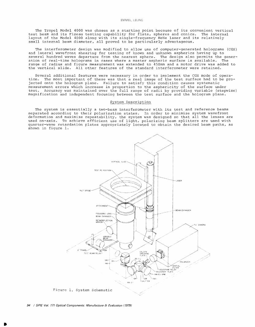
The system is essentially a two -beam interferometer with its test and reference beamsseparated according to their polarization states. In order to minimize system wavefrontdeformation and maximize repeatability, the system was designed so that all the lenses areused on -axis. To achieve efficient use of light, polarizing beam splitters are used withquarter -wave retardation plates appropriately located to obtain the desired beam paths, asshown in figure 1.
TEST PC POSITION
TILT STAGELam_
VERTICAL SLIDE
ATTACHMENT
FOCUSSING LENS
BEAM EXPANDER
LASER
__,-BEAM EXPANDER
RETRORE F L ECTIONMIRROR
TV CAMERA
VARIABLEBEAM
>- EXPANDER
TRAVEL
TEST BEAM RELAY-CALCITESHEARINGPLATE
SPATIALFILTER
HOLOGRAM RELAY-HOLOGRAM PLATE
a--HW ADJ ARM\`RM -I
Figure 1, System Schematic
RM-2'
94 / SPIE Vol. 171 Optical Components: Manufacture & Evaluation (1979)
SHUTTER
POLARIZER
EMMEL, LEUNG
The Tropel Model 4000 was chosen as a starting point because of its convenient vertical test beam and its Fizeau testing capability for flats, spheres and conies. The internal layout of the Model 4000 along with its single-frequency HeNe laser and its relatively small internal beam diameter, all proved to be particularly advantageous.
The interferometer design was modified to allow use of computer-generated holograms (CGH) and lateral wavefront shearing for testing of known and unknown aspherics having up to several hundred waves departure from the nearest sphere. The design also permits the gener ation of real-time holograms in cases where a master aspheric surface is available. The range of radius and figure measurement was extended to 450mm and a motor drive was added to the vertical slide. All other features of the standard interferometer were retained.
Several additional features were necessary in order to implement the CGH mode of opera tion. The most important of these was that a real image of the test surface had to be pro jected onto the hologram plane. Failure to satisfy this condition causes systematic measurement errors which increase in proportion to the asphericity of the surface under test. Accuracy was maintained over the full range of radii by providing variable (stepwise) magnification and independent focusing between the test surface and the hologram plane.
System Description
The system is essentially a two-beam interferometer with its test and reference beams separated according to their polarization states. In order to minimize system wavefront deformation and maximize repeatability, the system was designed so that all the lenses are used on-axis. To achieve efficient use of light, polarizing beam splitters are used with quarter-wave retardation plates appropriately located to obtain the desired beam paths, as shown in figure 1.
6" TRAVEL--7
TEST BEAM RELAY^
TV CAMERA
Figure 1. System Schematic
94 / SPIE Vol. 171 Optical Components: Manufacture 8- Evaluation (1979)
Downloaded From: http://spiedigitallibrary.org/ on 03/21/2013 Terms of Use: http://spiedl.org/terms

A NEW INSTRUMENT FOR ROUTINE OPTICAL TESTING OF GENERAL ASPHERICS
The layout is best described by identifying its five "arms ": the source arm, the testarm, the relay arm, the reference arm, and the viewing arm. In the source arm the linearlypolarized beam is expanded and collimated. Its plane of polarization is rotated accordingto the half -wave plate (HW) adjustment. The first polarizing beamsplitter (BS -1) reflectsthe S- polarized component, which becomes the reference beam, and transmits the P- polarizedcomponent, which becomes the test beam. Quarter -wave plates (QW), located in the test andrelay arms, control the polarization of the test beam and thus determine whether it istransmitted or reflected on each succeeding encounter with BS -1.
The vertically oriented test arm consists of a series of interchangeable beam expandingand focusing lenses. A particular combination is chosen to provide an appropriate spheri-cal (or plane) wavefront to nearly match the test surface. The test surface, positionedfor the best "fit" to this wavefront, reflects the beam back through the test arm optics.Any mismatch between the test surface and the illuminating wavefront is captured as adeformation of the returning wavefront. Three beam sizes may be selected by adjusting thevariable beam expander, which also varies the viewing magnification.
The returning test beam is reflected by BS -1 and enters the relay arm. The relay is aretroreflector consisting of a lens with a plane mirror located at its focus. It reflectsa real image of the test surface back through the beamsplitter toward the hologram in theviewing arm. The relay is adjusted along its track to bring the test surface into sharpfocus at the hologram plane, without affecting its magnification.
In the space between the two beamsplitters the test and reference beams are recombined,but they are still orthogonally polarized. They are separated by the second beamsplitter(BS -2), which transmits the reference beam and reflects the test beam along the axis of theviewing arm. The viewing arm contains the hologram, a second relay lens and a closed cir-cuit television camera. Figure 2 gives a more detailed view of the reference and viewingarms of the interferometer. The path of the reference beam is determined by two sets ofquarter -wave plates and adjustable plane mirrors (RM -1 and RM -2). Adjustment of themirrors gives the necessary reference beam angle at the hologram.
ZERO -ORDER REF
BS-2
COMBINED TESTAND REF BEAMS -C
TAZERO-ORDER TEST 8c
FIRST-ORDER REFtyII.QWRM-I
-VIDICON
i(.ANALYZER
(SPATIAL FILTER
-HOLOGRAM RELAY LENS
COMPUTER GENERATEDHOLOGRAM
QW
RM-2
Figure 2. Viewing Arm Schematic
SPIE Vol. 171 Optical Components: Manufacture & Evaluation (1979) / 95
A NEW INSTRUMENT FOR ROUTINE OPTICAE TESTING OF GENERAE ASPHERICS
The layout is best described by identifying its five "arms": the source arm, the test arm, the relay arm, the reference arm, and the viewing arm. In the source arm the linearly polarized beam is expanded and collimated. Its plane of polarization is rotated according to the half-wave plate (HW) adjustment. The first polarizing beamsplitter (BS-1) reflects the S-polarized component, which becomes the reference beam, and transmits the P-polarized component, which becomes the test beam. Quarter-wave plates (QW), located in the test and relay arms, control the polarization of the test beam and thus determine whether it is transmitted or reflected on each succeeding encounter with BS-1.
The vertically oriented test arm consists of a series of interchangeable beam expanding and focusing lenses. A particular combination is chosen to provide an appropriate spheri cal (or plane) wavefront to nearly match the test surface. The test surface, positioned for the best "fit" to this wavefront, reflects the beam back through the test arm optics. Any mismatch between the test surface and the illuminating wavefront is captured as a deformation of the returning wavefront. Three beam sizes may be selected by adjusting the variable beam expander, which also varies the viewing magnification.
The returning test beam is reflected by BS-1 and enters the relay arm. The relay is a retroreflector consisting of a lens with a plane mirror located at its focus. It reflects a real image of the test surface back through the beamsplitter toward the hologram in the viewing arm. The relay is adjusted along its track to bring the test surface into sharp focus at the hologram plane, without affecting its magnification.
In the space between the two beamsplitters the test and reference beams are recombined, but they are still orthogonally polarized. They are separated by the second beamsplitter (BS-2), which transmits the reference beam and reflects the test beam along the axis of the viewing arm. The viewing arm contains the hologram, a second relay lens and a closed cir cuit television camera. Figure 2 gives a more detailed view of the reference and viewing arms of the interferometer. The path of the reference beam is determined by two sets of quarter-wave plates and adjustable plane mirrors (RM-1 and RM-2). Adjustment of the mirrors gives the necessary reference beam angle at the hologram.
ZERO-ORDER REF
COMBINED TEST
AND REF BEAMS
QW
BS-2
VIDICON
ANALYZER
SPATIAL FILTER
ZERO-ORDER TEST FIRST-ORDER REF
^-HOLOGRAM RELAY LENS
^-COMPUTER GENERATED
' HOLOGRAM
RM-2
Figure 2. Viewing Arm Schematic
SPIE Vol. 171 Optical Components: Manufacture 8- Evaluation (1979) / 95
Downloaded From: http://spiedigitallibrary.org/ on 03/21/2013 Terms of Use: http://spiedl.org/terms
EMMEL, LEUNG
The hologram itself is a fringe pattern, up to 14mm diameter, plotted from a computerraytrace of the complete interferometer system and recorded on film. Some of the energy inthe test and reference beams is diffracted by the hologram into plus and minus first -orderbeams. These are brought to focus, along with the zero -order beams, on a white pinholeplate (spatial filter) where they are easily viewed. When the reference beam is properlyadjusted, the first -order reference and zero -order test beams are superimposed. The pin-hole is adjusted to block all but these two beams.
The TV camera is located behind the pinhole, at the image of the hologram. A rotatablelinear analyzer is mounted on the front of the camera with its axis oriented at 450. Thisallows the two beams to form visible interference fringes which are displayed on the videomonitor. These fringes are interpreted as ordinary Twyman -Green fringes, showing the con-tour of any mismatch between the test surface and the desired figure "encoded" in thehologram. The accuracy of this testing technique is limited mainly by the geometricaccuracy of the hologram and is currently estimated to be within 1% of the total aspheri-city for any particular surface.
A surface whose asphericity exceeds the limit for CGH testing (currently about 300waves per radius slope) may be measured by lateral wavefront shearing. To do this, thereference beam is blocked by closing the shutter, and a calcite block is installed inthe viewing arm ahead of the hologram relay lens. Proper adjustment of the analyzer giveslateral shearing fringes which can be digitized for computer analysis. The shear distanceis measured by inserting a reticle in the hologram holder and measuring the separation ofits double images.
Flat or spherical surfaces require neither a hologram nor a shearing block, and aregenerally tested in the Fizeau mode. In this case the reference arm is again blocked andthe appropriate Fizeau reference attachment is installed in the test arm. The top surfaceof such an attachment is a partial reflector polished to an extremely accurate flat orspherical figure. The fraction of the beam reflected by this surface becomes the refer-ence beam. Since it follows essentially the same path as does the test beam, system wave -front deformations do not show up in the observed fringe pattern. The accuracy of thistest is 1 /10 wave or better, but its range is limited to surfaces within a few waves ofbeing flat or spherical. If a suitable high quality auxilliary mirror is used, conicsurfaces may also be tested in the Fizeau mode.
Aspheric Surface Test
This has been an extremely brief discussion of the interferometer. A case history willserve to better illustrate the use of the instrument to test a particular aspheric surface.A 4 -inch diameter f/2 paraboloid was chosen because it is a conic and could be relativelyeasily fabricated and independently tested for comparison. The surface equation for thetest surface (parabola) was entered into the raytrace program along with the optical designdata for the interferometer system. For this particular surface the f /1.8 setting of thevariable beam expander was used. The program found the best position for the surface inthe test beam and calculated the fringe pattern that would be produced at the hologramplane if the test beam were interfered with a plane reference beam at a particular nonzeroincidence angle. The incidence angle was chosen to be about three times the maximum slopeangle of the test wavefront, so that the diffracted orders would be sufficiently separatedat the pinhole. This fringe pattern was output in the form of plotter commands on magnetictape. The tape was then transferred to a Dicomed Digital Image Recorder which plotted thepattern on a high resolution, low distortion CRT and recorded it on 35mm Plus -X film.This image was then rephotographed on Kodak 50173 at the correct magnification to give a14mm pattern at full beam diameter using a fiducial mark. The resulting negative wasbleached to enhance its diffraction efficiency.
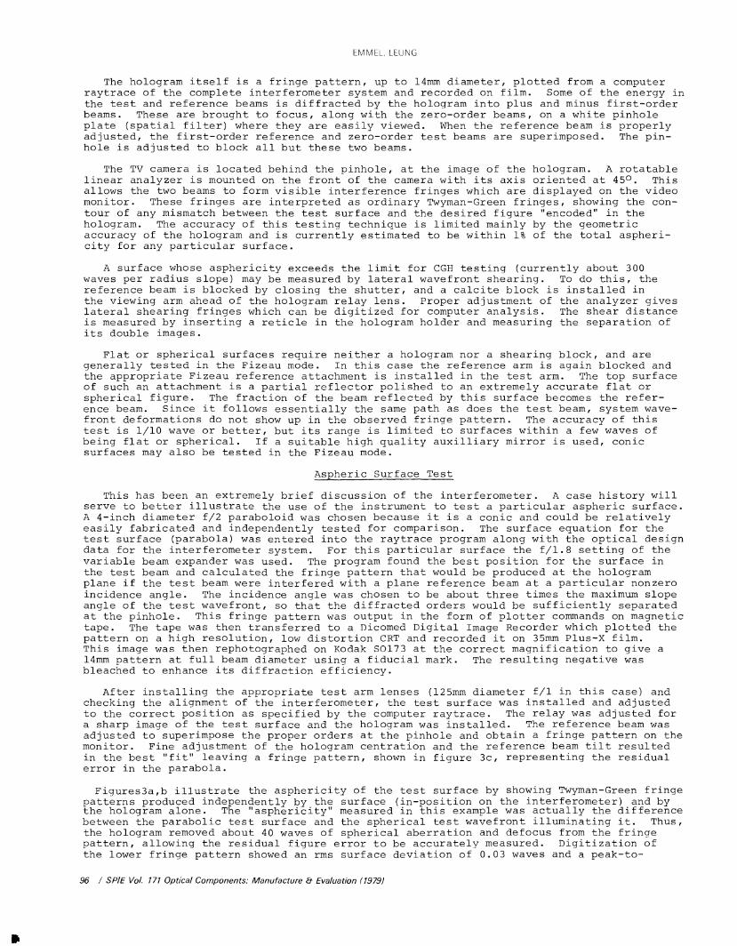
After installing the appropriate test arm lenses (125mm diameter f/1 in this case) andchecking the alignment of the interferometer, the test surface was installed and adjustedto the correct position as specified by the computer raytrace. The relay was adjusted fora sharp image of the test surface and the hologram was installed. The reference beam wasadjusted to superimpose the proper orders at the pinhole and obtain a fringe pattern on themonitor. Fine adjustment of the hologram centration and the reference beam tilt resultedin the best "fit" leaving a fringe pattern, shown in figure 3c, representing the residualerror in the parabola.
Figures3a,b illustrate the asphericity of the test surface by showing Twyman -Green fringepatterns produced independently by the surface (in- position on the interferometer) and bythe hologram alone. The " asphericity" measured in this example was actually the differencebetween the parabolic test surface and the spherical test wavefront illuminating it. Thus,the hologram removed about 40 waves of spherical aberration and defocus from the fringepattern, allowing the residual figure error to be accurately measured. Digitization ofthe lower fringe pattern showed an rms surface deviation of 0.03 waves and a peak -to-
96 / SPIE Vol. 171 Optical Components: Manufacture 8 Evaluation (1979)
EMMEL, EEUNG
The hologram itself is a fringe pattern, up to 14nun diameter, plotted from a computer raytrace of the complete interferometer system and recorded on film. Some of the energy in the test and reference beams is diffracted by the hologram into plus and minus first-order beams. These are brought to focus, along with the zero-order beams, on a white pinhole plate (spatial filter) where they are easily viewed. When the reference beam is properly adjusted, the first-order reference and zero-order test beams are superimposed. The pin- hole is adjusted to block all but these two beams.
The TV camera is located behind the pinhole, at the image of the hologram. A rotatable linear analyzer is mounted on the front of the camera with its axis oriented at 45°. This allows the two beams to form visible interference fringes which are displayed on the video monitor. These fringes are interpreted as ordinary Twyman-Green fringes, showing the con tour of any mismatch between the test surface and the desired figure "encoded" in the hologram. The accuracy of this testing technique is limited mainly by the geometric accuracy of the hologram and is currently estimated to be within 1% of the total aspheri- city for any particular surface.
A surface whose asphericity exceeds the limit for CGH testing (currently about 300 waves per radius slope) may be measured by lateral wavefront shearing. To do this, the reference beam is blocked by closing the shutter, and a calcite block is installed in the viewing arm ahead of the hologram relay lens. Proper adjustment of the analyzer gives lateral shearing fringes which can be digitized for computer analysis. The shear distance is measured by inserting a reticle in the hologram holder and measuring the separation of its double images.
Flat or spherical surfaces require neither a hologram nor a shearing block, and are generally tested in the Fizeau mode. In this case the reference arm is again blocked and the appropriate Fizeau reference attachment is installed in the test arm. The top surface of such an attachment is a partial reflector polished to an extremely accurate flat or spherical figure. The fraction of the beam reflected by this surface becomes the refer ence beam. Since it follows essentially the same path as does the test beam, system wave- front deformations do not show up in the observed fringe pattern. The accuracy of this test is 1/10 wave or better, but its range is limited to surfaces within a few waves of being flat or spherical. If a suitable high quality auxilliary mirror is used, conic surfaces may also be tested in the Fizeau mode.
Aspheric Surface Test
This has been an extremely brief discussion of the interferometer. A case history will serve to better illustrate the use of the instrument to test a particular aspheric surface. A 4-inch diameter f/2 paraboloid was chosen because it is a conic and could be relatively easily fabricated and independently tested for comparison. The surface equation for the test surface (parabola) was entered into the raytrace program along with the optical design data for the interferometer system. For this particular surface the f/1.8 setting of the variable beam expander was used. The program found the best position for the surface in the test beam and calculated the fringe pattern that would be produced at the hologram plane if the test beam were interfered with a plane reference beam at a particular nonzero incidence angle. The incidence angle was chosen to be about three times the maximum slope angle of the test wavefront, so that the diffracted orders would be sufficiently separated at the pinhole. This fringe pattern was output in the form of plotter commands on magnetic tape. The tape was then transferred to a Dicomed Digital Image Recorder which plotted the pattern on a high resolution, low distortion CRT and recorded it on 35mm Plus-X film. This image was then rephotographed on Kodak SO173 at the correct magnification to give a 14mm pattern at full beam diameter using a fiducial mark. The resulting negative was bleached to enhance its diffraction efficiency.
After installing the appropriate test arm lenses (125mm diameter f/1 in this case) and checking the alignment of the interferometer, the test surface was installed and adjusted to the correct position as specified by the computer raytrace. The relay was adjusted for a sharp image of the test surface and the hologram was installed. The reference beam was adjusted to superimpose the proper orders at the pinhole and obtain a fringe pattern on the monitor. Fine adjustment of the hologram centration and the reference beam tilt resulted in the best "fit" leaving a fringe pattern, shown in figure 3c, representing the residual error in the parabola.
Figures3a,b illustrate the asphericity of the test surface by showing Twyman-Green fringe patterns produced independently by the surface (in-position on the interferometer) and by the hologram alone. The "asphericity" measured in this example was actually the difference between the parabolic test surface and the spherical test wavefront illuminating it. Thus, the hologram removed about 40 waves of spherical aberration and defocus from the fringe pattern, allowing the residual figure error to be accurately measured. Digitization of the lower fringe pattern showed an rms surface deviation of 0.03 waves and a peak-to-
96 I SPIE Vol. 171 Optical Components: Manufacture & Evaluation (1979)
Downloaded From: http://spiedigitallibrary.org/ on 03/21/2013 Terms of Use: http://spiedl.org/terms
A NEW INSTRUMENT FOR ROUTINE OPTICAL TESTING OF GENERAL ASPHERICS
valley depth of 0.15 waves. An independent autocollimation test was made at theUniversity of Arizona using a different interferometer and a precision optical flat.The interferogram from this test is shown in figure 4. Digitization of this interfero-gram shows 0.035 waves rms and 0.17 waves peak -to- valley agreeing with the CGH resultswithin a few hundredths of a wave.
Figure 3a
4" Dia. F/2 ParabolaTwyman -Green Interferogram
Figure 3b
Wavefront Diffracted byComputer- Generated HologramTo Simulate perfect F/2Parabola and CompensateInstrumental Error
Figure 4
Autocollimation Test of F/2Parabola
Surface Deviation is:0.035 waves RMS0.171 waves P -V
Figure 3c
CGH Test of the F/2Parabola
Surface Deviation is:0.03 waves RMS (63288)0.15 waves P -V
SPIE Vol. 171 Optical Components: Manufacture 8 Evaluation (1979) / 97
A NEW INSTRUMENT FOR ROUTINE OPTICAL TESTING OF GENERAL ASPHERICS
valley depth of 0.15 waves. An independent autocollimation test was made at the University of Arizona using a different interferometer and a precision optical flat
in ° thlS tSSt 1S Sh°Wn in f±gure 4 ' Digitization of this interf^ro-a^ave!' W™ *»*-*>—— "«* agreeing with the CGH results
Figure 3a
4" Dia. F/2 Parabola Twyman-Green Interf'erogram
Figure 3b
Wavefront Diffracted by Computer-Generated HologramTo Simulate perfect F/2 Parabola and Compensate Instrumental Error
Figure 3c
CGH Test of the F/2 Parabola
Surface Deviation is: 0.03 wave s RMS (6 3 2 8&)0.15 waves P-V
Figure 4
Autocollimation Test of F/2Parabola
Surface Deviation, is:0. 035 waves RMS 0.171 waves P-V
SPiE Vol. 171 Optical Components: Manufacture & Evaluation {J979I / 97
Downloaded From: http://spiedigitallibrary.org/ on 03/21/2013 Terms of Use: http://spiedl.org/terms
EMMEL, LEUNG
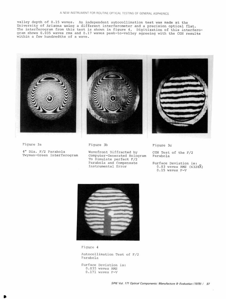
The paraboloid was also tested in the shearing mode. Interferograms were taken withthe shear in orthogonal directions, as shown in figure 5. Aberration theory predicts 39.2waves of spherical aberration for this setup. For comparison both the shearing and theTwyman -Green interferograms were measured, giving values of 39.2 and 39.0 waves respective-ly. It was the extremely fine fringe spacing that hampered the measurement of asphericTwyman -Green fringe patterns and led us to seek better ways of testing aspherics in thefirst place. In the lateral shearing technique this problem is controlled because thefringe spacing is partially a function of the shear distance, which can be varied. TheCGH technique completely eliminates the problem for aspherics up to a few hundred waves.
Figure 5a Figure 5b
Lateral Shearing Interferogram Lateral Shearing InterferogramUsing Calcite Block to test (Calcite Block Rotated 90 °)F/2 Parabola
These comparative results confirm the soundness of the techniques and the quality of theequipment. Another very important comparison is the time required to obtain results ineach of these modes. In all cases the setup and adjustment of the interferometer wasstraightforward and convenient. In terms of turnaround time from scratch for testing anew surface, the CGH mode took by far the longest because of the time required for cal-culating and making the hologram (a matter of days with the present arrangements). How-ever, once the hologram was ready, the fringe pattern was observed in a few minutes. Ifseveral of the parabolas had been available, they could all have been measured, using thesame hologram, in a time period comparable with any other production- oriented interfero-meter. In order to obtain comparable results, both the Twyman -Green (when fringes areresolvable) and shearing modes require fringe digitization and data reduction for eachsurface tested. Clearly the CGH mode is preferable for situations where several nominallyidentical surfaces are to be measured, while shearing is most practical for occasional orone of a kind surfaces.
Further Considerations
There are a few ways in which the CGH turnaround time could be drastically reduced. Atthe moment the various operations are not all in- house. Under one roof, the turnaroundtime could be less than 24 hours. Even shorter times could be realized if the hologramwere exposed directly from mag tape onto the final film (or thermoplastic). This is withinthe capability of a (hopefully) growing number of X -Y laser beam recorders.
If a quantitative analysis of the residual fringe pattern is required, there aretwo sophisticated techniques currently in use. One of them is fringe digitization, inwhich the intersections of the fringes in a particular interferogram with a set of parallel,equally spaced lines are supplied to the computer for curve fitting or other analysis.The least tedious way of getting this fringe data into the computer is to let the computerhelp by using an interactive video terminal with software that can find most of the fringesfor itself. The other analysis technique is direct phase measurement, in which the inter-ferometer is connected directly to the computer. Tropel's minicomputer -based System 70,for example, measures the equivalent of over 300 interferograms during its 6- second data
98 / SPIE Vol. 171 Optical Components: Manufacture & Evaluation (1979)
EMMEL, LEUNG
The paraboloid was also tested In the shearing mode. Interferograms were taken with the shear in orthogonal directions, as shown in figure 5. Aberration theory predicts 39.2 waves of spherical aberration for this setup. For comparison both the shearing and the Twyman-Green interferograms were measured, giving values of 39.2 and 39.0 waves respective ly. It was the extremely fine fringe spacing that hampered the measurement of aspheric Twyman-Green fringe patterns and led us to seek better ways of testing aspherics in the first place. In the lateral shearing technique this problem is controlled because the fringe spacing is partially a function of the shear distance, which can be varied. The CGH techn ique comp1e te1y e1imin a t e s the p rob1em for aspherics up to a few hundred waves.
Figure 5a Figure 5b
Lateral Shearing Interferogram Lateral Shearing InterferogramUsing Calclte Block to test (Calclte Block Rotated 90°) F/2 Parabola
These comparative results confirm the soundness of the techniques and the quality of the equipment. Another very important comparison is the time required to obtain results in each of these modes. In all cases the setup and adjustment of the interferometer was straightforward and convenient. In terms of turnaround time from scratch for testing a new surface, the CGH mode took by far the longest because of the time required for cal culating and making the hologram (a matter of days with the present arrangements). How ever, once the hologram was ready, the fringe pattern was observed In a few minutes. If several of the parabolas had been available, they could all have been measured, using the same hologram, in a time period, comparable with any other production-oriented inte.rfe.ro- me t e r. I n o r de r to ob t a in c omp a r able r e s u 11 s , bo t h t h e Twy m a n - Green (wh e n. f r i n ge s a r e resolvable) and shearing modes require fringe digitization and data reduction for each surface tested. Clearly the CGH mode is preferable for situations where several nominally identical surfaces are to be measured, while shearing Is most practical for occasional or one of a kind surfaces.
Further Considerations
There are a few ways in which the CGH turnaround time could be drastically reduced. At the moment the various operations are not all in-house. Under one roof, the turnaround time could be less than 24 hours. Even shorter times could be realized if the hologram were exposed directly from mag tape onto the final film (or thermoplastic). This is within the c a pab11i ty of a (hopefully) growIn g numbe r of X-Y laser be am re c or de rs.
If a quantitative, analysis of the residual fringe pattern Is required, there are two sophisticated techniques currently in use. One of them is fringe digitization, in which the intersections of the fringes in. a particular Interferogram with a. set of parallel, equally spaced lines are supplied to the computer for curve fitting or other analysis. The least tedious way of getting this fringe data into the computer is to let the computer help by using an interactive video terminal with software that can find most of the fringes for itself. The other analysis technique is direct phase measurement, in which the inter ferometer is connected directly to the computer. Tropel's minicomputer-based System 70, for example, measures the equivalent of over 300 interferograms during its 6-second data
98 / SP/E Vol. 171 Optical Components: Manufacture 8- Evaluation {19791
Downloaded From: http://spiedigitallibrary.org/ on 03/21/2013 Terms of Use: http://spiedl.org/terms
A NEW INSTRUMENT FOR ROUTINE OPTICAL TESTING OF GENERAL ASPHERICS
taking period and has the wavefront data (32 X 32 grid) available for analysis or redisplayin less than one minute. This gives it a very high signal to noise factor and tends toeliminate transient effects which are often "frozen" in a single interferogram.
It is not hard to visualize the interferometer, CGH recorder, and keyboard, allconnected to the computer, with access to software for ray tracing, CGH calculation andwavefront analysis. When one considers the eauipment that is now being developed forfabricating precision aspherics, a surface measurement system like this is clearly anessential, independent measurement tool compatible with the machine control systems inboth accuracy and data format.
Acknowledgement
The authors wish to acknowledge the valuable personal assistance of Dr. James C. Wyant,at the University of Arizona's Optical Sciences Center. His work in the field of asphericsurface testing formed the basis for the design of the instrument we describe.
References
1. Polster, H. D., et al, "New Developments in Interferometry", Applied Optics, Vol. 8,pp. 521 -556. 1969.
2. Wyant, J. C., "Testing Aspherics Using Two- Wavelength Holography ", Applied Optics,Vol. 10, pp. 2113 -2118. 1971.
3. MacGovern A. J., and J. C. Wyant, "Computer Generated Holograms for TestingOptical Elements ", Applied Optics, Vol. 10, pp. 619 -624. 1971.
4. Rimmer, M. P., and J. C. Wyant, "Evaluation of Large Aberration Using a Lateral -Shear Interferometer Having Variable Shear ", Applied Optics, Vol. 14, pp. 142 -150. 1975.
SPIE Vol. 171 Optical Components: Manufacture & Evaluation (1979) / 99
A NEW INSTRUMENT FOR ROUTINE OPTICAL TESTING OF GENERAL ASPHERICS
taking period and has the wavefront data (32 X 32 grid) available for analysis or redisplay in less than one minute. This gives it a very high signal to noise factor and tends to eliminate transient effects which are often "frozen" in a single interferogram.
It is not hard to visualize the interferometer, CGH recorder, and keyboard, all connected to the computer, with access to software for ray tracing, CGH calculation and wavefront analysis. When one considers the eauipment that is now being developed for fabricating precision aspherics, a surface measurement system like this is clearly an essential, independent measurement tool compatible with the machine control systems in both accuracy and data format.
Acknowledgement
The authors wish to acknowledge the valuable personal assistance of Dr. James C. Wyant, at the University of Arizona's Optical Sciences Center. His work in the field of aspheric surface testing formed the basis for the design of the instrument we describe.
References
1. Polster, H. D., et al, "New Developments in Interferometry", Applied Optics, Vol. 8, pp. 521-556. 1969.
2. Wyant, J. C., "Testing" Aspherics Using Two-Wavelength Holography", Applied Optics, Vol. 10, pp. 2113-2118. 1971.
3. MacGovern A. J., and J. C. Wyant, "Computer Generated Holograms for Testing Optical Elements", Applied Optics, Vol. 10, pp. 619-624. 1971.
4. Rimmer, M. P., and J. C. Wyant, "Evaluation of Large Aberration Using a Lateral- Shear Interferometer Having Variable Shear", Applied Optics, Vol. 14, pp. 142-150. 1975.
SPIE Vol. 171 Optical Components: Manufacture 8- Evaluation (1979) I 99
Downloaded From: http://spiedigitallibrary.org/ on 03/21/2013 Terms of Use: http://spiedl.org/terms