Embed Size (px)
Citation preview
The Japanese Geotechnical Society
Soils and Foundations
Soils and Foundations 2013;53(3):462–468
0038-0http://d
nCorE-m
bcwangbckclam
1Tel.2Tel.3Tel.Peer
806 & 201x.doi.org/1
respondingail [email protected]@cityu.e: +1 780: +852 27: +852 28review un
ciencedirect.comwww.elsevier.com/locate/sandf
www.sjournal homepage:
A new laboratory apparatus for studying dynamic compaction groutinginto granular soils
S.Y. Wanga,n, D.H. Chanb,1, K.C. Lamc,2, S.K.A. Aud,3
aARC Centre of Excellence for Geotechnical Science and Engineering, Department of Civil, Surveying and EnvironmentalEngineering, The University of Newcastle Callaghan, NSW 2308, Australia
bDepartment of Civil and Environmental Engineering, University of Alberta, Canada T6G 2W2cDepartment of Building and Construction, City University of Hong Kong, Tat Chee Avenue, Kowloon, Hong Kong
dDepartment of Civil Engineering, The University of Hong Kong, Pokfulam Road, Hong Kong
Received 25 May 2010; received in revised form 25 June 2012; accepted 15 July 2012Available online 2 May 2013
Abstract
As granular soils may be compressible or have inadequate strength, compaction is particularly useful when soils are subjected to dynamic loading orcyclic loading. A new laboratory apparatus for investigating dynamic compaction has been designed and fabricated. The basic principle of this newtechnique is to introduce vibrations during the expansion process in static compaction grouting. In these tests, the injection pressure, the excess pore waterpressure, and the change in void ratio of the specimens are measured. The main focus is to investigate the development of the injection pressure, the voidratio, and the excess pore water pressure due to dynamic compaction and the subsequent consolidation of the soils. In addition, the relative density of thesoils is used to evaluate the dynamic compaction efficiency. Scaled laboratory experiments are conducted to study the effect of this dynamic compactionfrequency on compaction efficiency. The experimental results show that the change in void ratio in the dynamic compaction tests is about four times greaterthan that in the static compaction tests. Dynamic compaction frequency plays an important role in soil densification due to dynamic compaction.& 2013 The Japanese Geotechnical Society. Production and hosting by Elsevier B.V. All rights reserved.
Keywords: Dynamic compaction; Frequency; Soil densification; Compaction efficiency
1. Introduction
During the past decades, with the development of buildingconstruction and geotechnical engineering, soil improvement by
3 The Japanese Geotechnical Society. Production and hosting by0.1016/j.sandf.2013.04.007
author. Tel.: +61 2 4921 5745; fax: +61 2 4921 6991.sses: [email protected],om (S.Y. Wang), [email protected] (D.H. Chan),du.hk (K.C. Lam), [email protected] (S.K.A. Au).492 4725; fax: +1 780 492 0249/+1 780 492 8198.88 7238; fax: +852 2788 7238.57 8552; fax: +852 2559 5337.der responsibility of The Japanese Geotechnical Society.
densification has shown much growth in the world, and more andmore poor or unstable soils are encountered in many projects.If granular soils are compressible or have inadequate strength,compaction is particularly useful when soils are subjected todynamic loading or cyclic loading. Both dynamic compactionand vibro-compaction are capable of achieving significant densi-fication of loose granular deposits (Greenwood and Kirsch, 1984).The effects of vibrations on granular soils are changes in densityand in the state of the pore pressure in the material. The use of thevibratory method, therefore, is an effective means of compactingsoils (Mitchell and Jardine, 2002).Compaction grouting is a traditional technology for soil
improvement; it is performed by injecting highly viscous groutunder high pressure to compact a compressible soil (Graf, 1969;Warner and Brown, 1974). Many researchers have created physical
Elsevier B.V. All rights reserved.
Data Log System
Personal computer
Air Compressor
1
23
4
67
7
8
Pressure/volumeController
Pressure Pulse Device
9
10
Cast Iron Weights
Loading Frame
GDS controller
Specimen device Pressure Pulsing
Device
Personal Computer
Specimen device
Volume Gauge
Carbon dioxide supplier
De-Air Water Supply Device
5
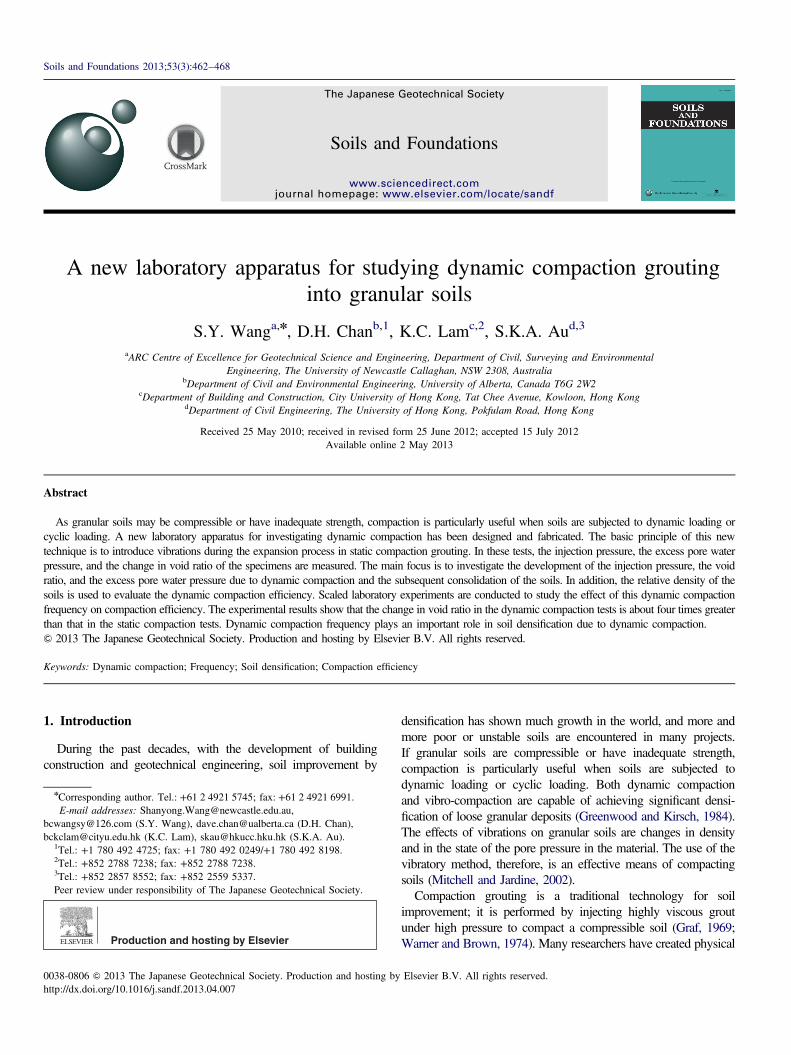
Fig. 2. (a) Schematic layout of dynamic compaction grouting experimentaltests. (b) Part of the laboratory tests setup. Notes: 1: Confining pressuretransducer, 2: Pore water pressure transducer, 3: Injection pressure transdu-cer, 4: Back pressure transducer, 5: Balloon, 6: Soil specimen, 7: Porousstone, 8: O ring, 9: Tap, 10: LVDT.
S.Y. Wang et al. / Soils and Foundations 53 (2013) 462–468 463
models to study the mechanism of compaction grouting. Forinstance, Younis (1994) conducted laboratory compaction groutingtests to study grout bulb development and soil densification; Au(2001) and Soga et al. (2004) used modified consolidometers toinvestigate compaction efficiency by measuring the deformation ofclay specimens under axi-symmetrical conditions. Wang et al.(2010) designed and fabricated a new laboratory apparatus toinvestigate the behavior of compaction grouting under triaxialconditions. Using this laboratory apparatus, the injection pressure,the void ratio, and the excess pore water pressure were measuredduring the process of compaction grouting and the subsequentconsolidation of the soils. However, all of these laboratory testswere limited to static compaction grouting. Since granular soil ismost effectively compacted using vibrations, vibrations are intro-duced in the compaction grouting in the current laboratory tests.
The basic concept of dynamic compaction grouting is shownin Fig. 1. The new technique introduces vibrations to themembrane of the grouting bag during the expansion/compactionprocess (Fig. 1(b)). Unlike static compaction grouting (Fig. 1(a)), it is not only the membrane due to internal pressure that cancompact the surrounding soils, but the vibrations of themembrane generate waves in the soil, moving the surroundingsoil particles, which in turn results in a denser material. Thecurrent investigation focuses on the laboratory study of dynamiccompaction grouting in completely decomposed granite soils ofHong Kong. The design, the fabrication, and the assembly of thenew laboratory apparatus are presented to investigate thefundamental behavior of dynamic compaction grouting. Bothstatic and dynamic compaction tests are conducted to comparethese two methods in the densification of granular soils.In addition, the effect of the dynamic compaction frequencyon compaction efficiency is examined by experimental tests.
2. Experimental setup and procedures
2.1. Schematic of experimental setup
Fig. 2(a) shows the schematics of the experimental setup for thedynamic compaction grouting tests. The setup consists of astandard triaxial cell with an electronic data logger connected toa computer to record and control the cell pressure, the back
Injection of grout under high pressure
Loose Soil
Soil is densified by expansion of cavity
Injection of grout with pressure pulse
Loose Soil
Soil is densified by waves and vibration
Membrane of injection needle
Membrane of injection needle
Fig. 1. Schematic static compaction and dynamic compaction.
pressure, the injection pressure, and the change in volume of thespecimens. An injection needle is placed in the middle of eachspecimen, 75 mm in diameter and 150 mm in height. This injectionneedle is firstly placed in the center of the base plate of the
Injection Needle
Cell Pressure Transducer
Pore Pressure Transducer
Back Pressure TransducerInjection Pressure
O ring
Transducer
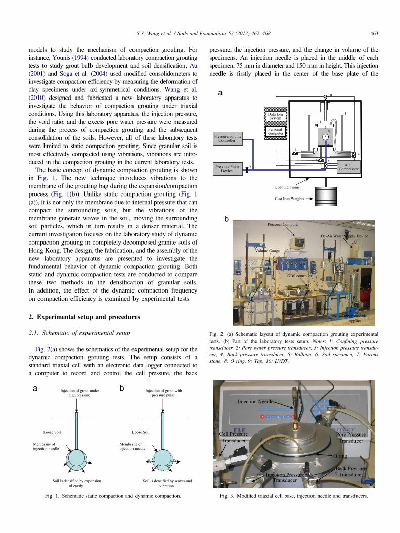
Fig. 3. Modified triaxial cell base, injection needle and transducers.
S.Y. Wang et al. / Soils and Foundations 53 (2013) 462–468464
modified triaxial apparatus (Fig. 3). Each soil specimen is thenprepared in a split mold, in twelve layers, using the moist tampingmethod (Ladd, 1978; Wang et al., 2010). The tip of the needle iscovered by an expandable latex membrane. The injection pressureis measured by transducer 3 in Fig. 2(a). A Geotechnical DigitalSystems (GDS) controller is used to control the injection rate andthe volume of the water injected into the needle. A pressure pulsingdevice is connected to the injection tube to generate pressurepulses. On the other hand, a motor is connected to the pressurepulsing device to control the frequency of the pressure pulses.Fig. 2(b) shows a photograph of the laboratory test setup. Twospecimens can be tested at the same time.
In preparation of the dynamic compaction grouting tests, thesoil is compacted in the triaxial apparatus to obtain the desiredinitial relative density, the same as in the static compactiongrouting tests (Wang et al., 2010). The confining pressure andthe pore water pressure are measured by transducers 1 and 2,respectively (Fig. 2(a)). Water can be injected into the injectionneedle to compact and expand the membrane into a balloon atthe top of the injection needle. The injection pressure ismeasured using transducer 3. Pressure pulses are generatedby a pulsing device connected to the injection tube. Thevibrations of the membrane generate waves which are trans-ferred to the soil and move the surrounding soil particles into adenser state. With the consolidation of the soil, the volume ofthe drained water is measured using transducer 4. As fortransducer 4, it performs two functions: one is to control theback pressure during the saturation of the soils and the other isto use this channel to measure the change in volume during thedrained tests when the back pressure transducer is turned off. Itis noted that the confining (cell) pressure and the back pressurein the tests were 250 kPa and 50 kPa, respectively. Fig. 3shows the four transducers and the injection needle setup.
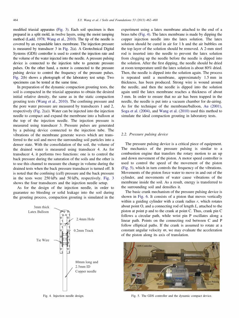
As for the design of the injection needle, in order toguarantee no bleeding or solid leakage into the soil duringthe grouting process, compaction grouting is simulated in the
2.4mm Hole
0.2mm Track
80mm long and 2.5mm ID Copper needle
Tie Wire
3mm thick Latex Balloon
Fig. 4. Injection needle design.
experiment using a latex membrane attached to the end of abrass tube (Fig. 4). The latex membrane is made by dipping thecopper injection needle into the latex solution. The latexsolution should be cured in air for 1 h and the air bubbles onthe top layer of the solution should be removed. A 2-mm steelrod is inserted into the needle to prevent the latex solutionfrom clogging up the needle before the needle is dipped intothe solution. After the first dipping, the needle should be driedat room temperature until the latex solution is about 80% dried.Then, the needle is dipped into the solution again. The processis repeated until a membrane, approximately 1.5 mm inthickness, has been produced. Strong wire is wound aroundthe needle, and then the needle is dipped into the solutionagain until the latex membrane reaches a thickness of about3 mm. In order to ensure that no air has been trapped in theneedle, the needle is put into a vacuum chamber for de-airing.As for the technique of the membrane/balloon, Au (2001),Soga et al. (2004), and Wang et al. (2010) used this method tosimulate the ideal compaction grouting in laboratory tests.
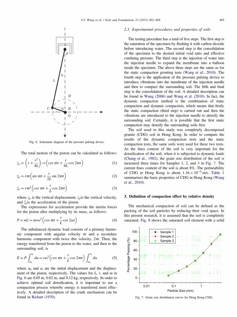
2.2. Pressure pulsing device
The pressure pulsing device is a critical piece of equipment.The mechanics of the pressure pulsing is similar to acombustion engine that transfers the rotary motion to an upand down movement of the piston. A motor speed controller isused to control the speed of the movement of the piston(Fig. 5), which in turn controls the frequency of the vibrations.Movements of the piston force water to move in and out of thecylinder, and movements of water cause vibrations of themembrane inside the soil. As a result, energy is transferred tothe surrounding soil and densifies it.The basic crank mechanism of the pressure pulsing device is
shown in Fig. 6. It consists of a piston that moves verticallywithin a guiding cylinder with a crank radius r, which rotatesabout point O, and a connecting rod of length L, attached to thepiston at point p and to the crank at point C. Thus, crank pin Cfollows a circular path, while wrist pin P oscillates along alinear path. Points on the connecting rod between C and Pfollow elliptical paths. If the crank is assumed to rotate at aconstant angular velocity ϖ, we may evaluate the accelerationof the piston along its axis of translation.
GDS Controller
Pressure Pulsing Device Motor
Motor Speed Controller
Fig. 5. The GDS controller and the dynamic compact device.
φ
P
D
B
O
C
L
r ω
Fig. 6. Schematic diagram of the pressure pulsing device.
10.10.01
0
20
40
60
80
100 Sample 1 Sample 2 Sample 3
Perc
enta
ge P
assi
ng (%
)
Particle Size (mm)
Fig. 7. Grain size distribution curves for Hong Kong CDG.
S.Y. Wang et al. / Soils and Foundations 53 (2013) 462–468 465
The total motion of the piston can be calculated as follows:
zp ¼ r þ r2
4L
� �−r cos ϖt þ r
4Lcos 2ϖt
� �ð1Þ
zp ¼ rϖ sin ϖt þ r
2Lsin 2ϖt
� �ð2Þ
€zp ¼ rϖ2 cos ϖt þ r
Lcos 2ϖt
� �ð3Þ
where zp is the vertical displacement, zpis the vertical velocity,and €zpis the acceleration of the piston.
The expressions for acceleration provide the inertia forcesfor the piston after multiplying by its mass, as follows:
P¼m€z¼mrω2 cos ϖt þ r
Lcos 2ωt
� �ð4Þ
The unbalanced dynamic load consists of a primary harmo-nic component with angular velocity ϖ and a secondaryharmonic component with twice this velocity, 2ϖ. Then, theenergy transferred from the piston to the water, and then to thesurrounding soil, is
E¼ P
Z ut
u0
du¼ rω2 cos ϖt þ r
Lcos 2ϖt
� �Z ut
u0
du ð5Þ
where u0 and ut are the initial displacement and the displace-ment of the piston, respectively. The values for L, r, and m inFig. 6 are 0.05 m, 0.02 m, and 0.12 kg, respectively. In order toachieve optimal soil densification, it is important to use acompaction process whereby energy is transferred most effec-tively. A detailed description of the crank mechanism can befound in Richart (1970).
2.3. Experimental procedures and properties of soils
The testing procedure has a total of five steps. The first step isthe saturation of the specimen by flushing it with carbon dioxidebefore introducing water. The second step is the consolidationof the specimen to the desired initial void ratio and effectiveconfining pressure. The third step is the injection of water intothe injection needle to expand the membrane into a ballooninside the specimen. The above three steps are the same as forthe static compaction grouting tests (Wang et al., 2010). Thefourth step is the application of the pressure pulsing device tointroduce vibrations into the membrane of the injection needleand then to compact the surrounding soil. The fifth and finalstep is the consolidation of the soil. A detailed description canbe found in Wang (2006) and Wang et al. (2010). In fact, thedynamic compaction method is the combination of staticcompaction and dynamic compaction, which means that firstlythe static compaction (third step) is carried out and then thevibrations are introduced to the injection needle to densify thesurrounding soil. Certainly, it is possible that the first staticcompaction may densify the surrounding soils first.The soil used in this study was completely decomposed
granite (CDG) soil in Hong Kong. In order to compare theresults of the dynamic compaction tests and the staticcompaction tests, the same soils were used for these two tests.As the fines content of the soil is very important for thedensification of the soil, when it is subjected to dynamic loads(Chang et al., 1982), the grain size distribution of the soil ismeasured three times for Samples 1, 2, and 3 in Fig. 7. Thecurrent fines content of the soil is about 8%. The permeabilityof CDG in Hong Kong is about 1.16� 10−6 m/s. Table 1summarizes the basic properties of CDG in Hong Kong (Wanget al., 2010).
3. Definition of compaction effect by relative density
The mechanical compaction of soil can be defined as thepacking of the soil particles by reducing their void space. Inthis present research, it is assumed that the soil is completelysaturated. Fig. 8 shows the saturated soil element with a solid
S.Y. Wang et al. / Soils and Foundations 53 (2013) 462–468466
volume of 1. From the definition of void ratio (e),
e¼ Vw
Vsð6Þ
where Vw is the volume of water in the voids and Vs is thevolume of soil solids. If Vs is equal to 1, then
e¼ Vw
Vs¼ Vw
1¼ Vw ð7Þ
Since the soil is completely saturated, the change in voidratio of the soil should be equal to the change in volume of thewater; thus,
Δe¼ΔVw ð8Þ
Hence
e¼ e0−Δe¼ e0−ΔVw ð9Þ
In the present dynamic compaction grouting tests, in orderto avoid the difference in initial void ratio for each test, the
Table 1Physical properties of Hong Kong CDG (Wang et al., 2010).
Properties Value
Natural water content 8%Gravel 30%Sand 64%Fine particles 6%D10 0.18 mmD30 0.7 mmD60 1.8 mmCoefficient of uniformity (D60/D10) 10Liquid limit 36%Plastic limit 25%Plasticity index 11%Maximum dry density 1820 kg/m3
Optimum moisture content 11%emax 1.096emin 0.493
Δ VW
Vw
VS =1
V0
Δ VW
Water
Solid
Volume
Fig. 8. Saturated soil element and volume gauge to measure volume change ofsoils. (a) Saturated soil element with solid volume =1 and (b)Volume Gauge.
normalized void ratio is given from Eq. (9), namely,
e=e0 ¼ 1−ΔVw=e0 ð10ÞFor each test, the initial void ratio of the soil can be measured
before the test, and the change in volume of the water can bemeasured using a volume gauge (Fig. 8(b)) during the test.In addition, the term relative density is commonly used to
indicate the denseness of a granular soil. In the present study,the relative density of soil is selected for determining thecompaction efficiency after dynamic compaction grouting. Therelative density is defined as
Dr ¼emax−e
emax−eminð11Þ
where Dr is the relative density, emax is the void ratio of thesoil in the loosest condition, and emin is the void ratio of thesoil in the densest condition. Since the maximum void ratio(emax) and the minimum void ratio (emin) can be measuredbeforehand, as shown in Table 1, the relative density (compac-tion efficiency) of the soil, due to dynamic compaction, can bedetermined by calculating the void ratio (e) based on Eq. (9).In addition, based on Eqs. (9) and (11), the relationshipbetween void ratio change (Δe) and Dr is
Dr ¼emax−e0 þ Δeemax−emin
¼ emax−e0emax−emin
þ Δeemax−emin
ð12Þ
In fact, section Δe/(emax−emin) has been defined as compac-tion efficiency in Wang et al. (2010).
4. Experimental results
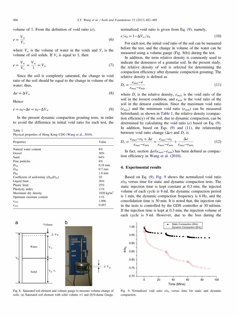
Based on Eq. (9), Fig. 9 shows the normalized void ratioe/e0 versus time for static and dynamic compaction tests. Thestatic injection time is kept constant at 0.3 min, the injectedvolume of each cycle is 8 ml, the dynamic compaction periodis 1 min, the dynamic compaction frequency is 6 Hz, and theconsolidation time is 30 min. It is noted that, the injection ratein the tests is controlled by the GDS controller at 30 ml/min.If the injection time is kept at 0.3 min, the injection volume ofeach cycle is 9 ml. However, due to the loss during the
0 20 40 60 80 1000.70
0.75
0.80
0.85
0.90
0.95
1.00 Static Compaction (0Hz) Dynamic Compaction (6Hz)
e/e 0
Time (Mins)
Fig. 9. Normalized void ratio e/e0 versus time for static and dynamiccompaction.
0 20 40 60 80 100
60
80
100
120
140
160
180
200
220
240
260
Por
e W
ater
Pre
ssur
e (k
Pa)
Time (Mins)
Static Compaction (0Hz) Dynamic Compaction (6Hz)
Fig. 11. Pore water pressures versus time for static and dynamic compaction.
S.Y. Wang et al. / Soils and Foundations 53 (2013) 462–468 467
grouting process, the injection volume in the injection needleafter the calibration is about 8 ml.
From Fig. 9, it is clear that the change in void ratio for eachcycle is much larger than that in static compaction. Granular soilsare more effectively densified by cyclic loading than by staticloading. In fact, dynamic compaction tests combine both static anddynamic compaction. Not only can the membrane density thesurrounding soil, due to internal pressure (static compaction), butthe vibrations of the membrane generate waves in the soil andmove the surrounding soil particles into a denser state. Accord-ingly, under the combined effect of static and dynamic compac-tion, the change in void ratio for dynamic compaction tests ismuch larger than that for solely static compaction tests. Forinstance, the change in total normalized void ratio for the staticcompaction tests is 0.0644, while the change in total normalizedvoid ratio for the dynamic compaction tests is 0.2554, which isabout four times that of the static compaction tests.
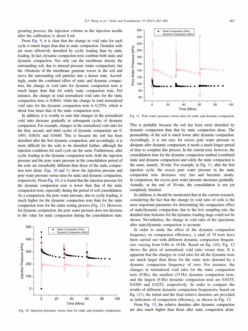
In addition, it is worthy to note that changes in the normalizedvoid ratio decrease gradually in subsequent cycles of dynamiccompaction. For example, changes in the normalized void ratio forthe first, second, and third cycles of dynamic compaction are 0.1493, 0.0610, and 0.0440. This is because the soil has beendensified after the first dynamic compaction, and accordingly, it ismore difficult for the soils to be densified further, although theinjection conditions for each cycle are the same. Furthermore, aftercyclic loading in the dynamic compaction tests, both the injectionpressure and the pore water pressure in the consolidation period ofthe soils are remarkably different than those of the static compac-tion tests alone. Figs. 10 and 11 show the injection pressure andpore water pressure versus time for static and dynamic compaction,respectively. From Fig. 10, it is found that the injection pressure forthe dynamic compaction tests is lower than that of the staticcompaction tests, especially during the period of soil consolidation.As a comparison, the pore water pressure, due to cyclic loading, ismuch higher for the dynamic compaction tests than for the staticcompaction tests for the entire testing process (Fig. 11). However,for dynamic compaction, the pore water pressure does not decreaseto the value for static compaction during the consolidation state.
0 20 40 60 80 100
0
100
200
300
400
500
Inje
ctio
n P
ress
ure
(kP
a)
Time (Mins)
Static Compaction (0Hz) Dynamic Compaction (6Hz)
Fig. 10. Injection pressures versus time for static and dynamic compaction.
This is probably because the soil has been more densified bydynamic compaction than that by static compaction alone. Thepermeability of the soil is much lower after dynamic compaction.Accordingly, it is not easy for excess pore water pressure todissipate after dynamic compaction; it needs a much longer periodof time to complete this process. In the current tests, however, theconsolidation time for the dynamic compaction method (combinedstatic and dynamic compaction) and solely the static compaction isthe same, namely, 30 min. For example, in Fig. 11, after the firstinjection cycle, the excess pore water pressure in the staticcompaction tests decreases very fast and becomes steady.In comparison, the excess pore water pressure decreases gradually.Actually, at the end of 30 min, the consolidation is not yetcompletely finished.In addition, it should be mentioned that in the current research,
considering the fact that the change in void ratio of soils is themost important parameter for determining the compaction effectof static/dynamic compaction, due to the low sampling rate, thedetailed time histories for the dynamic loading stage could not beshown. Nevertheless, the change in void ratio of the specimensafter static/dynamic compaction is accurate.In order to study the effect of the dynamic compaction
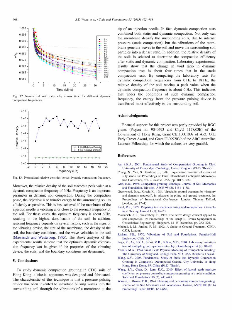
frequency on compaction efficiency, a total of 19 tests havebeen carried out with different dynamic compaction frequen-cies varying from 0 Hz to 18 Hz. Based on Eq. (10), Fig. 12shows the plots of normalized void ratio versus time. It isapparent that the changes in void ratio for all the dynamic testsare much larger than those for the static tests denoted by adynamic compaction frequency of zero. For instance, thechanges in normalized void ratio for the static compactiontests (0 Hz), the smallest (15 Hz) dynamic compaction tests,and the largest (6 Hz) dynamic compaction tests are 0.0155,0.0389 and 0.0252, respectively. In order to compare theresults of different dynamic compaction frequencies, based onEq. (11), the initial and the final relative densities are providedas indicators of compaction efficiency, as shown in Fig. 13.From Fig. 13, the relative densities after dynamic compaction
are also much higher than those after static compaction alone.
0 5 10 15 20 25 30
0.960
0.965
0.970
0.975
0.980
0.985
0.990
0.995
1.000
1Hz 2Hz 3Hz 4Hz 5Hz 6Hz 7Hz 8Hz 9Hz 10Hz 11Hz 12Hz 13Hz 14Hz 15Hz 16Hz 17Hz 18Hz 0 Hz
e/e 0
Time (Mins)
Fig. 12. Normalized void ratio e/e0 versus time for different dynamiccompaction frequencies.
-2 0 2 4 6 8 10 12 14 16 18 200.40
0.41
0.42
0.43
0.44
0.45
0.46
0.47
Initial Relative Density Final Relative Density
Rel
ativ
e D
ensi
ty
Frequency (Hz)
Fig. 13. Normalized relative densities versus dynamic compaction frequency.
S.Y. Wang et al. / Soils and Foundations 53 (2013) 462–468468
Moreover, the relative density of the soil reaches a peak value at adynamic compaction frequency of 6 Hz. Frequency is an importantparameter in dynamic soil compaction. During the compactionphase, the objective is to transfer energy to the surrounding soil asefficiently as possible. This is best achieved if the membrane of theinjection needle is vibrating at or close to the resonant frequency ofthe soil. For these cases, the optimum frequency is about 6 Hz,resulting in the highest densification of the soil. In addition,resonant frequency depends on several factors, such as the mass ofthe vibrating device, the size of the membrane, the density of thesoil, the boundary conditions, and the wave velocities in the soil(Massarsch and Westerberg, 1995). The above analyses of theexperimental results indicate that the optimum dynamic compac-tion frequency can be given if the properties of the vibratingdevice, the soils, and the boundary conditions are determined.
5. Conclusions
To study dynamic compaction grouting in CDG soils ofHong Kong, a triaxial apparatus was designed and fabricated.The characteristic of this technique is that a pressure pulsingdevice has been invented to introduce pulsing waves into thesurrounding soil through the vibrations of a membrane at the
tip of an injection needle. In fact, dynamic compaction testscombined both static and dynamic compaction. Not only canthe membrane densify the surrounding soils, due to internalpressure (static compaction), but the vibrations of the mem-brane generate waves to the soil and move the surrounding soilparticles into a denser state. In addition, the relative density ofthe soils is selected to determine the compaction efficiencyafter static and dynamic compaction. Laboratory experimentalresults show that the change in void ratio in dynamiccompaction tests is about four times that in the staticcompaction tests. By comparing the laboratory tests fordynamic compaction frequencies from 0 Hz to 18 Hz, therelative density of the soil reaches a peak value when thedynamic compaction frequency is about 6 Hz. This indicatesthat under the conditions of such dynamic compactionfrequency, the energy from the pressure pulsing device istransferred most effectively to the surrounding soil.
Acknowledgments
Financial support for this project was partly provided by RGCgrants (Project no. 9040593 and CityU 1178/03E) of theGovernment of Hong Kong, Grant CE110001009 of ARC CoEEarly Career Award, and Grant FL0992039 of the ARC AustralianLaureate Fellowship, for which the authors are very grateful.
References
Au, S.K.A., 2001. Fundamental Study of Compensation Grouting in Clay.University of Cambridge, Cambridge, United Kingdom (Ph.D. Thesis).
Chang, N., Yeh, S., Kaufman L., 1982. Liquefaction potential of clean andsilty sands. In: Proceedings of Third International Earthquake Microzona-tion Conference, vol. 2. Seattle, USA, pp. 1017–1032.
Graf, E.D., 1969. Compaction grouting technique. Journal of Soil Mechanicsand Foundation, Division, ASCE 95 (5), 1151–1158.
Greenwood, D.A., Kirsch, K., 1984. “Specialist ground treatment by vibratoryand dynamic methods”, in advances in piling and ground treatment. In:Proceedings of International Conference. London Thomas Telford,London, pp. 17–45.
Ladd, R.S., 1978. Preparing test specimens using undercompaction. Geotech-nical Testing Journal 1 (1), 16–23.
Massarsch, K.R., Westerberg, E., 1995. The active design concept applied tosoil compaction. In: Proceedings of the Bengt B. Broms Symposium inGeotechnical Engineering. Singapore, 13–15 December, pp. 262–276.
Mitchell, J. M., Jardine, F. M., 2002. A Guide to Ground Treatment. CIRIAC573, London.
Richart, F.E., 1970. Vibrations of Soil and Foundations. Prentice-HallEnglewood Cliffs, NJ.
Soga, K., Au, S.K.A., Jafari, M.R., Bolton, M.D., 2004. Laboratory investiga-tion of multiple grout injections into clay. Geotechnique 54 (2), 81–90.
Younis, M.A., 1994. Small Scale Physical Modeling of Compaction Grouting.The University of Maryland, College Park, MD, USA (Master’s Thesis).
Wang, S.Y., 2006. Fundamental Study of Static and Dynamic CompactionGrouting in Completely Decomposed Granite. City University of HongKong, Hong Kong, PR China (Ph.D. Thesis).
Wang, S.Y., Chan, D., Lam, K.C., 2010. Effect of lateral earth pressurecoefficient on pressure controlled compaction grouting in triaxial condition.Soils and Foundations 50 (3), 441–445.
Warner, J., Brown, D.R., 1974. Planning and performing compaction grouting.Journal of the Soil Mechanics and Foundations Division, ASCE 100 (GT6)Proceedings Paper 10606, 653–666.