Embed Size (px)
Citation preview

A new method for preventing air-source heat pumps and
refrigerators from frosting
Li Zhang*, Takeshi Fujinawa, Katsumi Hashimoto, Michiyuki Saikawa
Central Research Institute of Electric Power Industry, 2-6-1 Nagasaka, Yokosuka City, Kanagawa Prefecture, 240-0196, JAPAN
Abstract
In this study, we proposed a new method to prevent air-source heat pumps and refrigerators from frosting, in which a desiccant-coated heat exchanger (DCHE) is used to dehumidify the air before it enters the evaporator, consequently retarding frosting on its surface. Theoretical and experimental studies were conducted for the proposed frost-free heat pump and frost-free household refrigerator-freezer. Simulation results show that the proposed systems have high energy efficiency, while experimental results verify that frost-free operation could be realized and the DCHE could be regenerated under the condensation temperature of the proposed systems. © 2017 Stichting HPC 2017.
Selection and/or peer-review under responsibility of the organizers of the 12th IEA Heat Pump Conference 2017.
Keywords: heat pump, refrigerator, frost, desiccant, dehumidification;
1. Introduction
Air-source heat pumps (ASHPs) are a promising technology, which is widely applied as an economic form of
heating. However, one of the largest problems encountered is evaporator frosting and the subsequent need to
defrost at a low ambient temperature and high relative humidity. Frost normally accumulates when the air
temperature is -7 to 5.5ºC and the relative humidity exceeds 60%; a frequent atmospheric combination [1]. In
fact, frosting commonly occurs when the air temperature is lower than -7ºC. The frosting-defrosting process
causes significant problems, such as reduced energy efficiency and heating shutdown, which underlines the need
to prevent or delay the frosting process when designing an air-source heat pump. Generally, defrosting can be
achieved by supplying heat to the heat exchanger by various methods: electric resistance heater defrosting,
warm-air defrosting [1], reverse cycle defrosting cycle [2-3] and hot-gas bypass cycle defrosting [4-7].
Defrosting using an electric resistance heater or warm air is not commonly employed in heat pump operations
because heating from electrical resistive heaters is expensive. Reverse cycle defrosting is accomplished by
reversing the normal heating mode. As for the hot-gas bypass defrosting method, the superheated refrigerant
from the compressor flows directly to the evaporator; bypassing the condenser and expansive device and this
approach is considered one of the most effective means of defrosting. However these defrosting methods result
in heating shutdown and decrease system efficiency. Another disadvantage is that some melted water remains on
the heat-exchanger surfaces. As the defrost cycle ends and the heat pump switches to heating mode, this water
freezes to form a high-density frost, which is slow to melt during subsequent defrosts [1].
Furthermore, frost formation is a common phenomenon observed in refrigerators, including household
refrigerator-freezers, refrigerated display cabinets, refrigerated warehouses and so on. The accumulation of frost
on the evaporator surface of refrigerators increases thermal resistance and the air side pressure drops, resulting in
higher electrical power input to the compressor and decreased refrigerating capacity. Modern refrigerators
* Corresponding author. Tel.: +81-4-6856-2121; fax: +81-4-6856-3346.
E-mail address: [email protected].

Li Zhang/ 12th IEA Heat Pump Conference (2017) O.1.6.3
2
generally have an automatic mechanism to remove frost using an electrical resistance heater before their
performance declines significantly. Although some energy-saving efforts have been made in the defrosting
process of refrigerators, the process still requires a significant amount of energy. The efficiency of a defrost
heater, defined as the ratio of total energy input to the energy required to melt the frost, was measured at 15 ~
30% [8-9] in a household refrigerator-freezer, while the electrical power consumption of the refrigerator-freezer
was found to increase by about 18% due to the automatic defrosting [8][10]. Bahman et al. reported that,
depending on store size, humidity in store and the cabinet types, the energy associated with defrosting
refrigerated display cabinets may exceed 15% of the total refrigeration electrical energy in a supermarket [11].
Furthermore, during defrosting, the compressor and fan remain off and part of the heat provided by the electrical
heater is transferred to the refrigerated compartments. It was observed that the air temperature of the cabinet
during the defrosting process rose from -1.57 to 6.8ºC for the refrigerator compartment (R. Compartment) and -
23.1 to -11.8ºC for the freezer compartment (F. Compartment) [12] in a household refrigerator-freezer. This
temperature fluctuation affects food quality and the compressor also has to run for longer to compensate for this
extra thermal load after the defrosting process. The defrosted water runs through a tube and is collected in a tray,
which is often located close to the compressor or condenser and finally evaporates from the tray due to the heat
of the compressor or condenser. This system works satisfactorily in countries where the ambient air has low
relative humidity and the amount of defrosted water is also low. However, under hot and humid ambient
conditions, more defrosted water is generated, but the evaporation speed is slower, which may lead to water
overflowing from the tray [13].
In our study, we focused on developing frost-free air-source heat pump and refrigeration systems, in which a
desiccant is applied to remove moisture from the air entering the evaporators, thereby preventing frost formation.
Theoretical and experimental studies of the proposed frost-free heat pump and refrigeration systems were
conducted, the results of which are reported in this paper.
2. Proposed systems
2.1. Frost-free air-source heat pump (ASHP) system
In our study, we proposed a frost-free air-source heat pump (ASHP) for water heating applications. A
schematic diagram of the frost-free ASHP water heater system is shown in Fig. 1, with the process illustrated on
a pressure (P)-enthalpy (h) diagram of refrigerant in Fig. 2. This system comprises a desiccant-coated heat
exchanger (1), an air heat exchanger (2), a compressor (3), a water heat exchanger (4), a water storage tank (5), a
pump (6), two expansion valves (7, 8), a fan (9) and three valves (10, 11, 12). Note that the proposed frost-free
ASHP can be applied to air-conditioning, in which the water heat exchanger (4) is replaced by an air heat
exchanger and the water storage tank (5) is not necessary. Compared to a conventional ASHP water heater
system, this system is equipped with a desiccant-coated heat exchanger that can dehumidify the outside air
before it enters the air heat exchanger, consequently retarding frosting on its surface. However, the moisture
absorption capacity of the desiccant will decrease and eventually expire over time, hence the need to desorb the
desiccant. With respect to moisture moving in the desiccant, the operation process of the ASHP water heater
system can be classified into two modes respectively: adsorption and desorption (AD and DE) modes.
While the system works in AD mode, the refrigerant is vaporized in two evaporators (1, 2) at two different
temperature levels by controlling the two expansion valves (7, 8). Hot water is produced at the water heat
exchanger (4). Valves (11, 12) are opened and valve (10) is closed. Outside air (OA) is blown in by a fan (9)
across the desiccant-coated heat exchanger (1) and the air heat exchanger (2), then exhausted at state EA. The
process air follows the two processes. OA→AA: OA is dehumidified at (1) and leaves as dry air (state AA). The
adsorption heat is used to vaporize one part of the refrigerant. AA→EA: AA is then passed through (2), in which
refrigerant is completely vaporized by obtaining sensible heat from AA before the air is finally exhausted at state
EA. Because the dew point of the air (AA) entering the air heat exchanger is lower than the evaporation
temperature of the refrigerant, frost-free operation could be realized in the system. When the moisture content of
the desiccant becomes relatively high, so that the vapor partial pressure of the desiccant exceeds that of the OA,
the desiccant should be regenerated, whereupon the system will be operated in desorption mode.
While in DE mode, the expansion valve (7) is opened and another expansion valve (8) throttled.
Simultaneously, valve (10) is opened and valves (11, 12) closed to form an air cycle between (1) and (2). The
refrigerant exiting compressor (3) initially removes part of the heat into the water at (4), then heats the return air
(RA) to regenerate the desiccant at (1). Consequently, RA is heated and humidified to state DA (RA→DA). The

Li Zhang/ 12th IEA Heat Pump Conference (2017) O.1.6.3
3
hot and humid air (DA) is then passed through (2), in which the refrigerant is vaporized and the DA is cooled
and dehumidified to state RA (DA→RA). Therefore, the total heat load added to DA in the desiccant
regeneration process, including sensible and latent heat, could be completely recycled in (2). This is one of the
key characteristics of the proposed system, for which high system performance is thus expected. It should be
noted that the evaporation temperature of the refrigerant in (2) must exceed 0oC while in DE mode. A single
period is ended when this moisture adsorbed by the desiccant in AD mode is completely discharged in DE mode.
Fig. 1 Schematic diagram of the frost-free ASHP
water heater system Fig. 2 P-h diagram of refrigerant
(3)
(1) (2)
(5)
P
(6)(7)
(8)
(9)
(10)(11) (12)
OA EA
RA
(4)
(1)Desiccant-coated heat exchanger
(2)Air heat exchanger (3)Compressor
(4)Water heat exchanger
(5)Water storage tank
(6)Pump (7),(8)Expansion valves
(9)Fan (10),(11),(12)Valves
refrigerantairwater
DA(HA)
h
P
DPDA
(4)
(3)
(7)
(8)
(1)
(2)
AD modea.
b.
h
P
(4)(1)
(2)(3)
(8)
DE mode

Li Zhang/ 12th IEA Heat Pump Conference (2017) O.1.6.3
4
The coefficient of performance (COP) of this system, defined as the ratio of heat output to water (Qw) to the
electrical consumption of the compressor (W) over a single period, can be expressed as functions of COPHP,ad,
COPHP,de, SHFad and SHFde by Eq. (1)
1
𝐶𝑂𝑃−1=
1
𝐶𝑂𝑃𝐻𝑃,𝑎𝑑−1+
1−𝑆𝐻𝐹𝑎𝑑
1−𝑆𝐻𝐹𝑑𝑒∙
1
𝐶𝑂𝑃𝐻𝑃,𝑑𝑒−1 (1)
Where, COPHP,ad=Qw,ad
Wad; 𝐶𝑂𝑃𝐻𝑃,𝑑𝑒 =
𝑄𝑤,𝑑𝑒+𝑄𝑎,ℎ𝑒𝑎𝑡
𝑊𝑑𝑒; 𝑆𝐻𝐹𝑎𝑑 =
𝑄𝑎,𝑓𝑟𝑜𝑚𝑠𝑒𝑛
𝑄𝑎,𝑓𝑟𝑜𝑚𝑠𝑒𝑛 +∆𝑀𝑣𝑎𝑝𝛾
; 𝑆𝐻𝐹𝑑𝑒 =𝑄𝑎,ℎ𝑒𝑎𝑡
𝑠𝑒𝑛
𝑄𝑎,ℎ𝑒𝑎𝑡𝑠𝑒𝑛 +∆𝑀𝑣𝑎𝑝𝛾
,
COPHP,ad and COPHP,de are coefficients of performance of the heat pump unit in AD and DE modes,
separately; SHFad and SHFde are the sensible heat factors (SHF) of air in AD and DE modes, respectively. Qa,from
is the heat obtained from outside air, [kJ]; Qa, heat is the heating load of air required to regenerate the desiccant,
[kJ]; ΔMvap is the total moisture transfer amount during the AD or DE process of a single period, [kg] and r is the
vaporization latent heat of water, [kJ kg-1]. The subscripts of “ad” and “de” express AD and DE modes. The
superscript of “sen” means the sensible heat load of air. From Eq. (1), we can conclude that the COP of this
system rises as the performance of the heat pump unit (COPHP) improves. SHF also has a significant effect on
COP: increasing SHFad in AD mode or decreasing SHFde in DE mode results in increasing COP.
2.2. Frost-free refrigerator
The method of using a desiccant to prevent the evaporator from frosting can also be applied to refrigeration
systems, such as household refrigerator-freezers, refrigerated display cabinets, refrigerated warehouses and so on.
In our study, we proposed a frost-free household refrigerator-freezer (HR-F) and a frost-free refrigerated display
cabinet (RDC). Here we introduce the frost-free HR-F system and the frost-free RDC can be referred to in our
previous paper [14].
A schematic diagram of the frost-free HR-F is shown in Fig. 3, with the process illustrated on a pressure (P)-
enthalpy (h) diagram of refrigerant in Fig. 4. The system comprises a compressor (1), an air-cooled heat
exchanger (2), an expansion valve (3), a desiccant-coated heat exchanger (4), a gas-liquid separator (5), a
capillary (6) and an air cooling heat exchanger (7). With respect to the available cooling load temperature and
the moisture removing characteristic of the desiccant, the operation process of the system can be classified into
two modes: Freezing-Refrigeration-ADsorption mode (F-R-AD mode) and Refrigeration-DEsorption (R-DE
mode). One of the characteristics is the ability to regenerate the desiccant using the condensation heat of the
refrigerant that would otherwise be simply ejected into the ambient air in a conventional refrigeration system.
Accordingly, this system could not only retard evaporator frosting, but also achieve high energy efficiency by
regenerating the desiccant with the system’s exhaust heat.
While the system is in the F-R-AD mode, the expansion valve (3) is throttled, so the DCHE (4) and the air
cooling heat exchanger (7) work as evaporators at two different evaporation pressures, Pmid and Plow, respectively
and the air-cooled heat exchanger (2) works as a condenser. The refrigerant exiting the compressor (1) dissipates
the condensation heat into the outside air (OA) at (2). After the refrigerant leaves (2), it is expanded to an
intermediate pressure (Pmid) by traversing (3). The air (MA) mixed by the freezer air (FA) and refrigerator air
(RA) is dehumidified at (4) due to the adsorption process of the desiccant. The dry air (DA) exiting (4) is split
into two air streams: a portion of which (SA(R)) is supplied to the refrigerator compartment (R. Compartment)
and the rest to (7) where it is further cooled and supplied to the freezer compartment (F. Compartment). The
adsorption heat of the desiccant of (4) is used to vaporize one part of the refrigerant. The refrigerant from (4)
flows into the gas-liquid separator (5), where the refrigerant liquid and vapor are separated. The saturated
refrigerant liquid at point “e’ ” flows into (7) after it has been throttled to the required evaporator pressure (Plow)
by traversing the capillary (6). The saturated refrigerant vapor at point “e” is then fed to the compressor (1) and
compressed via a condensation pressure (Phigh). At (7), the refrigerant is vaporized and the DA is cooled and
leaves at the state of SA(F), which is supplied to the F. Compartment. The refrigerant from (7) at point “g” is fed
back to the compressor (1) where two-stage compression is conducted: Plow to Pmid for the refrigerant, mr2; and
Pmid to Phigh for the total refrigerant, mr1+mr2. When the water content of the desiccant becomes relatively high so
that the vapor pressure of the desiccant exceeds that of the DA, the desiccant should be regenerated, whereupon
the system will be operated in desorption mode.

Li Zhang/ 12th IEA Heat Pump Conference (2017) O.1.6.3
5
During R-DE mode, the expansion valve (3) is opened, so the DCHE (4) works as a condenser and the air
cooling heat exchanger (7) as an evaporator. The refrigerant exiting the compressor (1) traverses (2) and (3),
where the temperature and pressure remain constant and flows into (4). At (4), the desiccant is heated by the
condensation heat of the refrigerant and moisture moves from the desiccant to the outside air (OA).
Consequently, the desiccant is regenerated and the outside air (OA) is heated, humidified and exhausted at state
EA. After leaving (4) the condensed liquid refrigerant traverses the gas-liquid separator (5) and capillary (6) and
flows into (7). It is noted that no refrigerant vapor can be separated at (5) during R-DE mode. The refrigerant
evaporates at (7) and the refrigerator air (RA) from the R. Compartment is cooled and returned to the R.
Compartment. Because the evaporation temperature of the refrigerant of (7) is controlled to keep it higher than
the dew point of RA, frost-free operation is also feasible in R-DE mode.
Fig. 3 Schematic diagram of the frost-free household refrigerator-freezer
Fig. 4 P-h diagram of refrigerant
(a) F-R-AD mode (b) R-DE mode
1- Compressor, 2- Air-cooled heat exchanger, 3- Expansion valve, 4- DCHE, 5- Gas-liquid separator, 6- Capillary, 7- Air cooling heat exchanger
F. Compartment- Freezer compartment, R. Compartment- Refrigerator compartment, FA- Freezer air, RA-Refrigerator air, MA- Mixed air, DA-Dry air, OA- Outside air, EA-Exhausted air, SA(F)- Supplying air to F. compartment, SA(R)- Supplying air to R. compartment
F. Compartment
R. Compartment
2
4
Pm
id,
mr1
1
OA
EA
RA
FA
MA
5
SA(R)
SA(F)
7
6
3
a
b
c
d
e’
f
e
g
jj’
DA
DA
Phigh, mr1+mr2
Plow, mr2
throttled
Adsorption
(dehumidification)
F. Compartment
R. Compartment
2
1
OA
EA
RA
SA(R)
3
a
d
f
g
4
5
7
6
opened
Desorption
(regeneration)
P
h
(a)
ab
c d ee’
f g
jj’
(1)
(1)
(2)(3)
(4) (5)
(6)
(7)
mr2
mr1
mr1+mr2
Pmid
Phigh
Plow
P
h
(b)
ad
f g
(1)
(4)
(6)
(7)

Li Zhang/ 12th IEA Heat Pump Conference (2017) O.1.6.3
6
The coefficient of performance of this system (COP), defined as the ratio of total cooling load of R. and F.
compartments (Qc) to the electrical consumption of the compressor (W) in a single period, can be expressed as,
𝐶𝑂𝑃 = 𝐶𝑂𝑃𝑎𝑑 ∙ 𝛾 (2)
Focusing on Eq. (2), we found that the COP of this system comprises two parts: one is COPad, the coefficient
of the performance of the refrigeration cycle during F-R-AD mode, in which the freezing and refrigeration loads
are supplied under frost-free operation conditions because of the adsorption process of the desiccant; another is
coefficient γ, which refers to the influence of the desiccant desorption process. We found that γ is within the
range 0.9 ~ 1 in most cases [15].
3. Theoretical study of the proposed systems
A detailed description of the mathematical models of the two proposed systems could be found in [14] and
[16]. The following section introduces the main simulation results:
3.1. Simulation results of the frost-free air –source heat pump (ASHP)
The main parameters of the analytical calculation are shown in Table 1. Calculations were carried out for a
frosting atmospheric air conditions: air temperature (Toa) of -7 - 5ºC, air relative humidity (RHoa) of 60 - 80%.
Inlet and outlet water temperatures (Tw,in and Tw,out) are 5 and 65ºC, separately. Hot water heating load (Qw) is
4.5kW. The adiabatic efficiency of the compressor (ηcom) is assumed to be 0.75. Thermal effectiveness (ηT) and
humidity effectiveness (ηx), defined by Eqs. (3) and (4), are used to calculate the heat and mass (moisture)
transferring loads of the DCHE. The operation time of AD and DE modes (τad and τde) are 30 and 10 minutes.
CO2 is used as a working fluid in this heat pump system. The thermophysical properties of CO2 were calculated
using REFPROP7.0 (NIST) [17]. The evaporation temperature of the heat pump is determined to be 7ºC lower
than Toa. The minimum temperature difference method [19] is adopted to determine the discharge pressure of the
compressor (Phigh) in the current work.
eina
outaina
TTT
TT
,
,, (3)
eina
outaina
XXX
XX
,
,, (4)
where, Te represents the ideal outlet air temperature [ºC], that equals the evaporation or condensation
temperature of the refrigerant in the heat pump, respectively. Xe, the air humidity ratio in equilibrium with the
desiccant [g (kg dry air)-1], is a function of the water content (C) and temperature (Td) of the desiccant. Ta,in and
Ta,out are the inlet and outlet air temperatures of the DCHE, [ºC] and Xa,in and Xa,out are the inlet and outlet air
humidity ratios of the DCHE, [g (kg dry air)-1].
Table 1. Parameters of the analytical calculation
Parameters Toa RHoa Tw,in Tw,out Qw ηcom ηt ηx Δτad Δτde
Values -7~5oC 60~80% 5oC 65oC 4.5kW 0.75 0.8 0.8 30min 10min
Li Zhang/ 12th IEA Heat Pump Conference (2017) O.1.6.3
7
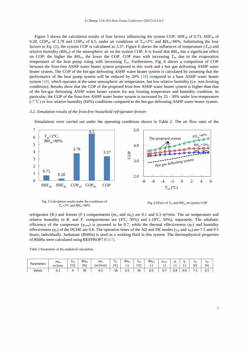
Figure 5 shows the calculation results of four factors influencing the system COP: SHFad of 0.73, SHFde of
0.28, COPad of 3.78 and COPde of 6.5, under air conditions of Toa=2ºC and RHoa=80%. Substituting the four
factors to Eq. (1), the system COP is calculated as 3.37. Figure 6 shows the influences of temperature (Toa) and
relative humidity (RHoa) of the atmospheric air on the system COP. It is found that RHoa has a significant effect
on COP: the higher the RHoa, the lower the COP. COP rises with increasing Toa due to the evaporation
temperature of the heat pump rising with increasing Toa. Furthermore, Fig. 6 shows a comparison of COP
between the frost-free ASHP water heater system proposed in this work and a hot–gas defrosting ASHP water
heater system. The COP of the hot-gas defrosting ASHP water heater system is calculated by assuming that the
performance of the heat pump system will be reduced by 20% [18] compared to a base ASHP water heater
system [19], which operates at the same atmospheric air temperature, but low relative humidity (i.e. non-frosting
conditions). Results show that the COP of the proposed frost-free ASHP water heater system is higher than that
of the hot-gas defrosting ASHP water heater system for any frosting temperature and humidity condition. In
particular, the COP of the frost-free ASHP water heater system is increased by 25 - 30% under low-temperature
(-7 ℃) or low relative humidity (60%) conditions compared to the hot-gas defrosting ASHP water heater system.
3.2. Simulation results of the frost-free household refrigerator-freezer
Simulations were carried out under the operating conditions shown in Table 2. The air flow rates of the
refrigerator (R.) and freezer (F.) compartments (mra and mfa) are 0.1 and 0.3 m³/min. The air temperature and
relative humidity in R. and F. compartments are (4ºC, 50%) and (-18ºC, 50%), separately. The adiabatic
efficiency of the compressor (ηcom) is assumed to be 0.7, while the thermal effectiveness (ηT) and humidity
effectiveness (ηx) of the DCHE are 0.8. The operation times of the AD and DE modes (τad and τde) are 7.5 and 0.5
hours, individually. Isobutane (R600a) is used as a working fluid in this system. The thermophysical properties
of R600a were calculated using REFPROP7.0 [17].
Table 2 Parameters of the analytical calculation
Parameters mRA
m3/min
TRA
[oC] RHRA
[%] mFA
[m3/min] TFA
[oC] RHFA
[-] TOA
[oC] RHOA
[-] ηcom
[-] ηx
[-] ηt
[-] τad
[h] τde
[h]
Values 0.1 4 50 0.3 -18 0.5 26 0.5 0.7 0.8 0.8 7.5 0.5
Fig. 5 Calculation results under the conditions of
Toa=2ºC and RHoa=80% Fig. 6 Effect of Toa and RHoa on system COP
0.730.28
3.78
6.5
3.37
0
1
2
3
4
5
6
7
1 2 3 4 5
Toa=2ºC,
RHoa=80%
SHFad SHFde COPad COPde COP
2.0
3.0
4.0
5.0
-8 -6 -4 -2 0 2 4 6
CO
P
Toa (ºC)
The proposed system
RHoa=80%
RHoa=70%

Li Zhang/ 12th IEA Heat Pump Conference (2017) O.1.6.3
8
Figure 7 shows the calculation results of the two factors those influence the system COP: γ of 0.95 and COPad
of 1.91. Substituting the two factors to Eq. (2), the system COP is calculated as 1.81.The overall cooling load
handled by the refrigeration system and electric power consumed by the compressor for one day are calculated
and the results are shown in Fig. 8. Among the overall cooling load of 7.42MJ/day, the cooling load of R.
compartment has a ratio of 60%. The electric power consumption of the compressor for one day is 1.13 kWh.
4. Experimental study of DCHEs
The results of the theoretical analysis show that the two proposed systems can prevent evaporators from
frosting and have high energy efficiency. In the following, we want to confirm experimentally whether a frost-
free state could be realized and whether the DCHE could be effectively regenerated under the condensation
temperature of heat pumps and refrigerators.
4.1. Experimental apparatus
A schematic diagram and photo of the experimental apparatus are shown in Fig. 9, comprising an air loop,
two brine loops: cooling brine and hot brine loops, a test section, an air rectification box and a convergence
chamber located separately upstream and downstream of the test section and some measurement instruments.
DCHE, meanwhile, is installed inside the test section. Air flows through the DCHE and contacts the desiccant to
exchange moisture with it, while cooling or hot brine inside the tubes is used to remove the adsorption heat
during the AD process, or heat the desiccant to regenerate it during the DE process. In this study, two DCHEs,
one coated by AQSOA (a kind of desiccant belonging to the zeolite family, developed by Mitsubishi Chemical
Corporation) and another coated by polymer sorbent (developed by Japan Exlan), were assessed experimentally.
The physical characteristics of the two DCHEs are shown in Table 3.
During adsorption experiments (AD Exp.), valves (V1 and V2) were opened and valves (V3 and V4) were
closed, so that the cooling brine was passed through the DCHE. The process air, conditioned to the required
temperature and humidity using a constant temperature and humidity air supplier, traversed the DCHE and
returned into the air supplied. The process air was dehumidified due to the DCHE adsorption process,
whereupon the adsorption heat was dissipated into the cooling brine. The air leaving the DCHE had a lower dew
point than that of the air at the DCHE inlet. When the humidity ratios of the air at the inlet and outlet of the
DCHE became equal, AD Exp. was finished. Subsequently, valves (V1 and V2) were closed, while others (V3
and V4) were opened, so that the hot brine was passed through the DCHE. Desorption experiment (DE Exp.)
was started, during which the desiccant released its moisture into the air. As a result, the desiccant is regenerated
and the air leaving the DCHE has a humidity ratio that exceeds that of the inlet air. When the humidity ratios of
the air at the inlet and outlet of the DCHE became equal, DE Exp. was finished. AD and DE experiments were
continuously conducted with at three cycles per test and the experimental data on the second or third cycle were
used in the following data reduction.
0
2
4
6
8
overall cooling load electricity
consumption
MJ/
day
4.08MJ
(1.13kWh)
60%
(R. compartment)
40%
(F. compartment)
7.42MJ
Fig. 7 Calculation results of γ, COPad and COP
Fig. 8 Overall cooling loads of R. and F. compartments
and the electric energy consumption for one day
0.95
1.911.81
γ COPad COPCOPad COP

Li Zhang/ 12th IEA Heat Pump Conference (2017) O.1.6.3
9
Table 3 Physical characteristics of the DCHEs
4.2. Experimental apparatus
∙ Whether can frost-free be realized?
Two experimental results corresponding to the two DCHEs, under the typical frosting air conditions of air-
source heat pumps in Japan: Toa=2ºC and RHoa=80% and the air temperature and humidity of freezer
compartment of household refrigerator-freezers: Toa=-18ºC and RHoa=60%, were shown in Figs. (10) and (11),
separately.
The evaluation criteria of the frost-free operation of the proposed heat pump and refrigerator are given as,
𝐷𝑃𝑎,𝑜𝑢𝑡 < 𝑇𝑒𝑣𝑎 (5)
where, DPa,out is the dew point of the DCHE outlet air and Teva is the evaporation temperature of the heat
pump or the refrigerator. Here, we assumed that Teva is 7ºC and 10ºC lower than the DCHE inlet air temperature
of the heat pump and refrigerator, individually.
From Fig. 10, the experimental result of the AQSOA-DCHE under heat pump operation condition, we found
the evaluation criteria were satisfied and the operation time satisfying the evaluation criteria was about 20
minutes. The experimental result of the polymer sorbent-DCHE under freezer operation condition, is shown in
Fig. 11. It is verified that the polymer sorbent is capable of adsorbing moisture from the air of -18ºC and the
operation time satisfying the evaluation criteria of the frost-free freezer is about 30 minutes.
∙ Whether can the desiccant be regenerated under the condensation temperature?
The AD experimental results shown in Figs. 10 and 11 were obtained after the DCHEs were regenerated by
passing 55ºC (the same temperature levels as the condensation temperature of the heat pump) and 43ºC (the
Parameters DCHE (AQSOA) DCHE (polymer sorbent)
Type of heat exchanger (HE) Aluminum fin and copper
tube HE
All aluminum, plate tube HE with
corrugated fins
Height of the DCHE-H (m) 0.242 0.2
Length of the DCHE-L (m) 0.3 0.5
Width of the DCHE-W (m) 0.0508 0.016
Fin pitch-Pf (m) 1.8 × 10⁻³ 1.2 × 10⁻³
Mass of dry desiccant-Md, dry (kg) 0.756 0.0878
Test section
Air flow meter
DCHE
Air flow
Brine pipe connected with brine tanks
Fig. 9 Experimental apparatus
Air flow meterVD2
VD1V1
V2
V3
V4
Test sectionCooling
brine
Hot
brineTa,in
RHa,inTa,out
RHa,out
ma
Tb,i, mb
Tb,o
Air supplier
Cooling HE
Dehumidifier
Humidifier
Heater
Fan
DC
HE
Process air
Rectification box
Convergence chamber
AQSOA DCHE Polymer sorbent DCHE

Li Zhang/ 12th IEA Heat Pump Conference (2017) O.1.6.3
10
same temperature levels as the condensation temperature of the refrigerator) hot brines through the DCHEs,
separately. Therefore, it is verified that the two kinds of desiccants: AQSOA and polymer sorbent, could be
regenerated under the condensation temperature and are suitable for the two proposed frost-free systems.
5. Conclusions
This paper introduced a proposed frost-free air-source heat pump and frost-free household refrigerator-
freezer. Theoretical study shows that the two proposed systems have high energy efficiency. Furthermore, it was
also experimentally verified that the frost-free operation of the proposed systems could be realized and DCHE
regenerated under the condensation temperatures of heat pumps and refrigerators.
Nomenclature
AD – adsorption
ASHP – air-source heat pump
COP – coefficient of performance
DCHE – desiccant-coated heat exchanger
DE – desorption
HR-F – household refrigerator-freezer
SHF – sensible heat factor
References
[1] Ameen F. R., Coney J. E., Sheppard C. G. W. Experimental study of warm-air defrosting of heat-pump evaporators. Rev. Int. Froid. 1993; 16 (1): pp. 13-18.
[2] Ding Y. J., Ma G. Y., Q. H., Jiang Y. Experiment investigation of reverse cycle defrosting methods on air source heat pump with TXV as the throttle regulator. Int. J. Refrig. 2004; 27: pp. 671-678.
[3] O’Neal D. L., Peterson K. T., Anand N. K. Effect of short-tube orifice size on the performance of an air source heat pump during the reverse-cycle defrost. Int. J. Refrig. 1991; 14 (1): pp. 52-57.
[4] Byun J. S., Lee J., Jeon C. D. Frost retardation of an air-source heat pump by the hot gas bypass method. Int. J. Refrig. 2008; 31: pp. 328-334.
[5] Tso C. P., Wong Y. W., Jolly P. G., Ng S. M. A comparison of hot-gas by pass and suction modulation method for partial load control in refrigerated shipping containers. Int. J. Refrig. 2001; 24 (6): pp. 544-553.
[6] Hoffenbecker N., Klein S. A., Reindl D. T. Hot gas defrost mode development and validation, Int. J. Refrig.2005; 28 (4): pp. 605-615.
[7] Yaqub M., Zubair S. M., Khan J. R. Performance evaluation of hot-gas by-pass capacity control schemes for refrigeration and air–conditioning system. Energy 2000; 25: pp. 543-561.
[8] Pradeep, B., David, F., Ryan, F.. Thermal analysis of the defrost cycle in a domestic freezer. Int. J. Refrig. 2010; 33: pp. 589-599.
-30
-20
-10
0
10
0 2 4 6 8 10 12 14 16 18 20
DP
a(º
C)
Elapsed time of AD Exp. (min)
Inlet air: (2ºC, 80%) , 163 m3/h
DPa,in
Assumed Teva:-5ºC
-45
-40
-35
-30
-25
-20
0 10 20 30 40 50 60
DP
(ºC
)
Elapsed time of AD Exp. (min)
Inlet air (-18ºC, 60%), 176m3/h
DPa,in
Assumed Teva: -28ºC
Fig. 10 Experimental result of AD Exp. of AQSOA-
DCHE for frost-free heat pump application Fig. 11 Experimental results of AD Exp. of polymer
sorbent DCHE for frost-free refrigerator application

Li Zhang/ 12th IEA Heat Pump Conference (2017) O.1.6.3
11
[9] Niederer, D. H. Frosting and defrosting effects on coil heat transfer, ASHRAE Transactions 1986; 82(1): pp. 467-473.
[10] Knabben, F. T., Hermes, C. J. L., Melo, C. 2011. Numerical and experimental investigation of the frosting and defrosting processes in no-frost evaporators. XI Ibero-American Congress of Refrigeration and Air conditioning – CIAR, Mexico.
[11] Bahman, A., Rossario, L., Rahman, M. M. Analysis of energy savings in a supermarket refrigeration/HVAC system. Applied Energy 2012; 98: pp. 11-21.
[12] Zakrzewskib,. Lokietek T., Hrycyk E. 2011. Defrosting of air cooler in refrigerating appliances and heat pump. The 23rd IIR International Congress of Refrigeration, Prague Czech Republic.
[13] Xie, G., Bansal, P. K. Analysis of defrosted water evaporation from three water trays in refrigerators. Appl. Therm. Eng. 2000; 20: pp. 651-669.
[14] Zhang L., Fujinawa T., Saikawa M. Theoretical study on a frost-free refrigerated display cabinet. Int. J. Refrig. (Accepted), http://dx.doi.org/10.1016/j.ijrefrig.2016.09.027
[15] Zhang L., Fujinawa T., Saikawa M. Theoretical study on a frost-free household refrigerator –freezer. Int. J. Refrig. 2016; 62: pp. 60-71.
[16] Zhang L., Fujinawa T., Saikawa M. A new method for preventing air-source heat pump water heater from frosting. Int. J. Refrig. 2012; 35: pp. 1327-1334.
[17] NIST reference fluid thermodynamic and transport properties database: version 7. 2007. [18] Byun J. S., Lee J., Jeon C. D. Frost retardation of an air-source heat pump by the hot gas bypass method.
Int. J. Refrig. 2008; 31: pp. 328-334. [19] Neksa P., Rekstad H., Zakeri G. R., Schiefloe P. A. CO2 –heat pump water heater: characteristics, system
design and experimental results. Int. J. Refrig. 1998; 21 (3): pp. 172-179.