Embed Size (px)
Citation preview

A New Method for the Tele-operation of
Aircraft
Dr. Paul Oh
James Hing

Presentation Outline
Market Potential State of the Art UAS Identifying Gaps - Motivation of Project Current Developments Notional Solution & Notional Experiment Optimal Goal Minimal Requirements for proof of concept Timeline

Market Potential
Search and rescue Firefighting Transport Commercial fishing Entertainment Overlooked Military applications Unlimited potential if we can not only
replicate manned flight through tele-operation but also improve it!
State of the Art of UAS
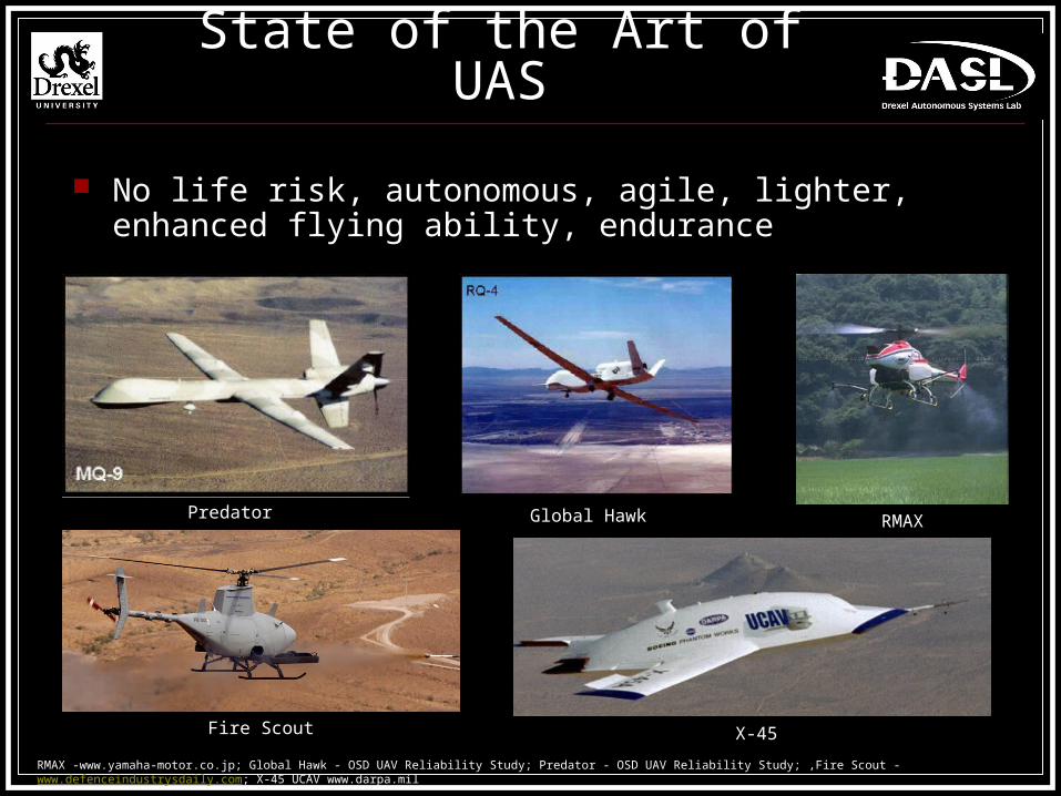
No life risk, autonomous, agile, lighter, enhanced flying ability, endurance
Predator Global Hawk RMAX
RMAX -www.yamaha-motor.co.jp; Global Hawk - OSD UAV Reliability Study; Predator - OSD UAV Reliability Study; ,Fire Scout - www.defenceindustrysdaily.com; X-45 UCAV www.darpa.mil
Fire Scout X-45
State of the art UAS
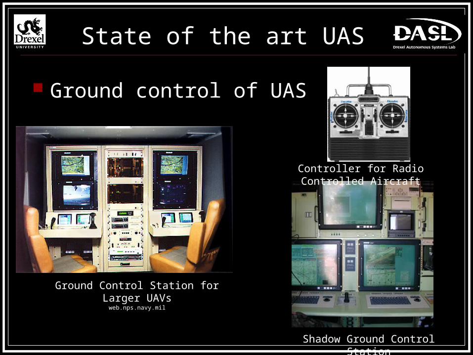
Ground control of UAS
Ground Control Station for Larger UAVsweb.nps.navy.mil
Shadow Ground Control Station
Controller for Radio Controlled Aircraft
Identifying Gaps
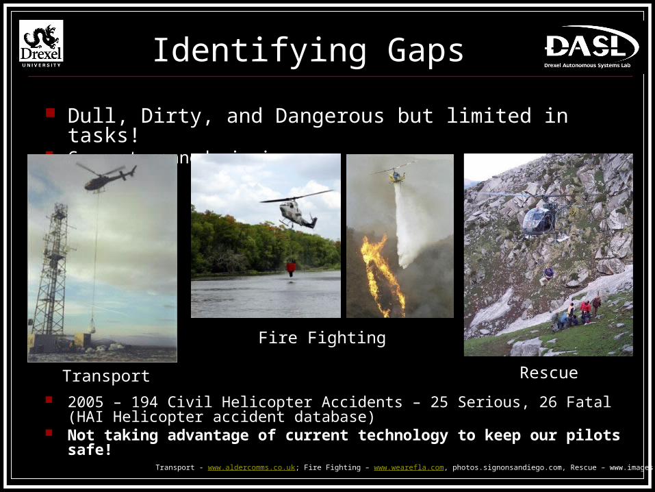
Dull, Dirty, and Dangerous but limited in tasks! Current manned missions
2005 – 194 Civil Helicopter Accidents – 25 Serious, 26 Fatal (HAI Helicopter accident database)
Not taking advantage of current technology to keep our pilots safe!
Rescue
Transport - www.aldercomms.co.uk; Fire Fighting – www.wearefla.com, photos.signonsandiego.com, Rescue – www.images.travelpod.com
Fire Fighting
Transport

Limitations of Current Autonomous Systems
Out of the Loop syndrome Sensor requirements increase with level of autonomy Automation unable to predict and program for all possible contingencies Extensive preplanning time Losing advantages of “pilot in the loop”!

Limitations of Current Remote Piloted Systems
Lower situational awareness Lack of physical / haptic cues and audio cues Small field of view from onboard camera Internal Pilots can not operate aircraft with the
efficiency of a manned aircraft

Current Developments
Significant academic research for improving pilot situation awareness
No one trying for maximum fidelity of inside the cockpit! – (ie. Motion, vibration, auditory)
Raytheon Universal Control System
Reality Vision – A2Tech
Alpine Wasp – TGR Helicorp

Notional Solution
Utilize advantages of both the pilot and UAS technology!
ETC GAT II - Helo
Boeing UnmannedLittle Bird
Manned Helicopter
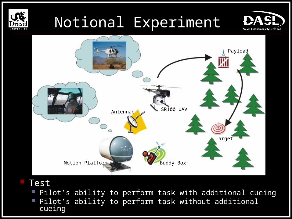
Notional Experiment
Test Pilot’s ability to perform task with additional cueing Pilot’s ability to perform task without additional cueing
Buddy Box
SR100 UAV
Payload
Target
Antennae
Motion Platform

Science to Enable Mission
Model Reference Adaptive Control (MRAC)
Little Bird Flight Qualities (Yaw, pitch, roll rates)
SR100 Flight Qualities (Yaw, pitch, roll rates)

Science to Enable Mission
Sensors - IMU, GPS, Compass, Altimeter*, Microphone*
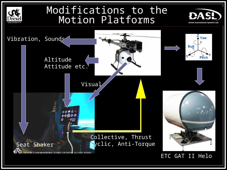
Modifications to the Motion Platforms
AltitudeAttitude etc.
Visual
Vibration, Sounds
Collective, ThrustCyclic, Anti-TorqueSeat Shaker
ETC GAT II Helo
Optimal Goal
Highest flight fidelity possible 6 DoF system with shaker seat Full High Definition Field of View SR100 with manned helicopter flight model Complete Sensor Suite Communications – LOS UHF, BLOS UHF,
Ku-band SATCOM Manned Helicopter Pilot RC Helicopter Pilot

Minimal Requirements
3 DoF system Two monitors
Forward looking External Load / Target
SR100 with no flight model Sensors – IMU, GPS, Altimeter, Compass Communications – RF, 802.11 Manned Helicopter Pilot RC Helicopter Pilot

3/19 3/26 4/2 4/9 4/16 4/23 4/30 5/7 5/14 5/21 5/28 6/4 6/11 6/18 6/25 7/2 7/9 7/16 7/23 7/30 8/6Presentation 3/23
Find Heli pilot & Heli RC PilotPWM signal interface
SR100 External Load CableSR100 Sensor Interface
Motion Platform ModificationSystem Integration
Flight Tests w/ Motion PlatformInitial Experiment
Analysis of Initial Experiment DataSafety Window / Flight Test with MRAC
Model Reference Adaptive ControlWrite Letter of Intent 7/2
Write Proposal 8/7
PWM Signal interface = Set up ground station that can accept data (ie. from the cyclic of the motion platform) and send out PWM signal matching the RC transmitter functionsSR100 External Load Cable = Build system that SR100 can deploy cable line to pick up external load (raise and lower)SR100 Sensor interface = Set up ground station that can accept sensor data from the SR100 and send it to the motion platform
Time Line
Questions & Discussion
Thank You