Embed Size (px)
Citation preview
A New Multi-Level Ground Water Monitoring System Utilizing Multi-Channel Tubing
By
Murray D. Einarson1,2 and John A. Cherry1
Manuscript accepted for publication in Ground Water Monitoring and Remediation
1University of Waterloo 200 University Avenue West
Waterloo, ON N2L 3G1 Canada 519-885-1211
2Now at Einarson & Associates 636 Middlefield Road Palo Alto, CA 94301
650-327-9682
©Einarson and Cherry, 2001
A New Multi-Level Ground Water Monitoring System Utilizing Multi-Channel Tubing
By
Murray D. Einarson and John A. Cherry
Abstract A new multi-level ground water monitoring system has been developed that uses custom-
extruded flexible 1.6-in. (4.1-cm) outside-diameter (O.D.) multi-channel HDPE tubing (referred
to as Continuous Multi-Channel Tubing [CMT]) to monitor as many as seven discrete zones
within a single borehole in either overburden or bedrock. Prior to inserting the tubing in the
borehole, ports are created that allow ground water to enter six outer pie-shaped channels
(nominal diameter = 0.5 in. [1.3 cm]) and a central hexagonal center channel (nominal diameter
= 0.4 in. [1 cm]) at different depths, facilitating the measurement of depth-discrete piezometric
heads and the collection of depth-discrete ground water samples. Sand packs and annular seals
between the various monitored zones can be installed using conventional tremie methods.
Alternatively, bentonite packers and pre-packed sand packs have been developed that are
attached to the tubing at the ground surface, facilitating precise positioning of annular seals and
sand packs. Inflatable rubber packers for permanent or temporary installations in bedrock
aquifers are currently undergoing site trials. Hydraulic heads are measured with conventional
water level meters or electronic pressure transducers to generate vertical profiles of hydraulic
head. Ground water samples are collected using peristaltic pumps, small-diameter bailers,
inertial lift pumps, or small-diameter canister samplers. For monitoring hydrophobic organic
compounds, the CMT tubing is susceptible to both positive and negative biases caused by
sorption, desorption, and diffusion. These biases can be minimized by (1) purging the channels
©Einarson and Cherry, 2001 1
prior to sampling, (2) collecting samples from separate 0.25-inch (0.64 cm) O.D. Teflon®
sampling tubing inserted to the bottom of each sampling channel, or (3) collecting the samples
down-hole using sampling devices positioned next to the intake ports. Currently, more than
1000 CMT multi-level wells have been installed in North America and Europe to depths up to
260 feet (79 m) below ground surface. These wells have been installed in boreholes created in
overburden and bedrock using a wide range of drilling equipment including sonic, air rotary,
diamond-bit coring, hollow-stem auger, and direct push. This paper presents a discussion of three
field trials of the system, demonstrating its versatility and illustrating the type of depth-discrete
data that can be collected with the system.
Introduction Many investigations have shown that contaminant plumes are typically complex zones
that exhibit large variations in concentration over small vertical distances. These variations are
caused by spatial and temporal variability of the contaminant sources and heterogeneity of the
geologic materials. In sand aquifers, large vertical concentration variability within plumes is
enhanced by weak transverse vertical dispersion that preserves the variability over large travel
distances (Reinhard et al. 1984; Robertson et al. 1991; van der Kamp et al. 1994). Weak
dispersion has been documented during natural gradient tracer experiments in which the tracers
were monitored intensively using multi-level depth-discrete samplers (Mackay et al. 1986a;
Mackay et al. 1986b; Garabedian et al. 1991; LeBlanc et al. 1994).
Conventional monitoring wells are often ineffective for discerning the details of the
concentration distribution in plumes and particularly for locating the highest concentration zones
because the well screens provide water samples that are a mixture of waters of different
composition from various depths (Robbins 1989; Martin-Hayden et al. 1991; Robbins and
©Einarson and Cherry, 2001 2
Martin-Hayden 1991). Nested monitoring wells (i.e., two or more individual wells installed to
different depths in the same borehole) can yield depth-discrete samples but their use is
discouraged because of the difficulty in installing reliable seals between the different well
screens (USEPA, 1986). Clusters of conventional monitoring wells (i.e., closely-spaced wells
installed in individual boreholes but completed to different depths) are an alternative to nested
wells but commonly do not monitor more than two or three depth intervals because of the
economic limitation on the number of wells used in each cluster. To overcome these limitations,
multi-level monitoring systems that provide water samples from many depth-discrete levels or
ports in a single monitoring hole have been used, such as those described by Pickens et al.
(1978), Cherry and Johnson (1982), and Black and Patton (1986).
This paper describes a new low-cost permanent multi-level monitoring system that can be
used to collect ground water samples and measure hydraulic heads from up to seven discrete
zones in one borehole. The system utilizes a single length of custom-extruded flexible tubing,
facilitating the installation of reliable annular seals between the monitoring zones using
conventional well construction methods where annular materials (e.g., sand and bentonite
pellets) are added from the ground surface. Bentonite packers have also been used that allow the
entire multi-level well to be constructed above ground and then inserted into a borehole. By
using the bentonite packers, seals of exact dimensions and position can be installed. A
modification of the system using water-inflated rubber packers for use in rock boreholes is
currently undergoing site trials.
©Einarson and Cherry, 2001 3
Materials and Methods
Continuous Multi-Channel Tubing (CMT)
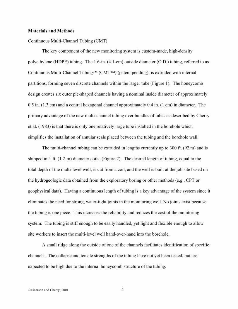
The key component of the new monitoring system is custom-made, high-density
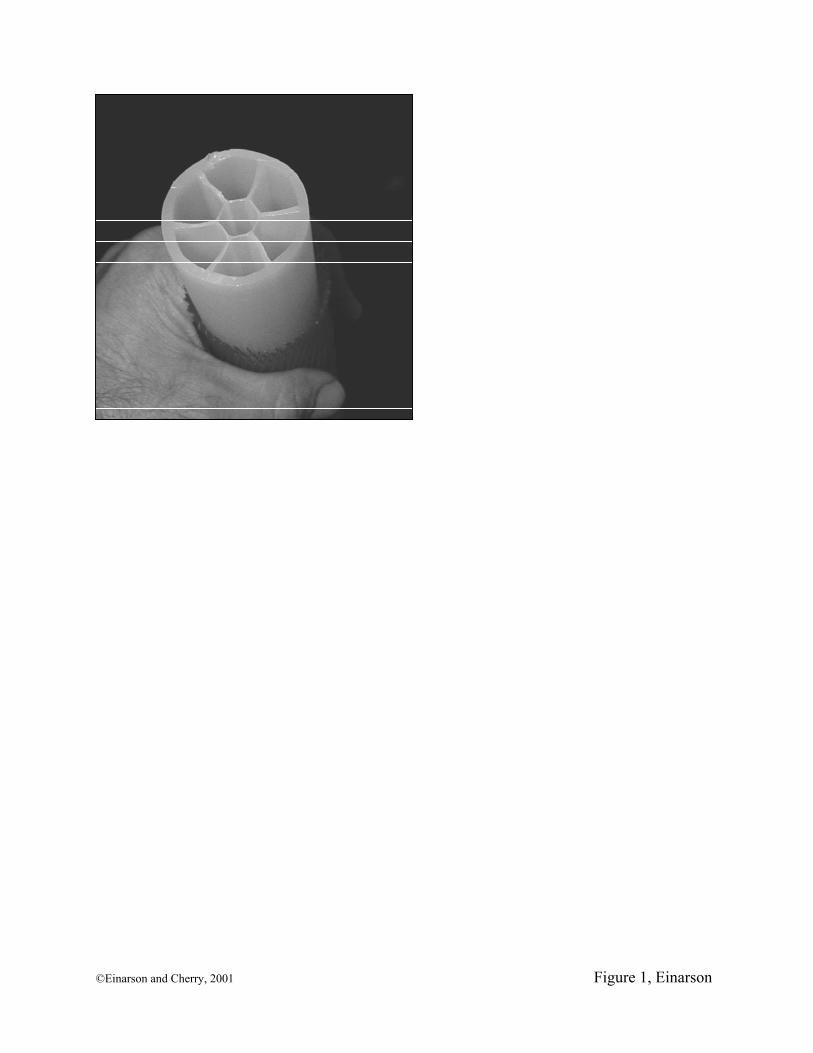
polyethylene (HDPE) tubing. The 1.6-in. (4.1-cm) outside diameter (O.D.) tubing, referred to as
Continuous Multi-Channel Tubing™ (CMT™) (patent pending), is extruded with internal
partitions, forming seven discrete channels within the larger tube (Figure 1). The honeycomb
design creates six outer pie-shaped channels having a nominal inside diameter of approximately
0.5 in. (1.3 cm) and a central hexagonal channel approximately 0.4 in. (1 cm) in diameter. The
primary advantage of the new multi-channel tubing over bundles of tubes as described by Cherry
et al. (1983) is that there is only one relatively large tube installed in the borehole which
simplifies the installation of annular seals placed between the tubing and the borehole wall.
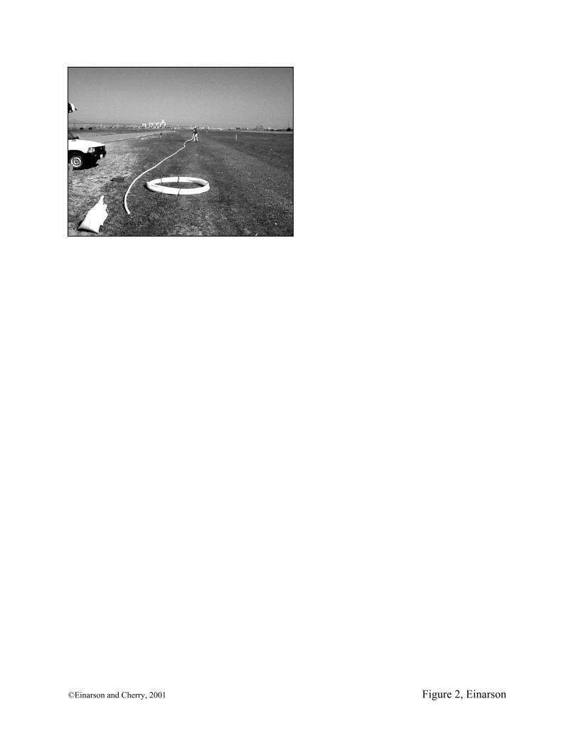
The multi-channel tubing can be extruded in lengths currently up to 300 ft. (92 m) and is
shipped in 4-ft. (1.2-m) diameter coils (Figure 2). The desired length of tubing, equal to the
total depth of the multi-level well, is cut from a coil, and the well is built at the job site based on
the hydrogeologic data obtained from the exploratory boring or other methods (e.g., CPT or
geophysical data). Having a continuous length of tubing is a key advantage of the system since it
eliminates the need for strong, water-tight joints in the monitoring well. No joints exist because
the tubing is one piece. This increases the reliability and reduces the cost of the monitoring
system. The tubing is stiff enough to be easily handled, yet light and flexible enough to allow
site workers to insert the multi-level well hand-over-hand into the borehole.
A small ridge along the outside of one of the channels facilitates identification of specific
channels. The collapse and tensile strengths of the tubing have not yet been tested, but are
expected to be high due to the internal honeycomb structure of the tubing.
©Einarson and Cherry, 2001 4
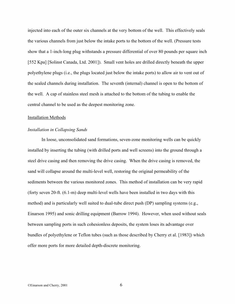
Intake Ports and Screens
Construction of the intake ports and screens is done before the CMT tubing is inserted
into the borehole. Depth-discrete intake ports are created by drilling or cutting 0.38 in. (0.95
cm) holes through the exterior wall of the tubing into each of the channels at the desired depths.
Channel 1 ports correspond to the shallowest monitoring interval; channel 2 ports are drilled
further down the tubing (i.e. to monitor a deeper zone), and so forth. The central channel,
channel 7, is open to the bottom of the multi-level well. In this way, the ports of the various
channels are staggered both vertically and around the perimeter of the multi-channel tubing.
Typically, each channel is hydraulically connected to only one monitoring interval. However,
the well can be constructed with two channels open to the same interval: One channel can be
used for measuring water levels; the other for collecting groundwater samples with a dedicated
sampling pump. Since two channels are used at each depth, constructing a well this way reduces
the number of intervals that can be monitored. For most of the installations performed to date,
an intake interval of 4 in. (10 cm) has been created by drilling four holes one inch (2.5 cm) apart.
The depth interval of the intake ports can be increased simply by drilling more holes.
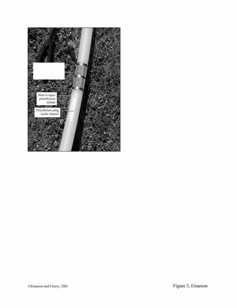
Well screens are constructed by wrapping synthetic or stainless steel fabric mesh
completely around the tubing in the interval containing the ports (Figure 3). The mesh is secured
to the tubing using stainless steel clamps. The size of the mesh openings can be selected based on
the grain-size distribution of the particular water-bearing zone being monitored. However, a 100
mesh stainless-steel screen having an open area of approximately 0.006 in. (0.15 mm) has been
used successfully for most of the installations performed to date.
Stagnant water in the tubing below the intake ports is hydraulically isolated by plugging
the channels a few inches below each intake port. This has been done by injecting a small
amount of a polyethylene sealant into each channel (Figure 3). Polyethylene plugs are also
©Einarson and Cherry, 2001 5
injected into each of the outer six channels at the very bottom of the well. This effectively seals
the various channels from just below the intake ports to the bottom of the well. (Pressure tests
show that a 1-inch-long plug withstands a pressure differential of over 80 pounds per square inch
[552 Kpa] [Solinst Canada, Ltd. 2001]). Small vent holes are drilled directly beneath the upper
polyethylene plugs (i.e., the plugs located just below the intake ports) to allow air to vent out of
the sealed channels during installation. The seventh (internal) channel is open to the bottom of
the well. A cap of stainless steel mesh is attached to the bottom of the tubing to enable the
central channel to be used as the deepest monitoring zone.
Installation Methods
Installation in Collapsing Sands
In loose, unconsolidated sand formations, seven-zone monitoring wells can be quickly
installed by inserting the tubing (with drilled ports and well screens) into the ground through a
steel drive casing and then removing the drive casing. When the drive casing is removed, the
sand will collapse around the multi-level well, restoring the original permeability of the
sediments between the various monitored zones. This method of installation can be very rapid
(forty seven 20-ft. (6.1-m) deep multi-level wells have been installed in two days with this
method) and is particularly well suited to dual-tube direct push (DP) sampling systems (e.g.,
Einarson 1995) and sonic drilling equipment (Barrow 1994). However, when used without seals
between sampling ports in such cohesionless deposits, the system loses its advantage over
bundles of polyethylene or Teflon tubes (such as those described by Cherry et al. [1983]) which
offer more ports for more detailed depth-discrete monitoring.
©Einarson and Cherry, 2001 6
Installation Using Conventional Well Construction Techniques to Install Sand Packs and Annular Seals
In clay-rich or indurated sediments and bedrock, the borehole usually will not collapse
and other methods are necessary to seal the annulus between the various intake ports. At these
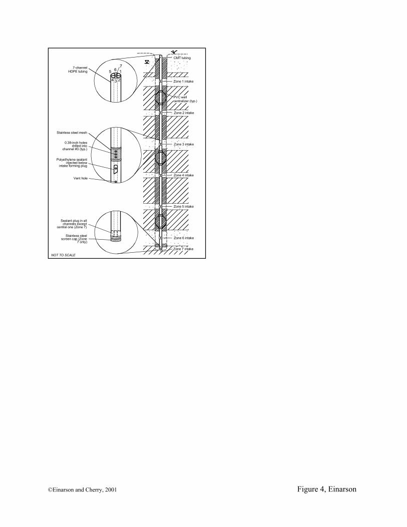
sites, alternating lifts of sand and bentonite have been added to the annular space from the
ground surface using conventional well construction techniques (Figure 4). First, ports are
created and stainless steel screens are attached to the tubing at the ground surface as discussed
above. Next, the CMT tubing is lowered to the bottom of the borehole either in an open hole (if
the borehole will stay open) or inside steel casing or hollow-stem augers. Alternating lifts of
sand and bentonite pellets are poured into the annular space from the ground surface to specific
depths according to the well design. In an open hole, materials can be added via a tremie pipe to
ensure that no bridging occurs. In cased holes (steel drive casing or hollow-stem augers), the
sand and bentonite pellets are usually poured from the surface without a tremie pipe. The casing
or augers are removed incrementally as the annular materials are added. In either case, the depth
of the sand and bentonite is measured frequently during construction using a weighted measuring
line.
Because the tubing is flexible, closely-spaced (e.g., every 15 ft. [4.6 m]) steel or PVC
centralizers have been attached to the CMT tubing to ensure that the tubing is centered in the
borehole during construction. The use of centralizers can be avoided by using a 2 in. (5 cm)
metal or polyvinyl chloride (PVC) insertion pipe to center the CMT tubing during well
construction. The insertion pipe is placed in the borehole prior to inserting the CMT tubing.
Annular materials are poured from the surface and the insertion pipe is removed from the
borehole incrementally along with the steel casing or augers (if used). Two centralizers (20 ft.
[6.1 m] apart) have been attached to the bottom of the insertion pipe to keep the CMT tubing
©Einarson and Cherry, 2001 7
centered in the borehole during construction. In this way, the annular space between the
insertion pipe and the borehole (or casing/augers) is unobstructed by centralizers, minimizing the
likelihood of bridging the bentonite pellets and tangling the measuring line. For deep wells
where the water table is shallow, coated bentonite pellets have been used. Coated pellets prevent
the bentonite from swelling prematurely as the pellets fall through standing water. Premature
hydration of the pellets can create undesirable bridging in the annulus, preventing the pellets
from falling to the desired depth.
Installation in Non-Collapsing Sediments Using Bentonite Packers and Pre-Packed Sand Packs
Installing seven-zone multi-level wells using conventional well construction techniques
described above requires precise placement of annular seals and sand packs, especially for
shallow wells where each seal may only be a few feet thick. This degree of precision may not be
possible at many sites using conventional well construction methods where some amount of
sloughing of native materials and/or overfilling of materials often occurs. Consequently,
bentonite packer seals were developed that can be attached to the CMT tubing prior to insertion
into the borehole. This eliminates the need to add annular materials from the ground surface and
offers greater precision in the construction of shallow multi-level wells. Sand packs can also be
attached around the well screens in a similar fashion.
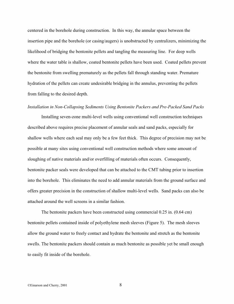
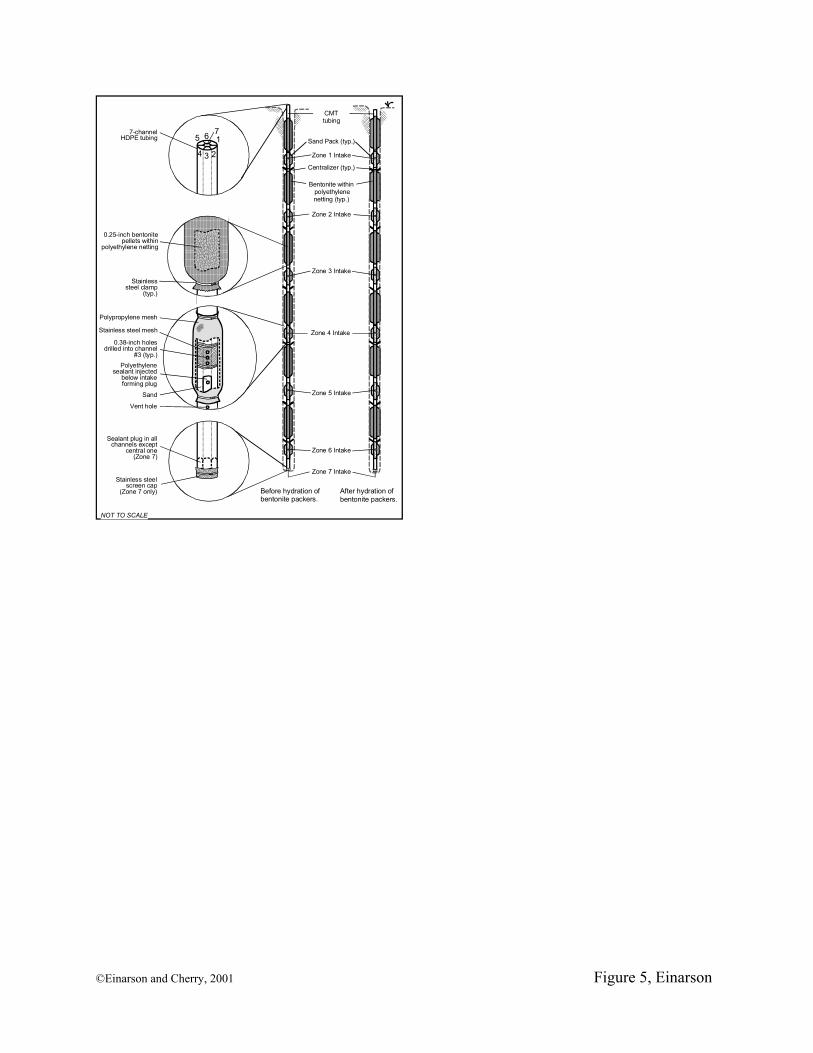
The bentonite packers have been constructed using commercial 0.25 in. (0.64 cm)
bentonite pellets contained inside of polyethylene mesh sleeves (Figure 5). The mesh sleeves
allow the ground water to freely contact and hydrate the bentonite and stretch as the bentonite
swells. The bentonite packers should contain as much bentonite as possible yet be small enough
to easily fit inside of the borehole.
©Einarson and Cherry, 2001 8
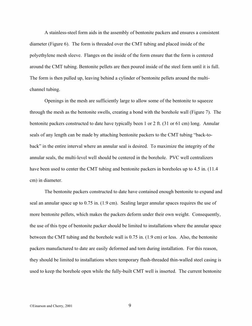
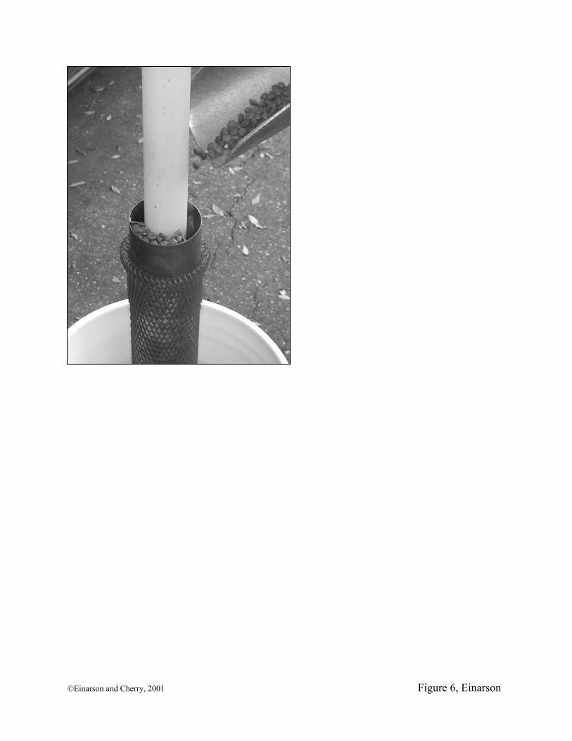
A stainless-steel form aids in the assembly of bentonite packers and ensures a consistent
diameter (Figure 6). The form is threaded over the CMT tubing and placed inside of the
polyethylene mesh sleeve. Flanges on the inside of the form ensure that the form is centered
around the CMT tubing. Bentonite pellets are then poured inside of the steel form until it is full.
The form is then pulled up, leaving behind a cylinder of bentonite pellets around the multi-
channel tubing.
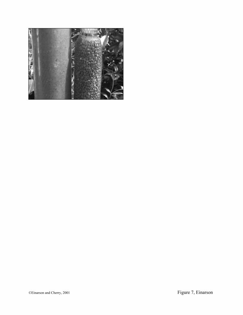
Openings in the mesh are sufficiently large to allow some of the bentonite to squeeze
through the mesh as the bentonite swells, creating a bond with the borehole wall (Figure 7). The
bentonite packers constructed to date have typically been 1 or 2 ft. (31 or 61 cm) long. Annular
seals of any length can be made by attaching bentonite packers to the CMT tubing “back-to-
back” in the entire interval where an annular seal is desired. To maximize the integrity of the
annular seals, the multi-level well should be centered in the borehole. PVC well centralizers
have been used to center the CMT tubing and bentonite packers in boreholes up to 4.5 in. (11.4
cm) in diameter.
The bentonite packers constructed to date have contained enough bentonite to expand and
seal an annular space up to 0.75 in. (1.9 cm). Sealing larger annular spaces requires the use of
more bentonite pellets, which makes the packers deform under their own weight. Consequently,
the use of this type of bentonite packer should be limited to installations where the annular space
between the CMT tubing and the borehole wall is 0.75 in. (1.9 cm) or less. Also, the bentonite
packers manufactured to date are easily deformed and torn during installation. For this reason,
they should be limited to installations where temporary flush-threaded thin-walled steel casing is
used to keep the borehole open while the fully-built CMT well is inserted. The current bentonite
©Einarson and Cherry, 2001 9
packers are not appropriate for installations inside of hollow-stem augers because the packers
will not swell sufficiently to seal the relatively large annular space created by the auger flights.
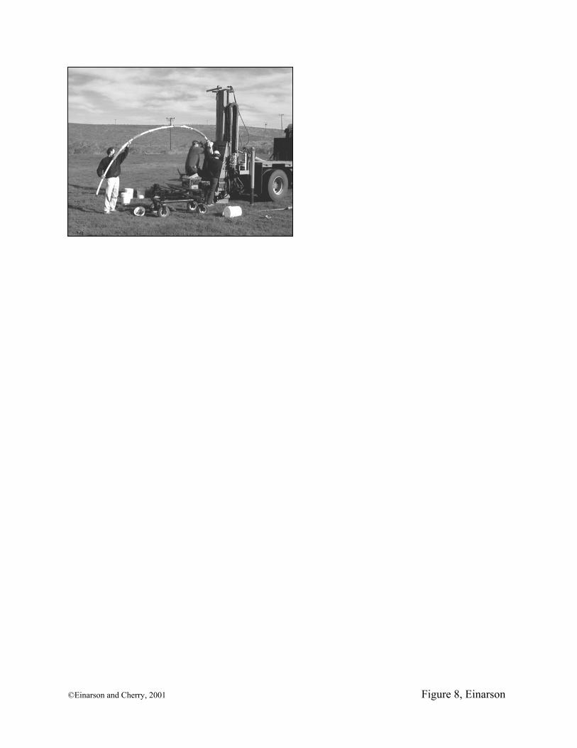
Once all of the bentonite packers, sand packs, and centralizers have been attached to the
CMT tubing, the tubing is inserted into the steel drive casing hand-over-hand to the bottom of
the borehole (Figure 8). Insertion of the tubing into a 100-ft. (31-m) deep borehole takes
approximately 10 minutes. After the well is in place, the temporary steel casing is removed,
allowing ground water to hydrate the bentonite packers. As they hydrate, the bentonite packers
swell, sealing the borehole between the monitoring zones within three or four hours. More than
200 installations of CMT multi-level system equipped with bentonite packer seals and pre-
packed sand packs have been successfully performed to date, including an installation to a depth
of 195 ft. (60 m) using a sonic drill rig.
Well Development, Measuring Hydraulic Head, Hydraulic Testing, and Collecting Ground Water Samples
Well Development
Requirements for developing the multi-level wells vary depending on the type of
installation. If no foreign water is introduced to the aquifer during installation, well development
can be limited to thorough purging to remove introduced fines from the borehole wall and
enhance the hydraulic connection with the formation. If foreign water or other drilling fluids are
used during drilling and well installation, removal of large quantities of water may be necessary.
Limited well development can be performed using small-diameter sampling pumps.
However, the extraction rate of the pumps is small and extracting large volumes of water (e.g.,
hundreds of gallons) is not cost effective. Also, the low extraction rates of small-diameter
sampling pumps creates a relatively weak hydraulic stress, resulting in a limited ability to
©Einarson and Cherry, 2001 10
remove introduced fines and/or smeared soil from the borehole wall, especially in large-diameter
borings drilled in relatively permeable formations.
An innovative gas-lift/vacuum extraction system has been developed to simultaneously
extract ground water from all seven zones. This system, which is a variation of standard air-lift
well development techniques, has been used to develop 1300 gallons (4921 L) of water at a flow
rate of 1.1 gallons per minute (4.2 liters per minute) from a multi-level well where the static
depth to water was 100 ft. (31 m) below ground surface (bgs). The gas-lift/vacuum extraction
system is described in more detail by Einarson (2001).
Measuring Hydraulic Heads
Depth to ground water measurements can be made using commercially-available water
level meters (e.g., well sounders). Water level measurements greater than 150 ft. (46 m) bgs
have been made inside of the CMT tubing using a small-diameter water level meter
manufactured by Solinst Canada, Ltd. If continuous pressure measurements are desired, pressure
transducers small enough to fit down the CMT channels ( Druck Mod. PDCR 35D-8070) are
commercially available (Solinst Canada, Ltd. 2001).
Hydraulic Testing
The authors are aware of several sites where environmental consultants have performed
rising- and/or falling-head tests (i.e., slug tests) in CMT wells, although the authors have not yet
performed such tests themselves. The availability of small-diameter transducers connected to
dataloggers facilitates the recording of rapid hydraulic responses in permeable aquifers that
would not be possible with hand measurements. Calculation of formation hydraulic conductivity
using conventional analytical solutions may be complicated, however, by the pie-shaped
geometry of the CMT tubing. The potential error associated with the non-radial CMT well
©Einarson and Cherry, 2001 11
geometry is a function of the relative difference between the sand pack and formation hydraulic
conductivity, and could possibly be addressed using a skin factor applied to the analytical
solution (Butler 2001). Hydraulic testing in CMT wells is the subject of ongoing research and
testing by the authors and other collaborators.
Collecting Ground Water Samples
Ground water samples can be collected from the CMT multi-level system using a variety
of methods including peristaltic pumps (providing that the water level is within the limits of
suction lift), inertial lift pumps (e.g., Waterra® pumps [Rannie and Nadon 1985]), and small-
diameter bailers. Small-diameter down-hole canister samplers such as those described by
Pankow et al. (1985) and Johnson et al. (1987) may also be used to collect ground water samples
from the bottom of each channel directly adjacent to the intake ports. Due to the small internal
diameter of the CMT channels, no commercially-available submersible or bladder pumps
currently exist for the system, although an innovative double-valve sampling pump is under
development (Solinst Canada, Ltd. 2001).
Water samples have been successfully collected from a CMT multi-level well at a flow
rate of 120 mL/min using a hand-operated 0.25-in. (0.64-cm) O.D. Teflon inertial lift pump
where the static depth of ground water was 100 ft. (31 m) bgs. The purge volume of the internal
channels is approximately 40 mL per ft. (131 mL/m) of tubing, which minimizes the amount of
purge water that needs to be removed prior to sampling.
All sampling devices can impart biases in analytical results due to volatilization of
organic contaminants, sorption/desorption of hydrophobic solutes onto/off of sample tubing, pH
changes that may precipitate dissolved metals, etc. The reader is referred to Parker (1994) for a
©Einarson and Cherry, 2001 12
thorough literature review of the biases associated with various ground water sample collection
methods.
Potential Chemical Biases Associated with CMT System
Because the CMT monitoring system utilizes one continuous length of tubing, the tubing
must be flexible enough to bend 90 degrees when it is being inserted into a borehole. This
degree of flexibility requires that the system be made of polymeric tubing. A drawback of
polymeric tubing as a well construction material is that it is less resistant to sorption (adsorption
and absorption) of hydrophobic organic contaminants than rigid well construction materials like
stainless steel or PVC. Chemical biases associated with polymeric tubing have been described
by many authors (see below) and are therefore discussed only briefly in this paper.
Sorption/Desorption of Organic Contaminants onto/off-of the Interior Walls of the CMT Tubing During Sampling
A negative sampling bias can occur if organic contaminants sorb onto the interior walls
of the HDPE CMT tubing while the water sample is pumped up from the sampling port to the
ground surface. For HDPE tubing, the amount of contaminant mass lost from the sample is
proportional to the residence time within the channel and the hydrophobicity of the organic
solute (Hewitt 1994; Parker and Ranney 1998). Conversely, a positive bias can occur during a
later sampling event if organic molecules desorb from the tubing into the subsequent ground
water sample (Barcelona et al. 1985; Barker et al. 1987; Gillham and O’Hannesin 1990; Parker
and Ranney 1998).
Diffusion of Organic Contaminants from the Aquifer Surrounding the CMT Well
Barker et al. (1987), Gillham (1989), and Gillham and O’Hannesin (1990) showed that in
wells or piezometers constructed of polyethylene tubing, hydrophobic organic compounds can
diffuse through the tubing from the aquifer into water inside the tubing in response to
©Einarson and Cherry, 2001 13
concentration gradients. In the case where the intake of a polyethylene well is located below a
high-strength contaminant plume, hydrophobic volatile organic compounds (VOCs) detected in
samples collected from the well may simply be a result of diffusion through the tubing from the
shallow contaminant plume surrounding the exterior of the tubing. Such detections could lead
site investigators to falsely conclude that the VOC contamination extends to a greater depth than
it actually does. With the CMT system, the potential sampling bias is further complicated by the
honeycomb structure of the tubing. During the time between sampling events, solutes present in
one or more of the channels could diffuse into adjacent channels, resulting in the false detection
of the solutes in one or more of the multi-level sampling intervals.
Leaching of Organic Compounds from HDPE Tubing and/or Polyethylene Hot-Melt Sealant
Leaching of organic compounds from the CMT well materials can result in a potential
positive sampling bias. Leaching of trace organic compounds from polymer tubing has been
evaluated by several researchers, including Junk et al. (1974), Curran and Tomson (1983),
Barcelona et al. (1985), Parker and Ranney (1997), Parker and Ranney (1998), and Ranney and
Parker (1998). Those studies indicate that polyethylene tubing, by itself, is either inert or does
not impart significant amounts of common target organic compounds to water that has been in
contact with the tubing. As discussed above, however, a commercial hot-melt polyethylene
adhesive (Arrow C-7 Hot-Melt Sealant, Arrow Fastener Co. Inc., Saddle Brook, NJ) has been
used to seal the various channels below the sampling ports. The sealant is injected using a high-
temperature glue gun. Leaching of trace organic compounds from the polyethylene sealant is
another potential source of positive sample bias with the system. The potential bias caused by
leaching of organic compounds from the polyethylene tubing and the hot-melt polyethylene
sealant was investigated by performing static leaching tests on virgin materials used to construct
©Einarson and Cherry, 2001 14
the CMT wells. Details of the leaching tests, including analytes and detection limits, are
presented by Einarson (2001). In summary, samples of distilled water that had been in contact
with (1) virgin CMT polyethylene tubing and (2) hardened hot-melt sealant for one week were
analyzed for a comprehensive suite of volatile organic compounds using gas
chromatograph/mass spectrometry (GC/MS) methods in accordance with US EPA Method
8260B. No VOCs were detected in the water that had been in contact with the polyethylene.
Toluene was detected at a concentration of 25.5 µg/L in the sample of water that had been in
contact with the hot-melt sealant, however. While the detection of toluene in the leachate sample
suggests that there may be a systematic positive bias caused by leaching of the polyethylene
sealant in the CMT wells, two years of field monitoring suggests otherwise. Only one
anomalous detection of toluene has been measured in hundreds of analyses of ground water
samples collected from CMT wells. The well in question is completed in a fine-grained
formation that yields little water during sampling. Because the rate of recovery is so slow, it has
not been possible to purge the well before sampling. Only a foot or two of ground water is
typically present in the channel, and initial analyses of ground water collected from the channel
two weeks after the well was installed contained toluene at a concentration of 5 µg/L. The fact
that toluene has not been detected in other wells that are purged prior to sampling suggests that
the potential sampling bias caused by leaching of the polyethylene sealant is minor due to (1)
reduced contact time under dynamic sampling conditions (see Parker and Ranney [1998]) or (2)
a decrease in the amount of toluene leached from the sealant over time as the compound ages.
In any case, recent advancements in the design of the sampling ports utilize mechanical
expansion plugs instead of the hot-melt polyethylene sealant (Solinst Canada, Ltd. 2001). This
will eliminate the need for the chemical sealant and potential biases associated with its use.
©Einarson and Cherry, 2001 15
Sorption and Leaching of Metals and Other Inorganic Solutes
Previous studies indicate that while plastic tubing is generally inert with regard to anionic
solutes, positively-charged solutes are subject to cation exchange reactions (Ranney and Parker
1998). Several laboratory studies have been performed to evaluate the significance of these
processes in ground water monitoring applications, however few quantitative studies have been
performed using HDPE tubing. Results of the limited studies indicate that negative biases due to
sorption onto polymeric tubing is minor compared to stainless steel. Sorption and/or leaching of
metals from the stainless steel screens and clips used to construct the CMT wells may be of
concern, however. In order to minimize these biases, the CMT well screens could be constructed
with plastic mesh and plastic ties. Readers are referred to Parker et al. (1990), Hewitt (1992),
Hewitt (1994), and Ranney and Parker (1998) for additional discussions of the applicability of
using polymeric tubing for monitoring trace concentrations of dissolved metals and other ionic
contaminants.
Suggested Sampling Protocol to Minimize Chemical Biases
Chemical biases caused by sorption/desorption and diffusion of dissolved hydrophobic
organic contaminants through the CMT tubing can be minimized by (1) thorough purging of
each channel prior to sampling and (2) collecting ground water samples from separate 0.25-in.
(0.64-cm) diameter Teflon sampling tubing placed inside the channels to depths corresponding to
the various intake ports. That way, ground water from the formation is drawn through the ports
and immediately enters the Teflon sampling tubing where the sorption/diffusion of the solutes is
reduced. Similarly, contact between the ground water sample and the CMT tubing could be
minimized by using down-hole canister samplers similar to those described by Pankow (1985)
and Johnson (1987), although those samplers have not yet been tested with the CMT system.
©Einarson and Cherry, 2001 16
Trial Installations
Canadian Forces Base Borden, Ontario, Canada
Two CMT multi-level wells (ME-1 & ME-2) were installed at Canadian Forces Base
(CFB) Borden in Ontario, Canada. The CMT wells were installed in a well-studied part of the
base where a controlled release of tetrachloroethylene (PCE) took place in 1991 (Brewster et al.
1995). During that experiment, 771 liters of PCE was injected into a shallow sand aquifer
isolated within a 9 by 9 meter sheet pile enclosure. Sheet piles extended through the surficial
aquifer into the underlying clay till aquitard.
The hydrogeology in the vicinity of the 9 by 9 meter cell is well understood as a result of
detailed field studies performed by Foley (1992) and Morrison (1998). In those investigations,
over 105 boreholes were drilled in and around the 9 by 9 meter cell, into which over 50 single- or
multi-level monitoring wells were installed.
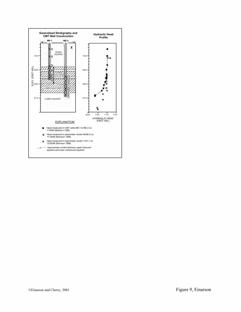
The study area is underlain by a 15-ft. (4.6-m) thick surficial sandy aquifer referred to as
the Borden Aquifer (Figure 9). Unconfined ground water occurs within that unit at a depth
ranging seasonally from 3 to 6 ft. (0.9 to 1.8 m) bgs. A 20- to 28-ft. (6.1- to 8.5-m) thick clay
aquitard unconformably underlies the Upper Aquifer in the study area, separating it from the
underlying Lower Aquifer (Morrison 1998).
The clay aquitard can be divided into an upper and lower unit based on lithology and
post-depositional weathering. The upper unit is about 10 to 15 ft. (3.1 to 4.6 m) thick and is
composed of silty clay containing discontinuous sandy laminae and thin sand interbeds. Vertical
cracks and fissures are common in the upper unit due to erosion and desiccation following the
Late Wisconsin glacial retreat. The lower part of the aquitard is approximately 6 to 10 ft. ( 2 to
3m) thick and is composed of unweathered, unfractured silty clay and clay. The Lower Aquifer
in the vicinity of the 9 by 9 meter cell is relatively thin, consisting of a 6- to 10-ft. (2- to 3-m)
©Einarson and Cherry, 2001 17
thick continuous layer of medium- to coarse-grained sand. Piezometric heads within the lower
aquifer fluctuate between approximately 697 and 700 ft. (212.5 and 213.4 m) above sea level
(FASL) in the last few years (Morrison 1998).
Detailed hydraulic head monitoring by Foley (1992) and Morrison (1998) showed a
strong downward hydraulic gradient between the Upper and Lower aquifers. Hydraulic head
profiles measured in 1996 in two piezometer clusters located near CMT wells ME-1/ME-2 are
shown in Figure 9. Piezometer cluster ML96-2 is located approximately 80 ft. (24 m) northwest
of CMT wells ME-1/ME2. Piezometer cluster 1191-1 is located about 40 ft. (12 m) south of the
two CMT wells. A head change in excess of 12 ft. (3.6 m) was measured in 1996 between
piezometers installed in the upper aquitard and the lower aquifer. Core logs and hydraulic head
data from those and other piezometers suggests that nearly all of the head change occurs across
the basal portion of the clay aquitard, where the sandy interbeds and vertical fractures are absent.
The upper and middle portions of the clay aquitard are suspected of being hydraulically active
(i.e., hydraulically connected to the upper aquifer) due to the abundance of coarse-grained
interbeds and desiccation fractures (Morrison 1998).
CMT wells ME-1 and ME-2 were installed in June and December 1998, respectively,
with a total of 14 ports in the Upper and Lower aquifers and in the intervening clay aquitard
(Figure 9). The wells were installed in boreholes created with a dual-tube direct-push sampling
system described by Einarson (1995). Continuous soil cores were collected and logged in detail
prior to selecting the screened intervals of the multi-level wells. After the coring was finished,
the sampling equipment was withdrawn from the boreholes but the outer 3-inch (7.5 cm)-inside
diameter (I.D.) drive casing was left in place to keep the boreholes from collapsing. The CMT
wells were built above ground according to the design, complete with sand packs and bentonite
©Einarson and Cherry, 2001 18
packers, and were then inserted into the boreholes inside of the steel drive casing. The steel
casing was then withdrawn, allowing ground water to contact and hydrate the bentonite packers.
As shown in Figure 9, the wells were constructed in a two-well pair with ME-1
monitoring the Upper Aquifer and the upper portion of the underlying clay aquitard. ME-2 was
constructed to monitor the lower portion of the clay aquitard and the underlying Lower Aquifer.
This multi-level well pair allowed measurement of the hydraulic head at 14 discrete depths,
providing detailed definition of the hydraulic head distribution in the shallow geologic deposits
next to the 9 by 9 cell. After an equilibration period of one month, hydraulic heads had
stabilized in the various channels.
Figure 9 shows the head distribution measured in the CMT wells on January 19, 1999
along with the CMT well construction and 1996 head measurements from the nearby piezometer
clusters for comparison. Hydraulic head data from the CMT wells shows the same strong
downward vertical pressure gradient measured by Morrison in the nearby piezometer clusters in
1996. As shown in Figure 9, there was a 13 ft. (4 m) difference in head between the Upper and
Lower Aquifers measured in the CMT wells in early 1999, with most of the measured head
change (7.3 ft. [2.2 m]) occurring in the lower 3.3 ft. (1 m) of the Lower Aquitard between the
fifth and sixth sampling ports in CMT-2. The strong downward hydraulic gradient (2.2) across
this thin zone supports the hypothesis that the lower unfractured portion of the Lower Aquitard is
a strong barrier to downward ground water flow.
The head data from the CMT wells is comparable to the data from the nearby piezometer
nests, although there are some important differences. First, the hydraulic head measured in the
CMT ports completed in the Lower Aquifer is approximately 3 ft. (1 m) lower than the head
measured by Morrison in 1996 using piezometers reportedly completed within the same unit.
©Einarson and Cherry, 2001 19
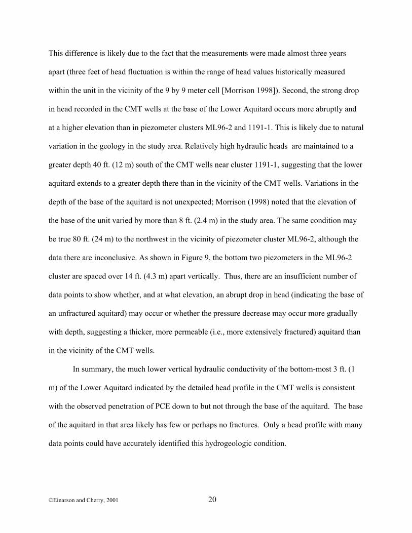
This difference is likely due to the fact that the measurements were made almost three years
apart (three feet of head fluctuation is within the range of head values historically measured
within the unit in the vicinity of the 9 by 9 meter cell [Morrison 1998]). Second, the strong drop
in head recorded in the CMT wells at the base of the Lower Aquitard occurs more abruptly and
at a higher elevation than in piezometer clusters ML96-2 and 1191-1. This is likely due to natural
variation in the geology in the study area. Relatively high hydraulic heads are maintained to a
greater depth 40 ft. (12 m) south of the CMT wells near cluster 1191-1, suggesting that the lower
aquitard extends to a greater depth there than in the vicinity of the CMT wells. Variations in the
depth of the base of the aquitard is not unexpected; Morrison (1998) noted that the elevation of
the base of the unit varied by more than 8 ft. (2.4 m) in the study area. The same condition may
be true 80 ft. (24 m) to the northwest in the vicinity of piezometer cluster ML96-2, although the
data there are inconclusive. As shown in Figure 9, the bottom two piezometers in the ML96-2
cluster are spaced over 14 ft. (4.3 m) apart vertically. Thus, there are an insufficient number of
data points to show whether, and at what elevation, an abrupt drop in head (indicating the base of
an unfractured aquitard) may occur or whether the pressure decrease may occur more gradually
with depth, suggesting a thicker, more permeable (i.e., more extensively fractured) aquitard than
in the vicinity of the CMT wells.
In summary, the much lower vertical hydraulic conductivity of the bottom-most 3 ft. (1
m) of the Lower Aquitard indicated by the detailed head profile in the CMT wells is consistent
with the observed penetration of PCE down to but not through the base of the aquitard. The base
of the aquitard in that area likely has few or perhaps no fractures. Only a head profile with many
data points could have accurately identified this hydrogeologic condition.
©Einarson and Cherry, 2001 20
In June 1998, head measurements were again made in CMT wells ME-1 and ME-2. This
time, however, the measured heads in well ME-2 were much different than the earlier
measurements, suggesting that one or more of the lower seals had likely failed. The potential
causes of the leakage could have been due to one or more of the following: (1) a poor bond
between the polyethylene sealant and the tubing caused by insufficient heating of the sealant; (2)
deformation of the bentonite packers en route to the job site from the warehouse where the wells
constructed; and/or (3) slow dissolution of the bentonite packers when they are not completely
surrounded by a porous medium (as may be the case in installations in boreholes drilled into
aquitards or bedrock where the tops and bottoms of the packers contact only water in the
borehole) (Einarson 2001). Additional field testing of the bentonite packers is planned to
determine which of these factors likely caused the packer failure at the Borden site.
Santa Monica, California
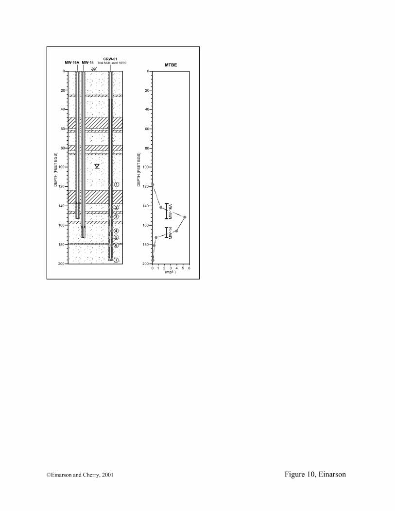
A trial multi-level well was installed in Santa Monica, California in December 1999 to
assess the feasibility of using CMT multi-level wells to monitor a dissolved plume of methyl tert
butyl ether (MTBE) located more than 120 ft. (37 m) below the ground surface. The trial well
was located within 20 ft. (6 m) of a pair of 4-in. (10-cm) diameter conventional monitoring wells
in order to compare the concentrations of MTBE in water samples collected from the CMT well
with samples collected from the conventional wells. Continuous soil cores were first collected
with a sonic drilling rig to a depth of 195 ft. (60 m). 3.5-in. (9-cm) I.D. flush-threaded steel
casing was advanced incrementally to keep the borehole open. The cores were logged in detail
to identify preferred pathways of contaminant migration. The well was built completely above
ground and inserted into the borehole prior to removing the steel casing. The well was
developed (using the gas lift/vacuum extraction method described earlier) and samples were
©Einarson and Cherry, 2001 21
collected at a rate of 120 mL/min using a 0.25-in. (0.64-cm) O.D. Teflon inertial lift pump
manufactured by Solinst Canada, Ltd.
A summary of the stratigraphy and construction of the CMT well and the nearby
conventional monitoring wells is shown in Figure 10. A graph of MTBE concentrations versus
depth for all three wells is shown on the right of the figure. Comparison of the MTBE
concentrations measured in samples from the CMT well with data from the conventional wells
provides an example of contaminant mixing in monitoring wells described earlier. It is clear
from the figure that wells MW-14 and MW-16 yield ground water samples that are a composite
of ground water within the vertical interval of the aquifer screened by the wells. Analysis of a
sample from Zone 3 of the CMT well shows that MTBE is present in the aquifer at
concentrations as high as 5,300 µg/L. However, the concentration of MTBE measured in
samples from the conventional wells is much lower (approximately 2,300 µg/L) because
relatively clean water (entering the upper portion of MW-16’s well screens and the lower portion
of MW-14’s well screens) mixes with the water containing high concentrations of MTBE when
these wells are pumped.
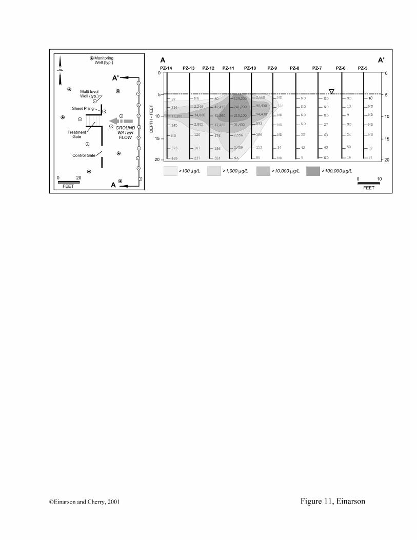
Alameda Point, California
A transect of 10 CMT multi-level monitoring wells was installed at Site 1, Alameda Point
(formerly Alameda Naval Air Station), California, during the course of a three-year University of
Waterloo field experiment to treat a mixed plume of VOCs and petroleum hydrocarbons in situ
using a sequential reactive barrier (Morkin et al. 1998; Fiorenza et al. 2000).
Because the aquifer consists of loose unconsolidated sand, the multi-level wells could be
installed by simply inserting the CMT tubing and well screens into small-diameter steel drive
casing that had been vibrated with a knock-out plug to the bottom of the aquifer (22 ft. [6.7 m]
©Einarson and Cherry, 2001 22
bgs). After each multi-level well was inserted, the drive casing was removed, allowing the
native sand to collapse around the drive casing.
Figure 11 shows concentration contours of cis-1,2 DCE along the transect of monitoring
wells collected in December 1998. A high-strength plume core, exhibiting concentrations of cis-
1,2 DCE greater than 300,000 µg/L, was mapped in the upper portion of the aquifer in the
vicinity of well PZ-11. The plume core is surrounded by ground water having as much as three
orders of magnitude lower concentrations of dissolved VOCs. The large variation in
concentrations of dissolved VOCs in a single multi-level well over vertical distances of just a
few feet provides evidence that there is no enhanced hydraulic interconnection between the
intake ports.
The Alameda Point VOC plume provided an opportunity to test the hypothesis that
sampling biases could be minimized by thoroughly purging the various channels prior to
sampling and collecting ground water samples from separate Teflon sampling tubing inserted to
the bottom of each CMT channel. These techniques were followed when collecting all of the
samples from the multi-level wells at Alameda Point. In addition, one well (PZ-14D, located
next to well PZ-14) was constructed with separate stainless steel “control” sampling tubing to
further assess potential sampling biases associated with the new CMT monitoring system.
Stainless steel is much less affected by sorption/desorption of organic compounds than polymeric
tubing. Therefore, it was thought that samples collected from the stainless steel tubing would
yield independent values of dissolved solute concentrations in the aquifer that were not biased by
processes affecting the polymeric tubing. When constructing well PZ-14D, 0.13-in. (3.3-mm)
O.D. stainless steel tubing was secured to the outside of the multi-channel tubing. Seven lengths
of tubing were attached, each one extending to the depth of one of the ports of the multi-level
©Einarson and Cherry, 2001 23
monitoring well. The ends of the stainless steel tubing were wrapped in a fine stainless steel
mesh, allowing for the independent collection of ground water samples from the aquifer at the
same depths as the ports in the CMT multi-level well.
Well PZ-14D Sampling Technique
Ground water samples were collected from the Teflon sampling tubing and the stainless
steel control tubing using a peristaltic pump. To minimize potential sampling biases caused by
stagnant water in the various CMT channels, a dual-tube water sampling technique was
employed. In addition to the sampling tubing described above, separate lengths of 0.25-in.
(0.64-cm) O.D. polyethylene “purge tubing” were inserted into each CMT channel three ft. (0.9
m) below the static ground water depth (i.e., to a depth of approximately 8 ft. [2.4 m] bgs).
Water was then simultaneously pumped from the shallow purge tubing and the deeper sampling
tubing (either the Teflon or stainless steel tubing) in each channel using a dual-head peristaltic
pump (Figure 12). By doing this, stagnant water above the CMT intake ports was drawn
upwards, away from the intake of the Teflon or stainless steel sampling tubing. Ground water
entering the CMT sampling ports was immediately drawn into the deeper sampling tubing, thus
minimizing contact with the HDPE CMT tubing.
Samples of the stagnant water in the various channels were collected from the first 40 mL
of water pumped from the upper purge tubing. This was done to test the hypothesis that VOCs
present at shallow depths in the aquifer may have diffused into channels monitoring deeper zones
during the eight-month period since the wells were last sampled. Ground water samples were
then collected from each length of the stainless steel control tubing and the 0.25 in. (0.64 cm)
Teflon sampling tubing after approximately 750 mL of water had been purged and electrical
conductivity (EC) measurements had stabilized. Samples were collected in 40 mL glass vials
©Einarson and Cherry, 2001 24
positioned upstream of the peristaltic pump. All samples were spiked with sodium azide to
minimize aerobic biodegradation of the organic compounds and were shipped on ice to the
University of Waterloo analytical laboratory in Ontario, Canada.
Analytical Method
All VOCs were analyzed at University of Waterloo’s analytical laboratory by the
headspace technique using a Varian Genesis autosampler and a Hewlett Packard 5890 gas
chromatograph equipped with a split injection port 12:1 at 150° C, and a capillary column DB-
VRX 30 m x 0.32 mm I.D., maintained isothermally at 32°C. Helium was used as the carrier gas
at a flow rate of 3.5 mL/min, and a photoionization detector (PID) was used with a 11.7 eV lamp.
A complete list of analytes and associated method reporting limits is presented by Einarson
(2001).
Results
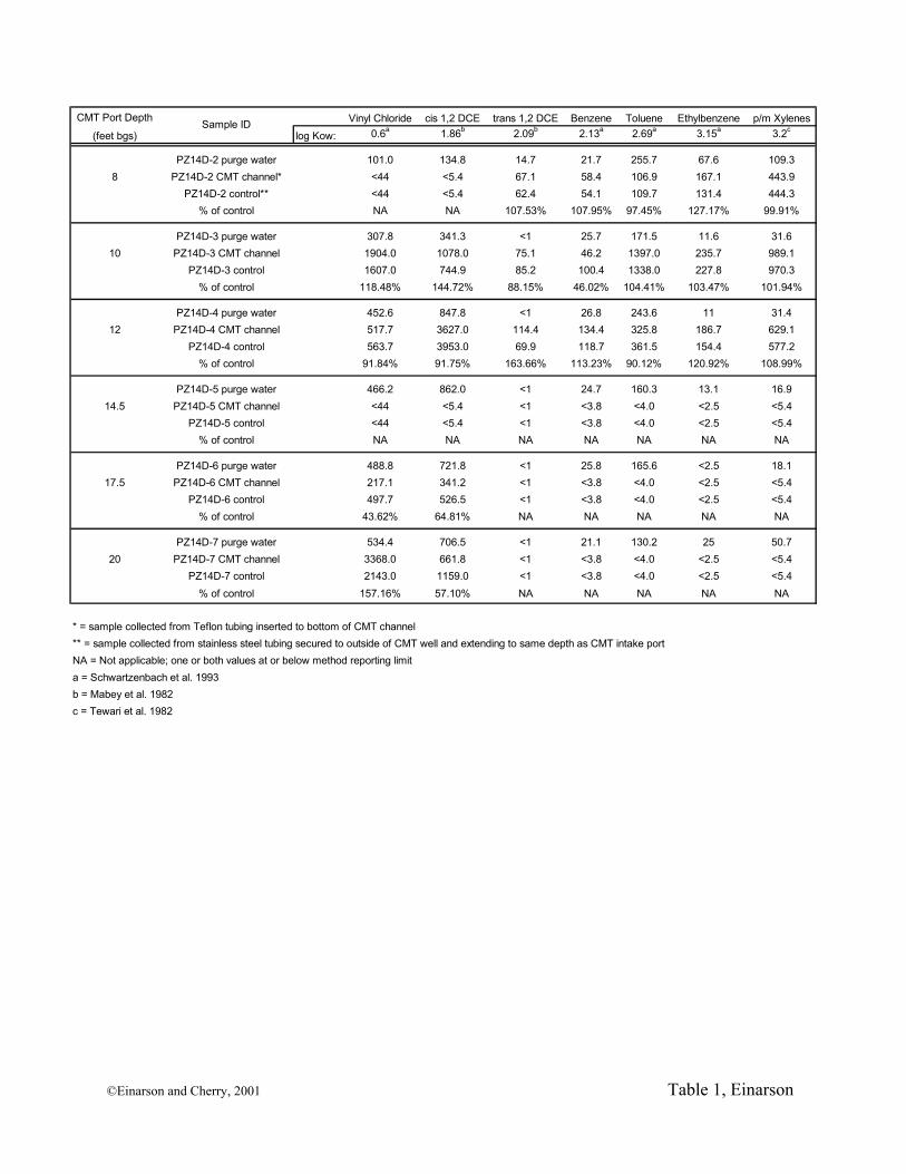
Table 1 presents a summary of analytical results for VOCs in samples collected from
multi-level well PZ-14D in June 1999. Octanol-water partition coefficients (Kow) are also listed
for each compound shown. Compounds with higher Kow values are more hydrophobic and
would be expected to diffuse more rapidly through the walls of the CMT tubing as discussed
above. Those compounds could also preferentially sorb to the inside walls of the CMT tubing,
resulting in a potential negative bias.
As shown in Table 1, many VOCs were detected in samples of purge water from
channels monitoring deeper portions of the aquifer (i.e., below the high-strength core of the VOC
plume) but were not detected in samples collected from the corresponding stainless steel or
Teflon sampling tubing after purging was complete. This indicates that VOCs detected in the
purge water from those channels likely resulted from diffusion of VOCs from adjacent channels
©Einarson and Cherry, 2001 25
or from the contaminant plume directly. This positive bias was effectively removed by purging
the stagnant water from the channels prior to sampling and collecting the samples from separate
sampling tubing inserted to the full depth of the various CMT channels.
No aromatic hydrocarbons were detected in samples collected from either the stainless
steel or Teflon sampling tubing below a depth of 12 ft. (3.7 m). Cis-1,2 DCE and vinyl chloride,
however, were detected in the Teflon and stainless steel tubing near the bottom of the aquifer
(i.e., the channels monitoring ground water at depths of 17.5 and 20 ft. [5.4 and 6.1 m] bgs). The
fact that these compounds were detected in samples collected from the Teflon sampling tubing at
concentrations higher than those measured in samples of the purge water suggests that the VOCs
are present near the base of the aquifer, beneath the core of the VOC plume, and are not artifacts
of diffusion through the CMT tubing. Measurement of high concentrations of cis-1,2 DCE and
vinyl chloride in samples from the stainless steel control tubing at the same depths supports that
conclusion.
Overall, there is a reasonably good match between the concentrations of VOCs measured
in most of the samples collected from the CMT channels and the stainless steel control tubing.
In some cases, concentrations of VOCs were higher in samples collected from the stainless steel
control tubing than the samples collected from the CMT channels (e.g., cis-1,2 DCE measured in
samples from depths of 17.5 and 20 ft. [5.4 and 6.1 m]). This may be evidence of a negative
sampling bias caused by inadequate flushing of water through the Teflon sampling tubing prior
to sample collection. As discussed above, sorption of hydrophobic solutes onto virgin Teflon
sampling tubing can decrease the concentration of organic solutes in the samples initially
collected from the tubing. In several instances, the concentrations of VOCs were higher in the
samples collected from the Teflon sampling tubing than the samples from the stainless steel
©Einarson and Cherry, 2001 26
control tubing. This may be evidence of a negative bias in samples collected from the stainless
steel control tubing due to degassing during sample collection. The tips of the stainless steel
control tubing are wrapped with a very fine stainless steel mesh to prevent sand from clogging
the ends of the tubing. The fine mesh likely causes a significant head loss due to friction when
the stainless steel tubing was being pumped. Thus, a larger vacuum was applied to collect
ground water samples from the stainless steel control tubing than the larger CMT channels.
Alternatively, the differences between solute samples collected from the CMT channels (i.e., the
Teflon sampling tubing) and the stainless steel “control” tubing could be primarily a result of
micro-scale variations in the distribution of dissolved contaminants surrounding the multi-level
monitoring well. As discussed above, the aquifer near well PZ-14D exhibits striking variability
in the concentration and spatial distribution of dissolved VOCs. In fact, DNAPL was sampled in
a CMT multi-level well 30 ft. (9 m) away from well PZ-14D during a later sampling event.
Therefore, because of the documented variability in the actual concentration of the various
solutes in the aquifer surrounding well PZ-14D, the designation of samples from the stainless
steel tubing as “control” samples should be viewed with caution. Similar testing and comparisons
performed in a laboratory setting would likely provide a more rigorous evaluation of the
potential biases associated with the various methods of sampling CMT multi-level monitoring
wells.
Cost To gain widespread use, installations of multi-level monitoring systems must be less
expensive than other methods for permanent depth-discrete ground water monitoring, e.g.,
clusters of conventional monitoring wells. The price of the CMT well materials is comparable to
the materials used to construct conventional monitoring wells: The current price for the CMT
©Einarson and Cherry, 2001 27
tubing ranges from $US 3.95 to $6.50 per linear foot. (depending on volume purchased [Solinst
Canada, Ltd. 2001]), a cost similar to 2-in. (5-cm) or 4-in. (10-cm) diameter slotted PVC pipe.
Aside from the CMT tubing, all of the other components are off-the-shelf materials commonly
used in environmental investigations (e.g., stainless steel mesh, sand, bentonite pellets, etc.).
The real cost savings, of course, are apparent when the cost of drilling and installing one
CMT well is compared to the cost of drilling and installing seven individual monitoring wells.
Drilling footage, well materials, and disposal of investigation-derived waste (i.e., drill cuttings)
is reduced seven fold. More time is needed to construct a seven-zone CMT well than a
conventional single-zone monitoring well; however, experience shows that building a CMT well
using either conventional (tremie) methods or with seals made of bentonite packers takes about
twice the time as constructing a conventional monitoring well to the same depth.
Conclusions The CMT multi-level monitoring system represents a new low-cost multi-level
monitoring system that can be installed with a variety of drilling equipment to depths currently
greater than 250 ft. (76 m). Continuous multi-channel HDPE tubing eliminates the potential for
leakage at joints (since there are no joints), and contributes to the low cost of the system.
Compared to nested monitoring wells, having only one tube in a borehole simplifies the
installation of sand packs and annular seals, which can be installed from the surface using
conventional tremie methods. Bentonite packers and pre-packed sand packs have also been
developed that are attached to the tubing at the ground surface. Fully-built multi-level wells are
then inserted into boreholes in overburden through steel drive casing or in open holes in bedrock
in just a few minutes. Above-ground construction is feasible because the CMT tubing is flexible
enough to be lowered “hand-over-hand” into a borehole. Above-ground construction ensures
©Einarson and Cherry, 2001 28
that the sand packs and seals are located at precisely the desired depths, a goal that is sometimes
not met when sand and bentonite tablets are poured from the surface or via a tremie pipe.
Additional field testing and monitoring of the bentonite packer seals is needed, however, to
assess the long-term viability of the seals in a variety of hydrogeologic settings.
Like all ground water monitoring devices, there are biases inherent with the CMT multi-
level system. The design of the system requires that the tubing be flexible so that it can be
inserted hand-over-hand into a borehole. There are several types of flexible polymeric tubing,
but HDPE was selected as the optimum material because of its favorable working characteristics
and low cost. For many target contaminants, HDPE is susceptible to both positive and negative
biases caused by sorption, desorption, and diffusion. These biases can be minimized by (1)
purging the channels prior to sampling and (2) collecting samples from separate 0.25-in. (0.64-
cm) diameter Teflon sampling tubing or canister samplers placed to the bottom of each sampling
channel adjacent to the various ports. In this way ground water samples are collected that have
minimal contact with the HDPE CMT tubing. Evaluations of the CMT system performed to
date have focused on VOCs, but it is expected that with appropriate sampling methods, the
system can be used to collect viable samples of ground water containing other dissolved
contaminants. Also, additional evaluations of other sampling methods and pumps should be
undertaken, ideally in a laboratory setting. Additional studies should include evaluations of
small-diameter canister samplers and other types of small-diameter pumps that are currently
being developed for the system.
©Einarson and Cherry, 2001 29
Acknowledgments
Funding for the development and testing of the CMT system was provided by (1) Precision Sampling, Inc., Richmond, California, (2) Conor Pacific/EFW, Palo Alto, California, (3) the University Consortium Solvents-In-Groundwater Research Program, and (4) Solinst Canada, Ltd. Solinst Canada, Ltd. is the exclusive licensee of the CMT system. The authors are grateful to the U.S Navy, U.S. Air Force, the Charnock Regional Assessment Group, and Defence Canada for providing sites to test the CMT technology. The authors would also like to thank Doug Mackay, Jim Barker, Rick Devlin, Don Winglewich, Rob Dobush, Gary Soden (Clear Heart Drilling), Bob Ingleton, and Paul Johnson for their technical assistance and support, Resonant Sonic International for their considerable in-kind support, and Denise Mason and Kate Motroni for their technical graphics. Finally, we thank James Martin-Hayden and two anonymous reviewers for their thoughtful comments that greatly improved the quality of this article.
References
Barcelona, M.J., J.A. Helfrich, and E.E. Garske. 1985. Sampling tubing effects on ground water samples. Analytical Chemistry 57: 460-464.
Barker, J.F., G.C. Patrick, L. Lemon, and G.M. Travis. 1987. Some bases in sampling multilevel piezometers for volatile organics. Ground Water Monitoring Review 7, no. 2: 48-54.
Barrow, J.C. 1994. The resonant sonic drilling method: An innovative technology for environmental restoration programs. Ground Water Monitoring and Remediation 14, no. 2: 153-160.
Black, W.H. and F.D. Patton. 1986. Multiple-level ground water monitoring with the MP system. Paper presented at Surface and Borehole Geophysical Methods and Ground Water Instrumentation Conference and Exposition, October 15-17, 1986, in Denver, Colorado. National Water Well Association.
Brewster, M.L., A.P. Annan, J.P. Greenhouse, B.H. Kueper, G.R. Olhoeft, and J.D. Redman. 1995. Observed migration of a controlled DNAPL release by geophysical methods. Ground Water 33, no. 6: 977-987.
Butler, J.J. 2001. University of Kansas Geological Survey. Pers. Comm. Cherry, J.A., R.W. Gillham, E.G. Anderson, and P.E. Johnson. 1983. Migration of contaminants in groundwater at a
landfill: A case study. 2. Groundwater monitoring devices. Journal of Hydrology 63: 31-49. Cherry, J.A. and P.E. Johnson. 1982. A multilevel device for monitoring in fractured rock. Ground Water
Monitoring Review 2, no. 3: 41-44. Curran, C.M. and M.D. Tomson. 1983. Leaching of trace organics into water from five common plastics. Ground
Water Monitoring Review 3, no. 3: 68-71. Einarson, M.D. 1995. EnviroCore: A new dual-tube direct push system for collecting continuous soil cores. Paper
presented at 9th National Outdoor Action Conference, May 8 - 12, 1995, in Las Vegas, Nevada. National Ground Water Association.
Einarson, M.D. 2001. A new, low-cost multi-level monitoring system. M.Sc. thesis. Department of Earth Sciences, University of Waterloo, Waterloo, Ontario Canada. 89 pp.
Fiorenza, S., C.L. Oubre, and C.H. Ward. 2000. Sequenced reactive barriers for groundwater remediation. Boca Raton: Lewis Publishers.
Foley, S. 1992. Influence of sand microbeds on hydraulic response of an unconfined clay aquitard. M.Sc. thesis. Department of Earth Sciences, University of Waterloo, Waterloo, Ontario Canada. 277 pp.
Garabedian, S.P., D.R. LeBlanc, L.W. Gelhar, and M.A. Celia. 1991. Large-scale natural gradient tracer test in sand and gravel, Cape Cod, Massachusetts. II. Analysis of spatial moments for a nonreactive tracer. Water Resources Research 27, no. 5: 911-924.
Gillham, R.W. 1989. Selection of casing materials for groundwater monitoring wells -- sorption processes. Paper presented at NSWMA Waste Tech 1989, October 23, 1989, in Washington, D.C. National Solid Waste Management Association.
©Einarson and Cherry, 2001 30
Gillham,R.W. and S.F.O'Hannesin. 1990. Sorption of aromatic hydrocarbons by materials used in construction of monitoring wells. In Ground Water and Vadose Zone Monitoring, ASTM STP 1053, Philadelphia: American Society for Testing and Materials.
Hewitt, A.D. 1992. Potential of common well casing materials to influence aqueous metal concentrations. Ground Water Monitoring Review 12, no. 2: 131-136.
Hewitt, A.D. 1994. Dynamic study of common well screen materials. Ground Water Monitoring and Remediation 14, no. 1: 87-94.
Johnson, R.L., J.F. Pankow, and J.A. Cherry. 1987. Design of a ground-water sampler for collecting volatile organics and dissolved gases in small-diameter wells. Ground Water 25, no. 4: 448-454.
Junk, G.A., H.J. Svec, R.D. Vick, and M.J. Avery. 1974. Contamination of water by synthetic polymer tubes. Environmental Science & Technology 8, no. 11: 1100-1106.
LeBlanc, D.R., S.P. Garabedian, K.M. Hess, L.W. Gelhar, R.D. Quadri, K.G. Stollenwerk, and W.W. Wood. 1994. Large-scale natural gradient tracer test in sand and gravel, Cape Cod, Massachusetts. I. Experimental design and observed tracer movement. Water Resources Research 27, no. 3: 893-910.
Mackay, D.M., W.P. Ball, and M.G. Durant. 1986a. Variability of aquifer sorption properties in a field experiment on groundwater transport of organic solutes: Methods and preliminary results. Journal of Contaminant Hydrology 1 (1986): 119-132.
Mackay, D.M., J.A. Cherry, D.L. Freyberg, and P.V. Roberts. 1986b. A natural gradient experiment on solute transport in a sand aquifer 1. Approach and overview of plume movement. Water Resources Research 22, no. 13: 2017-2029.
Martin-Hayden, J.M., G.A. Robbins, and R.D. Bristol. 1991. Mass balance evaluation of monitoring well purging, Part II, Field tests at a gasoline contamination site. Journal of Contaminant Hydrology 8: 225-241.
Meldrum, C.I. 1999. Use of a new multi-level monitoring system for determining hydraulic head distribution in the Borden Aquitard. B.Sc. thesis. Department of Earth Sciences, University of Waterloo, Waterloo Ontario. 45 pp.
Morkin, M.I., J.F. Barker, J.F. Devlin, and M. McMaster. 1998. In-situ sequential treatment of a mixed organic plume using granular iron, O2, and CO2 sparging. Paper presented at First International Conference on Remediation of Chlorinated and Recalcitrant Compounds, May 18 to 21, 1998, in Monterey, California. Battelle Press.
Morrison, W.E. 1998. Hydrogeologic controls on flow and fate of PCE DNAPL in a fractured and layered clayey aquitard: A Borden experiment. M.Sc. thesis. Department of Earth Sciences, University of Waterloo, Waterloo, Ontario. 355 pp.
Pankow, J.F., L.M. Isabelle, J.P. Hewetson, and J.A. Cherry. 1985. A tube and cartridge method for down-hole sampling for trace organics in ground water. Ground Water 23: 775.
Parker, L.V. 1994. The effects of ground water sampling devices on water quality: A literature review. Ground Water Monitoring and Remediation 14, no. 2: 130-141.
Parker, L.V., A.D. Hewitt, and T.F. Jenkins. 1990. Influence of casing materials on trace-level chemicals in well water. Ground Water Monitoring Review 10, no. 2: 146-156.
Parker, L.V. and T.A. Ranney. 1997. Sampling trace-level organic solutes with polymeric tubing. Part I. Static studies. Ground Water Monitoring and Remediation 17, no. 4: 115-124.
Parker, L.V. and T.A. Ranney. 1998. Sampling trace-level organic solutes with polymeric tubing. Part 2. Dynamic studies. Ground Water Monitoring and Remediation 18, no. 1: 148-155.
Pickens, J.F., J.A. Cherry, G.E. Grisak, W.F. Merritt, and B.A. Risto. 1978. A multilevel device for groundwater sampling and piezometric monitoring. Ground Water 16, no. 5: 322-327.
Ranney, T.A. and L.V. Parker. 1998. Comparison of fiberglass and other polymeric well casings, Part III. Sorption and leaching of trace-level metals. Ground Water Monitoring and Remediation 18, no. 3: 127-133.
Rannie, E.H. and R.L. Nadon. 1985. An inexpensive, multi-use, dedicated pump for ground water monitoring wells. Ground Water Monitoring Review 8, no. 4: 100-107.
Reinhard, M., N.L. Goodman, and J.F. Barker. 1984. Occurrence and distribution of organic chemicals in two landfill leachate plumes. Environmental Science & Technology 18: 953-961.
Robbins, G.A. 1989. Influence of purged and partially penetrating monitoring wells on contaminant detection, mapping, and modeling. Ground Water 27, no. 2: 155-162.
Robbins, G.A. and J.M. Martin-Hayden. 1991. Mass balance evaluation of monitoring well purging, Part I, Theoretical models and implications for representative sampling. Journal of Contaminant Hydrology 8: 203-224.
©Einarson and Cherry, 2001 31
Robertson, W.D., J.A. Cherry, and E.A. Sudicky. 1991. Ground water contamination from two small septic systems on sand aquifers. Ground Water 29, no. 1: 82-92.
Schwartzenbach, R.P., P.M. Gschwend, and D.M. Imboden. 1993. Environmental Organic Chemistry. New York: John Wiley & Sons, Inc. 681 pp
Solinst Canada, Ltd. 2001. pers. comm. www.solinst.com. Tewari, Y.B., M.M. Miller, S.P. Wasik, and D.E. Martine. 1982. Aqueous solubility and octanol-water partition
coefficient of organic compounds at 25 degrees C. Journal of Chemical Engineering Data 27: 451-154. US EPA. 1986. RCRA ground-water monitoring technical enforcement guidance document. Office of Waste
Programs Enforcement, Office of Solid Waste and Emergency Response, Washington D.C. OSWER-9950.1. 317 pp.
van der Kamp, G., L.D. Luba, J.A. Cherry, and H. Maathuis. 1994. Field study of a long and very narrow contaminant plume. Ground Water 32, no. 6: 1008-1016.
©Einarson and Cherry, 2001 32
Table Title and Figure Captions
A New Multi-Level Ground Water Monitoring System
Utilizing Multi-Channel Tubing
Einarson & Cherry, 2001
Table
Table 1. Concentrations of Select VOCs and Petroleum Hydrocarbons in Samples Collected from CMT Well PZ-14D, June 7, 1999, Alameda Point, California. (All concentrations in µg/L)
Figures
Figure 1. CMT tubing.
Figure 2. CMT tubing coil.
Figure 3. Typical CMT intake port.
Figure 4. Installation of a CMT multi-level well where sand pack and bentonite seals are tremied from the ground surface.
Figure 5. Installation of the CMT well with pre-packed sand packs and bentonite packers.
Figure 6. Stainless steel form used to construct bentonite packers.
Figure 7. Bentonite packer (right) prior to insertion in a borehole. To left, bentonite packer after it has hydrated and swelled.
Figure 8. Inserting a CMT multi-level well equipped with bentonite packers and pre-packed sand packs.
Figure 9. Generalized stratigraphy, well construction, and hydraulic head profile. CMT multilevel wells ME-1 and ME-2, Canadian Forces Base Borden, Ontario, Canada.
Figure 10. Construction details and MTBE concentration profile from a trial CMT multi-level well plotted next to data from two nearby conventional monitoring wells. Santa Monica, California.
Figure 11. A stratified VOC plume at Alameda Point, California. Site plan shown on left. On right, transect A to A” (perpendicular to the direction of ground water flow) showing concentration contours of cis-1,2 DCE across the dissolved plume. Figure 12. Dual-tube ground water sampling apparatus.
©Einarson and Cherry, 2001
©Einarson and Cherry, 2001 Table 1, Einarson
CMT Port Depth Vinyl Chloride cis 1,2 DCE trans 1,2 DCE Benzene Toluene Ethylbenzene p/m Xylenes(feet bgs) log Kow: 0.6a 1.86b 2.09b 2.13a 2.69a 3.15a 3.2c
PZ14D-2 purge water 101.0 134.8 14.7 21.7 255.7 67.6 109.38 PZ14D-2 CMT channel* <44 <5.4 67.1 58.4 106.9 167.1 443.9
PZ14D-2 control** <44 <5.4 62.4 54.1 109.7 131.4 444.3% of control NA NA 107.53% 107.95% 97.45% 127.17% 99.91%
PZ14D-3 purge water 307.8 341.3 <1 25.7 171.5 11.6 31.610 PZ14D-3 CMT channel 1904.0 1078.0 75.1 46.2 1397.0 235.7 989.1
PZ14D-3 control 1607.0 744.9 85.2 100.4 1338.0 227.8 970.3% of control 118.48% 144.72% 88.15% 46.02% 104.41% 103.47% 101.94%
PZ14D-4 purge water 452.6 847.8 <1 26.8 243.6 11 31.412 PZ14D-4 CMT channel 517.7 3627.0 114.4 134.4 325.8 186.7 629.1
PZ14D-4 control 563.7 3953.0 69.9 118.7 361.5 154.4 577.2% of control 91.84% 91.75% 163.66% 113.23% 90.12% 120.92% 108.99%
PZ14D-5 purge water 466.2 862.0 <1 24.7 160.3 13.1 16.914.5 PZ14D-5 CMT channel <44 <5.4 <1 <3.8 <4.0 <2.5 <5.4
PZ14D-5 control <44 <5.4 <1 <3.8 <4.0 <2.5 <5.4% of control NA NA NA NA NA NA NA
PZ14D-6 purge water 488.8 721.8 <1 25.8 165.6 <2.5 18.117.5 PZ14D-6 CMT channel 217.1 341.2 <1 <3.8 <4.0 <2.5 <5.4
PZ14D-6 control 497.7 526.5 <1 <3.8 <4.0 <2.5 <5.4% of control 43.62% 64.81% NA NA NA NA NA
PZ14D-7 purge water 534.4 706.5 <1 21.1 130.2 25 50.720 PZ14D-7 CMT channel 3368.0 661.8 <1 <3.8 <4.0 <2.5 <5.4
PZ14D-7 control 2143.0 1159.0 <1 <3.8 <4.0 <2.5 <5.4% of control 157.16% 57.10% NA NA NA NA NA
* = sample collected from Teflon tubing inserted to bottom of CMT channel** = sample collected from stainless steel tubing secured to outside of CMT well and extending to same depth as CMT intake port NA = Not applicable; one or both values at or below method reporting limita = Schwartzenbach et al. 1993b = Mabey et al. 1982c = Tewari et al. 1982
Sample ID
©Einarson and Cherry, 2001 Figure 1, Einarson
©Einarson and Cherry, 2001 Figure 2, Einarson
©Einarson and Cherry, 2001 Figure 3, Einarson
typ.) 0.38-inch hole drilled into only one channel.
Holes covered by stainless steel mesh.
Hole to injectpolyethylene
sealant
Polyethylene plug inside channel
7-channel HDPE tubing
Stainless steel mesh
0.38-inch holes drilled into
channel #3 (typ.)
Polyethylene sealant injected below
intake forming plug
5 6 1
234
7
Sealant plug in all channels except
central one (Zone 7)
Stainless steel screen cap (Zone
7 only)
Vent holeZone 4 intake
Zone 5 intake
Zone 6 intake
Zone 7 intake
Zone 3 intake
Zone 2 intake
PVC wellcentralizer (typ.)
Zone 1 intake
CMT tubing
NOT TO SCALE
©Einarson and Cherry, 2001 Figure 4, Einarson
After hydration of bentonite packers.
CMTtubing
Sand Pack (typ.)
Centralizer (typ.)
Bentonite within polyethylenenetting (typ.)
Zone 2 Intake
Zone 3 Intake
Zone 4 Intake
Before hydration of bentonite packers.
Zone 5 Intake
Zone 6 Intake
Zone 7 Intake
Zone 1 Intake
Stainless steel mesh
Polypropylene mesh
0.38-inch holes drilled into channel
#3 (typ.) Polyethylene
sealant injected below intake forming plug
Sand
Vent hole
3 2
165
4
77-channel HDPE tubing
Sealant plug in all channels except
central one (Zone 7)
Stainless steel screen cap
(Zone 7 only)
0.25-inch bentonite pellets within
polyethylene netting
Stainless steel clamp
(typ.)
NOT TO SCALE
©Einarson and Cherry, 2001 Figure 5, Einarson
©Einarson and Cherry, 2001 Figure 6, Einarson
©Einarson and Cherry, 2001 Figure 7, Einarson
©Einarson and Cherry, 2001 Figure 8, Einarson
©Einarson and Cherry, 2001 Figure 9, Einarson
Hydraulic HeadProfile
ME-1 ME-2
UPPERAQUIFER
LOWER AQUITARD
70 5
69 5
68 5
67 5
6 9 0 7 0 0 7 2 07 1 0
HYDRAULIC HEAD(FEET ASL)EXPLANATION
Head measured in CMT wells ME-1 & ME-2 on 1/19/99 (Meldrum 1999)
Head measured in piezometer cluster ML96-2 on 11/18/96 (Morrison 1998)
Head measured in piezometer cluster 1191-1 on 12/20/96 (Morrison 1998)
Generalized Stratigraphy and CMT Well Construction
? ? ?
5
6
1
2
3
7
45
6
1
2
3
4
567
LOWER AQUIFER
Approximate contact between upper fractured aquitard and lower unfractured aquitard
?
ELEV
. (FE
ET A
SL)
70 5
69 5
68 5
67 5
UPPERAQUITARD
DEP
TH (F
EET
BG
S)
0
20
40
60
MW-16A MW-14
80
100
120
140
160
180
200
1
2
3
5
6
7
MTBE
(mg/L)0 1 2 3 4 5 6
MW
-16A
MW
-14
CRW-01Trial Multi-level 10/99
DEP
TH (F
EET
BG
S)
0
20
40
60
80
100
120
140
160
180
200
4
©Einarson and Cherry, 2001 Figure 10, Einarson
N
GROUNDWATERFLOW
FEET
200
A
A'
TreatmentGate
Sheet Piling
Control Gate
Multi-levelWell (typ.)
MonitoringWell (typ.)
>100,000 µg/L>100 µg/L
DEP
TH -
FEET
FEET
100
0
20
15
10
5
0
20
15
10
5
>1,000 µg/L >10,000 µg/L
10
ND
ND
ND
ND
32
31ND
43
63
27
ND
ND
ND
8
42
25
34
85
153
186
593
94,430
96,430
2,560
NA
2,409
2,556
31,430
210,100
241,700
129,200
324
156
476
17,280
61,980
42,490
80
237
107
120
2,805
34,860
2,246
NA
469
573
ND
145
11,100
294
37 ND
ND
ND
376
ND
ND
ND
ND
ND
ND
16
50
24
ND
9
13
ND
A A'PZ-5PZ-6PZ-7PZ-8PZ-9PZ-10PZ-11PZ-12PZ-13PZ-14
©Einarson and Cherry, 2001 Figure 11, Einarson
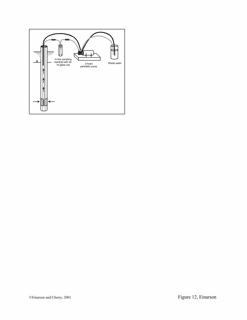
In-line sampling manifold with 40-
ml glass vial 2-head peristaltic pump
Waste water
©Einarson and Cherry, 2001 Figure 12, Einarson