Embed Size (px)
Citation preview

European Congress on Computational Methodsin Applied Sciences and Engineering (ECCOMAS 2012)
J. Eberhardsteiner et.al. (eds.)Vienna, Austria, September 10-14, 2012
A NEW PROCEDURE TO SMOOTH AND UNTANGLE MESHES ONPARAMETERIZED SURFACES
Abel Gargallo-Peiro1, Xevi Roca2, Josep Sarrate1
1Laboratori de Calcul Numeric (LaCaN),Universitat Politecnica de Catalunya, Barcelona 08034, Spain
{abel.gargallo,jose.sarrate}@upc.edu
2Department of Aeronautics and AstronauticsMassachusetts Institute of Technology, Cambridge, MA 02139, USA
{xeviroca}@mit.edu
Keywords: mesh quality, mesh optimization, smoothing and untangling, CAD surfaces
Abstract. We present a technique to extend any distortion (quality) measure for planar meshesto meshes on parameterized surfaces. The resulting distortion (quality) measure is expressed interms of the parametric coordinates of the nodes. This extended distortion (quality) measure canbe used to check the quality and validity of both triangle and quadrilateral surface meshes. Wealso apply it to simultaneously smooth and untangle surface meshes by minimizing the extendeddistortion measure. The minimization is performed in terms of the parametric coordinates of thenodes and therefore, the nodes always lie on the surface. Finally, we include several examples toillustrate the applicability of the proposed technique. Specifically, we extend several Jacobian-based measures, and we us them to smooth and untangle triangle and quadrilateral meshes onCAD surfaces.

Abel Gargallo-Peiro, Xevi Roca, and Josep Sarrate
1 INTRODUCTION
During the last decades, the Finite Element Method (FEM) has become one of the most-used techniques in applied sciences and engineering. The application of the method requiresa previous discretization of the geometry. Moreover, the accuracy of the FEM simulationsdepends on the quality of this discretization. On the one hand, this discretization has to becomposed by elements of the correct size to capture properly the geometry details. On theother hand, this discretization has to be composed by well-shaped elements that satisfy certaingeometrical requirements. One of the most-succesful techniques to improve the quality of agiven mesh is to relocate inner nodes while maintaining the connectivity of the mesh (to smooththe mesh). However, in practical applications, some smoothing methods can lead to final meshesthat contain inverted elements. This issue is usually triggered when the mesh boundary containsconcave features. If that is the case, few smoothing methods can repair the inverted elements(untangle) and therefore, the mesh is not valid. To address this issue, there are several methodsspecialized to untangle the mesh. Note that the proper combination of an untangling methodwith a smoothing technique would provide the desired valid and high-quality mesh.
A wide range of smoothing algorithms based on a geometric reasoning have been devel-oped to smooth planar meshes, e.g., see [1, 2]. However, these algorithms are not designed tomaximize a given quality measure. A family of quality measures placed within an algebraicframework has been introduced in [3, 4, 5]. They are based on an affine mapping betweenan ideal element and the physical one. Hence, the Jacobian matrix of the defined affine map-ping contains the distortion information of the physical element. Later, in reference [6], it wasproposed a smoothing method based on an optimization of these measures. In fact, this op-timization procedure is transformed into a continuous minimization problem. However, theseoptimization methods are still not able to untangle inverted elements. Afterwards, [7] intro-duced a modification of the procedures developed in [6], in which the untangling of the mesh isachieved together with the smoothing procedure. The optimization of the new objective func-tion can simultaneously untangle and smooth a mesh, saving time and effort in order to obtainthe final mesh.
These ideas are of the major importance for surface meshes. That is, since most of themeshing algorithms are hierarchic procedures, the quality of the final 3D mesh is directly relatedto the quality of the previously generated surface mesh. Therefore, special attention is requiredon repairing and improving the quality of surface meshes. It is also important to highlight, thatthe formulation of a smoothing or untangling technique on a surface is more complex than on avolume, because it requires to deal with the constrain of moving the nodes on the surface.
To ensure that the nodes move on the surface, it is required to select a representation for thesurface geometry. From all the possible surface representations, CAD models are the preferredrepresentation for industrial applications. In addition, CAD entities can provide some advan-tages for formulating a relocation technique. For instance, in CAD models, the representationis obtained by a surface parameterization. Thus, using the parameterization, we can ensure thatthe nodes of the smoothed mesh are on the surface. Specifically, we can move the nodes on theparameter space and then use the parameterization to map them on the surface, avoiding anyprojection process.
Two main approaches have been proposed to relocate nodes on surface meshes. On the onehand, several methods compute an ideal location of the optimized node, that can be off thesurface, and then relocate the nodes on the surface [8, 9, 10, 11, 12]. On the other hand, therealso exist several methods that obtain an ideal location of the nodes directly on the surface
2
Abel Gargallo-Peiro, Xevi Roca, and Josep Sarrate
[13, 14, 15]. These methods, express the optimization procedure in terms of the parametriccoordinates of an approximated representation of the original surface. We also compute the op-timal location directly on the surface. However, we propose to quantify the distortion (quality)of the element in terms of the coordinates on the parametric space of the CAD surface. Anoptimization approach based on the proposed distortion ensures that the nodes always lie on thesurface, since the whole process is developed in the parametric space of the original surface.
2 DISTORTION AND QUALITY FOR ELEMENTS ON PARAMETERIZED SUR-FACES
In this section, we first develop an analytical formulation to extend any quality measurefor planar triangles to triangular meshes on a parameterized surface. As a result, we obtain aquality measure expressed in the two coordinates of the parametric space of the surface. Then,we extend this technique to quadrilateral elements.
2.1 Preliminaries on planar quality measures
Let η be a distortion measure for planar elements, with image [1,∞), taking value 1 for anideal configuration of the element, and value∞ when it is degenerated or tangled. Let q be thecorresponding quality measure, defined as
q =1
η. (1)
The image of the quality measure q is [0, 1], taking value 1 for ideal configurations and 0 fordegenerated or tangled ones. These measures for planar elements presented can be expressedas the mappings
η : R2 × R2 × R2 −→ [1,∞) ⊂ R, (2)q : R2 × R2 × R2 −→ [0, 1] ⊂ R. (3)
In this work we consider two Jacobian-based quality measures, namely the shape and theOddy quality measures [3, 4, 5]. Let φ be the mapping between the ideal (equilateral for trian-gles and square for quadrilateral elements) and the physical element, see Figure 1. This mappingcan be expressed as:
φ : tIψ−1
0−→ tRψ−→ t.
where ψ0 is the mapping between the reference and the ideal element and ψ is the mappingbetween the reference and the physical elelemnt.
The Jacobian of the affine mapping φ contains information about the deviation of the phys-ical element with respect to the ideal. Hence, the distortion measure of the physical element isdefined in terms of S(y0,y1,y2) = Dφ. Using these mappings the Shape distortion measure isdefined as:
ηsh(y0,y1,y2) =‖S(y0,y1,y2)‖2
2|σ(y0,y1,y2)|, (4)
where ‖ · ‖ is the Frobenius norm, and σ(y0,y1,y2) = det(S(y0,y1,y2)). This distortionmeasure quantifies the deviation of the shape of the physical triangle with respect to the ideal
3

Abel Gargallo-Peiro, Xevi Roca, and Josep Sarrate
Figure 1: Mappings between the reference, the ideal and the physical elements.
shape. To incorporate the untangling capability to the optimization method, see Section 3 wereplace σ in (4) by
σ∗(σ; δ) =1
2
(σ +√σ2 + 4δ2
), (5)
where δ is a numerical parameter that has to be determined [7].Similarly, the Oddy measure is defined as:
ηod(y0,y1,y2) =3
2σ−2
(‖STS‖2 − 1
3‖S‖4
), (6)
where analogously to than for the shape distortion measure, we can replace σ by σ∗ to optimizetangled meshes.
2.2 Measures for triangles on parametric coordinates
Given a distortion and its associated quality measure for triangles in the plane, our goal is toextend these measure to triangles with the vertices on a parameterized surface, Σ. Assume thatthe surface Σ is parameterized by a continuously differentiable and invertible mapping
ϕ : U ⊂ R2 −→ Σ ⊂ R3
u = (u, v) 7−→ x = ϕ(u).(7)
To evaluate the quality of a triangle tΣ
with vertices on a surface Σ, we first express thevertices as the image by the parameterization ϕ of the corresponding parametric coordinates inU . Since t
Σis planar, but it is immersed in R3, we define the quality of the physical triangle as
the quality of a geometrically equivalent triangle t on R2. Once in R2, the proposed formulationallows to extend any existent distortion and quality measure for planar elements.
In order to define a quality measure in terms of the parametric coordinates of the three ver-tices of the triangle, we define the mapping
ϕ : U × U × U −→ Σ× Σ× Σ(u0,u1,u2) 7−→ (x0,x1,x2) = (ϕ(u0), ϕ(u1), ϕ(u2)).
(8)
This mapping transforms a triangle tU = (u0,u1,u2) in the parametric space U , to a trianglet
Σ= (x0,x1,x2) with the nodes on the surface Σ determined by ϕ, see Figure 2. Since t
Σ
defines a plane in R3, we can map tΣ
to a geometrically equivalent triangle in R2. That is,
4

Abel Gargallo-Peiro, Xevi Roca, and Josep Sarrate
Figure 2: Diagram of mappings involved in the definition of the quality measure.
we can define a mapping T from Σ × Σ × Σ to R2 × R2 × R2. To define T, we consider anauxiliary linear mapping T from R3 to the plane. The domain of this mapping is expressed inthe canonical basis of R3, and the image is expressed in terms of a new 2D orthogonal basisdetermined by a combination of two edges of the triangle. Let
e1 := x2 − x1, (9)e2 := x0 − x1,
be the vectors determined by two edges of the triangle. Then, we define
e1 :=e1‖e1‖
,
e2 := γ e2,0, with e2,0 :=e2 − (eT2 · e1) e1
‖e2 − (eT2 · e1) e1‖,
as the two orthonormal vectors of the new basis, where γ is defined to ensure a well orientedorthonormal basis. Specifically, we define γ as:
γ :=(e1 × e2,0) · n|(e1 × e2,0) · n|
=det(e1, e2,0,n)
| det(e1, e2,0,n)|,
where n ≡ n(x1) = ∂ϕ∂u
(u1, v1)× ∂ϕ∂v
(u1, v1) is the normal to the surface at x1 = ϕ(u1, v1). Notethat γ = ±1, being 1 for counter-clockwise oriented triangles, and −1 for clockwise orientedones.
Now, we can define T as
T : R3 −→ R2
x 7−→ M · (x − x1),(10)
where M = (e1 e2)T is a 2× 3 matrix. In addition, we define T as:
T : Σ× Σ× Σ −→ R2 × R2 × R2
tΣ
= (x0,x1,x2) 7−→ t = (y0,y1,y2) = (T(x0),T(x1),T(x2)),(11)
5

Abel Gargallo-Peiro, Xevi Roca, and Josep Sarrate
Figure 3: Vector edges e1 and e2 for a triangle tΣ
= (x0,x1,x2) on a surface Σ, and diagram of function T.
see Figure 3. Hence, we can express the distortion measure for a triangle tΣ
on the surface as:
ηΣ
: Σ× Σ× ΣT−→ R2 × R2 × R2 η−→ R
(x0,x1,x2) 7−→ T(x0,x1,x2) 7−→ η(T(x0,x1,x2)).
That is, as the composition
ηΣ
= η ◦ T : Σ× Σ× Σ −→ [1,∞). (12)
Note that ηΣ
is a distortion measure on Σ, since it is the composition of a planar distortionmeasure η, and a change of variable of the plane where t
Σlies. Moreover, the reciprocal of η
Σ,
qΣ
:=1
ηΣ
: Σ× Σ× Σ −→ [0, 1],
is also a quality measure, in the sense of [3]. It is important to point out that this quality measureholds the same properties of the corresponding original planar quality measure q.
Finally, we use the expression of the distortion ηΣ
, Equation (12), to define the distortionmeasure for triangles on parametric coordinates as:
ηU := ηΣ◦ ϕ = η ◦ T ◦ ϕ : U × U × U −→ [1,∞). (13)
Accordingly, the quality measure for triangles on parametric coordinates is:
qU :=1
ηU: U × U × U −→ [0, 1]. (14)
2.3 Extension to quadrilaterals on parametric coordinates
According to [4], the distortion measure for a planar quadrilateral is evaluated through thedecomposition of the quadrilateral into four triangles, see Figure 4. In this work, we also com-pute the distortion measure of a quadrilateral element on a parameterized surface as the meanvalue of the distortion measure of the four corner triangles. To this end, let (x0,x1,x2,x3) bethe vertices of a quadrilateral element of a mesh with the nodes on a parameterized surface, andlet (u0,u1,u2,u3) be their parametric coordinates. The distortion measure for quadrilateralson parametric coordinates is:
ηU (u0,u1,u2,u3) :=ηU (u0,u1,u2) + ηU (u0,u1,u3) + ηU (u0,u2,u3) + ηU (u1,u2,u3)
4, (15)
where ηU (ui,uj,uk) is the distortion on parametric coordinates for the triangle (ui,uj,uk), seeEquation 13.
Accordingly, the quality measure for quadrilaterals on parametric coordinates is:
qU (u0,u1,u2,u3) :=1
ηU (u0,u1,u2,u3). (16)
6

Abel Gargallo-Peiro, Xevi Roca, and Josep Sarrate
Figure 4: Decomposition of a planar quadrilateral into four triangles.
3 OPTIMIZATION OF SURFACE MESH QUALITY
The main goal of a simultaneous smoothing and untangling method is to obtain high-qualitymeshes composed by valid (non-inverted) elements. Note that the best possible result, can becharacterized in terms of the distortion measure. That is, given a distortion measure ηU and ameshM on a parameterized surface composed by nN nodes and nE elements, the node locationis ideal if
ηU (tjU) = 1 j = 1, . . . , nE, (17)
where tjU
= (uj1 ,uj2 ,uj3) is the jth element expressed on parametric coordinates. However, fora fixed mesh topology the node location that leads to an ideal mesh distortion is not in generalachievable. That is, the constraints in Equation (17) cannot be imposed strongly and therefore,we just enforce the ideal mesh distortion in the least-squares sense.
For a given mesh topology and a set of fixed nodes (nodes on the surface boundary), weformulate the least-squares problem in terms of the parametric coordinates of a set of free nodes(inner nodes on the surface). To this end, we reorder the parametric coordinates of the nodes,ui, in such a way that i = 1, . . . , nF are the indices corresponding to the free nodes, and i =nF + 1, . . . , nN correspond to the fixed nodes. Thus, we can formulate the mesh optimizationproblem as
minu1,...,unF
f(u1, . . . ,unF;unF+1, . . . ,unN
), (18)
where
f(u1, . . . ,unF;unF+1, . . . ,unN
) :=1
2
nE∑j=1
(ηU (tjU)− 1)2
denotes the objective function.Finally, the optimal configuration is found between the candidates for the minimization of
(18). The candidates are the critical parametric coordinates (u1, . . . ,unF) of f . They are char-
acterized by ensuring, for i = 1, . . . , nF ,
∂f
∂ui(u1, . . . ,unF
;unF+1, . . . ,unN) =
nE∑j=1
(ηU (tjU)− 1)
∂ηU∂ui
(tjU) = 0. (19)
To solve the optimization problem in Equation (18), we have to find the optimum betweenthe candidate configurations. These configurations are characterized by the global non-linearconstraints in Equation (19). To solve these constraints, we choose a non-linear iterative methodthat: exploits the locality of the problem, avoids solving large linear systems, and is well suited
7

Abel Gargallo-Peiro, Xevi Roca, and Josep Sarrate
(a)
(b)
(c)
(d)
Figure 5: Meshes for a torus. Meshes colored according to the shape quality measure: (a) initial mesh, and (b)smoothed and untangled mesh. Meshes colored according to the Oddy quality measure: (c) initial mesh, and (d)smoothed and untangled mesh.
for parallelization (by coloring the mesh nodes). Specifically, we use a non-linear iterativeGauss-Seidel method determined by the iteration
uk+1i = uki − αki [∇2
iif(wki )]
−1 ∇if(wki ) i = 1, . . . , nF , (20)
where αki is the step length, and
wki = (uk+1
1 , . . . ,uk+1i−1 ,u
ki ,u
ki+1, . . . ,u
knF
;u0nF+1, . . . ,u
0nN
)
is the vector of updated node locations for the i − 1 first nodes. Note that ∇i and ∇2ii denote
the gradient and the Hessian with respect to the parametric coordinates ui of node i.
4 NUMERICAL EXAMPLES
In this section, we present several examples in order to illustrate the behavior of the pro-posed method. To this end we present several examples and we analyze the minimum, themaximum, the mean, the standard deviation of the quality of the elements, and the number oftangled elements. We highlight that in all cases, the smoothed mesh increases the minimum andmean values of the mesh quality and decreases its standard deviation. All algorithms have beenimplemented in C++ in the meshing environment EZ4U [16, 17, 18].
The goal of the first example is to show that any planar distortion measure can be extended toparameterized surfaces. First, we generate a triangular mesh on a torus composed by 1600 nodesand 3002 elements. In Figures 5(a) and 5(c) we show the initial mesh, coloring the elementswith respect to the two different selected measures. Note that the mesh contains 73 invertedelements. Then, in Figures 5(b) and 5(d) we present the two resulting optimized meshes.
8

Abel Gargallo-Peiro, Xevi Roca, and Josep Sarrate
Table 1: Shape and Oddy quality statistics of the meshes on the torus.
Measure Mesh Figure Min. Q. Max. Q. Mean Q. Std. Dev. Tang. el.
ShapeTangled 5(a) 0.00 1.00 0.72 0.24 73
Smoothed 5(a) 0.79 0.92 0.86 0.02 0
OddyTangled 5(c) 0.00 1.00 0.34 0.26 73
Smoothed 5(d) 0.31 0.59 0.42 0.03 0
Srf. Mesh Fig. Min.Q. Max.Q. Mean Q. Std.Dev. Tang.
Revol.Initial 6(a) 0.44 0.88 0.79 0.10 0
Tangled 6(b) 0.00 0.99 0.30 0.32 664Smoothed 6(c) 0.65 1.00 0.83 0.03 0
TubularInitial 6(d) 0.37 1.00 0.81 0.19 0
Tangled 6(e) 0.00 0.97 0.15 0.26 786Smoothed 6(f) 0.52 1.00 0.84 0.08 0
Table 2: Shape quality statistics of the meshes on the revolution and tubular surfaces.
Table 1 summarizes the quality statistics of the meshes presented in Figure 5. Note that theproposed algorithm untangles an input mesh with inverted elements. In addition, for both cases,the proposed method improves the quality of the initial surface meshes. Note that the Oddymeasure is more restrictive. That is, Oddy measure quantifies as low quality the rectangulartriangles (the ideal triangle is the equilateral). Nevertheless, both measures properly detect thedegenerated and the valid elements.
The goal of the second example is to illustrate the robustness of the developed smoothingand untangling method. To this end, we use the shape distortion measure, Equation (4), andwe consider two NURBS surfaces. The first one is meshed using triangular elements, and thesecond one is meshed with quadrilateral elements (see Figure 6). For each surface, three figuresare presented. First, we display an initial mesh generated on the NURBS surface. Second, weshow a mesh with the same topology than the initial one, but with a large number of tangledelements. This tangled mesh is the input of the smoothing and untangling algorithm. Third, wepresent the optimized mesh.
Figure 6(a) presents a triangular mesh generated on a revolution surface. This mesh is com-posed by 800 nodes and 1482 elements. Figure 6(b) shows a mesh with 664 tangled elements,obtained by a random perturbation of the initial mesh. Figure 6(c) presents the optimized meshobtained using the proposed method. Analogously, Figures 6(d), 6(e) and 6(f), present the samescheme for a quadrilateral mesh on a tubular surface. The mesh is composed by 1200 nodes and1121 elements, and the perturbed configuration has 786 tangled elements.
Table 2 summarizes the shape quality statistics of the meshes presented in Figure 6. Notethat the proposed algorithm untangles an input mesh composed by a large number of tangledelements. In addition, for both cases, the proposed method improves the quality of the initialsurface meshes.
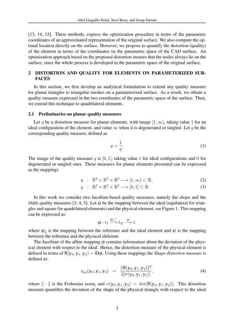
In the third example we apply the smoothing and untangling procedure using the shape dis-tortion measure, Equation (4), to two CAD models composed by multiple patches: a knob and acrank arm. Figure 7(a) shows the initial mesh on the knob. It is composed by 15137 nodes and14521 quadrilateral elements. The initial mesh has intentionally been generated with 497 tan-gled elements. Figure 7(b) presents the smoothed mesh, where all the inverted and degeneratedelements have been untangled. Then, Figure 8(a) presents the initial mesh on the crank arm.
9

Abel Gargallo-Peiro, Xevi Roca, and Josep Sarrate
(a)
(b)
(c)
(d)
(e)
(f)
Figure 6: Meshes colored according to the shape quality measure for a revolution surface: (a) initial mesh, (b)tangled mesh, and (c) smoothed and untangled mesh. Meshes colored according to the shape quality measure fora tubular surface, (d) initial mesh, (e) tangled mesh, and (f) smoothed and untangled mesh.
It is composed by 2966 nodes and 4600 triangular elements. Figure 8(b) presents the resultingmesh from the smoothing procedure.
Table 3 details the shape quality statistics of the presented meshes. Note that the smooth-ing procedure properly improves the quality of the surface mesh in both cases. Moreover, itincreases the minimum and the mean value of the quality of the mesh.
5 CONCLUDING REMARKS
In this work, we have proposed a new and robust technique to smooth and untangle mesheson parameterized surfaces. To this end, we first have developed an analytical procedure to
10
Abel Gargallo-Peiro, Xevi Roca, and Josep Sarrate
(a) (b)
Figure 7: Quadrilateral meshes colored according to the shape quality measure on a knob: (a) initial mesh, and (b)smoothed mesh.
Table 3: Shape quality statistics of the meshes on the knob and a crank arm.
Surface Mesh Figure Min. Q. Max. Q. Mean Q. Std. Dev. Tang. el.
KnobInitial 7(a) 0.00 1.00 0.92 0.20 497
Smoothed 7(b) 0.21 1.00 0.94 0.10 0
Crank armInitial 8(a) 0.00 1.00 0.82 0.12 11
Smoothed 8(b) 0.31 1.00 0.88 0.09 0
extend any Jacobian-based quality measure for planar elements (triangles or quadrilaterals) toparameterized surfaces. Then, using the proposed quality measure, we have presented a newtechnique to optimize (smooth and untangle) meshes on parameterized surfaces. This optimiza-tion process is performed by minimizing the mesh distortion measure (inverse of the quality)expressed on parametric coordinates. In addition, we use the surface parameterization to obtainan analytical expression of the first and second derivatives of the proposed quality measure andto ensure that the nodes move on the surface (via the parameterization mapping). We have pre-sented several examples to illustrate the capabilities of the proposed method. In particular, haveapplied our method using two planar quality measures, and we have untangled highly and ran-domly tangled meshes to test the robustness of the implementation. Finally, we have optimizedtwo multi-patch CAD models to show practical applications of the method.
11

Abel Gargallo-Peiro, Xevi Roca, and Josep Sarrate
(a)
(b)
Figure 8: Triangular meshes for a crank arm colored according to the shape quality measure: (a) initial mesh, and(b) smoothed mesh.
REFERENCES
[1] L. Herrmann. Laplacian-isoparametric grid generation scheme. Journal of the Engineer-ing Mechanics Division, 102(5):749–756, 1976.
[2] S. Giuliani. An algorithm for continuous rezoning of the hydrodynamic grid in arbitrarylagrangian-eulerian computer codes. Nuclear Engineering and Design, 72(2):205–212,1982.
[3] P. M. Knupp. Algebraic mesh quality metrics. SIAM Journal on Numerical Analysis,23(1):193–218, 2001.
[4] P. M. Knupp. Algebraic mesh quality metrics for unstructured initial meshes. FiniteElement in Analysis and Design, 39(3):217–241, 2003.
[5] P. M. Knupp. Label-invariant mesh quality metrics. In Proceedings of the 18th Interna-tional Meshing Roundtable, pages 139–155, Salt Lake City, 2009.
12

Abel Gargallo-Peiro, Xevi Roca, and Josep Sarrate
[6] P. M. Knupp. A method for hexahedral mesh shape optimization. International Journalof Numerical Methods in Engineering, 58(2):319–332, 2003.
[7] J. M. Escobar, E. Rodrıguez, R. Montenegro, G. Montero, and J. M. Gonzalez-Yuste.Simultaneous untangling and smoothing of tetrahedral meshes. Computer Methods inApplied Mechanics and Engineering, 192(25):2775–2787, 2003.
[8] J. M. Escobar, G. Montero, R. Montenegro, and E. Rodrıguez. An algebraic method forsmoothing surface triangulations on a local parametric space. International Journal ofNumerical Methods in Engineering, 66(4):740–760, 2006.
[9] J. M. Escobar, R. Montenegro, E. Rodrıguez, and G. Montero. Simultaneous aligning andsmoothing of surface triangulations. Engineering with Computers, 27(1):17–29, 2011.
[10] P. J. Frey and H. Borouchaki. Geometric surface mesh optimization. Computing andVisualization in Science, 1(3):113–121, 1998.
[11] X. Jiao, D. Wang, and H. Zha. Simple and effective variational optimization of surfaceand volume triangulations. Engineering with Computers, 27:81–94, 2011.
[12] D. Vartziotis, T. Athanasiadis, I. Goudas, and J. Wipper. Mesh smoothing using the ge-ometric element transformation method. Computer Methods in Applied Mechanics andEngineering, 197:3760–3767, 2008.
[13] R. Garimella, M. Shashkov, and P. M. Knupp. Triangular and quadrilateral surface meshquality optimization using local parametrization. Computer Methods in Applied Mechan-ics and Engineering, 193(9–11):913–928, 2004.
[14] R. Garimella and M. Shashkov. Polygonal surface mesh optimization. Engineering withComputers, 20(3):265–272, 2004.
[15] K. Shivanna, N. Grosland, and V. Magnotta. An analytical framework for quadrilateral sur-face mesh improvement with an underlying triangulated surface definition. In Proceedingsof the 19th International Meshing Roundtable, pages 85–102, Chattanooga, 2010.
[16] X. Roca, E. Ruiz-Girones, and J. Sarrate. ez4u: Mesh generation environment.www-lacan.upc.edu/ez4u.htm, 2010.
[17] X. Roca, J. Sarrate, and E. Ruiz-Girones. Congreso de metodos numericos y computa-cionales en ingenierıa, semni. In Communications in Numerical Methods in Engineering,Porto, 2007.
[18] X. Roca. Paving the path towards automatic hexahedral mesh generation. PhD thesis,Universitat Politecnica de Catalunya, 2009.
13