Embed Size (px)
Citation preview

KIT – University of the State of Baden-Wuerttemberg and National Research Center of the Helmholtz Association www.kit.edu
Karlsruhe Institute of Technology (KIT), Campus NordInstitute for Technical Chemistry – Thermal Waste Treatment DivisionPostfach 3640, D-76021 Karlsruhe, GermanyE-mail: [email protected]
A new technology for high efficient Waste-to-Energy plants
Hans Hunsinger
Institute for Technical Chemistry - ITC-TAB2 H. Hunsinger - ICIPEC 2010
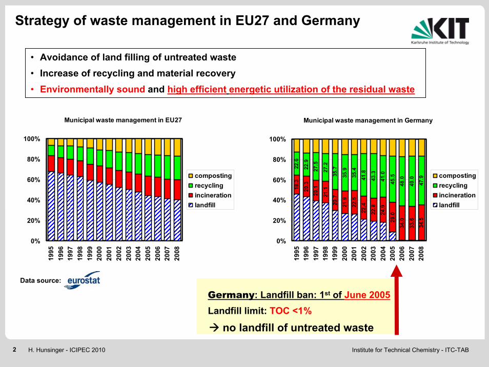
Municipal waste management in Germany
18.3
20.3
20.1
21.1
20.7
21.9
22.5
22.4
22.8
24.9
29.0
34.0
33.6
34.5
22.6
22.9
27.5
27.2
35.7
35.9
35.4
41.8
43.3
41.0
45.5
48.0
49.0
47.9
0%
20%
40%
60%
80%
100%
1995
1996
1997
1998
1999
2000
2001
2002
2003
2004
2005
2006
2007
2008
compostingrecyclingincinerationlandfill
Municipal waste management in EU27
0%
20%
40%
60%
80%
100%
1995
1996
1997
1998
1999
2000
2001
2002
2003
2004
2005
2006
2007
2008
compostingrecyclingincinerationlandfill
Germany: Landfill ban: 1st of June 2005Landfill limit: TOC <1%
Data source:
no landfill of untreated waste
Strategy of waste management in EU27 and Germany
• Avoidance of land filling of untreated waste• Increase of recycling and material recovery • Environmentally sound and high efficient energetic utilization of the residual waste
Institute for Technical Chemistry - ITC-TAB3 H. Hunsinger - ICIPEC 2010
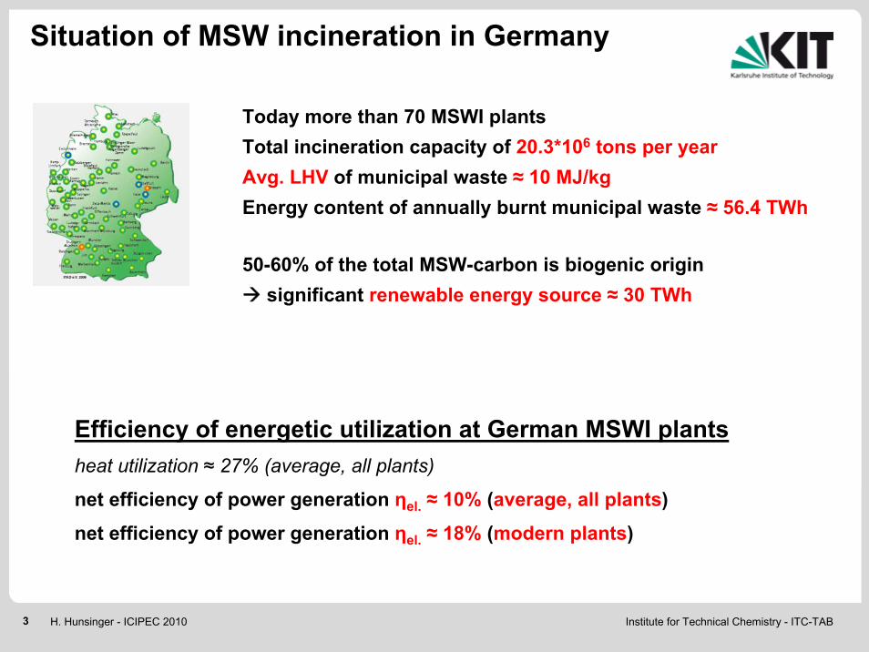
Today more than 70 MSWI plants Total incineration capacity of 20.3*106 tons per yearAvg. LHV of municipal waste ≈ 10 MJ/kgEnergy content of annually burnt municipal waste ≈ 56.4 TWh
Efficiency of energetic utilization at German MSWI plantsheat utilization ≈ 27% (average, all plants)
net efficiency of power generation ηel. ≈ 10% (average, all plants)
net efficiency of power generation ηel. ≈ 18% (modern plants)
Situation of MSW incineration in Germany
50-60% of the total MSW-carbon is biogenic originsignificant renewable energy source ≈ 30 TWh
Institute for Technical Chemistry - ITC-TAB4 H. Hunsinger - ICIPEC 2010
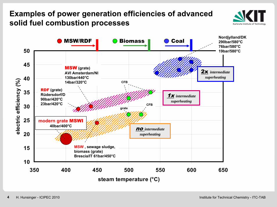
Examples of power generation efficiencies of advanced solid fuel combustion processes
10
15
20
25
30
35
40
45
50
350 400 450 500 550 600 650steam temperature (°C)
elec
tric
effic
ienc
y (%
)
Nordjylland/DK290bar/580°C76bar/580°C19bar/580°C
MSW (grate)AVI Amsterdam/Nl130bar/440°C14bar/320°C
RDF (grate)Rüdersdorf/D90bar/420°C23bar/420°C
modern grate MSWI40bar/400°C
1x intermediate superheating
no intermediate superheating
2x intermediate superheating
MSW , sewage sludge, biomass (grate)Brescia/IT 61bar/450°C
CFB
grateCFB
MSW/RDF Biomass Coal
Institute for Technical Chemistry - ITC-TAB5 H. Hunsinger - ICIPEC 2010
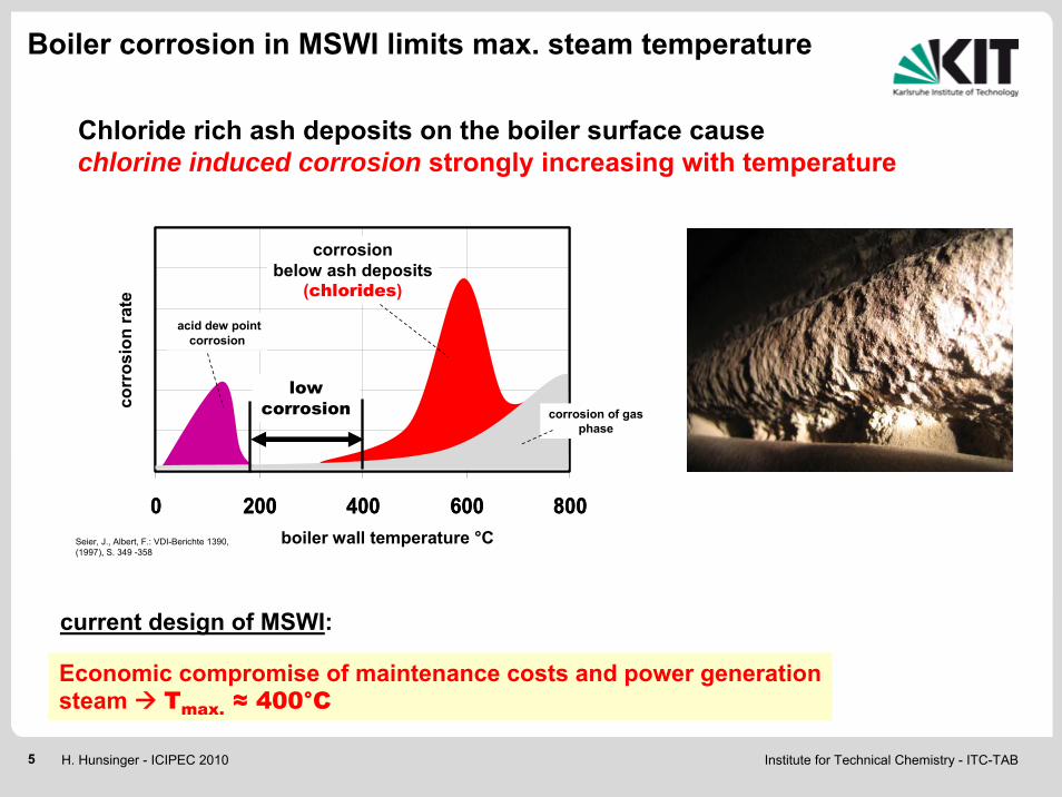
Boiler corrosion in MSWI limits max. steam temperature
0 200 400 600 8000 200 400 600 800
corrosionbelow ash deposits
(chlorides)
corrosion of gas phase
acid dew pointcorrosion
boiler wall temperature °C
corr
osio
n ra
te
low corrosion
Chloride rich ash deposits on the boiler surface cause chlorine induced corrosion strongly increasing with temperature
Economic compromise of maintenance costs and power generationsteam Tmax. ≈ 400°C
Seier, J., Albert, F.: VDI-Berichte 1390, (1997), S. 349 -358
current design of MSWI:
Institute for Technical Chemistry - ITC-TAB6 H. Hunsinger - ICIPEC 2010
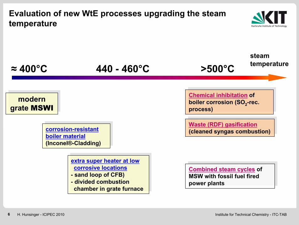
Evaluation of new WtE processes upgrading the steam temperature
corrosion-resistant boiler material(Inconel®-Cladding)
corrosion-resistant boiler material(Inconel®-Cladding)
steam temperature
Chemical inhibitation of boiler corrosion (SO2-rec. process)
Chemical inhibitation of boiler corrosion (SO2-rec. process)
Combined steam cycles of MSW with fossil fuel fired power plants
Combined steam cycles of MSW with fossil fuel fired power plants
440 - 460°C >500°C
extra super heater at low corrosive locations
- sand loop of CFB) - divided combustion chamber in grate furnace
extra super heater at low corrosive locations
- sand loop of CFB) - divided combustion chamber in grate furnace
Waste (RDF) gasification(cleaned syngas combustion)
Waste (RDF) gasification(cleaned syngas combustion)
≈ 400°C
modern grate MSWI
modern grate MSWI

Institute for Technical Chemistry - ITC-TAB7 H. Hunsinger - ICIPEC 2010
Measures for maximized electricity generation from MSWI
• High temperature steam generation at low boiler corrosion
• Intermediate steam reheating (high/low pressure steam cycle)
• Low pressure/temperature of steam condensation (no heat utilization)
• Regenerative condensate preheating
Minimized heat lossMinimized heat loss
Optimization of the Rankine cycle approach to Carnot efficiency
Optimization of the Rankine cycle approach to Carnot efficiency
• Low excess air combustion
• Low flue gas temperature at boiler exit
Low energy consumption of the plant
Low energy consumption of the plant
• Avoidance of pollutant formation (NOx, PCDD/F reduced efforts in flue gas cleaning)
• Low quantity and good quality of residues (TOC, PAH) like in modern MSWI (no residue treatment)

Institute for Technical Chemistry - ITC-TAB8 H. Hunsinger - ICIPEC 2010
T (°
C)
0
200
400
600
800
1000
C (%
)
0
20
40
60
80
100
O2 (
Vol.%
)
0
5
10
15
20
25
Characteristics of MSW combustion in a grate furnace
zone 1 zone 2 zone 3 zone 4
primary airfuel bed
TO2
C
drying pyrolysisgasification fixed carbon burnout
λ>1λ<1λ>1bottom ashMSW
grate

Institute for Technical Chemistry - ITC-TAB9 H. Hunsinger - ICIPEC 2010
Characteristics of MSW combustion in a grate furnace
zone 1 zone 2 zone 3 zone 4
primary airfuel bed
drying pyrolysisgasification fixed carbon burnout
λ>1λ<1λ>1bottom ashMSW
flue gas burn out zone
secondary air
flue gas λ>1steam boiler
λ<1 λ<1
Institute for Technical Chemistry - ITC-TAB10 H. Hunsinger - ICIPEC 2010
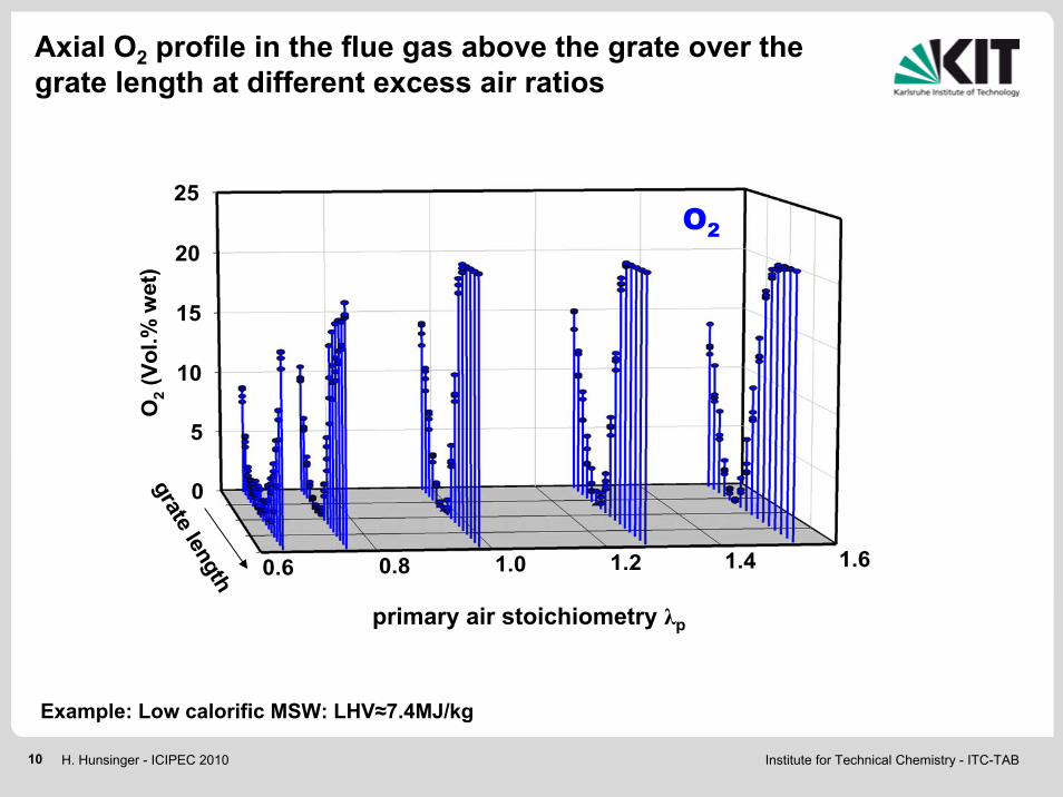
Example: Low calorific MSW: LHV≈7.4MJ/kg
Axial O2 profile in the flue gas above the grate over the grate length at different excess air ratios
0
5
10
15
20
25
0.6 0.8 1.0 1.2 1.4 1.6
O2 (
Vol.%
wet
)
grate length
λpprimary air stoichiometry λp
O2

Institute for Technical Chemistry - ITC-TAB11 H. Hunsinger - ICIPEC 2010
Products of uncompleted combustion (PICs)
0.0
0.5
1.0
1.5
2.0
2.5
0.6 0.8 1.0 1.2 1.4 1.6
soot
(g/m
3 wet
)
grate length
λp
0
2
4
6
8
0.6 0.8 1.0 1.2 1.4 1.6
CO
(Vol
.% w
et)
grate length
λp
0
10
20
30
40
0.6 0.8 1.0 1.2 1.4 1.6
CnH
m (g
/m3 w
et)
grate length
λp
0.0
0.5
1.0
1.5
2.0
2.5
0.6 0.8 1.0 1.2 1.4 1.6
H2 (
Vol.%
wet
)
grate length
λpPrimary air stoichiometry λp Primary air stoichiometry λp
Primary air stoichiometry λp Primary air stoichiometry λp
CO
H2CnHm
Soot particles
Institute for Technical Chemistry - ITC-TAB12 H. Hunsinger - ICIPEC 2010
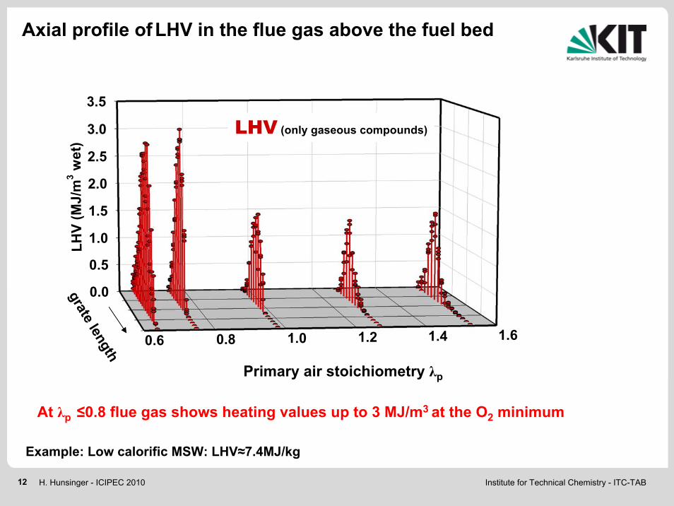
At λp ≤0.8 flue gas shows heating values up to 3 MJ/m3 at the O2 minimum
0.0
0.5
1.0
1.5
2.0
2.5
3.0
3.5
0.6 0.8 1.0 1.2 1.4 1.6
LHV
(MJ/
m3 w
et)
grate length
λpPrimary air stoichiometry λp
LHV (only gaseous compounds)
Axial profile ofLHV in the flue gas above the fuel bed
Example: Low calorific MSW: LHV≈7.4MJ/kg
Institute for Technical Chemistry - ITC-TAB13 H. Hunsinger - ICIPEC 2010
soot
par
ticle
s
CnH
m
met
hane
ethe
ne
ethy
ne
benz
ene
tolu
ene
naph
thal
ene
phen
anth
rene
anth
race
ne
fluor
anth
ene
pyre
ne
pyrid
ine
0.001
0.01
0.1
1
10
100
C2H
2
CH
4
C2H
4
C6H
6
C7H
8
C10
H8
C14
H10
C14
H10
C16
H10
C5H
5N
ΣC
nHm
soot
C16
H10
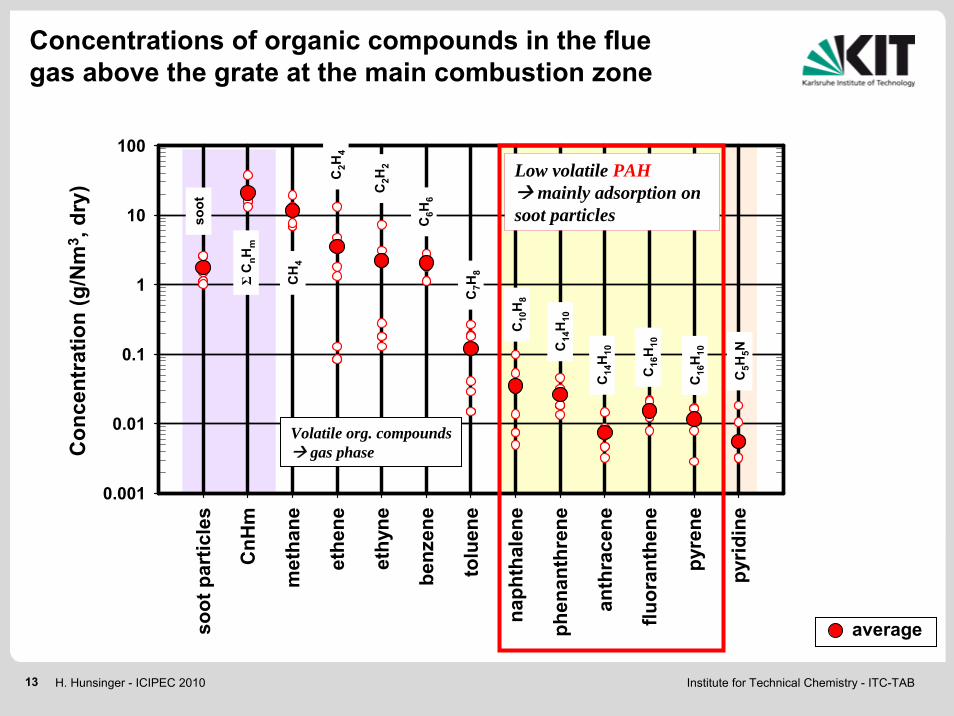
average
Volatile org. compoundsgas phase
Low volatile PAHmainly adsorption on
soot particles
Con
cent
ratio
n (g
/Nm
3 , dr
y)Concentrations of organic compounds in the flue gas above the grate at the main combustion zone
Institute for Technical Chemistry - ITC-TAB14 H. Hunsinger - ICIPEC 2010
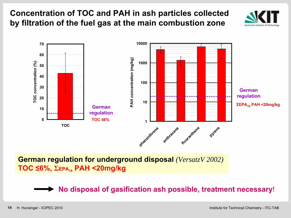
German regulation for underground disposal (VersatzV 2002)TOC ≤6%, ΣEPA16 PAH <20mg/kg
Concentration of TOC and PAH in ash particles collected by filtration of the fuel gas at the main combustion zone
0
10
20
30
40
50
60
70
TOC
TOC
con
cent
ratio
n (%
)
No disposal of gasification ash possible, treatment necessary!
1
10
100
1000
10000
phenan
threne
anthrac
ene
fluor
anthen
e
pyrene
PAH
con
cent
ratio
n (m
g/kg
)
German regulation
German regulation
ΣEPA16 PAH <20mg/kg
TOC ≤6%
Institute for Technical Chemistry - ITC-TAB15 H. Hunsinger - ICIPEC 2010
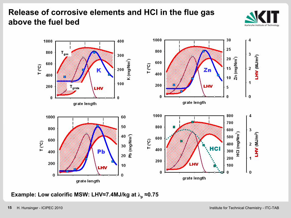
Release of corrosive elements and HCl in the flue gas above the fuel bed
Example: Low calorific MSW: LHV≈7.4MJ/kg at λp ≈0.75

Institute for Technical Chemistry - ITC-TAB16 H. Hunsinger - ICIPEC 2010
grate zones
NO
, NH
3 (m
g/N
m3 )
0
500
1000
1500
2000
2500
O2 (
Vol.
%)
0
5
10
15
20
25
O2
NH3
NO
Concentration of N-compounds in the flue gas above the fuel bed
Hunsinger et al., 5th i-CIPEC, 16-19 December 2008, Chiang Mai, Thailand
Institute for Technical Chemistry - ITC-TAB17 H. Hunsinger - ICIPEC 2010
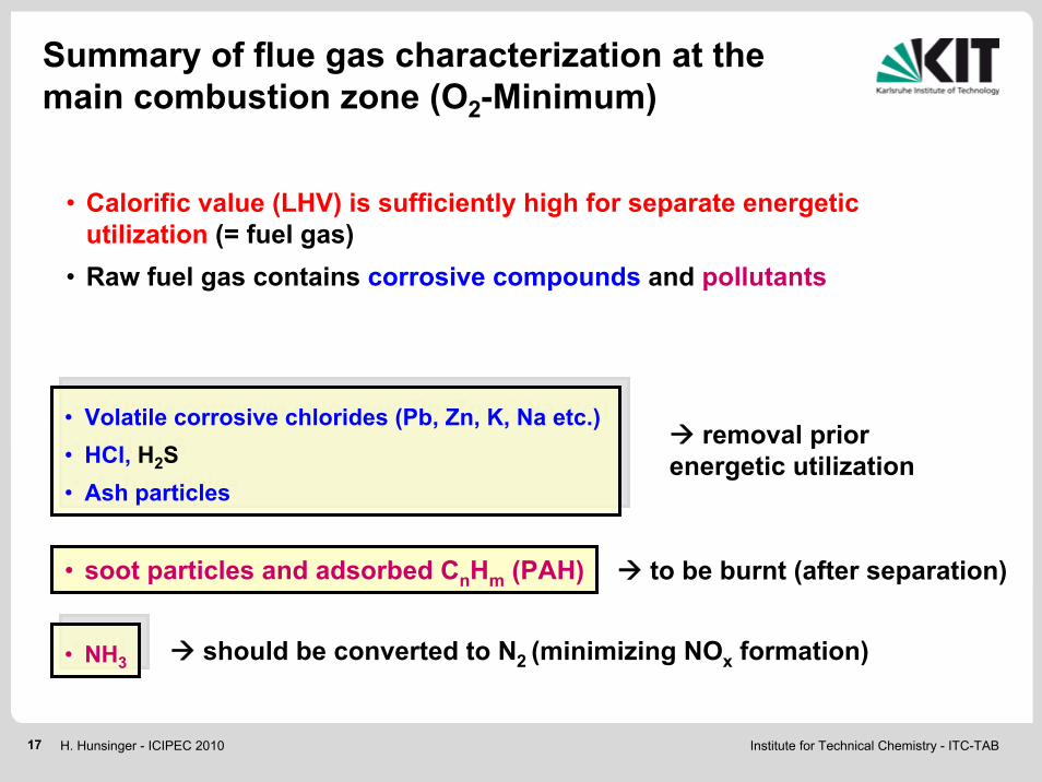
• Calorific value (LHV) is sufficiently high for separate energetic utilization (= fuel gas)
• Raw fuel gas contains corrosive compounds and pollutants
• Volatile corrosive chlorides (Pb, Zn, K, Na etc.) • HCl, H2S• Ash particles
• Volatile corrosive chlorides (Pb, Zn, K, Na etc.) • HCl, H2S• Ash particles
Summary of flue gas characterization at the main combustion zone (O2-Minimum)
removal prior energetic utilization
• NH3• NH3
to be burnt (after separation)
should be converted to N2 (minimizing NOx formation)
• soot particles and adsorbed CnHm (PAH)

Institute for Technical Chemistry - ITC-TAB18 H. Hunsinger - ICIPEC 2010
gasification ash(chlorides, soot, PAH)
+ CaCl2air
2) Hot gas filtration + dry sorption of HCl (H2S)
3) Combustion of the cleaned fuel gas
4) Heat utilization for steam super heating
Ca(OH)2
Raw fuel gas
air
Flue gas
≈900°C
1) Cooling to T≈400°C(Condensation of volatile chlorides, avoiding tar condensation)
Fuel gas cleaning and energetic utilization
NOx
Institute for Technical Chemistry - ITC-TAB19 H. Hunsinger - ICIPEC 2010
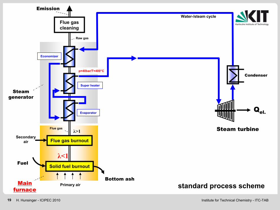
Raw gas
Water-/steam cycle
Main furnace
Primary air
Flue gas
Emission
Steam generator
Steam turbine
Condenser
Economizer
Super heater
Evaporator
Secondary air
Flue gas cleaning
Qel.
p=40bar/T=400°C
Bottom ashstandard process scheme
Flue gas burnout
Solid fuel burnoutFuel
λ<1
λ>1

Institute for Technical Chemistry - ITC-TAB20 H. Hunsinger - ICIPEC 2010
ash(soot) + CaCl2
Raw gas
Water-/steam cycle
Main furnace
air
Primary air
Flue gas
≈400°C
Emission
2) Hot gasfiltration
+ dry sorptionSteam
generator
3) Secondarycombustionchamber
Steam turbine
Condenser
4) Superheater SH2
Economizer
Super heater SH1
Evaporator
Secondary air
Ca(OH)2
Flue gas cleaning
Qel.
1) Heatexchanger
p=120bar/T=540°C
T=400°C
Fuel gas
air
Bottom ashscheme of new process
Flue gas burnout
Solid fuel burnoutFuel
(MSW) Bypass flue gasλ<1
λ>1
Bypass process
p=120bar
≈900°C
≈600°C

Institute for Technical Chemistry - ITC-TAB21 H. Hunsinger - ICIPEC 2010
Reduction of pollutants
Ash from fuel gas filtration• TOC and PAH are burned when feeding back into the combustion chamber of the
main furnace (prior secondary air supply)• Heavy metals, chlorides and formed HCl will be collected in the flue gas
cleaning system of the main furnace
• NH3 in the fuel gas forms NOx during combustion in the bypass furnace
• NOx will be destroyed when injecting the by-pass flue gas back into the reducing atmosphere of the main furnace prior secondary air supply
4NO + 4NH3 + O2 4N2 + 6H2O2NO + 2CO N2 + 2CO2
Flue gas of the bypass combustion process
Re-burn
SNCR
Institute for Technical Chemistry - ITC-TAB22 H. Hunsinger - ICIPEC 2010
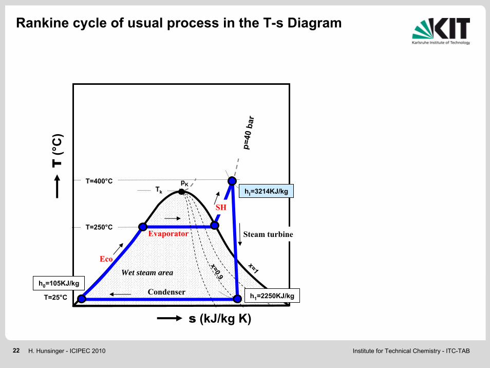
p=40
bar
T(°
C)
s (kJ/kg K)
T=400°C
Wet steam area
T=250°C
hI=3214KJ/kg
T=25°C
x=0.9
Evaporator
Eco
h1=2250KJ/kg
SH
Tk
Condenser
Steam turbinex=1
pK
h0=105KJ/kg
Rankine cycle of usual process in the T-s Diagram

Institute for Technical Chemistry - ITC-TAB23 H. Hunsinger - ICIPEC 2010
12% heat transfer in SHII
p=40
bar
T(°
C)
s (kJ/kg K)
T=400°C
Wet steam area
T=250°C
hI=3214KJ/kg
T=540°C
p=12
0 ba
r
hII=3455KJ/kg
T=25°C
h=3051KJ/kg
x=0.9
SH1
SH2
Evaporator
Eco
T=325°C
h1=2250KJ/kg
SH
Tk
Condenser
Steam turbinex=1
pK
h0=105KJ/kg
87.9
12.1
0
10
20
30
40
50
60
70
80
90
100
Ener
gy tr
ansf
er to
ste
am (%
)
Main boilerEco, EvaporatorSH1
Extra super heater (SH2)
120bar/540°C
Rankine cycle of the new process in the T-s Diagram

Institute for Technical Chemistry - ITC-TAB24 H. Hunsinger - ICIPEC 2010
Increase of ηel.≈ 4% points
T=400°C
T=24°C
T=540°Cp=12
0 ba
r
p=40
bar
x=1
p=0.03 bar
x=0.9
hII=3455kJ/kg
hI=3051kJ/kg
h=2250kJ/kg
s (kJ/kg K)
h(k
J/kg
)
∆ht 1
20ba
r/540
°C
∆ht 4
0bar
/400
°C
ηT ≈ 0.83Steam turbine
Power generation by an axial steam turbineStandard process: 40bar/400°CExample of the new process: 120bar/540°C
Institute for Technical Chemistry - ITC-TAB25 H. Hunsinger - ICIPEC 2010
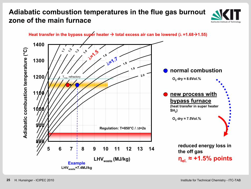
800
900
1000
1100
1200
1300
1400
5 6 7 8 9 10 11 12 13 14
Regulation: T=850°C / ∆t=2s
normal combustion
new process with bypass furnace(heat transfer in super heater SH2)
λ=1.7
1.9
1.41.31.2
2.0
1.1
Adi
abat
ic c
ombu
stio
n te
mpe
ratu
re (°
C)
LHVwaste (MJ/kg)Example
LHVwaste=7.4MJ/kg
Heat transfer in the bypass super heater total excess air can be lowered (λ =1.68 1.55)
O2 dry ≈ 8.6Vol.%
O2 dry ≈ 7.5Vol.%
λ=1.5
1.8
1.6
reduced energy loss in the off gasηel. ≈ +1.5% points
Adiabatic combustion temperatures in the flue gas burnout zone of the main furnace
Tmax. refractory

Institute for Technical Chemistry - ITC-TAB26 H. Hunsinger - ICIPEC 2010
Economic benefit (for the example)
MSWI with thermal capacity of 50MWOperation time per year: 8000hPrice for electricity in Germany: ≈50€/MWh
1.1 million € per yearAdditional profit:
Increase of power generation +5.5% points

Institute for Technical Chemistry - ITC-TAB27 H. Hunsinger - ICIPEC 2010
p 1
TSH
K
Wet steam area
Evaporator
Eco
CondenserTC
T(°
C)
s (KJ/kg K)
Steam turbine
Super heater
p 1
TSH
K
Wet steam area
Evaporator
Eco
CondenserTC
T(°
C)
s (KJ/kg K)
Steam turbine
Super heater
p 1
p 2
TSH
K
Wet steam area
Evaporator
Eco
CondenserTC
T(°
C)
s (KJ/kg K)
Steam turbine
Super heater
p 3Intermediate steam reheating
Rankine cycle (high/medium/low pressure) like in modern power plants
ηel. >35% possible
The new process allows high steam super heating(T»500°C) avoiding chlorine induced boiler corrosion and super heater fouling
Further increase of power generation efficiency
p 1
p 2
TSH
K
Wet steam area
Evaporator
Eco
CondenserTC
T(°
C)
s (KJ/kg K)
Steam turbine
Super heater
40bar/400°C T »500°C
T »500°C T »500°C

Institute for Technical Chemistry - ITC-TAB28 H. Hunsinger - ICIPEC 2010
Secondary air
Primary air
Flue gas
λ<1
λ>1
Fuel gas
Flue gas IIRecirculation
MSW+ sand
Bottom ash+ sand
Flue gas burnout zone
Cyclone
sand + coarse ash
air
λ<1
•Gas cleaning•Combustion•Super heating
ash
Application in various combustion systems
Grate furnace Fluidized bed furnace
Fuels: MSW, Biomass etc.
•Gas cleaning•Combustion•Super heating
Z1 Z2 Z3Z4
Primary air
Secondary air
MSW
Bottom ash
Fuel gas
Flue gas IIRecirculation
air
λ<1
λ>1
λ>1
λ>1
λ<1
Flue gas burnoutzone
Flue gas
ash
Institute for Technical Chemistry - ITC-TAB29 H. Hunsinger - ICIPEC 2010
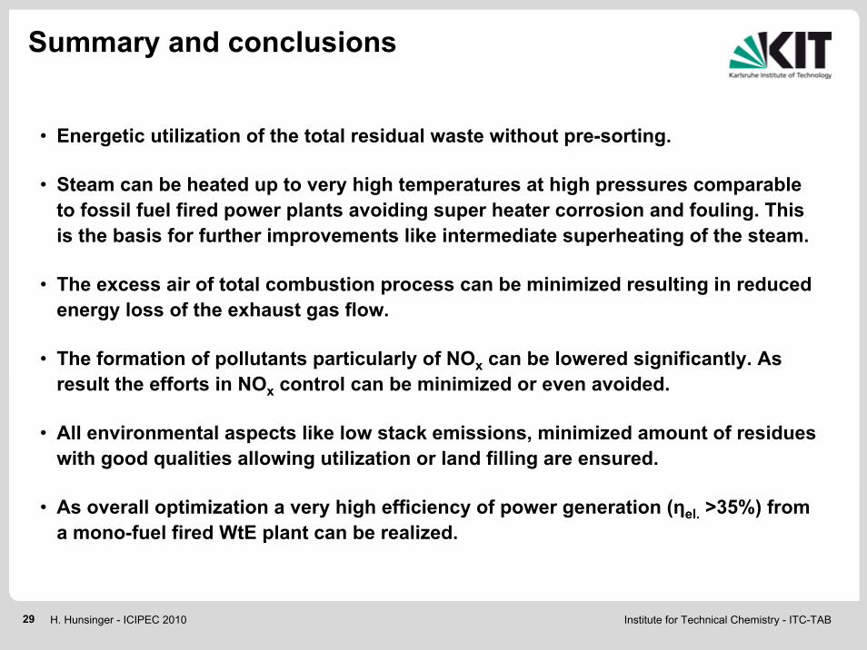
Summary and conclusions
• Energetic utilization of the total residual waste without pre-sorting.
• Steam can be heated up to very high temperatures at high pressures comparable to fossil fuel fired power plants avoiding super heater corrosion and fouling. This is the basis for further improvements like intermediate superheating of the steam.
• The excess air of total combustion process can be minimized resulting in reduced energy loss of the exhaust gas flow.
• The formation of pollutants particularly of NOx can be lowered significantly. As result the efforts in NOx control can be minimized or even avoided.
• All environmental aspects like low stack emissions, minimized amount of residues with good qualities allowing utilization or land filling are ensured.
• As overall optimization a very high efficiency of power generation (ηel. >35%) from a mono-fuel fired WtE plant can be realized.


![INTERNET2 UPDATE & FUTURE GOVERNMENT ...INTERNET2 UPDATE & FUTURE GOVERNMENT SUPPORTED PROJECTS Ana [Preston] Hunsinger CUDI –Reunion de Otono Puerto Vallarta, Jalisco, Mexico November](https://img.pdfslide.net/doc/110x75/5f42a17a8e07ae6c202b3d2d/internet2-update-future-government-internet2-update-future-government.jpg)