Embed Size (px)
Citation preview
8/4/2019 A NEW TREND IN IMPROVING EFFICIENCY OF TRANSMISSION LINES IN
http://slidepdf.com/reader/full/a-new-trend-in-improving-efficiency-of-transmission-lines-in 1/8
A NEW TREND IN IMPROVING EFFICIENCY OF TRANSMISSION
LINES IN POWER SYSTEM
Sangathamilan.D [1], Prabhu.T [2], Final year EEE,
Hindusthan College of Engineering and Technology,
Othakalmandapam Post, [email protected], [email protected]
Abstract:
It is common knowledge that
transmission systems are being pushed
ever closer to their stability and thermal
limits. Traditional solutions for
upgrading electrical transmission system
infrastructure have been primarily in the
form of new power plants, new transmission lines, substations, and
associated equipment. However, as
experience has proven, the process of
authorizing, locating, and constructing
new transmission lines has become
extremely difficult, expensive and time-
consuming. This is the reason why
during the last few years interest in
dispersed generation, power flow
controlling or/and energy storage has
increased significantly – interest in
solutions which can improve the
efficiency of the distributed power system.
With respect to the above the major aim
of this paper is to present the
fundamental problems of the Power
Systems and the improvement methods
which arise using Distributed
Generation. The paper introduces also a
system for the utilization of energy
generated on the customer side – thisarrangement is realised using a Voltage
Active Power Filter. The experimental
results presented in the paper confirm the
flexibility of this arrangement in
efficiency improvement processes
1. Introduction
Today, most users are in active receivers
of electricity without further involvement
in the management of the sources and thegrid; each user is simply a hole for
electrical energy. Additionally, much of
the equipment of today’s Polish Electrical
Power System (EPS) was installed with a
nominal design life of about 30–40 years;
meanwhile, the size of the load has grownabove what was predicted when the grid
was designed. In response to the above and
to the climate change challenge, which is
forcing reduction of greenhouse gases
emissions, Poland and other European
countries have started the process of
liberalization of their electrical power
systems, opening access to grids and
encouraging renewable energy sources. In
this situation, there is a great opportunity
for Distributed Generation (DG) and other
new players to provide better network
capability, flexibility and functionality –
improvement in the efficiency. As a result,
the amount of electrical energy produced
by large conventional plants will be
displaced by DGs, demand response and
energy storage. Taking into consideration
the above, the major aim of this paper is to
introduce the fundamental problems of
Electrical Power Systems and, secondly, toreview efficiency improvement services to
grids provided with inverter interfaced
Distributed Generation. The paper
introduces also some power electronics
based solutions, which form a basis for
building single as well as multilane
DG/EPS interfaces.
2. Structure and fundamental problems
of Electrical Power Systems:

8/4/2019 A NEW TREND IN IMPROVING EFFICIENCY OF TRANSMISSION LINES IN
http://slidepdf.com/reader/full/a-new-trend-in-improving-efficiency-of-transmission-lines-in 2/8
Today’s grids are primarily based on large
power stations connected to transmission
lines which supply power to distribution
systems, thus the overall image remains
the same as ever: one-way power flow
from the power stations, via thetransmission and distribution systems, to
the final customer (end-user). The one-line
diagram shown in Fig. 1 illustrates today’s
Electrical Power System and its major
components: generation, transmission and
distribution. Electric power is generated at
power stations predominantly by
synchronous generators that are mostly
driven by steam or hydro turbines. Hence,
the electric power generated at any such
station usually has to be transmitted over agreat distance, through transmission
systems to distribution systems. The
distribution networks distribute the energy
from the transmission grid or small/local
Distributed Resources (DR) to customers.
The three mentioned components
generation, transmission and distribution
have different influences, individual and
sometimes common, on the efficiency of
power system. There are many issues
involved, such as the maintenance of
power apparatuses and the system, the
stability of the operation system, faults,
distortions, loads and non-linearities etc.
2.1. Transmission systems:
Transmission systems are being pushedever closer to their stability and thermal
limits and if the facilities are not suitably
upgraded the power system becomes
vulnerable to steady-state and transient
stability problems. In such environments,
transmission capacity becomes a virtue;
therefore during the last few years’ interest
in the possibilities for controlling power
flows in transmission systems, dispersed
generation or energy storage has increased
significantly. Traditional solutions for upgrading electrical transmission system
infrastructure have been primarily in the
form of new power plants, new
transmission lines, substations, and
associated equipment. However, as
experience has proven, the process of
authorizing, locating, and constructing new
transmission lines has become extremely
difficult, expensive and time-consuming. It
is envisaged that, alternatively, Flexible
Alternating Current Transmission System
(FACTS), Energy Storage Systems (ESS)
and Distributed Generation can enable the
same objectives to be met. The potential
benefits of employing the above-
mentioned solutions include reduction of
operation and transmission investment
costs and implementation time compared
to the construction of new transmission
lines, increased system security and
reliability, increased power transfer capabilities, and an overall enhancement of
the quality of the electric energy delivered
to customers.
2.2. Distribution systems:
With the emergence of computers,
sensitive loads and modern
communications, a reliable electricity
supply with high quality voltage has
become a necessity. Voltage sags and dipscan cause loss of production in automated
8/4/2019 A NEW TREND IN IMPROVING EFFICIENCY OF TRANSMISSION LINES IN
http://slidepdf.com/reader/full/a-new-trend-in-improving-efficiency-of-transmission-lines-in 3/8
processes, and can also force a computer
system or data processing system to crash.
A sustained overvoltage can cause damage
to household appliances. An under voltage
has the same effect as that of voltage sag.
Voltage imbalance can cause temperaturerises in motors. Harmonics, DC offset, can
cause waveform distortions. Unwanted
current harmonics flowing across the
distribution network can cause losses and
heating in transformers and
Electromagnetic Interference (EMI). Inter
harmonics voltages can upset the operation
of fluorescent lamps and television
receivers. They can also produce acoustic
noise. It can be concluded that the lack of
quality power can cause loss of production, and damage to equipment. As
with FACTS and other players in
transmission systems, power electronics
devices called Custom Power Systems
(CUPS) together with ESS, DG and smart
end-user appliances can be applied to the
power distribution systems to increase
reliability and quality of power supplied to
customers. Through those technologies the
reliability and quality of the power
delivered can be improved in terms of
reduced interruptions, reduced voltage,
current variations and distortions. The
proper use of these technologies will
benefit all industrial, commercial and
domestic customers.
3. Distributed Generation’s efficiency
improvement services:
As Distributed Generation hardware becomes more reliable and economically
feasible, there is a trend to connect DG
units to the existing utilities to serve
different purposes and offer more
possibilities to power system users. DG
can bring some relief for Transmission and
Distribution (T&D) capacity and these
new energy injections can have some
benefits in the operation on the whole
EPS:
• The production of energy near the load
reduces the losses of the grids, because
energy is generated where it is consumed.
• The existence of DG units could be an
important way to increase the voltage; the
insertion of a DG in a bus raises itsvoltage.
• End-users who place DG can benefit by
having backup generation to improve
reliability. Distributed Generation
hardware can also secure the power flow
control actions. There are a number of
reasons for this:
• In a meshed power system, there can
occur a situation where a low impedance
line carries much more power than
originally designed for, while parallel paths are underutilized. With power flow
control, the stressed line can be relieved,
resulting in better overall utilization of the
network.
• Both low voltage as well as high voltage
can exceed the voltage limits and therefore
corrective actions have to be taken. The
corrective actions with utilization of
selected FACTS devices include correcting
the power factor and compensating
reactive losses in lines by supplying
reactive power.
• Transient and dynamic stability control
issues-transient stability describes the
ability of the power system to survive after
a major disturbance, while dynamic
stability describes sustained or growing
power swing oscillations between
generators or a group of generators
initiated by a disturbance. In the first as
well as the second situation, active power flow control can be a solution.
Summarizing, power flow control
technologies have the abilities to solve
both steady-state (better utilization of the
transmission assets, minimization of
losses, limit flows to contract paths etc.)
and dynamic issues (dynamic dumping of
the oscillations) of transmission systems.
Considering the above the only concern is
to find DGs/EPS interconnection solution
which is suitable to secure all aboveactions.
8/4/2019 A NEW TREND IN IMPROVING EFFICIENCY OF TRANSMISSION LINES IN
http://slidepdf.com/reader/full/a-new-trend-in-improving-efficiency-of-transmission-lines-in 4/8
4. Design and build of a DGs/EPS
Interconnection systems:
4.1. Stand-alone systems (off-line/off-
grid):
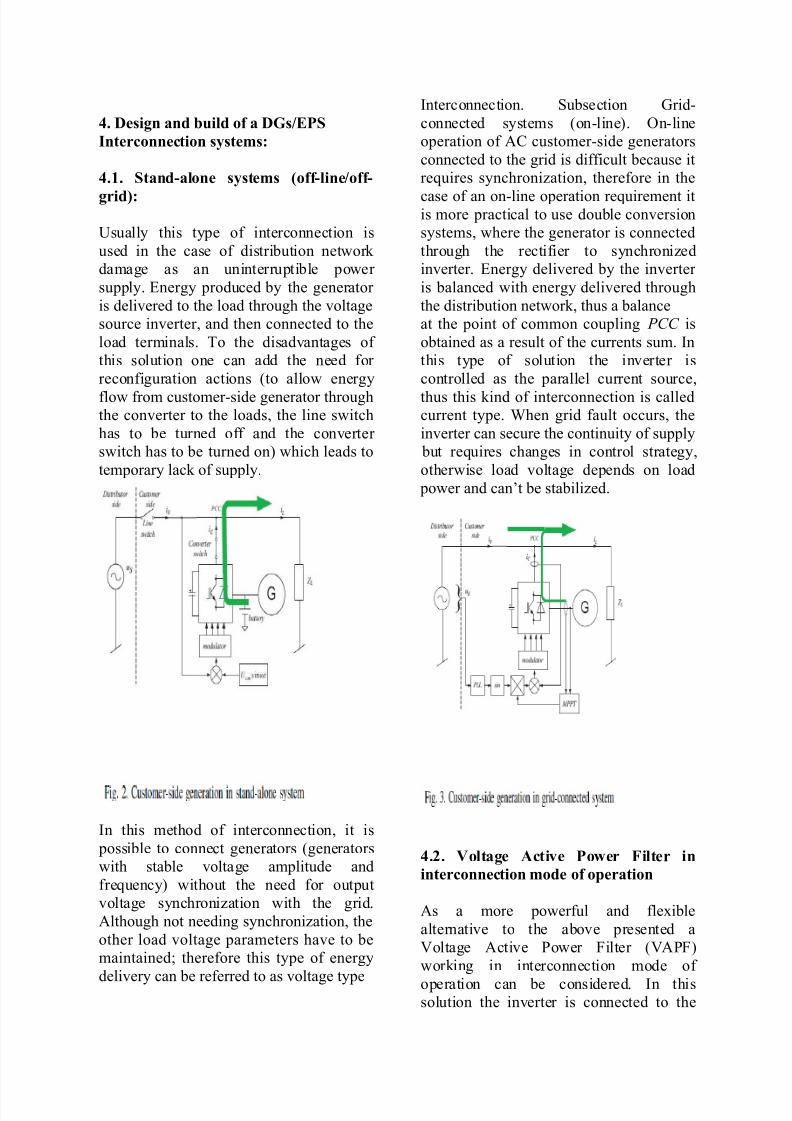
Usually this type of interconnection is
used in the case of distribution network
damage as an uninterruptible power
supply. Energy produced by the generator
is delivered to the load through the voltage
source inverter, and then connected to the
load terminals. To the disadvantages of
this solution one can add the need for
reconfiguration actions (to allow energy
flow from customer-side generator throughthe converter to the loads, the line switch
has to be turned off and the converter
switch has to be turned on) which leads to
temporary lack of supply.
In this method of interconnection, it is
possible to connect generators (generators
with stable voltage amplitude and
frequency) without the need for output
voltage synchronization with the grid.
Although not needing synchronization, the
other load voltage parameters have to be
maintained; therefore this type of energy
delivery can be referred to as voltage type
Interconnection. Subsection Grid-
connected systems (on-line). On-line
operation of AC customer-side generators
connected to the grid is difficult because it
requires synchronization, therefore in the
case of an on-line operation requirement itis more practical to use double conversion
systems, where the generator is connected
through the rectifier to synchronized
inverter. Energy delivered by the inverter
is balanced with energy delivered through
the distribution network, thus a balance
at the point of common coupling PCC is
obtained as a result of the currents sum. In
this type of solution the inverter is
controlled as the parallel current source,
thus this kind of interconnection is calledcurrent type. When grid fault occurs, the
inverter can secure the continuity of supply
but requires changes in control strategy,
otherwise load voltage depends on load
power and can’t be stabilized.
4.2. Voltage Active Power Filter in
interconnection mode of operation
As a more powerful and flexible
alternative to the above presented a
Voltage Active Power Filter (VAPF)
working in interconnection mode of
operation can be considered. In thissolution the inverter is connected to the

8/4/2019 A NEW TREND IN IMPROVING EFFICIENCY OF TRANSMISSION LINES IN
http://slidepdf.com/reader/full/a-new-trend-in-improving-efficiency-of-transmission-lines-in 5/8
network terminals through the series
reactance XS and then directly to the load.
The whole arrangement can be broken
down into three major parts: the Grid Side
Inverter (GSI)(T1-T4), the DC link (C1)
and the Generator Side Converter (GSC)(T5, T6 ). In the proposed solution, the grid
side inverter is controlled as the voltage
source, connected to the network terminals
through the series reactance XS, see Fig. 4.
The arrangement generates on its output
stabilized, sine wave voltage with the same
parameters as the grid, but shifted with
given angle (proportional to the load
active power). This angle is proportional
to load active power PL and is calculated
using the power balance method, which is
commonly used in FACTS devices. In this
method the process of the DC link
capacitor voltage stabilization requires
balancing of energy delivered and taken
from this capacitor in each calculation
period. As a result the UXs voltage on the
series reactance XS is sinusoidal, thus the
line current iS is sinusoidal as well and its
shape is independent of load current iL.
Moreover, the inverter’s output voltage uCis the same as load voltage and its
magnitude UCm is stabilized. To
summarise, the proposed solution realizes
three functions: current active filtering,
load voltage stabilization and, in case of
grid voltage faults, an uninterruptible load
supply, the last function is only possible
with energy storage device.
Additionally the grid side inverter can be a
platform for a more advanced solution,
which could be an interconnection of the
distributed generators (AC as well as DC
customer side generators) with the grid. Toallow the interconnection mode of
operation, the customer side generators can
be connected to the DC link, using a two-
quadrant converter: the generator side
converter. There are two points of power
balance in this structure. Although the first
one is on the inverter’s DC side and
second one on its AC side, they are
dependent on each other. This is so
because the inverter control strategy is
based on the DC link capacitor voltage
stabilization, which requires balancing of
the energy delivered EC+ and taken EC−
from the capacitor in each calculation
period TC:
where pC(t) – inverter instantaneous power, PC – inverter average power.
In every TC period the average currents
for DC side power balance point DC+ are
given by the following Kirchhoff formula,
see Fig. 5:
and DC link capacitor average current isdefined by the equation:

8/4/2019 A NEW TREND IN IMPROVING EFFICIENCY OF TRANSMISSION LINES IN
http://slidepdf.com/reader/full/a-new-trend-in-improving-efficiency-of-transmission-lines-in 6/8
The DC link voltage changes _UDC are
compensated by the grid inverter control
strategy and in this case the capacitor average current (3) in every balancing
period TC is:
and this means:
After short considerations on power
balance in DC+ and PCC points one can
claim that using the proposed methodology
energy delivered to the DC link from
customer-side generator G can be utilized
through a grid inverter without any
changes in control strategy. Although the
operation rules as well as controller
structure are the same, the AC side power
balance equation should be modified:
In (6) and (7) powers, delivered to the
PCC point have to be the same as power
absorbed by the load. The generator
converter controls the value of this energy
and plays the role of the master in this
structure. In Fig. 1 transistors T5 and T6
constitute a current type generator
converter and energy delivered through
this converter from the generator G to the
capacitor C1 causes DC link voltage UDC
to increase. To stabilize this voltage the
grid inverter T1-T4 has to push this energy
into the grid, thus there will be a power
unbalance at PCC point and as a result the
shift angle _ should be decreased to reduce
the line power PS. This situation is
repeated in every balancing period TC.
Power delivered from the grid inverter can
be utilized by loads or injected to the
system in situation when PC > PL. The
load magnitude is kept at nominal value
just as in stand-alone systems and line
current is controlled to fulfil the power
balance as it is in grid-connected systems,
thus the proposed solution is a
combination of the voltage and current
type interconnection. It is worthmentioning here, even if the proposed
arrangement works in interconnection
mode of operation, that all earlier declared
“power quality improvement capabilities”
are fulfilled.
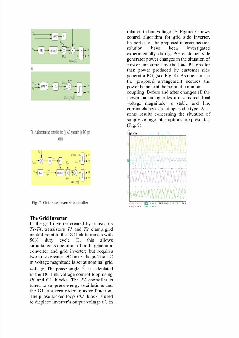
The Generator Converter:
Transistors T5, T6 create a two-quadrant
current type converter; they are switched
opposite each other. The control strategy isdetermined by generator type, however for
both generator types (DC as well as AC)
the value of the delivered energy is
determined by the generator current iG
forced in closed loop. The value of this
current is calculated in the maximum
power point tracking MPPT block which
allows optimal generator utilization. The
main difference between DC and AC
generators is in shaping of the generator
current iG which has to be the same shape
as the generated voltage. This is so
because in variable speed generators there
are strong dependencies between the
output voltage parameters (magnitude and
frequency) and speed of the shaft. Figure 6
shows proposed control strategies for both
generator types.
8/4/2019 A NEW TREND IN IMPROVING EFFICIENCY OF TRANSMISSION LINES IN
http://slidepdf.com/reader/full/a-new-trend-in-improving-efficiency-of-transmission-lines-in 7/8
The Grid Inverter
In the grid inverter created by transistors
T1-T4, transistors T1 and T2 clamp grid
neutral point to the DC link terminals with50% duty cycle D, this allows
simultaneous operation of both: generator
converter and grid inverter; but requires
two times greater DC link voltage. The UC
m voltage magnitude is set at nominal grid
voltage. The phase angle is calculated
in the DC link voltage control loop using
PI and G1 blocks. The PI controller is
tuned to suppress energy oscillations and
the G1 is a zero order transfer function.
The phase locked loop PLL block is usedto displace inverter’s output voltage uC in
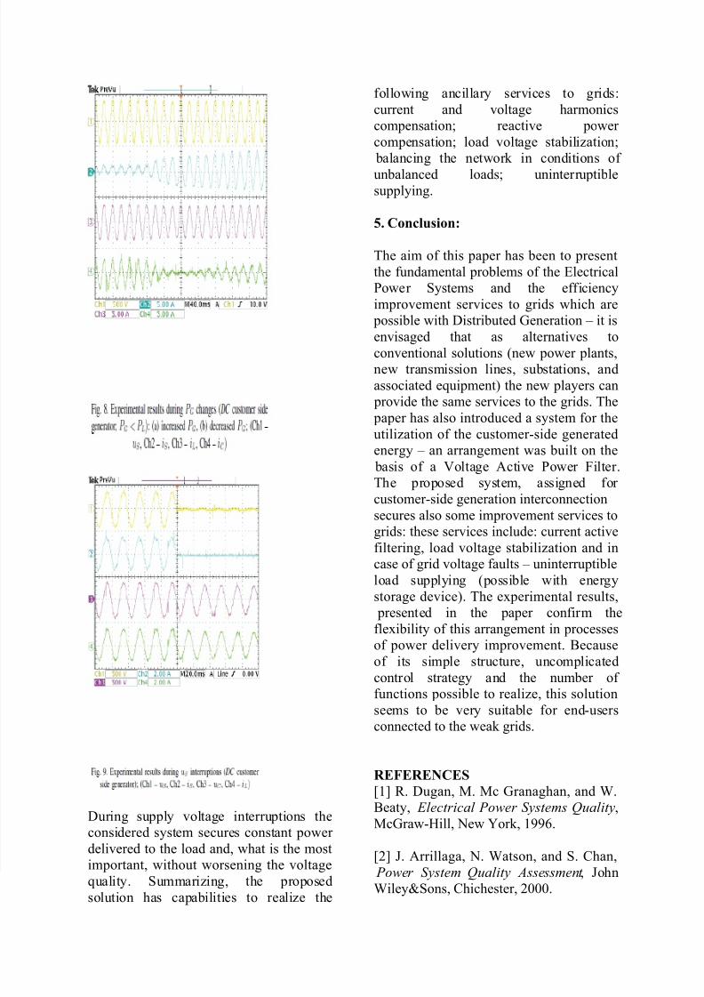
relation to line voltage uS. Figure 7 shows
control algorithm for grid side inverter.
Properties of the proposed interconnection
solution have been investigated
experimentally during PG customer side
generator power changes in the situation of power consumed by the load PL greater
than power produced by customer side
generator PG, (see Fig. 8). As one can see
the proposed arrangement secures the
power balance at the point of common
coupling. Before and after changes all the
power balancing rules are satisfied, load
voltage magnitude is stable and line
current changes are of aperiodic type. Also
some results concerning the situation of
supply voltage interruptions are presented(Fig. 9).
8/4/2019 A NEW TREND IN IMPROVING EFFICIENCY OF TRANSMISSION LINES IN
http://slidepdf.com/reader/full/a-new-trend-in-improving-efficiency-of-transmission-lines-in 8/8
During supply voltage interruptions the
considered system secures constant power
delivered to the load and, what is the most
important, without worsening the voltage
quality. Summarizing, the proposed
solution has capabilities to realize the
following ancillary services to grids:
current and voltage harmonics
compensation; reactive power
compensation; load voltage stabilization;
balancing the network in conditions of
unbalanced loads; uninterruptiblesupplying.
5. Conclusion:
The aim of this paper has been to present
the fundamental problems of the Electrical
Power Systems and the efficiency
improvement services to grids which are
possible with Distributed Generation – it is
envisaged that as alternatives to
conventional solutions (new power plants,new transmission lines, substations, and
associated equipment) the new players can
provide the same services to the grids. The
paper has also introduced a system for the
utilization of the customer-side generated
energy – an arrangement was built on the
basis of a Voltage Active Power Filter.
The proposed system, assigned for
customer-side generation interconnection
secures also some improvement services to
grids: these services include: current active
filtering, load voltage stabilization and in
case of grid voltage faults – uninterruptible
load supplying (possible with energy
storage device). The experimental results,
presented in the paper confirm the
flexibility of this arrangement in processes
of power delivery improvement. Because
of its simple structure, uncomplicated
control strategy and the number of
functions possible to realize, this solutionseems to be very suitable for end-users
connected to the weak grids.
REFERENCES
[1] R. Dugan, M. Mc Granaghan, and W.
Beaty, Electrical Power Systems Quality,
McGraw-Hill, New York, 1996.
[2] J. Arrillaga, N. Watson, and S. Chan,
Power System Quality Assessment , JohnWiley&Sons, Chichester, 2000.