Embed Size (px)
Citation preview
A note on the relationship between Petroleum Fields in the Bowen and Surat Basins and the Possible Implications
for the Migration of Injected Carbon Dioxide
Jacques Sayers June 2005
CO2CRC Report No: RPT05-0025
A note on the relationship between Petroleum Fields in the Bowen and Surat Basins and the Possible Implications
for the Migration of Injected Carbon Dioxide.
Jacques Sayers June 2005
CO2CRC Report No: RPT05-0025
Innovative Carbon Technologies Pty Ltd
PO Box 1130, Bentley, Western Australia 6102Phone: +61 8 6436 8655Fax: +61 8 6436 8555Email: [email protected]: www.ictpl.com.au
Reference: Sayers, J, 2005. A note on the relationship between Petroleum Fields in the Bowen and Surat Basins and the Possible Implications for the Migration of Injected Carbon Dioxide. CO2CRC/Geoscience Australia, Canberra, Australia, June 2005. CO2CRC Report Number RPT05-0025.
© ICTPL 2005
Unless otherwise specifi ed, Innovative Carbon Technologies Pty Ltd (ICTPL) retains copyright over this publication. You must not reproduce, distribute, publish, copy, transfer or commercially exploit any information contained in this publication that would be an infringement of any copyright, patent, trademark, design or other intellectual property right.
Requests and inquiries concerning copyright should be addressed to the Commercial Manager, ICTPL, PO Box 1130, Bentley, Western Australia 6102. Telephone: +61 8 6436 8655
A note on the relationship between Petroleum Fields in the Bowen and
Surat Basins and the Possible Implications for the Migration of Injected Carbon Dioxide.
Jacques Sayers (Geoscience Australia)
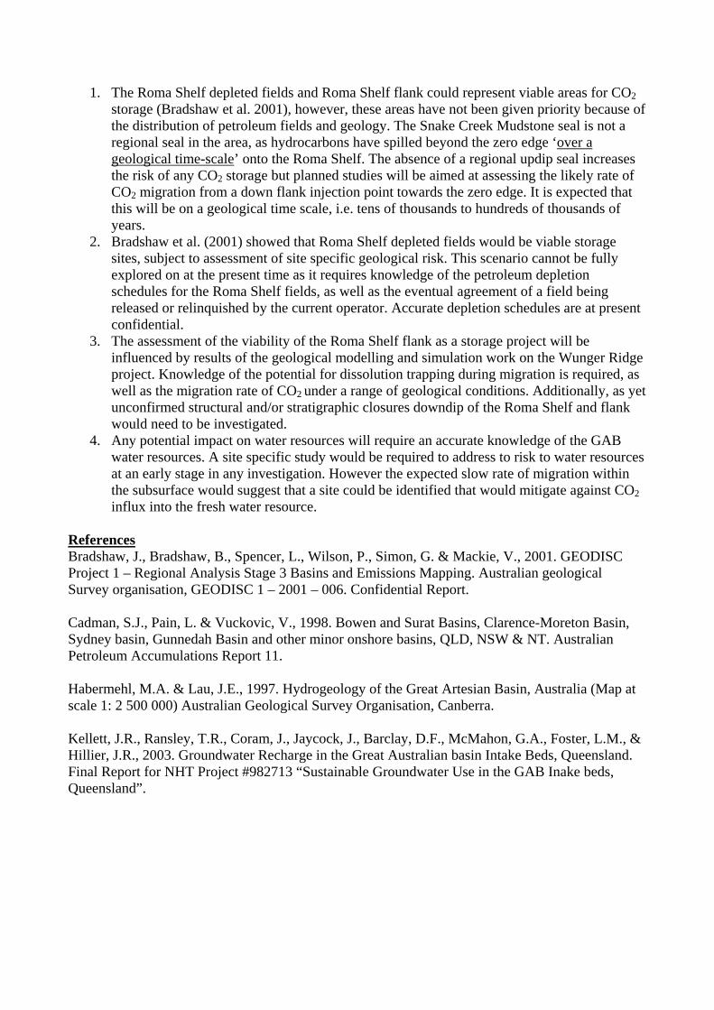
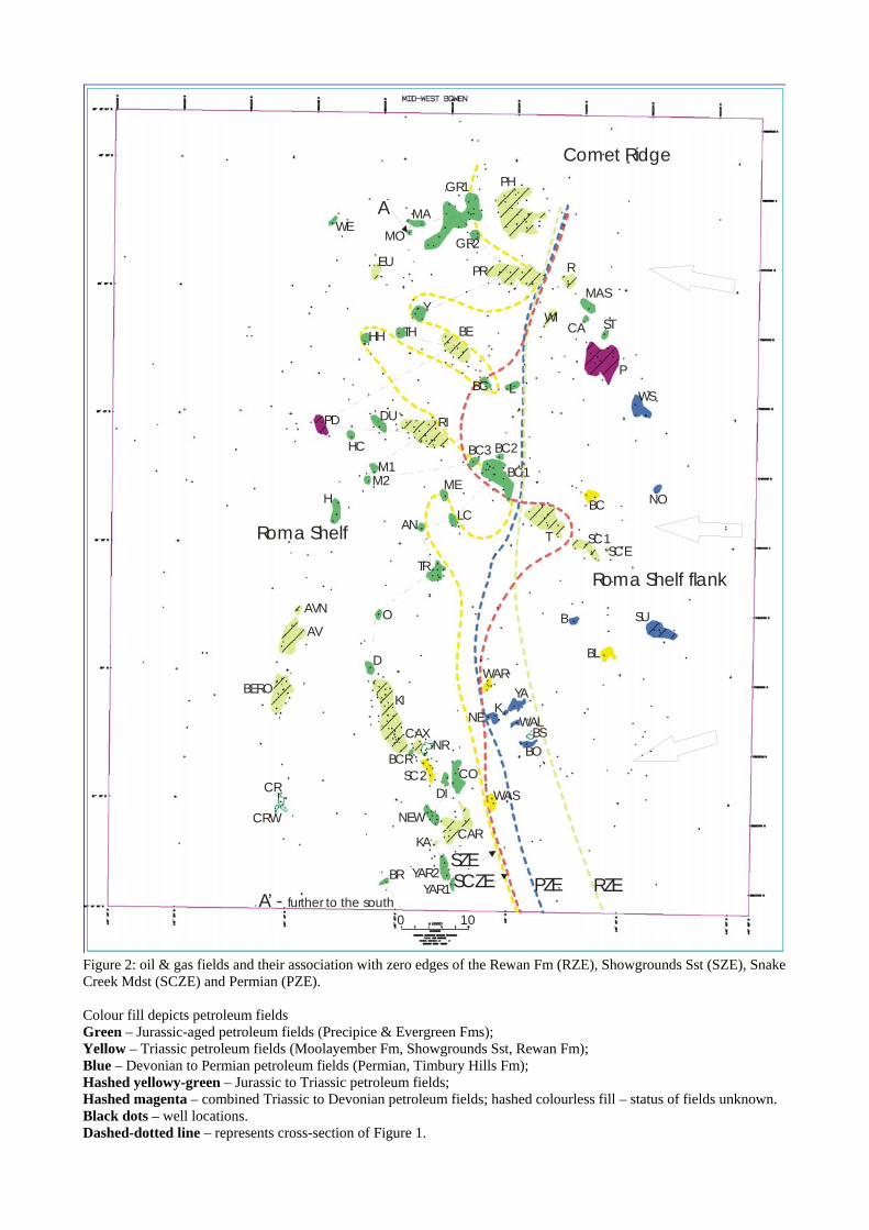
June 2005 Introduction The Roma Shelf and flank cover an area approximately 90 x 50 km in the mid-western part of the Bowen-Surat Basin. The Surat Basin is a post middle-Triassic basin that overlies the older post-early Permian Bowen Basin. Both basins have accumulations of hydrocarbons and the Surat Basin is also a significant water resource in central Queensland – it is part of the Great Artesian Basin (GAB) that covers the greater part of SW Queensland. Any potential for the storage of carbon dioxide (CO2) has to be balanced with the ability to still access both petroleum and water resources. The water within the GAB is generally fresh but salinity content does vary – further details on water composition can be found in Kellett et al. (2003). The water in the underlying Bowen Basin is generally too salty for human consumption. Any proposal to store CO2 is therefore likely to be confined to this deeper, older basin. The aim of this report is to look at the risk that CO2 injected into structures in the Bowen Basin for storage, could possibly make its way into the aquifers of the overlying Surat Basin and compromise the fresh water resource. Figures provided in this review comprise: Fig. 1) shows the geological concept of injection and migration within the greater Roma Shelf area as well as the key representative formations; Fig.2) which shows distribution of petroleum fields in combination with the zero edges of key formations; and Fig. 3) shows the stratigraphic definition of the GAB as defined by Habermehl & Lau (1997). Geological observations An understanding of the migration of CO2 and its potential to interfere with fresh water resources can be obtained by understanding how petroleum has migrated through the sediments of the Bowen Basin in the past. This knowledge can be used to predict how CO2 that could be injected into these sediments for long term storage might move away from its injection point over time. The petroleum resources of both the Bowen and the Surat Basins are sourced from coals within the Permian rocks in the basal parts of the Bowen Basin. This means that it is possible for fluids moving through buoyancy, as both hydrocarbons and CO2 do, to move from the deeper Bowen Basin into the overlying Surat Basin. The movement of the hydrocarbons is illustrated on Fig.1. In the lower section of the table of geological formations on the right, the section from the Permian source rock to the Snake Creek Mudstone is in the Bowen Basin, and the upper part of the section from the lower Precipice Sandstone to the top of the Evergreen Formation is the Surat Basin.
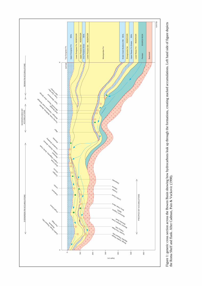
Hydrocarbons generated in the Permian source rocks at the lower right of the cross-section rise through the reservoir rock until they meet an impermeable layer, the seal. They will then move laterally updip along the base of the sealing formation, (Upper Rewan Fm shales) filling up and then spilling out of any closed structures that they encounter, until the seal “pinches out” laterally. At this point the hydrocarbons are able once again able to move vertically until they reach the next sealing surface (the Snake Creek Mudstone). Here they continue to move laterally until this unit also “pinches out”, when the hydrocarbons can move vertically into traps within the Precipice and Evergreen Sandstones of the Surat Basin. The important points to note are that firstly there must be sufficient hydrocarbons generated to fill the traps in the Bowen Basin before they can spill and enter the Surat Basin traps, and secondly where the sealing units of the Bowen Basin are competent; hydrocarbons are not found in the overlying Surat Basin, but where these sealing units are absent they are able to migrate upwards. A further point that must be made is that in some areas the Bowen Basin seals onlap onto basement highs, forming stratigraphic traps that will prevent the passage of hydrocarbons into the overlying units. If CO2 were to be injected into the reservoirs of the Bowen Basin, it would be expected to behave in a similar manner and not be able to enter the Surat Basin reservoirs until it had filled all the available space beneath the Bowen Basin seal. In addition to this there are other processes which will act upon the migrating CO2 that do not affect hydrocarbons. These, processes, which include dissolution of the CO2 into the formation water or trapping with formation of new minerals, will also remove the CO2 from the system. It is also expected than a significant percentage of the CO2 will be left behind as a residual phase permanently trapped within the pores of the rock. The volume of mobile CO2 will thus be substantially reduced over time. These secondary processes mean that if injected volumes are monitored correctly, then the migrating CO2 may never reach the edge of the seal even if the volumes injected were originally in excess of the capacity of the primary (structural) trapping mechanism. This discussion demonstrates how important the mapping of the zero (thickness) edges of the sealing units within the Bowen Basin is in understanding the potential behaviour of CO2 stored in the Bowen Basin. Figure 2 shows the location of the known oil and gas fields to these zero edges and demonstrates the relationships described above. For example, the distribution of Permian to Jurassic-reservoired petroleum fields in relation to the zero edges of the Permian formations,(Rewan Fm, Showgrounds Sst, and Snake Creek Mudstone (Fig. 1)) has implications both in understanding the way in which the fields filled as well as the interaction between migrating petroleum and water resources of the GAB, i.e.:
1) The zero edge of the Showgrounds Sst, the potential reservoir for CO2 storage, is located westward of the overlying sealing unit (Snake Creek Mudstone), and consequently any migrating fluids would probably not be trapped, at least on a semi-regional scale within this unit. (Figure 1) shows how hydrocarbons may have leaked onto the Roma Shelf. This stratigraphic relationship and the distribution of the units also demonstrates, at least partly, why a large portion of the fields on the Roma Shelf have hydrocarbons reservoired in the younger Jurassic units such as the Precipice and Evergreen Fms (Fig. 1, Table 1). This has clear implications for CO2 storage downdip of the Roma Shelf and flank if the CO2 is not able to be trapped en-route in minor rollovers or by dissolution trapping before spilling into the Jurassic reservoirs. This uncertainty should, however, be balanced with a consideration of the rate at which CO2 migrates (discussed later).
2) Figure 2 shows that a number of fields are located en-trend on NW-SE azimuths, suggesting that these fields may be fault-controlled structures where faults could act as conduits for fluids, petroleum or otherwise from the deeper section. Again this uncertainty is an additional risk for CO2 storage. This should, however, be balanced with knowledge of the rate at which CO2 migrates (discussed later).
3) Fields that are located eastward of the zero edges demonstrate that petroleum is trapped along the migration pathway and that not all migrates towards the Roma Shelf proper. The potential for undiscovered oil pools on the greater Roma Shelf Flank may restrict the potential for CO2 storage due to continuing exploration interest in this area.
4) One storage option for CO2 could be the injection of the super-critical fluid downdip in the Showgrounds Sandstone reservoir (Fig. 1), with the expectation that it will migrate westwards towards the Roma Shelf flank (Fig. 1). The concept being that the slowly migrating CO2 would be trapped en-route by dissolution, mineralisation and residual gas saturation as it moved laterally beneath the overlying Snake Creek Mudstone. The risk in this model would be that the volumes that could be trapped en route must be carefully monitored to avoid the spillage into the overlying Surat Basin that has been seen with migrating hydrocarbons.
Implications for water resources As both petroleum and water are extracted from the Surat Basin of the Roma Shelf area, the water resources must be subjected to water quality monitoring for potential contaminants such as petroleum or excessive salinity levels. Consequently, care would be needed to not further complicate water usage by proposing to store storing CO2 in the areas where the water resource is also being utilised (e.g. depleted oil fields located within the vicinity of the Roma township). Other storage solution concepts that could apply on of the Roma Shelf and flank; include en-route migration trapping , and dissolution trapping. Structural and/or stratigraphic closures would also need to be defined in the area. The research presently being carried out on the Wunger Ridge, an area 60 km to the SSE of the Roma Shelf, will provide information on migration rates of CO2, en-route migration and dissolution trapping, as well as the CO2/rock response within the geological sequences. The geology of the Wunger Ridge is similar to the geology on the Roma Shelf and flank, and as such, the knowledge-base gleaned from modelling and simulation results there can be transferred to the greater Roma Shelf area. The Wunger Ridge proper does not appear to have had hydrocarbons leaking up through the seal into the GAB and as such appears more attractive as a potential site. The risk to any water resource is ‘local site-specific’ as it is not known at this stage at what rate CO2 migrates within the range of typical reservoirs in this area. This migration will be controlled by rock properties such as permeability, porosity, facies, and bed thickness. In the Roma Shelf flank area CO2 being injected in one sand facies in one area may only migrate a few hundred meters and be of no consequence to water resources several kilometres away. Alternatively, a highly permeable (multi-Darcy) sheet-like sand would be less restrictive to fluid flow and allow the CO2 to migrate much further. Assessing the risk to water resources needs to be done on a case-by-case basis. Accurate information on water resources is not easily available as this data is held by multiple Government and private bodies. Water is considered a resource with legally-binding ownership rights to individuals and private companies. Conclusions Research linked to these studies is still on-going as part of the core programme of the CO2CRC and any conclusions are provisional and represent work in progress which may be revised in the coming months.
1. The Roma Shelf depleted fields and Roma Shelf flank could represent viable areas for CO2
storage (Bradshaw et al. 2001), however, these areas have not been given priority because of the distribution of petroleum fields and geology. The Snake Creek Mudstone seal is not a regional seal in the area, as hydrocarbons have spilled beyond the zero edge ‘over a geological time-scale’ onto the Roma Shelf. The absence of a regional updip seal increases the risk of any CO2 storage but planned studies will be aimed at assessing the likely rate of CO2 migration from a down flank injection point towards the zero edge. It is expected that this will be on a geological time scale, i.e. tens of thousands to hundreds of thousands of years.
2. Bradshaw et al. (2001) showed that Roma Shelf depleted fields would be viable storage sites, subject to assessment of site specific geological risk. This scenario cannot be fully explored on at the present time as it requires knowledge of the petroleum depletion schedules for the Roma Shelf fields, as well as the eventual agreement of a field being released or relinquished by the current operator. Accurate depletion schedules are at present confidential.
3. The assessment of the viability of the Roma Shelf flank as a storage project will be influenced by results of the geological modelling and simulation work on the Wunger Ridge project. Knowledge of the potential for dissolution trapping during migration is required, as well as the migration rate of CO2 under a range of geological conditions. Additionally, as yet unconfirmed structural and/or stratigraphic closures downdip of the Roma Shelf and flank would need to be investigated.
4. Any potential impact on water resources will require an accurate knowledge of the GAB water resources. A site specific study would be required to address to risk to water resources at an early stage in any investigation. However the expected slow rate of migration within the subsurface would suggest that a site could be identified that would mitigate against CO2 influx into the fresh water resource.
References Bradshaw, J., Bradshaw, B., Spencer, L., Wilson, P., Simon, G. & Mackie, V., 2001. GEODISC Project 1 – Regional Analysis Stage 3 Basins and Emissions Mapping. Australian geological Survey organisation, GEODISC 1 – 2001 – 006. Confidential Report. Cadman, S.J., Pain, L. & Vuckovic, V., 1998. Bowen and Surat Basins, Clarence-Moreton Basin, Sydney basin, Gunnedah Basin and other minor onshore basins, QLD, NSW & NT. Australian Petroleum Accumulations Report 11. Habermehl, M.A. & Lau, J.E., 1997. Hydrogeology of the Great Artesian Basin, Australia (Map at scale 1: 2 500 000) Australian Geological Survey Organisation, Canberra. Kellett, J.R., Ransley, T.R., Coram, J., Jaycock, J., Barclay, D.F., McMahon, G.A., Foster, L.M., & Hillier, J.R., 2003. Groundwater Recharge in the Great Australian basin Intake Beds, Queensland. Final Report for NHT Project #982713 “Sustainable Groundwater Use in the GAB Inake beds, Queensland”.
Figu
re 1
: gen
eric
cro
ss se
ctio
n ac
ross
the
Bow
en B
asin
show
ing
how
hyd
roca
rbon
s lea
k up
thro
ugh
the
form
atio
ns, c
reat
ing
stac
ked
accu
mul
atio
ns. L
eft h
and
side
of f
igur
e de
pict
s th
e R
oma
Shel
f and
flan
k. A
fter C
adm
an, P
ain
& V
ucko
vic
(199
8).
Low
er E
verg
reen
Fm
RE
SE
RV
OIR
Moo
laye
mbe
r F
m
Bas
emen
t
Upp
er E
verg
reen
Fm
SE
AL
Upp
er P
reci
pice
Sst
R
ES
ER
VO
IR
Intr
a-P
reci
pice
Sha
le
S
EA
L
Low
er P
reci
pice
Sst
R
ES
ER
VO
IR
Sna
ke C
reek
Mud
ston
e M
br
SE
AL
Sho
wgr
ound
s S
st
R
ES
ER
VO
IR
Upp
er R
ewan
Fm
Sha
les
SE
AL
Low
er R
ewan
Fm
RE
SE
RV
OIR
600
500
400
300
200
1000
12/A
/183
Yanalah, Pine Ridge,
Timbury Hills
Mooga, Grafton Range,
Mayfield, Pleasant H
ills
Beaufort, Damper C
reek,
Warooby South
Richmond, Colgoon,
Maffra Bony Creek, Merrit
Lyndon Caves
Trinidad Oberina
Deepwater
PR
EC
IPIC
E S
ST
AC
CU
MU
LAT
ION
S
Grafto
n Ran
ge, P
leasa
nt H
ills,
Wes
tland
s
Pine R
idge
Pringle
Dow
ns
Anabr
anch
Land
or
Cardig
an Kincor
a
Borah
Cre
ek
Newste
ad Carbe
an, K
analo
o, B
erwick
Yarra
bend
, Bro
adway
Rivers
lea
Majo
r
Thorn
by C
reek
, McW
hirte
r, Ben
dee
North
Box
leigh
Mer
room
bil, R
oswin,
Silv
er S
pring
s
Taylor
, Bee
chwoo
d
Tinker
, Eas
t Glen
EV
ER
GR
EE
N F
M A
CC
UM
ULA
TIO
NS
SH
OW
GR
OU
ND
S S
ST
AC
CU
MU
LAT
ION
S
Top
Eve
rgre
en F
mD
AT
UM
A’
A
Depth (m)
Colgoo
n, D
idger
idoo,
San
dy C
reek
McG
rego
r, Yell
owba
nk C
reek
, Box
leigh
Glen F
ossly
n
RE
WA
N F
M A
CC
UM
ULA
TIO
NS
Per
mia
n
SO
UR
CE
RO
CK
0 10
SZERZEPZESCZE
Roma Shelf
Comet Ridge
Roma Shelf flank
HH TH
WEMO
EU
Y
GR2
MA
BE
LP
WS
PHGR1
BC
ST
PD
WAS
DU RI
WICA
MAS
RPR
BC1
T SC1SCE
BC NOLC
ME
BC3 BC2
O
TR
HM2M1
B
WAR
AN
AV
YA
SUAVN
NE WAL
BL
KI K
DICOSC2
BCRNR
CAX
CRW
CR
BERO
BRYAR1
YAR2
CAR
D
KA
NEW
BOBS
HC
A
A’ - further to the south
Figure 2: oil & gas fields and their association with zero edges of the Rewan Fm (RZE), Showgrounds Sst (SZE), Snake Creek Mdst (SCZE) and Permian (PZE). Colour fill depicts petroleum fields Green – Jurassic-aged petroleum fields (Precipice & Evergreen Fms); Yellow – Triassic petroleum fields (Moolayember Fm, Showgrounds Sst, Rewan Fm); Blue – Devonian to Permian petroleum fields (Permian, Timbury Hills Fm); Hashed yellowy-green – Jurassic to Triassic petroleum fields; Hashed magenta – combined Triassic to Devonian petroleum fields; hashed colourless fill – status of fields unknown. Black dots – well locations. Dashed-dotted line – represents cross-section of Figure 1.
FFi
gure
3: s
tratig
raph
ic d
efin
ition
of t
he G
reat
Arte
sian
bas
in, a
s def
ined
by
Hab
erm
ehl &
Lau
(199
7). N
ote
that
som
e of
the
form
atio
ns a
re a
lso
petro
leum
-bea
ring
form
atio
ns.