Embed Size (px)
Citation preview

TELKOMNIKA Indonesian Journal of Electrical EngineeringVol. 15, No. 3, September 2015, pp. 486 ~ 496DOI: 10.11591/telkomnika.v15i3.8435 486
Received November 2, 2014; Revised January 26 2015; Accepted February 15, 2015
A Novel Approach for Design and Analysis of Voltage-Controlled DSTATCOM for Power Quality Enhancement
Syed Ruman, Shaik HameedQuba College of Engg & Tech., Andhra Pradesh 524320, India
email: [email protected]
AbstractThe power fluctuations affect the quality of power supplied by the distributed power system. The
Power quality fluctuations of the distributed power system show a serious impact on the robust andsustainable operation of the distributed power system. These power quality fluctuations may be causeddue to several reasons like leakage, faults and ageing of the lines. This project proposes a new algorithmto generate reference voltage for a controlled mode distribution static compensator (DSTATCOM)operating in voltage-control mode. The proposed scheme exhibits several advantages compared totraditional voltage-controlled DSTATCOM where the reference voltage is arbitrarily taken as 1.0 p.u. Theproposed scheme ensures that unity power factor (UPF) is achieved, while regulating the voltage at theload terminal, during load change, which is not possible in the traditional method. Also, the compensatorinjects lower currents and, therefore, reduces losses in the feeder and voltage-source inverter. Further, asaving in the rating of DSTATCOM is achieved to increases its capacity to mitigate voltage sag. The state-space model of DSTATCOM is incorporated with the deadbeat predictive controller for fast load voltageregulation during voltage disturbances. With these features, this scheme allows DSTATCOM to tacklepower-quality issues by providing power factor correction, harmonic elimination, load balancing, andvoltage regulation based on the load requirement. Simulation and experimental results are presented todemonstrate the efficacy of the proposed algorithm.
Copyright © 2015 Institute of Advanced Engineering and Science. All rights reserved.
1. IntroductionA Distribution power system suffers from current as well as voltage-related power-quality
(PQ) problems, which include poor power factor, distorted source current, and voltagedisturbances [1, 2]. A DSTATCOM, connected at the point of common coupling (PCC), has beenutilized to mitigate both types of PQ problems [2-12]. When operating in current control mode(CCM), it injects reactive and harmonic components of load currents to make source currentsbalanced, sinusoidal, and in phase with the PCC voltages [3-7]. In voltage-control mode (VCM)[2], [8-12], the DSTATCOM regulates PCC voltage at a reference value to protect critical loadsfrom voltage disturbances, such as sag, swell, and unbalances. However, the advantages ofCCM and VCM cannot be achieved simultaneously with one active filter device, since two modesare independent of each other.
In CCM operation, the DSTATCOM cannot compensate for voltage disturbances.Hence, CCM operation of DSTATCOM is not useful under voltage disturbances, which is amajor disadvantage of this mode of operation [13]. Traditionally, in VCM operation, theDSTATCOM regulates the PCC voltage at 1.0 p.u. [2], [8-11]. However, a load workssatisfactorily for a permissible voltage range [14]. Hence, it is not necessary to regulate the PCCvoltage at 1.0 p.u. While maintaining 1.0-p.u. voltage, DSTATCOM compensates for the voltagedrop in feeder. For this, the compensator has to supply an additional reactive current whichincreases the source currents. This increases losses in the voltage-source inverter (VSI) andfeeder. Another important aspect is the rating of the VSI. Due to increased current injection, theVSI is de-rated in steady-state condition. Consequently, its capability to mitigate deep voltagesag decreases. Also, UPF cannot be achieved when the PCC voltage is 1p.u. In the literature,so far, the operation of DSTATCOM is not reported where the advantages of both modes areachieved based on load requirements while overcoming their demerits.
This paper considers the operation of DSTATCOM in VCM and proposes a controlalgorithm to obtain the reference load terminal voltage. This algorithm provides the combinedadvantages of CCM and VCM. The UPF operation at the PCC is achieved at nominal load,

TELKOMNIKA ISSN: 2302-4046
A Novel Approach for Design and Analysis of Voltage-Controlled DSTATCOM… (Syed Ruman)
487
whereas fast voltage regulation is provided during voltage disturbances. Also, the reactive andharmonic component of load current is supplied by the compensator at any time of operation.The deadbeat predictive controller [15-17] is used to generate switching pulses. The controlstrategy is tested with a three-phase four-wire distribution system. The effectiveness of theproposed algorithm is validated through detailed simulation and experimental results.
2. Proposed MethodPower regulation in a Distributed Power System (DPS) is a trival and most important
task, which affects the quality of power being supplied from the DPS. The power and voltagelevels from the DPS may get disturbed by several factors like line impedance variations due toageing of the line, increased heat during summer, unnecessary snow and rain fall, corrosion,thunders and storms. But all the applications which rely for their operation on electrical powerfrom the DPS required the power to be supplied at the required rated level. The power quality ofthe Power Distribution Line Bus (PDLB) may get fluctuated due to a sudden variation in the loadimpedance, source current levels and input power fluctuations. Whatever it may be the reasonfor power fluctuation, but the utilities of electrical energy from the DPS cannot continue normaloperation, there by demanding regulated rated power quality for lossless and destruction lessoperation of their internal discrete components. Thus regulations of power levels from the DPSare the most important task and to perform that task, several methods were proposed in theliterature. But among them we found that the Distributed STATic COMpensator is best inperformance in all aspects compared to all other existing techniques. Since from the operationalknowledge of the DSTATCOM we found that, the salient performance features of DSTATCOMare steered by the proper selection of appropriate threshould/reference voltage. TheDSTATCOM offers best of its performance if the reference voltage was selected appropriately,otherwise its performance may not be satisfactory. Hence proper selection of reference voltagefor the DSTATCOM decides the effectiveness of DSTATCOM in distributed power regulationactivities. In this project we are going to design the reference voltage for the DSTATCOM whichis designed and implemented using fuzzy logic and being operated in the control mode. TheCircuit diagram of a DSTATCOM -compensated distribution system is shown in Figure 1. It usesa three- phase, four-wire, two-level, neutral-point-clamped Voltage Switching Inverter (VSI). Thisstructure allows independent control to each leg of the VSI [7]. Figure 2 shows the single-phaseequivalent representation of Figure 1. Variable ‘ ’ is a switching function, and can be eitheror -1 depending upon switching state. Filter inductance and resistance are and ,respectively. Shunt capacitor eliminates high-switching frequency components.
Figure 1. Circuit diagram of the DSTATCOM-compensated distribution system
Figure 2. Single-phase equivalent circuit ofDSTATCOM
First, discrete modeling of the system is presented to obtain a discrete voltage controllaw, and it is shown that the PCC voltage can be regulated to the desired value with properlychosen parameters of VSI. Then, a procedure to design VSI parameters is presented. Aproportional-integral (PI) controller is used to regulate the dc capacitor voltage at a reference

ISSN: 2302-4046
TELKOMNIKA Vol. 15, No. 3, September 2015 : 486 – 496
488
value. Based on instantaneous symmetrical component theory and complex Fourier transform,a reference voltage magnitude generation scheme is proposed that provides the advantages ofCCM at nominal load. The overall controller block diagram is shown in Figure 3.
Figure 3. Overall block diagram of the controller to control DSTATCOM in a distribution system
The state-space equations for the circuit shown in Figure 2 are given by:̇ = + (1)
Where,
= ⎣⎢⎢⎢⎡ 0 000 ⎦⎥⎥
⎥⎤
= ⎣⎢⎢⎢⎡ 0 − 00 00 0 ⎦⎥⎥
⎥⎤x=[ ] ,z=[ ]The general time-domain solution of Equation (1) to compute the state vector x(t) with
known initial value x(t0) is given as follows:( ) = ( ) ( ) + ∫ ( ) ( ) (2)
The equivalent discrete solution of the continuous state is obtained by replacing t0=kTdand t=(k+1)Td as follows:( + 1) = ( ) + ∫ ( ) ( ) (3)
Where k and Td represents the kth sample and sampling period respectively. During theconsecutive sampling period, the value of z(τ) is held constant, and can be taken as z(k). Aftersimplification and changing the integration variable, Equation (3) can be written as:( + 1) = + ∫ ( ) (4)
This equation is rewritten as follows:

TELKOMNIKA ISSN: 2302-4046
A Novel Approach for Design and Analysis of Voltage-Controlled DSTATCOM… (Syed Ruman)
489
( + 1) = ( ) + ( ) (5)Where H and G are sampled matrices, with the sampling time of Td. For Small sampling time,matrices G and H are calculated as follows:
= = ≈ + + (6)
= = ∫ ≈ ∫ ( + ) . (7)
Hence the capacitor voltage is given as:( + 1) = ( ) + ( ) + ( ) + ( ) (8)
As seen from Equation (8), the terminal voltage can be maintained at a reference valuedepending upon the VSI parameters , , , and sampling time .Therefore, VSIparameters must be chosen carefully. Let ∗ be the reference load terminal voltage. A costfunction J is chosen as follows.= [ ( + 1) − ∗( + 1)] (9)
The cost function is differentiated with respect to u(k) and its minimum is obtained at:( + 1) = ∗( + 1) (10)
The deadbeat voltage-control law, from (8) and (10), is given as:
∗ = ∗( ) ( ) ( ) ( )(11)
The schematic overall block diagram of the proposed controller to control theDSTATCOM in distributed power system is shown in Figure 3, which consists of a zero crossingdetector which detects the zero crossing points in three phasor voltage waveforms. Using theresult from the zero crossing detector and load angle from the PI controller to maintain dccapacitor voltage, the Unit Vector Generator (UVG) generates three unit threshould vectors forthree phasor voltage lines of the DSTATCOM which will be further optimized according to thecharacteristic equation.
∗ = − (| ̅ | ) − | ̅ | (12)
The dead beat voltage controller regulates the voltage fluctuations in three Phasor linesin proportion to the feedback control phase sample inputs for three Phasor lines so as to controlthe cost of power quality regulation process according to the cost function conditionally steeredby functional and threshould voltages of three phasors lines of the DSTATCOM. Thus thediscrete functional units of DSTATCOM will work.
Reference terminal voltages are generated such that, at nominal load, all advantages ofCurrent Controlled Mode (CCM) operation are achieved while DSTATCOM is operating inVoltage Controlled Mode (VCM). Hence, the DSTATCOM will inject reactive and harmoniccomponents of load current. To achieve this, first the fundamental positive-sequencecomponent of load currents is computed. Then, it is assumed that these currents come from thesource and considered as reference source currents at nominal load. With these sourcecurrents and for UPF at the PCC, the magnitude of the PCC voltage is calculated. Let three-phase load currents. ( ), ( ) and ( ) be represented by the following equations.( ) = ∑ √2 sin ( + ∅ )
ISSN: 2302-4046
TELKOMNIKA Vol. 15, No. 3, September 2015 : 486 – 496
490
Where j=a, b, c represent three phases, ‘n’ is the harmonic number, and ‘m’ is the maximumharmonic order. ∅ represents the phase angle of the nth order harmonic with respect toreference in phase-a and is similar to other phases.
3. Results and DiscussionThe practical implementation of the proposed algorithm for generating the reference
voltage of the Distributive Static Compensator (DSTATCOM) operating in the control mode forvoltage stability control and analysis of a distributed power system is done by designing thecorresponding Simulink models hierarchically to replicate various processing stages involved indesigning the DSTATCOM and various processing models using MATLAB/SIMULINK software.The proposed algorithm will includes the design and analysis of various DSTATCOM models asgiven under.
Figure 4. Model before Compensation
The basic DSTATCOM model before compensating the spurious voltage fluctuations inthe phasor lines of the Distributed Power System (DPS) is shown in above Figure 4. This modelwill consists of a distributed Generation based power generation unit which supplies the powerto the load units through the three phase lines. The load unit can be either linear load unit ornon-linear load unit. The output voltage levels will be displayed on the Oscilloscopes.
Figure 5. Terminal Voltage waveforms of threephasor lines of the DSTATCOM before
compensation
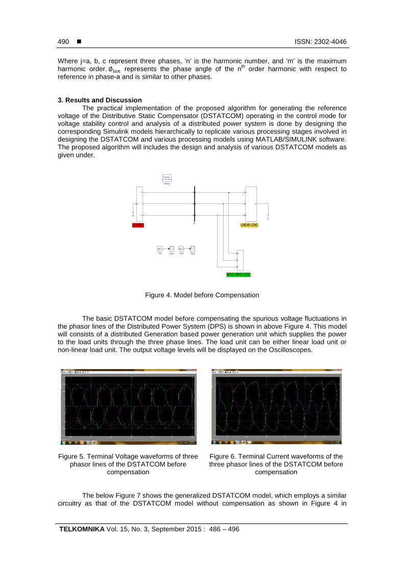
Figure 6. Terminal Current waveforms of thethree phasor lines of the DSTATCOM before
compensation
The below Figure 7 shows the generalized DSTATCOM model, which employs a similarcircuitry as that of the DSTATCOM model without compensation as shown in Figure 4 in
LINEAR LOAD
NON LINEAR LOAD
SOURCE
Discrete,Ts = 5e-005 s.
powergui
N
R
Y
B
R
Y
B
R
Y
B
N
Iabc_1
From2
Vabc_1
From Fig 4bFig 4a
A
B
C
a
b
c
B1

TELKOMNIKA ISSN: 2302-4046
A Novel Approach for Design and Analysis of Voltage-Controlled DSTATCOM… (Syed Ruman)
491
addition with a compensation circuitry to compensate the voltage fluctuations in the phasor linesof the power distribution system.
Figure 7. Generalized DSTATCOM Model
Figure 8. Measured Voltage at the terminals ofthe generalized DSTATCOM
Figure 9. Terminal voltage and currents of aphasor line of generalized DSTATCOM model
Figure 10. RMS Compensator current ofgeneralized DSTATCOM
Figure 11. VSC active power waveform of thegeneralized DSTATCOM
LINEAR LOAD
NON LINEAR LOAD
SOURCE
Discrete,Ts = 5e-005 s.
powergui
v+-
Voltage Measurement
Subsystem4
R
B
Y
N
N
R
Y
B
R
Y
B
R
Y
B
N
Scope
A
B
C
a
b
c
B3
A
B
C
a
b
c
B2
A
B
C
a
b
c
B1
ISSN: 2302-4046
TELKOMNIKA Vol. 15, No. 3, September 2015 : 486 – 496
492
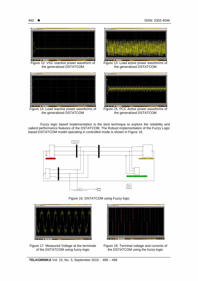
Figure 12. VSC reactive power waveform ofthe generalized DSTATCOM
Figure 13. Load active power waveforms ofthe generalized DSTATCOM
Figure 14. Load reactive power waveforms ofthe generalized DSTATCOM
Figure 15. PCC Active power waveforms ofthe generalized DSTATCOM
Fuzzy logic based implementation is the best technique to explore the reliability andsalient performance features of the DSTATCOM. The Robust implementation of the Fuzzy Logicbased DSTATCOM model operating in controlled mode is shown in Figure 16.
Figure 16. DSTATCOM using Fuzzy logic
Figure 17. Measured Voltage at the terminalsof the DSTATCOM using fuzzy-logic
Figure 18. Terminal voltage and currents ofthe DSTATCOM using the fuzzy-logic
LINEAR LOAD
NON LINEAR LOAD
SOURCE
Discrete,Ts = 5e-005 s.
powergui
v+-
Voltage Measurement
Subsystem4
R
B
Y
N
N
R
Y
B
R
Y
B
R
Y
B
N
Scope
A
B
C
a
b
c
B3
A
B
C
a
b
c
B2
A
B
C
a
b
c
B1

TELKOMNIKA ISSN: 2302-4046
A Novel Approach for Design and Analysis of Voltage-Controlled DSTATCOM… (Syed Ruman)
493
Figure 19. Terminal voltages of the threephasor lines of the DSTATCOM using the
Fuzzy-Logic
Figure 20. Terminal currents of theDSTATCOM system using the Fuzzy-Logic
Figure 21. Source voltage waveforms of thethree phasor lines of the DSTATCOM using
Fuzzy-Logic
Figure 22. Source current waveforms of thethree phasor lines of the DSTATCOM using
the Fuzzy-Logic
Figure 23. RMS source current waveform ofthe DSTATCOM using the Fuzzy-Logic
Figure 24. RMS Compensation current of theDSTATCOM using Fuzzy-Logic
Figure 25. VSC Active power of theDSTATCOM using Fuzzy–Logic
Figure 26. VSC reactive power of theDSTATCOM using the Fuzzy-Logic

ISSN: 2302-4046
TELKOMNIKA Vol. 15, No. 3, September 2015 : 486 – 496
494
Figure 27. Load active power of theDSTATCOM using the Fuzzy-Logic
Figure 28. Load reactive power of theDSTATCOM using the Fuzzy-Logic
Figure 29. PCC active power of theDSTATCOM using the Fuzzy logic
Figure 30. PCC reactive power of theDSTATCOM using the Fuzzy-Logic
Figure 31. DSTATCOM with lo Figure 32. Terminal voltage fluctuations of thethree phasor lines of the DSTATCOM with lo
Figure 33. DSTATCOM with SA Figure 34. Terminal voltages of theDSTATCOM with line sag modeling using the
threshould technique

TELKOMNIKA ISSN: 2302-4046
A Novel Approach for Design and Analysis of Voltage-Controlled DSTATCOM… (Syed Ruman)
495
4. ConclusionIn this paper, we proposed a control algorithm for the generation of reference load
voltage for a voltage-controlled DSTATCOM being operated in a control mode. Theperformance of the proposed scheme is compared with the traditional voltage-controlledDSTATCOM. The proposed method provides the following advantages at nominal load; (a) Thecompensator injects reactive and harmonic components of load currents, resulting in an UPF;(b) Nearly UPF is maintained for a load change; (c) Fast voltage regulation has been achievedduring voltage disturbances; (d) Losses in the VSI; (e) Feeders are reduced considerably, andhave higher sag supporting capability with the same VSI rating compared to the traditionalscheme. The simulation and experimental results show that the proposed scheme providesDSTATCOM, a capability to improve several PQ problems (related to voltage and current).
5. Future ScopeEven though the Distributed STATic COMpensator is proven to be the best in all
aspects compared to all other existing techniques. The salient performance features ofDSTATCOM are steered by the proper selection of appropriate threshould/reference voltage.The DSTATCOM offers best of its performance if the reference voltage was selectedappropriately, otherwise its performance may not be satisfactory. Hence proper selection ofreference voltage for the DSTATCOM decides the effectiveness of DSTATCOM in distributedpower regulation activities. In this project we designed the reference voltage for theDSTATCOM which is designed and implemented using fuzzy logic and being operated in thecontrol mode. There is a huge scope to extend the work further to improve the operationaleffectiveness of the DSTATCOM operating in the control mode by just optimizing thethreshold/reference voltage designed for DSTATCOM.Reference voltage optimization enablesthe control voltage design to be appropriate which enables the DSTATCOM to deliver best of itsperformance.
References:[1] M Bollen. Understanding Power Quality Problems. IEEE. Piscataway, NJ, USA. 2000; 1: 1-35.[2] H Fujita, H Akagi. Voltage-regulation performance of a shunt active filter intended for installation on a
power distribution system. IEEE Trans. Power Electron. 2007; 22(3): 1046-1053.[3] A Ghosh, G Ledwich. Load compensating DSTATCOM in weak ac systems. IEEE Trans Power Del.
2003; 18(4): 1302-1309.[4] A Elnady, M Salama. Unified approach for mitigating voltage sag and voltageflicker using the
DSTATCOM. IEEE Trans Power Del. 2006; 20(2): 992-1000.[5] S Rahmani, A Hamadi, K Al-Haddad. A Lyapunov-function based control for a three-phase shunt
hybrid activefilter. IEEE Trans Ind Electron. 2012; 59(3): 1418-1429.[6] MK Mishra, K Karthikeyan. A fast-acting dc-link voltage controller for three-phase DSTATCOM to
compensate ac and dc loads. IEEE Trans Power Del. 2009; 24(4): 2291-2299.[7] MK Mishra, A Ghosh, A Joshi, HM Suryawanshi. A novel method of load compensation under
unbalanced and distorted voltages. IEEE Trans Power Del. 2007; 22(1): 288-295.[8] MK Mishra, A Ghosh, A Joshi. Operation of a DSTATCOM in voltage control mode. IEEE Trans Power
Del. 2003; 18(1): 258-264.[9] A Jain, K Joshi, A Behal, N Mohan. Voltage regulation with STATCOMs: Modeling, control and results.
IEEE Trans Power Del. 2006; 21(2): 726-735.[10] R Gupta, A Ghosh, A Joshi. Switching characterization of cascaded multilevel-inverter-controlled
systems. IEEE Trans Ind Electron. 2008; 55(3): 1047-1058.[11] P Mitra, G Venayagamoorthy. An adaptive control strategy for DSTATCOM applications in an electric
ship power systems. IEEE Trans Power Electron. 2010; 25(1): 95-104.[12] A Yazdani, M Crow, J Guo. An improved nonlinear STATCOM control for electric arc furnace voltage
flicker mitigation. IEEE Trans Power Del. 2009; 24(4): 2284-2290.[13] SH Ko, S Lee, H Dehbonei, C Nayar. Application of voltage and current-controlled voltage source
inverters for distributed generation systems. IEEE Trans Energy Convers. 2006; 21(3): 782-792.[14] M Moradlou, H Karshenas. Design strategy for optimum rating selection of interline DVR. IEEE Trans
Power Del. 2011; 26(1): 242-249.[15] J Rodriguez, J Pontt, CA Silva, P Correa, P Lezana, P Cortes, U Amman. Predictive current control of
a voltage source inverters. IEEE Trans Ind Electron. 2007; 54(1): 495-503.[16] J Barros, J Silva. Multilevel optimal predictive dynamic voltage restorer. IEEE Trans Ind Electron.
2010; 57(8): 2747-2760.

ISSN: 2302-4046
TELKOMNIKA Vol. 15, No. 3, September 2015 : 486 – 496
496
[17] O Kukrer. Discrete-time current control of voltage-fed three-phase PWM inverters. IEEE Trans PowerElectron. 1996; 11(2): 260-269.
[18] I Nagrath, M Gopal. Control Systems Engineering. NewYork, USA: Halsted. 1982: 518-519.[19] B Singh, P Jayaprakash, T Somayajulu, D Kothari. Reduced rating VSC with a zig-zag transformer for
current compensation in a three-phase four-wire distribution system. IEEE Trans Power Del. 2009;24(1): 249-259.