Embed Size (px)
Citation preview
A Novel Central Voltage-Control Strategy for Smart LVDistribution Networks
Efrain Bernal Alzate(✉), Qiang Li, and Jian Xie
Institute of Energy Conversion and Storage, University of Ulm, Ulm, [email protected], [email protected], [email protected]
Abstract. With the inclusion of Information and Communication Technology(ICT) components into the low-voltage (LV) distribution grid, some measurementdata from smart meters are available for the control of the distribution networkswith high penetration of photovoltaic (PV). This paper undertakes a centralvoltage-control strategy for smart LV distribution networks, by using a noveloptimal power flow (OPF) methodology in combination with the informationcollected from smart meters for the power flow calculation. The proposed strategycan simultaneously mitigate the PV reactive power fluctuations, as well as mini‐mize the voltage rise and power losses. The results are very promising, as voltagecontrol is achieved fast and accurately, the reactive power is smoothed in refer‐ence to the typical optimization techniques and the local control strategies asvalidated with a real-time simulator.
Keywords: Smart grid · Renewable energy integration · PV power forecasting ·Smart meter · Power system state estimation · LV distribution networks · ICT
1 Introduction
As the penetration of residential and commercial PV increases into electrical distributionsystems, an actual trend in the south of Germany, problems such as voltage rise, over‐loading of network equipment, harmonic current emissions, network resonance, falseislanding detection, and dc current injections are becoming more of an issue to beaddressed carefully [1]. Concrete solutions for secure and reliable integration of distrib‐uted PV generation into distribution systems are a fundamental concern for bothacademia [4, 6, 7] and industry [8, 19, 32].
A wide range of research projects have focused their efforts particularly on studyinghow to develop reverse power flow or voltage rise regulation methods to allow thisintegration. Conventional control mechanisms for distribution voltage regulation are:Voltage control on the feeder by using on-load tap-changing transformers (OLTC) [28,33, 34], and fixed or switched capacitors to offset the reactive power demand from theload and thus reduce the current flow through the feeder and the related voltage drop [5,19, 35]. The problem with OLTC transformers or voltage regulators is that, the amountof permissible voltage increase is limited if there is a load near the voltage regulator, acommon case in LV distribution networks, so additional voltage regulators along thefeeder may be necessary.
© Springer International Publishing Switzerland 2015W.L. Woon et al. (Eds.): DARE 2015, LNAI 9518, pp. 16–30, 2015.DOI: 10.1007/978-3-319-27430-0_2
On the other hand, it is also questionable whether the capacitor bank technology issufficient to answer these challenges, because it may require faster and more flexiblecontrol systems than the achievable with capacitor banks [35].
Another potential solution is the use of PV inverters’ reactive power as a promisinginexpensive concept to resolve the problems caused by PV penetration. Its developmentand realization attract research efforts in a fairly large number of issues ranging frommodeling [3, 8] to implementation [32, 36].
Originally, researchers focused their attention on local or decentralized voltage-control approaches. Nonetheless, in the last few years, optimization techniques tosupport central control strategies have been proposed, using deterministic optimizationmethods [13, 24, 25, 27]; non-deterministic optimization methods [20, 23]; and hybridmethods [26, 31].
Central control strategies are demonstrated to be able to resolve voltage violation inLV distribution systems. However, it has repeatedly been shown that these methods mayproduce unwanted reactive power fluctuations [10, 25, 27, 28]. If the PV penetration islarge and widespread, this may also affect subtransmission and transmission systems.This can have important economic impacts and technical implications for distributionsubstations and transmission lines, such as increasing losses and line loading and soon [9].
At this aim, in this paper a novel central voltage-control strategy is proposed. It isbased on optimal reactive power control of smart three–phase solar inverters and theanalysis of the data received from the smart meter to solve the OPF. The proposedoptimal formulation, which simultaneously minimizes the magnitude of the voltage riseand reduces the power losses, includes a function to smooth the reactive power outputof the inverters to improve the power quality in LV distribution network. The remainderof this paper is organized as follows. Section 2 presents the structure of the PV controlstrategy. The experimental setup and simulation results are illustrated in Sect. 3.Section 4 describes the conclusions drawn from the study carried out in this paper andsuggests some guidelines for the future work.
2 PV Control Strategy
The main strategies to control PV systems can be classified as: Local, decentralized andcentral control strategies [29].
• Local control schemes (also known as droop-based regulation strategies) makeautonomous control of the reactive power supply via characteristic curves.
• Decentralized control is based on the control of the reactive power of PV and theinteraction with the OLTC transformer in the substation. In this case, some localcommunication is necessary to enable the interaction between the inverters and thedecentralized methodology.
• The central control scheme can be described as a communication based controlmethodology that allows optimizing the LV distribution grid operation not onlylocally but also regionally with a common beneficial level for producers andconsumers.
A Novel Central Voltage-Control Strategy 17
2.1 Local Voltage-Control Strategies
The local voltage-control strategies analyzed in this paper correspond to the proposedby German code of practice GC VDE-ARN 4105:
• Power factor characteristic: cosphi(P) method .• Reactive power/voltage characteristic: Q(U) method.
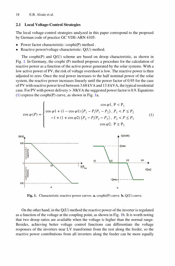
The cosphi(P) and Q(U) scheme are based on droop characteristic, as shown inFig. 1. In Germany, the cosphi (P) method proposes a procedure for the calculation ofreactive power as a function of the active power generated by the solar systems. With alow active power of PV, the risk of voltage overshoot is low. The reactive power is thenadjusted to zero. Once the real power increases to the half nominal power of the solarsystem, the reactive power increases linearly until the power factor of 0.95 for the caseof PV with reactive power level between 3.68 kVA and 13.8 kVA, the typical residentialcase. For PV with power delivery > 30kVA the suggested power factor is 0.9. Equations(1) express the cosphi(P) curve, as shown in Fig. 1a.
(1)
Fig. 1. Characteristic reactive power curves. a. cosphi(P) curve. b. Q(U) curve.
On the other hand, in the Q(U) method the reactive power of the inverter is regulatedas a function of the voltage at the coupling point, as shown in Fig. 1b. It is worth notingthat two droop ratios are available when the voltage is higher than the normal range.Besides, achieving better voltage control functions can differentiate the voltageresponses of the inverters near LV transformer from the rest along the feeder, so thereactive power contributions from all inverters along the feeder can be more equally
18 E.B. Alzate et al.
distributed as in the case of the cosphi(P) method [10]. As stated in the German GC, thedroop curve for the Q(U) method is provided by the network operator.
The algorithm for Q(U) method can be summarized by (2).
(2)
2.2 Central Voltage-Control Strategies
The technical effectiveness of local voltage-control strategies has been very wellstudied. In particular, study [2] finds that many inverters have the capability ofproviding reactive power to the grid in order to reduce the voltage rise. Using a similarmethod, study [3, 6] find that a decentralized voltage-control strategy works just aswell, via special located measurement systems, distribution OLTC transformers andcontrollable PV inverters.
In contrast, central control strategy aims for coordinated control of the complete LVdistribution system by using the static and dynamic system information. The target ofthis strategy is to find the OPF of the LV distribution systems with high penetration ofPV. OPF has been the predominant method for such analysis since its introduction byCarpentier (1962) [12].
OPF seeks to optimize a given cost, planning, or reliability objective by controllingthe power within an electrical network without violating network power constraints orsystem and equipment operating limits. Such as conventional power analysis, OPFdetermines voltage, current, and injected power throughout an electrical power system,that is, the system’s state of operation. The general OPF problem is a nonlinear, non-convex, large-scale optimization problem which may contain both continuous anddiscrete control variables [11].
The most common OPF objective function for the case of PV integration are: Powerloss minimization (PLM) [14–16], Voltage rise minimization (VRM) [17–19], PVgeneration cost minimization (GCM) [20–22], and their combination as multi-objectiveOPF problems [10, 13, 24, 25, 27].
In the case of VRM, it can be implemented with local control approaches, but theline impedances data is required for the calculation. As when it is implemented in acentral control scheme, this approach becomes a similar optimization problem as thePLM strategy [13]. So, this formulation is used as reference to compare the improve‐ments of the proposed central voltage-control strategy, as follows.
A Novel Central Voltage-Control Strategy 19
2.3 Proposed Central Voltage-Control Strategy
It is well known that central control strategies require the information of the gridtopology and the characteristics of the distribution systems, as well as the current statusof the buses in terms of voltage, reactive and active power. As the dynamic informationis usually only available for a few locations in the system, some distributed state esti‐mation algorithms are required to guarantee the power flow calculation [29, 31].However, few studies have integrated the actual ICT components of the smart LVdistribution networks into the central control strategy [13, 27]. Smart meter is one ofthese ICT components, which is possible to avoid the necessity of complex state esti‐mation algorithms.
The analysis of the information received from the smart meters allows the powerflow calculation of the smart LV distribution system, as presented by the authors in [30]for the implementation of OPF for the central voltage-control methodology. To do so,the proposed control system computes the reactive reference values for the controllablePV inverters every 10 s by minimizing a multi-objective problem using a sequentialquadratic programming algorithm developed in Matlab®.
The multi-objective function consists in three optimization objectives, as follows.Minimization of the power losses:
(3)
where i,j = 1,2,…,n is the bus number, Rij, Sij and Uij are the resistance of the branchbetween nodes, the power and voltage obtained from the power flow calculationrespectively.
Minimization of the amount of power provided by the PV systems:
(4)
where denotes the set of buses with PV installation [27].Minimization of the violations to a dead filter-based band to smooth the reactive
fluctuations:
(5)
where is the reactive power for the PV inverter in the bus number, and is the outputof a Parzen window filter designed to smooth the reactive power fluctuations.
This FIR filter is based on a buffer with the last smoothed reactive power outputs,on which the buffer size corresponds to the size of the average window.
Finally the proposed OPF formulation is as follows:
where Wo are the weighting factors for each objective function;
20 E.B. Alzate et al.
subject to:
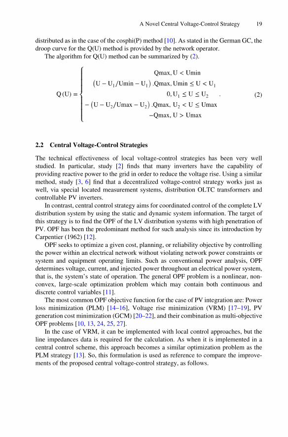
where and denote voltage boundaries and corresponds to the maximalreactive power provided by the PV inverter. A basic System schematic of a Smart LVdistribution network with the proposed central voltage-control strategy is presented inFig. 2.
Fig. 2. Smart LV distribution network with central voltage-control strategy.
2.4 Implementation of the Central Voltage-Control Strategy
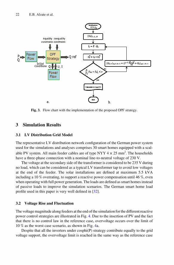
Figure 3a outlines the architecture of the central strategy developed. For each sampletime a power flow analysis is done with the flat start conditions for voltage
, the set active power generation and the reactive power for the PVinverters as Then, the OPF algorithm takes as reference the output valuesof the power flow algorithm to find a feasible solution for the defined objective functionand the respective restrictions.
Afterwards, the output values of the OPC algorithm are given as reference to theinverters and other load flow analysis is done to check the status of the system and givinga feedback to the OPF algorithms for the smoothing function.
Figure 3b shows the flow chart of the proposed formulation for power flow calcu‐lation based on the analysis of the information provided from the smart meters. Moredetailed description of the power flow calculation with the smart meter information canbe found in [30].
A Novel Central Voltage-Control Strategy 21
3 Simulation Results
3.1 LV Distribution Grid Model
The representative LV distribution network configuration of the German power systemused for the simulations and analyses comprises 30 smart homes equipped with a scal‐able PV system. All main feeder cables are of type NYY 4 × 25 mm2. The householdshave a three-phase connection with a nominal line-to-neutral voltage of 230 V.
The voltage at the secondary side of the transformer is considered to be 235 V duringno load, which can be considered as a typical LV transformer tap to avoid low voltagesat the end of the feeder. The solar installations are defined at maximum 5.5 kVAincluding a 10 % overrating, to support a reactive power compensation until 46 %, evenwhen operating with full power generation. The loads are defined as smart homes insteadof passive loads to improve the simulation scenarios. The German smart home loadprofile used in this paper is very well defined in [32].
3.2 Voltage Rise and Fluctuation
The voltage magnitude along feeders at the end of the simulation for the different reactivepower control strategies are illustrated in Fig. 4. Due to the insertion of PV and the factthat there is no control law in the reference case, overvoltage occurs over the limit of10 % as the worst case scenario, as shown in Fig. 4a.
Despite that all the inverters under cosphi(P) strategy contribute equally to the gridvoltage support, the overvoltage limit is reached in the same way as the reference case
Fig. 3. Flow chart with the implementation of the proposed OPF strategy.
22 E.B. Alzate et al.
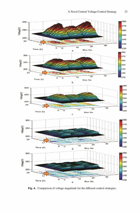
Fig. 4. Comparison of voltage magnitude for the different control strategies.
A Novel Central Voltage-Control Strategy 23
with a decrease only of 8 %, as shown in Fig. 4b. In the case of Q(U) method, theovervoltage is less in comparison with the cosphi(P) case, but some overvoltage isevident as seen in Fig. 4c.
As could be expected, the bus voltages in the optimization cases remain closer to thenominal value in both cases. It can be observed that the typical optimization strategyallows a several reduction in the voltage level around the nominal value, but the voltagemagnitude presents a higher fluctuation, as shown in Fig. 4d. In the case of the proposedstrategy, the voltage profiles are more homogeneous close to the references, as seen inFig. 4e.
3.3 Network Power Loss
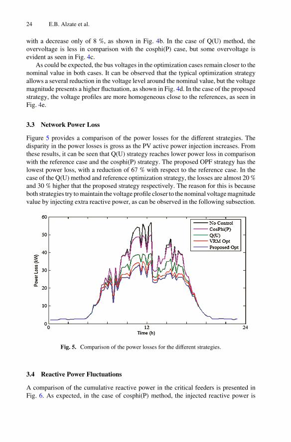
Figure 5 provides a comparison of the power losses for the different strategies. Thedisparity in the power losses is gross as the PV active power injection increases. Fromthese results, it can be seen that Q(U) strategy reaches lower power loss in comparisonwith the reference case and the cosphi(P) strategy. The proposed OPF strategy has thelowest power loss, with a reduction of 67 % with respect to the reference case. In thecase of the Q(U) method and reference optimization strategy, the losses are almost 20 %and 30 % higher that the proposed strategy respectively. The reason for this is becauseboth strategies try to maintain the voltage profile closer to the nominal voltage magnitudevalue by injecting extra reactive power, as can be observed in the following subsection.
Fig. 5. Comparison of the power losses for the different strategies.
3.4 Reactive Power Fluctuations
A comparison of the cumulative reactive power in the critical feeders is presented inFig. 6. As expected, in the case of cosphi(P) method, the injected reactive power is
24 E.B. Alzate et al.
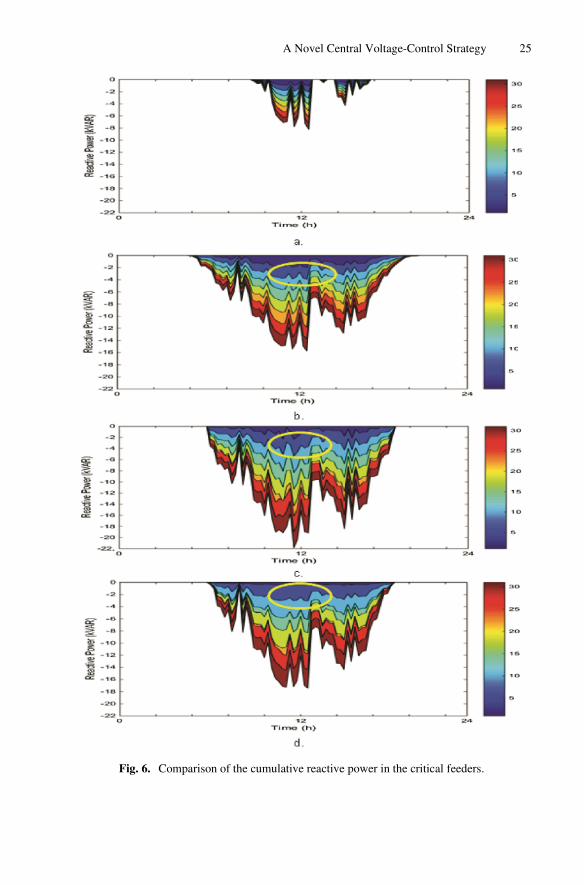
Fig. 6. Comparison of the cumulative reactive power in the critical feeders.
A Novel Central Voltage-Control Strategy 25
relative low and has the same performance for all the analyzed households, as shown inFig. 6a. In the case of Q(U) method, as the reactive power depends on the voltagemagnitude measured at its corresponding coupling point, the cumulative reactive powerincreases proportionally at the increasing of the PV active power injection, as shown inFig. 6b.
Typically, the reactive power fluctuations of PV systems for the OPF case reach orexceed the performance of the PV active power injection, due to the influence of theminimization voltage rise function, which attends to deal with the deviation of thevoltage magnitude even for negatives values. Figure 6c and d show the cumulativereactive power of the reference OPC strategy and the proposed strategy respectively.
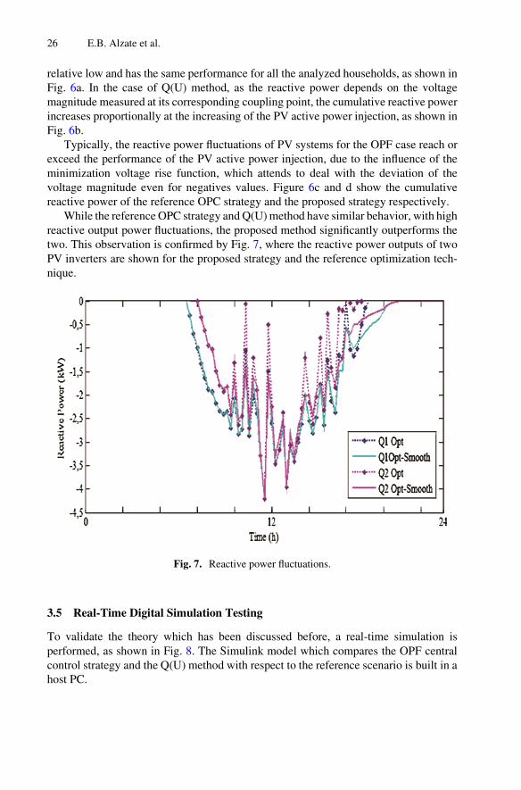
While the reference OPC strategy and Q(U) method have similar behavior, with highreactive output power fluctuations, the proposed method significantly outperforms thetwo. This observation is confirmed by Fig. 7, where the reactive power outputs of twoPV inverters are shown for the proposed strategy and the reference optimization tech‐nique.
Fig. 7. Reactive power fluctuations.
3.5 Real-Time Digital Simulation Testing
To validate the theory which has been discussed before, a real-time simulation isperformed, as shown in Fig. 8. The Simulink model which compares the OPF centralcontrol strategy and the Q(U) method with respect to the reference scenario is built in ahost PC.
26 E.B. Alzate et al.
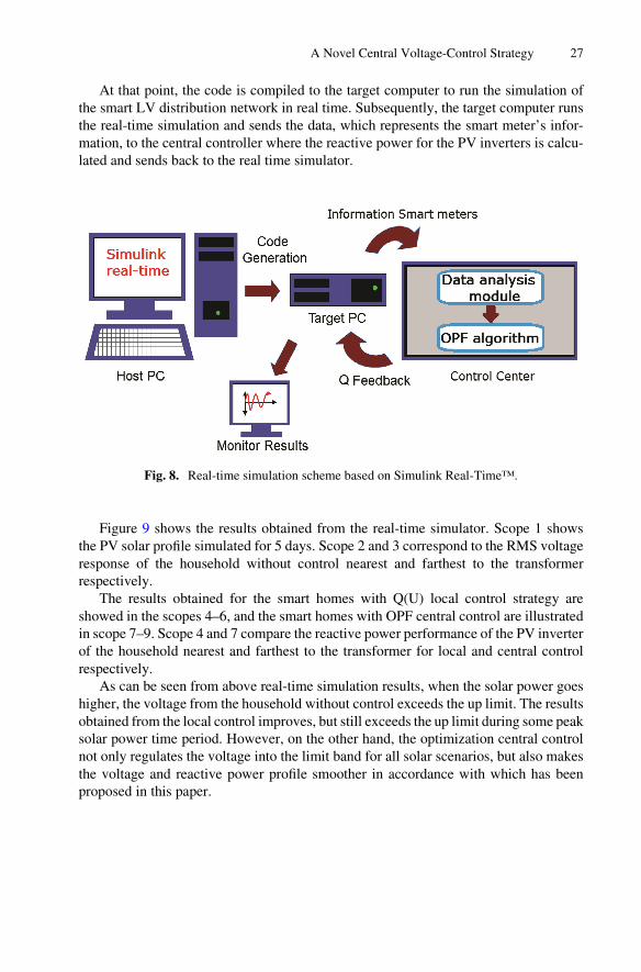
At that point, the code is compiled to the target computer to run the simulation ofthe smart LV distribution network in real time. Subsequently, the target computer runsthe real-time simulation and sends the data, which represents the smart meter’s infor‐mation, to the central controller where the reactive power for the PV inverters is calcu‐lated and sends back to the real time simulator.
Fig. 8. Real-time simulation scheme based on Simulink Real-Time™.
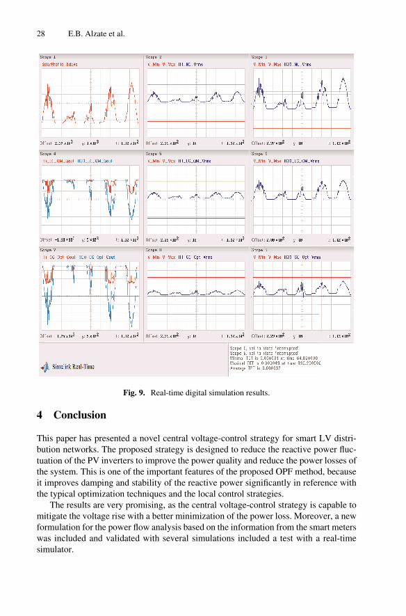
Figure 9 shows the results obtained from the real-time simulator. Scope 1 showsthe PV solar profile simulated for 5 days. Scope 2 and 3 correspond to the RMS voltageresponse of the household without control nearest and farthest to the transformerrespectively.
The results obtained for the smart homes with Q(U) local control strategy areshowed in the scopes 4–6, and the smart homes with OPF central control are illustratedin scope 7–9. Scope 4 and 7 compare the reactive power performance of the PV inverterof the household nearest and farthest to the transformer for local and central controlrespectively.
As can be seen from above real-time simulation results, when the solar power goeshigher, the voltage from the household without control exceeds the up limit. The resultsobtained from the local control improves, but still exceeds the up limit during some peaksolar power time period. However, on the other hand, the optimization central controlnot only regulates the voltage into the limit band for all solar scenarios, but also makesthe voltage and reactive power profile smoother in accordance with which has beenproposed in this paper.
A Novel Central Voltage-Control Strategy 27
4 Conclusion
This paper has presented a novel central voltage-control strategy for smart LV distri‐bution networks. The proposed strategy is designed to reduce the reactive power fluc‐tuation of the PV inverters to improve the power quality and reduce the power losses ofthe system. This is one of the important features of the proposed OPF method, becauseit improves damping and stability of the reactive power significantly in reference withthe typical optimization techniques and the local control strategies.
The results are very promising, as the central voltage-control strategy is capable tomitigate the voltage rise with a better minimization of the power loss. Moreover, a newformulation for the power flow analysis based on the information from the smart meterswas included and validated with several simulations included a test with a real-timesimulator.
Fig. 9. Real-time digital simulation results.
28 E.B. Alzate et al.
References
1. Mihet-Popa, L., Han, X., Bindner, H., Pihl-Andersen, J., Mehmedalic, J.: Development andmodeling of different scenarios for a smart distribution grid. In: IEEE 8th InternationalSymposium on Applied Computational Intelligence and Informatics (SACI), pp. 437–442(2013)
2. Dimeas, A., Drenkard, S., Hatziargyriou, N., Weidlich, A.: Smart houses in the smart grid:developing an interactive network. Electrification Mag. IEEE 2(1), 81–93 (2014)
3. Casolino, G.M., Di Fazio, A.R., Losi, A., Russo, M.: Smart modeling and tools for distributionsystem management and operation. In: 2012 IEEE International on Energy Conference andExhibition (ENERGYCON), pp. 635–640 (2012)
4. Liu, H., Jin, L., Le, D., Chowdhury, A.A.: Impact of high penetration of solar photovoltaicgeneration on power system small signal stability. In: 2010 International Conference onPower System Technology (POWERCON), pp. 24–28 (2010)
5. Mihet-Popa, L., Han, X., Bindner, H., Pihl-Andersen, J., Mehmedalic, J.: Grid modeling,analysis and simulation of different scenarios for a smart low-voltage distribution grid. In:2013 4th IEEE/PES on Innovative Smart Grid Technologies Europe (ISGT EUROPE), pp.6–9 (2013)
6. Tonkoski, R., Lopes, L.A.C.: Coordinated active power curtailment of grid connected PVinverters. IEEE Trans. Sustain. Energy 2(2), 139–147 (2011)
7. Nyborg, S., Røpke, I.: BEnergy impacts of the smart home – conflicting visions. In:Conference Proceedings, Energy Efficiency First: The Foundation of a Low-Carbon Society(ECEEE), pp. 1849–1860 (2011)
8. Austrian Institute of Technology (AT): DG Demonet Smart LV Grid, AT (2011)9. Katiraei, F., Agüero, J.R.: Solar PV integration challenges. Power Energy Mag. IEEE 9(3),
62–71 (2011)10. Juanperez, M., Yang, G., Kjær, S.: Voltage regulation in LV grids by coordinated volt-var
control strategies. J. Mod. Power Syst. Clean Energy 2, 319–328 (2014)11. Frank, S., Steponavice, I., Rebennack, S.: Optimal power flow: a bibliographic survey I.
Energy Syst. 3, 221–258 (2012)12. Carpentier, J.: Contribution to the economic dispatch problem. Bull. Soc. Fr. Electr. 8, 431–
447 (1962)13. Kabiri, R., Holmes, D.G., McGrath, B.P.: The influence of PV inverter reactive power
injection on grid voltage regulation. In: 2014 IEEE 5th International Symposium on PowerElectronics for Distributed Generation Systems (PEDG), pp. 24–27 (2014)
14. Ravindran, V., Aravinthan, V.: Feeder level power loss reduction through reactive powercontrol with presence of distributed generation, pp. 1–25 (2013)
15. Golshan, M.E.H., Arefifar, S.A.: Distributed generation, reactive sources and network-configuration planning for power and energy-loss reduction. IEEE Proc. Gener. Transm.Distrib. 153(2), 127–136 (2006)
16. Yeh, H.-G., Gayme, D.F., Low, S.H.: Adaptive VAR control for distribution circuits Withphotovoltaic generators. IEEE Trans. Power Syst. 27(3), 1656–1663 (2012)
17. Carvalho, P.M.S., Correia, P.F., Ferreira, L.A.F.: Distributed reactive power generationcontrol for voltage rise mitigation in distribution networks. IEEE Trans. Power Syst. 23(2),766–772 (2008)
18. Yeh, H.-G., Gayme, D.F., Low, S.H.: Adaptive VAR control for distribution circuits withphotovoltaic generators. IEEE Trans. Power Syst. 27(3), 1656–1663 (2012)
A Novel Central Voltage-Control Strategy 29
19. Cagnano, A., De Tuglie, E., Dicorato, M., Forte, G., Trovato, M.: PV plants for voltageregulation in distribution networks, In: 2012 47th International on Universities PowerEngineering Conference (UPEC), pp. 4–7 (2012)
20. Chakraborty, S., Simoes, M.G.: PV-microgrid operational cost minimization by neuralforecasting and heuristic optimization. In: Industry Applications Society Annual Meeting,pp. 5–9. IEEE (2008)
21. Budischak, C., Sewell, D., Thomson, H.: Cost-minimized combinations of solar power andelectrochemical storage, powering the grid up to 99.9 % of the time. J. Power Sources 232,15 (2013)
22. Mills, A.D., Wiser, R.H.: Strategies to mitigate declines in the economic value of wind andsolar at high penetration in California. Appl. Energy 147, 269–278 (2015)
23. Golestani, S., Tadayon, M.: Distributed generation dispatch optimization by artificial neuralnetwork trained by particle swarm optimization algorithm. In: 2011 8th InternationalConference on the European Energy Market (EEM), pp. 543–548 (2011)
24. Sulc, P., Backhaus, S., Chertkov, M.: Optimal distributed control of reactive power via thealternating direction method of multipliers. IEEE Trans. Energy Convers. 29(4), 968–977(2014)
25. Kundu, S., Backhaus, S., Hiskens, I.A.: Distributed control of reactive power fromphotovoltaic inverters. In: 2013 IEEE International Symposium on Circuits and Systems(ISCAS), pp. 249–252 (2013)
26. Boyd, S., Parikh, N., Chu, E.: Distributed optimization and statistical learning via thealternating direction method of multipliers. Found. Trends Mach. Learn. 3(1), 1–122 (2011)
27. Su, X., Masoum, M.A.S., Wolfs, P.J.: Optimal PV inverter reactive power control and realpower curtailment to improve performance of unbalanced four-wire LV distributionnetworks. IEEE Trans. Sustain. Energy 5(3), 967–977 (2014)
28. Liu, X., Aichhorn, A., Liu, L., Hui, L.: Coordinated control of distributed energy storagesystem with tap changer transformers for voltage rise mitigation under high photovoltaicpenetration. IEEE Trans. Smart Grid 3(2), 897–906 (2012)
29. von Appen, J., Braun, M., Stetz, T., Diwold, K., Geibel, D.: Time in the sun: the challengeof high PV penetration in the german electric grid. IEEE Power Energy Mag. 11(2), 55–64(2013)
30. Alzate, E.B., Mallick, N.H., Xie, J.: A high-resolution smart home power demand model andfuture impact on load profile in Germany. In: 2014 IEEE International Conference on Powerand Energy (PECON), pp. 53–58 (2014)
31. Diwold, K., Yan, W., De Alvaro Garcia, L., Mocnik, L.,Braun, M.: Coordinated voltage-control in distribution systems under uncertainty. In: 2012 47th International on UniversitiesPower Engineering Conference (UPEC), pp. 4–7 (2012)
32. Department of Energy Technology- Aalborg University, Development of a Secure, Economicand Environmentally friendly Modern Power System. DK (2010)
33. Neusel-Lange, N., Oerter, C.: Intelligente Lösungen für Verteilnetze, VDE-Insidel (2012)34. RWE, Technical University of Dortmund, ABB, and Consentec: Smart Country,
Herausforderungen und intelligente Lösungen für die Energiewende auf dem Land., Germany(2011)
35. Turitsyn, K., Sulc, P., Backhaus, S., Chertkov, M.: Options for control of reactive power bydistributed photovoltaic generators. Proc. IEEE 99(6), 1063–1073 (2011)
36. Technische Universität München, Georg-Simon-Ohm Hochschule Nürnberg, Siemens AG,and Power Plus Communications AG, Projekt Netz, Germany (2009)
30 E.B. Alzate et al.

http://www.springer.com/978-3-319-27429-4