Embed Size (px)
Citation preview
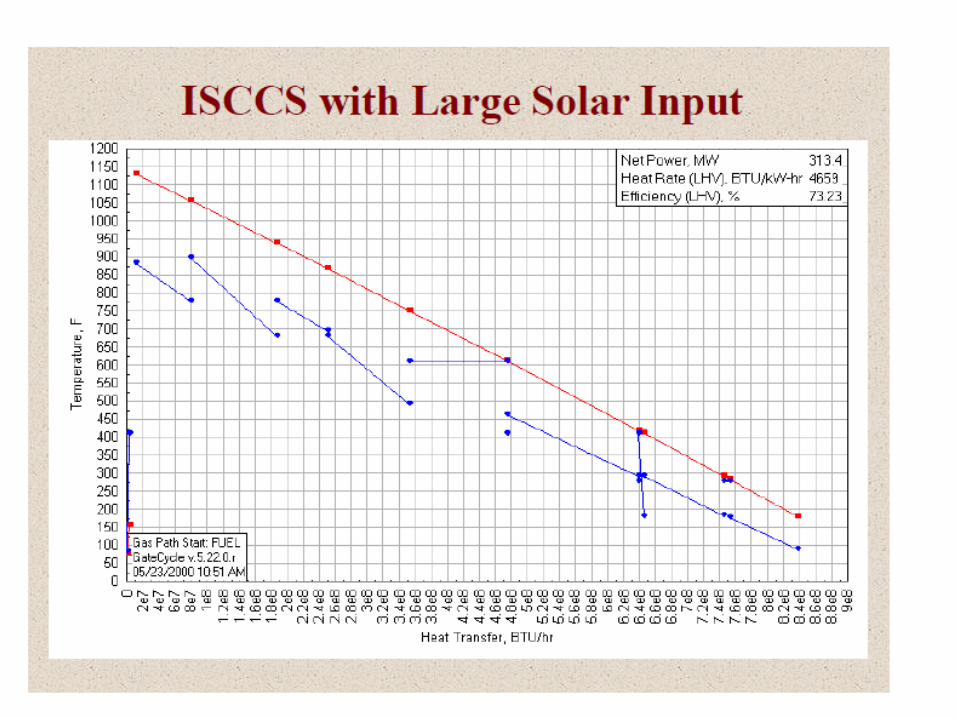
A novel IGCC system with steam injected H2/O2cycle and CO2 recovery
P M V Subbarao
Professor
Mechanical Engineering Department
Low Quality Fuel but High Efficiency Unit….
The Curtain Raiser
• The integrated gasification combined cycle (IGCC) is one of the advanced clean coal power generation systems.
• Compared with the conventional coal fired power plant, it has lower emissions of SO2, NOX and particle pollutants.
• Though it is reputed to be the cleanest coal fired power plant, CO2 emission cannot be greatly reduced by this technology.
• Only proportionally reduced with improvement of the IGCC system efficiency.
• How to reduce CO2 emission effectively from the IGCC system becomes the main subject of researchers.
CO2 Recovery
• Generally, there are five ways to separate and recover CO2 from the IGCC system.
• (1) CO2 separation and recovery from the exhaust fuel gas;
• (2) CO2 sequestration before combustion;
• (3) CO2 sequestration by a polygeneration system that combines the IGCC system with chemical processes;
• (4) CO2 recovery using integrated thermal cycles with fuel oriented transfer; and
• (5) CO2 separation and recovery based on a novel thermal cycle, the semi-closed O2/CO2 cycle IGCC.

• IGCC combustion products mainly consist of CO2 and H2O, and hence, it separates CO2 without extra energy consumption.
• However, the O2 production and CO2 recovery demand large energy consumptions.
• The energy penalty for separating and recovering CO2 will bring an efficiency decrease of about 7 percentage points. The IGCC system with dual cycles (DC-IGCC) and less CO2 emission is another example.
• Its efficiency decrease is less than 4 percentage points after separating and recovering CO2.
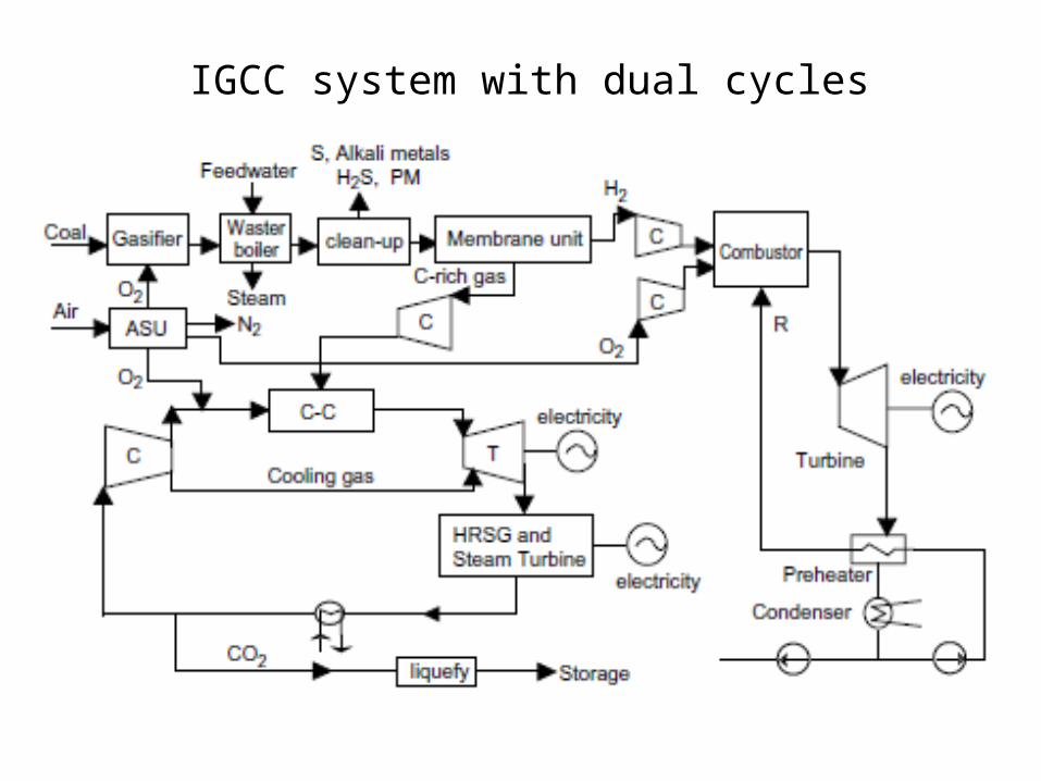
IGCC system with dual cycles
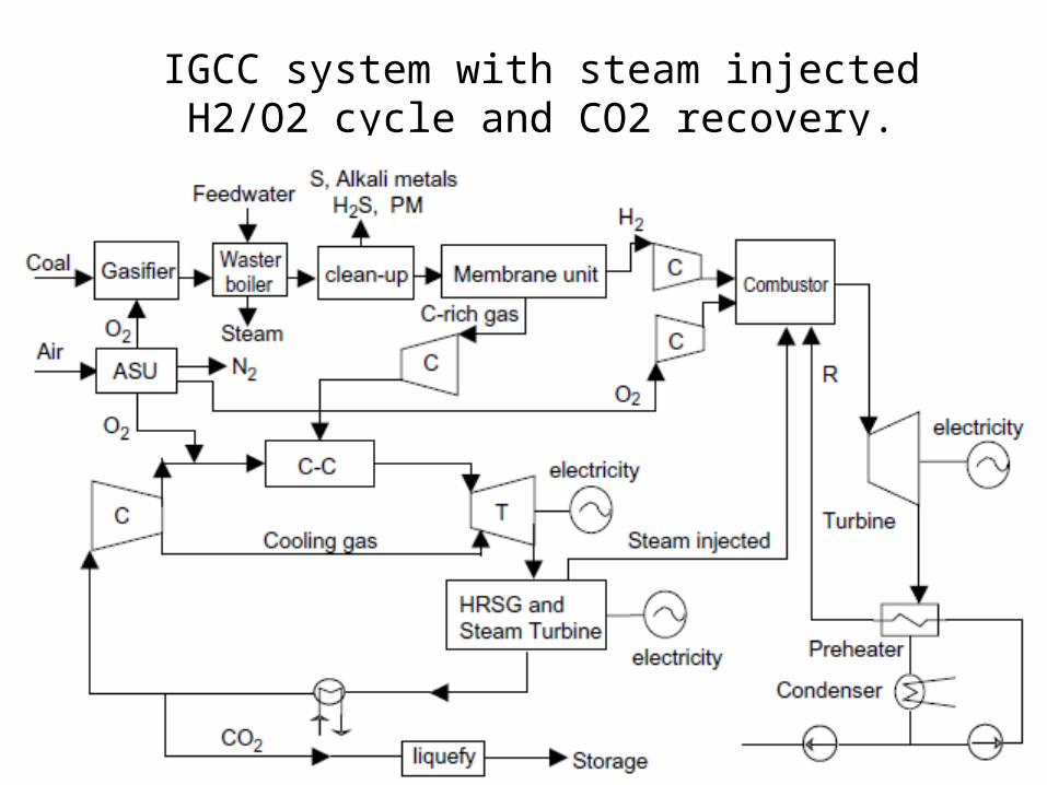
IGCC system with steam injected H2/O2 cycle and CO2 recovery.
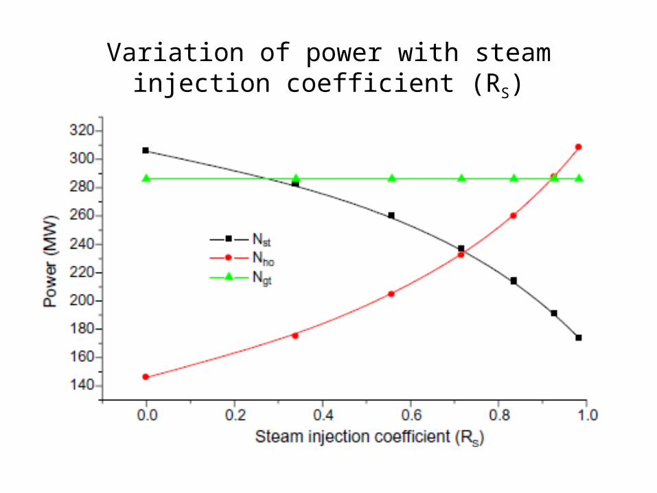
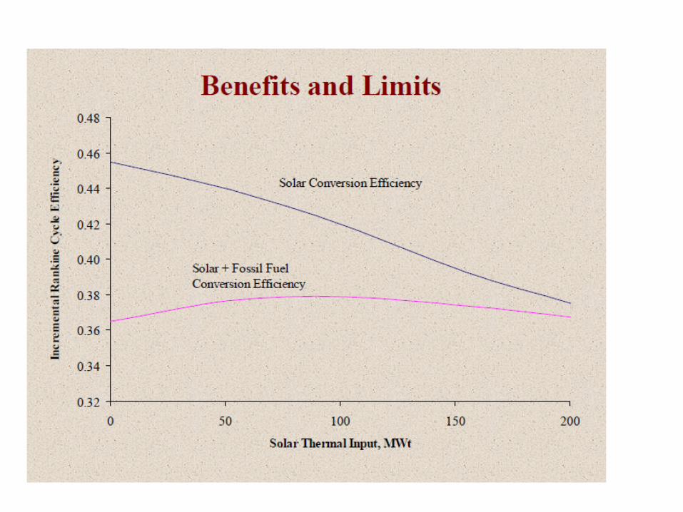
Variation of power with steam injection coefficient (RS)
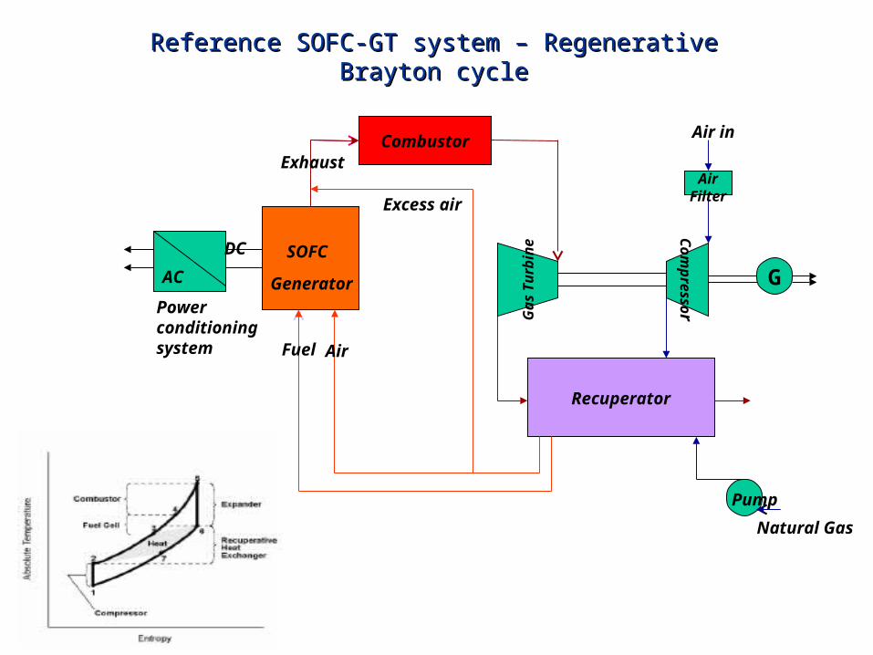
Reference SOFC-GT system – Regenerative Brayton cycleReference SOFC-GT system – Regenerative Brayton cycle
SOFC
Generator
DC
AC
Power conditioning system
Combustor
Recuperator
AirFilter
Pump
G
Natural Gas
Air in
Com
pressor
AirFuel
Exhaust
Gas
Tu
rbin
e
Excess air

0
0.2
0.4
0.6
0.8
1
1.2
1.4
0 1 2 3 4 5
stack capacity (MW)
Ne
t h
ea
t g
en
era
tio
n (
MW
)
Net heat produced in the fuel cell stack Vs Stack capacityNet heat produced in the fuel cell stack Vs Stack capacity
Methane and air as a fuel.
Operates at 4 bar, 1073 K
Fuel utilization factor of 80%
Heat generated from the stack is approximately 25% of the stack capacity.
Heat generation is almost linear
Stack effluent consist of 20% of unutilized fuel and products
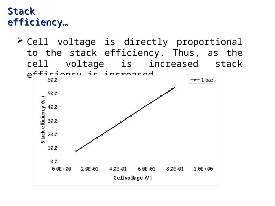
Stack efficiency…Stack efficiency…
Cell voltage is directly proportional to the stack efficiency. Thus, as the cell voltage is increased stack efficiency is increased.
0.0
10.0
20.0
30.0
40.0
50.0
60.0
0.0E+00 2.0E-01 4.0E-01 6.0E-01 8.0E-01 1.0E+00
Cell voltage (V)
Sta
ck e
ffic
ien
cy (
%)
1 bar

Bottoming cycle power output Bottoming cycle power output
After reaching the optimum pressure, turbine power output decreases asserting that this is the optimized value.
This is because of the decrement in TIT due to the shift of heat recovery.
0
0.05
0.1
0.15
0.2
0.25
0 2 4 6 8Inlet pressure (bar)
Bo
tto
min
g c
ycle
po
wer
ou
tpu
t (M
W)
UF = 0.7
UF = 0.75
UF = 0.8
UF = 0.85
From 1 MW SOFC stack
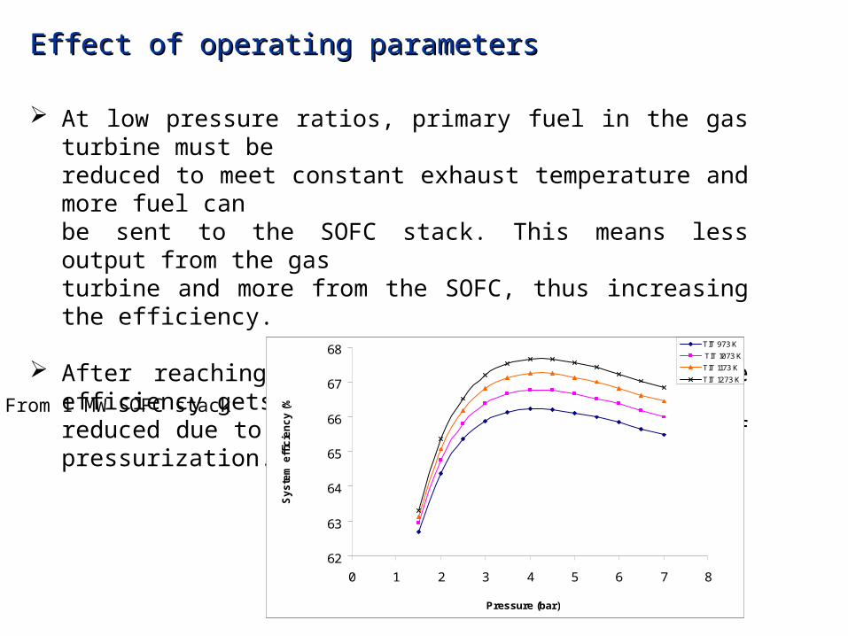
Effect of operating parametersEffect of operating parameters
At low pressure ratios, primary fuel in the gas turbine must bereduced to meet constant exhaust temperature and more fuel canbe sent to the SOFC stack. This means less output from the gasturbine and more from the SOFC, thus increasing the efficiency.
After reaching optimum pressure, overall cycle efficiency getsreduced due to high power consumption because of pressurization.
62
63
64
65
66
67
68
0 1 2 3 4 5 6 7 8
Pressure (bar)
Sy
ste
m e
ffic
ien
cy
(%
)
TIT 973 K
TIT 1073 K
TIT 1173 K
TIT 1273 K
From 1 MW SOFC stack
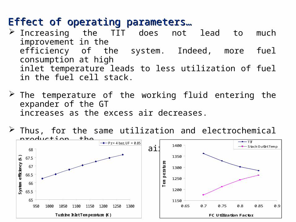
Effect of operating parameters…Effect of operating parameters… Increasing the TIT does not lead to much improvement in the
efficiency of the system. Indeed, more fuel consumption at highinlet temperature leads to less utilization of fuel in the fuel cell stack.
The temperature of the working fluid entering the expander of the GTincreases as the excess air decreases.
Thus, for the same utilization and electrochemical production, therequirement to heat less air results in higher TIT and higher overallefficiency.
65
65.5
66
66.5
67
67.5
68
950 1000 1050 1100 1150 1200 1250 1300
Turbine Inlet Temperature (K)
Sys
tem
eff
icie
ncy
(%
)
Pr = 4 bar, UF = 0.85
1150
1200
1250
1300
1350
1400
0.65 0.7 0.75 0.8 0.85 0.9
FC Utilization Factor
Tem
pera
ture
(K
)
TIT
Stack Outlet Temp
FindingsFindings
From the above it is clear that electrical efficiency of the system
can be as high as 65%.
Increase in operating pressure increases the overall system
efficiency. But, high pressures lead to cost, so, there should be
a balance between the development cost and the efficiency.
Decreasing the excess air in the SOFC-GT has a positive effect
on the overall efficiency.
Also, simulation results show that the cell voltage is about 0.7V
with electrical efficiency of the plant better than 65%.
FindingsFindings……
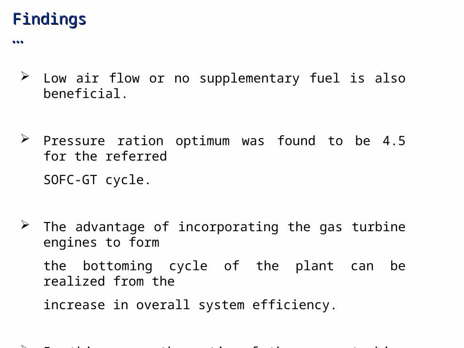
Low air flow or no supplementary fuel is also beneficial.
Pressure ration optimum was found to be 4.5 for the referred
SOFC-GT cycle.
The advantage of incorporating the gas turbine engines to form
the bottoming cycle of the plant can be realized from the
increase in overall system efficiency.
In this case, the ratio of the power turbine AC output to the
SOFC stack AC output is about 25%.

THANK YOU