Embed Size (px)
Citation preview
A Novel Low-Temperature Diffusion Aluminide Coating for Ultrasupercritical Coal-Fired Boiler Applications
A Final Scientific/Technical Report
for
DOE Award No. DE-FG26-06NT42674
Jan. 1, 2006 – Dec. 31, 2009
Submitted by
Ying Zhang, Principal Investigator
Department of Mechanical Engineering 115 W. 10th Street, TTU Box 5014
Tennessee Technological University, Cookeville, TN 38505
Report Issued in March, 2010
DISCLAIMER: This report was prepared as an account of work sponsored by an agency of the United States Government. Neither the United States Government nor any agency thereof, nor any of their employees, makes any warranty, expressed or implied, or assumes any legal liability or responsibility for the accuracy, completeness, or usefulness of any information, apparatus, product, or process disclosed, or represents that its use would not infringe privately owned rights. Reference herein to any specific commercial product, process, or service by trade name, trademark, manufacturer, or otherwise, does not necessarily constitute or imply its endorsement, recommendation, or favoring by the United States Government or any agency thereof. The views and opinions of authors expressed herein do not necessarily state or reflect those of the United States Government or any agency thereof.
TABLE OF CONTENTS
EXECUTIVE SUMMARY.......................................................................................... 1
1. INTRODUCTION ................................................................................................. 3
2. EXPERIMENTAL PROCEDURE .........................................................................4
2.1. The Materials and Specimen Preparation ............................................................4
2.2. The Coating Process ...........................................................................................5
2.3. Oxidation Experiments in Humid Air..................................................................8
2.4. Creep Experiments..............................................................................................9
2.5. Characterization of Coating Specimens.............................................................11
3. RESULTS AND DISCUSSION ............................................................................11
3.1. Thermodynamic Considerations .......................................................................11
3.2. As-Deposited Coatings......................................................................................12
3.3. Oxidation Performance of Low-Temperature Coatings......................................22
3.4. Effect of Low-Temperature Coatings on Creep Resistance of Coated Alloys.....31
4. CONCLUSIONS ...................................................................................................35
5. ACKNOWLEDGEMENTS ..................................................................................36
6. REFERENCES .....................................................................................................37
1
EXECUTIVE SUMMARY
An ultrasupercritical (USC) boiler with higher steam temperature and pressure is expected to increase the efficiency of the coal-fired power plant and also decrease emissions of air pollutants. Ferritic/martensitic alloys have been developed with good creep strength for the key components in coal-fired USC plants. However, they typically suffer excessive steam-side oxidation, which contributes to one of main degradation mechanisms along with the fire-side corrosion in coal-fired boilers. As the steam temperature further increases in USC boilers, oxidation of the tube internals becomes an increasing concern, and protective coatings such as aluminide-based diffusion coatings need to be considered. However, conventional aluminizing processes via pack cementation or chemical vapor deposition are typically carried out at elevated temperatures (1000-1150 °C). Thermochemical treatment of ferritic/martensitic alloys at such high temperatures could severely degrade their mechanical properties, particularly the alloy’s creep resistance. The research focus of this project was to develop an aluminide coating with good oxidation resistance at temperatures 700 °C so that the coating processing would not detrimentally alter the creep performance of the ferritic/martensitic alloys.
Nevertheless, when the aluminizing temperature is lowered, brittle Al-rich
intermetallic phases, such as Fe2Al5 and FeAl3, tend to form in the coating, which may reduce the resistance to fatigue cracking. Al-containing binary masteralloys were selected based on thermodynamic calculations to reduce the Al activity in the pack cementation process and thus to prevent the formation of brittle Al-rich intermetallic phases. Thermodynamic computations were carried out using commercial software HSC 5.0 for a series of packs containing various Cr-Al binary masteralloys. The calculation results indicate that the equilibrium partial pressures of Al halides at 700 °C were a function of Al content in the Cr-Al alloys. Cr-25Al and Cr-15Al were chosen as the masteralloys in the pack cementation process.
In contrast to pure Al masteralloy which led to the formation of Fe2Al5 coatings at
650 °C, a coating consisting of a thin Fe2Al5 outer layer and an FeAl inner layer was formed at 700 ºC with the Cr-25Al masteralloy. By switching to the Cr-15Al masteralloy, thin FeAl coatings (~12 m) containing < 50 at.% Al were achieved at 700 ºC. The effect of the amount of masteralloys on coating growth was also studied by employing packs containing 2NH4Cl-x(Cr-15Al)-(98-x)Al2O3, where x = 10, 20, 30, 40, 50, 60, and 70 wt.%. It was noticed that when the Cr-15Al masteralloy was increased from 10 to 40 wt.% in the pack, both coating thickness and surface Al content increased, suggesting that gas phase kinetics played an important role in Al deposition. However, with further increase of the masteralloy, solid state diffusion became the rate-limiting factor.
The long-term oxidation performance of the aluminide coatings synthesized at
700 °C with Cr-25Al and Cr-15Al masteralloys was evaluated in the water vapor environment at 650-700 °C. The low-temperature pack coatings demonstrated excellent oxidation resistance at 650 °C in humid air after ~1.2 yr testing. Longer lifetimes can be
2
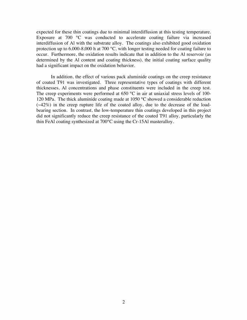
expected for these thin coatings due to minimal interdiffusion at this testing temperature. Exposure at 700 °C was conducted to accelerate coating failure via increased interdiffusion of Al with the substrate alloy. The coatings also exhibited good oxidation protection up to 6,000-8,000 h at 700 °C, with longer testing needed for coating failure to occur. Furthermore, the oxidation results indicate that in addition to the Al reservoir (as determined by the Al content and coating thickness), the initial coating surface quality had a significant impact on the oxidation behavior.
In addition, the effect of various pack aluminide coatings on the creep resistance
of coated T91 was investigated. Three representative types of coatings with different thicknesses, Al concentrations and phase constituents were included in the creep test. The creep experiments were performed at 650 °C in air at uniaxial stress levels of 100-120 MPa. The thick aluminide coating made at 1050 °C showed a considerable reduction (~42%) in the creep rupture life of the coated alloy, due to the decrease of the load-bearing section. In contrast, the low-temperature thin coatings developed in this project did not significantly reduce the creep resistance of the coated T91 alloy, particularly the thin FeAl coating synthesized at 700°C using the Cr-15Al masteralloy.
3
1. INTRODUCTION An ultrasupercritical (USC) boiler with higher steam temperature and pressure
than current boilers is expected to increase the thermal efficiency of the coal-fired power plant and also decrease emissions of air pollutants. Ferritic/martensitic steels have been developed with high creep strength for the key components in coal-fired USC plants.[1,2] However, they typically suffer excessive steam-side oxidation, which contributes to one of the main degradation mechanisms along with fire-side corrosion in coal-fired boilers. As steam temperatures further increase in USC boilers, oxidation of the tube internals will become an increasing concern.
One approach to overcoming oxidation limitations is through the use of coatings,
which are on the internal surfaces of these tubes. As compared to overlay coatings produced by thermal spray or other techniques, diffusion coating technology offers two major advantages: (i) It constitutes the only viable way to add extra alloy protection to the inside surface of steam containing tubing surface without reverting to bimetallic tubing options; (ii) It is particularly attractive because the coating is incorporated into the metal substrate, thereby avoiding spalling or other loss of the coating protection. With a compositional and microstructural gradient, the diffusion coatings can significantly reduce the mismatch in coefficient of thermal expansion between coating and substrate. In the past, iron aluminide-based diffusion coatings have been successfully applied to Fe-based alloys via pack cementation, chemical vapor deposition (CVD), and slurry techniques.
Nevertheless, nearly all previous aluminizing processes were carried out at
elevated temperatures (e.g., 1000-1150 °C) for 4-16 h.[3] Thermochemical treatment of ferritic/martensitic steels at these temperatures can severely degrade their mechanical properties such as high temperature strength and creep resistance.[4] However, as the aluminizing temperature is lowered, the tendency to forming Al-rich intermetallic phases such as FeAl3 and Fe2Al5 increases,[5,6] which could negatively affect the mechanical behavior of the coated alloy, particularly the resistance to fatigue cracking. Therefore, the main objective of this research was to develop a low-temperature ( 700 °C) diffusion aluminide coating with reduced brittleness via pack cementation for protection of USC boiler internal tubing. Al-containing binary masteralloys were identified using thermodynamic computations and physical metallurgy principles. These masteralloys were utilized to replace pure Al in order to reduce the Al activity in the aluminizing process, and thus prevent the formation of Al-rich brittle intermetallics in the coating. Another focus was to compare the low-temperature aluminide coatings with model CVD coatings [7,8] in terms of their oxidation resistance to water-vapor attack and coating microstructural evolution during thermal exposure. In addition, a very important component of this work was to investigate the effect of the low-temperature aluminide coatings on mechanical properties of substrate ferritic/martensitic alloys, in particular, their creep behavior, where very little knowledge existed.

4
2. EXPERIMENTAL PROCEDURE
2.1. The Materials and Specimen Preparation The substrate material was the commercial ferritic/martensitic alloy Fe-9Cr-1Mo
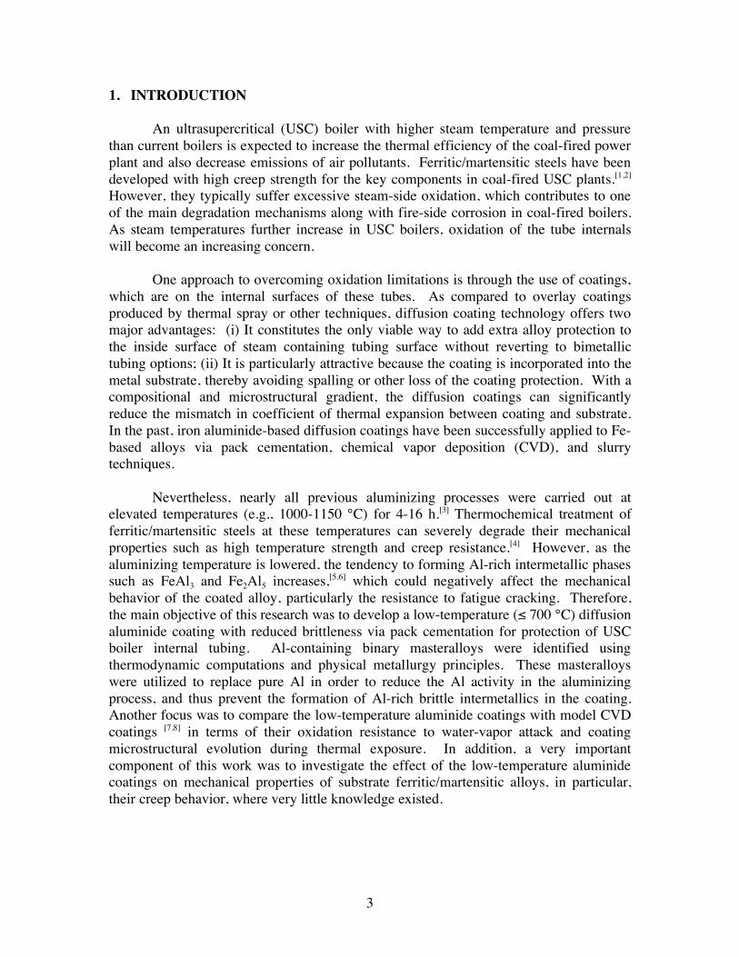
(T91); its chemical composition is given in Table 1. [10] Rectangular coupon specimens of 12 x 10 x 1.8 mm were used for coating development and for evaluation of oxidation resistance. Small dog-bone tensile samples, cut via electric-discharge machining (EDM), were used for the creep study. As shown in Fig. 1, the creep specimen exhibited the following dimensions: 25 mm total length, 2 mm thickness, 7.6 mm gauge length, together with a 7.6 mm head width and 4 mm neck radius. The gauge section of the specimen was 2 x 2 mm2, and no pinholes were machined in the head portion of the specimen.
Table 1. Chemical compositions of the substrate alloy T91.
Element wt.% at.%
Fe 88.46 87.75
Cr 9.26 9.87
Ni 0.16 0.15
Mo 0.96 0.55
Co 0.02 0.02
Cu 0.07 0.06
Mn 0.47 0.47
Si 0.19 0.37
V 0.23 0.25
Nb 0.05 0.03
P 0.013 0.0233
B 0.001 0.0051
C 516 ppm 0.2380
N 480 ppm 0.1899
O 26 ppm 0.0090
S 8 ppm 0.0014
5
All specimens were ground to a 600-grit finish and ultrasonically cleaned in hot water and acetone prior to the pack cementation process.
Fig. 1. Schematic of the test specimen dimensions (given in inches).
2.2. The Coating Process
The aluminide coatings were fabricated in a laboratory pack cementation system (Fig. 2), which consisted of a furnace, the temperature measuring/logging system, the argon supply system, a vacuum pump, and the exhaust system. The furnace was a three-zone Lindberg/Blue with a horizontal alumina tube as the coating chamber. The alumina tube had an ID of ~70 mm and a uniform heat zone of ~250 mm in the center of the furnace. A K-type thermocouple placed in the center of the heat zone was connected to a National Instruments, Ni-9211A data logger. The temperature profile was recorded by LabVIEW SignalExpress. To aid in the removal of air and moisture in the furnace chamber, a Leybold vacuum pump was connected to the furnace along with a MKS 945 pirani manometer, which was used to measure the pressure inside the coating chamber. Ultra high purity Ar (99.999%) was used in conjunction with the vacuum pump to purge the alumina chamber prior to pack cementation. The exhaust gas from the coating process was flowed through a NaOH solution to be neutralized before venting to atmosphere.

6
Fig. 2. Schematic of the pack cementation system.
The pack mixture consisted of 10-20 wt.% masteralloy (99.5%, <100 mesh;
Cerac, Inc.), 1-2 wt.% NH4Cl activator (99.999%, <10 mesh), and the balance inert Al2O3 filler (99.5%, 100-200 mesh). The pack powder was weighed and thoroughly mixed by tumbling in a jar mill for ~10-12 h.
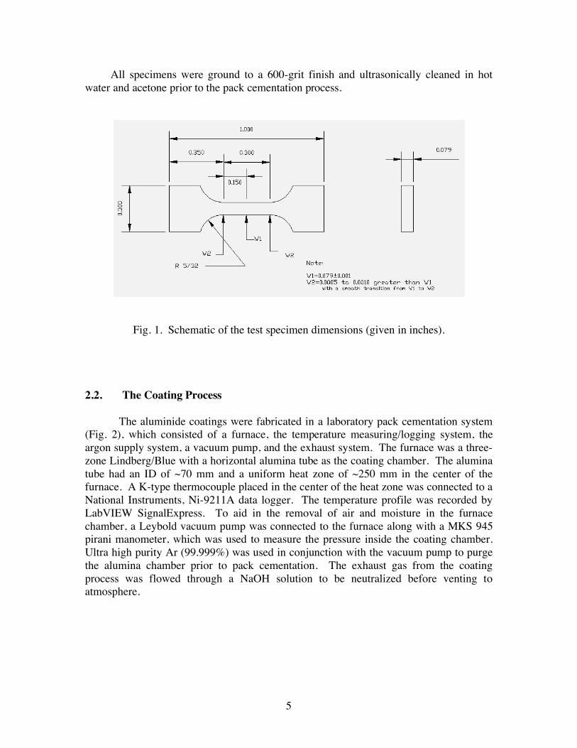
The specimens and powder mixture were loaded into an alumina crucible using
the arrangements shown in Fig. 3. The specimen was directly embedded in the powder mixture in the contact arrangement, Fig. 3a. For the non-contact arrangement [9] (Fig. 3b), the specimen was separated from the pack powder by either porous alumina paper (Zircar Ceramics, APA-2, 95% Al2O3 + 5% SiO2, with open porosity of 95%, ~1.3 mm thick) or foam disks (Zircar Ceramics, AL-30AA, 97% Al2O3 + 3% SiO2, with open porosity of 85%, ~1.2 mm thick). The crucible was sealed using an alumina-based cement (Cerambond, AREMCO Products, Inc.). The cement was dried for 2 h at room temperature and for another 10 h at 100-110 °C.
7
(a) (b)
Fig. 3. Pack-specimen arrangements for aluminizing process, (a) contact pack arrangement, and (b) non-contact pack arrangement.
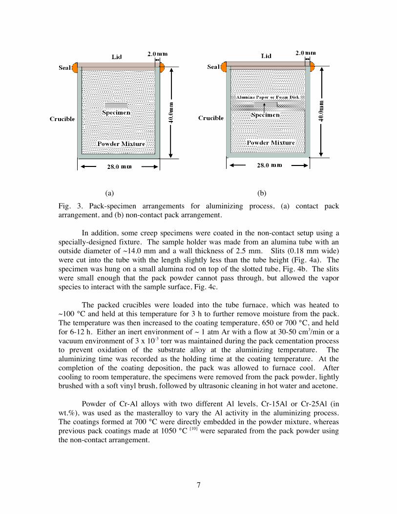
In addition, some creep specimens were coated in the non-contact setup using a
specially-designed fixture. The sample holder was made from an alumina tube with an outside diameter of ~14.0 mm and a wall thickness of 2.5 mm. Slits (0.18 mm wide) were cut into the tube with the length slightly less than the tube height (Fig. 4a). The specimen was hung on a small alumina rod on top of the slotted tube, Fig. 4b. The slits were small enough that the pack powder cannot pass through, but allowed the vapor species to interact with the sample surface, Fig. 4c.
The packed crucibles were loaded into the tube furnace, which was heated to
~100 °C and held at this temperature for 3 h to further remove moisture from the pack. The temperature was then increased to the coating temperature, 650 or 700 °C, and held for 6-12 h. Either an inert environment of ~ 1 atm Ar with a flow at 30-50 cm3/min or a vacuum environment of 3 x 10⁻³ torr was maintained during the pack cementation process to prevent oxidation of the substrate alloy at the aluminizing temperature. The aluminizing time was recorded as the holding time at the coating temperature. At the completion of the coating deposition, the pack was allowed to furnace cool. After cooling to room temperature, the specimens were removed from the pack powder, lightly brushed with a soft vinyl brush, followed by ultrasonic cleaning in hot water and acetone.
Powder of Cr-Al alloys with two different Al levels, Cr-15Al or Cr-25Al (in
wt.%), was used as the masteralloy to vary the Al activity in the aluminizing process. The coatings formed at 700 °C were directly embedded in the powder mixture, whereas previous pack coatings made at 1050 °C [10] were separated from the pack powder using the non-contact arrangement.
8
(a) (b)
(c)
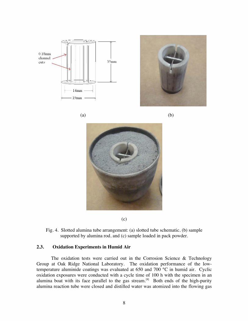
Fig. 4. Slotted alumina tube arrangement: (a) slotted tube schematic, (b) sample supported by alumina rod, and (c) sample loaded in pack powder.
2.3. Oxidation Experiments in Humid Air
The oxidation tests were carried out in the Corrosion Science & Technology Group at Oak Ridge National Laboratory. The oxidation performance of the low-temperature aluminide coatings was evaluated at 650 and 700 °C in humid air. Cyclic oxidation exposures were conducted with a cycle time of 100 h with the specimen in an alumina boat with its face parallel to the gas stream.[8] Both ends of the high-purity alumina reaction tube were closed and distilled water was atomized into the flowing gas
9
stream (850 ml/min) through an alumina tube (e.g. gas velocity of 1.7 cm/s at 700 °C) and was calibrated to 10±1 vol.% based on the amount of water injected. The specimens were cooled to room temperature and weighed after each cycle on a Mettler-Toledo model AG245 balance.
2.4. Creep Experiments
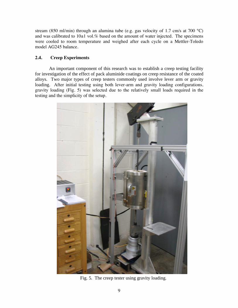
An important component of this research was to establish a creep testing facility
for investigation of the effect of pack aluminide coatings on creep resistance of the coated
alloys. Two major types of creep testers commonly used involve lever arm or gravity
loading. After initial testing using both lever-arm and gravity loading configurations, gravity loading (Fig. 5) was selected due to the relatively small loads required in the testing and the simplicity of the setup.
Fig. 5. The creep tester using gravity loading.
10
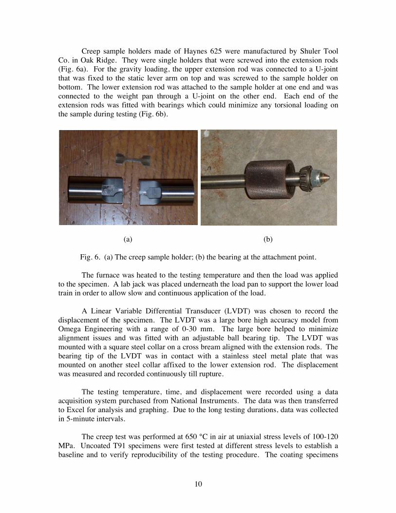
Creep sample holders made of Haynes 625 were manufactured by Shuler Tool Co. in Oak Ridge. They were single holders that were screwed into the extension rods (Fig. 6a). For the gravity loading, the upper extension rod was connected to a U-joint that was fixed to the static lever arm on top and was screwed to the sample holder on bottom. The lower extension rod was attached to the sample holder at one end and was connected to the weight pan through a U-joint on the other end. Each end of the extension rods was fitted with bearings which could minimize any torsional loading on the sample during testing (Fig. 6b).
(a) (b)
Fig. 6. (a) The creep sample holder; (b) the bearing at the attachment point. The furnace was heated to the testing temperature and then the load was applied
to the specimen. A lab jack was placed underneath the load pan to support the lower load train in order to allow slow and continuous application of the load.
A Linear Variable Differential Transducer (LVDT) was chosen to record the
displacement of the specimen. The LVDT was a large bore high accuracy model from Omega Engineering with a range of 0-30 mm. The large bore helped to minimize alignment issues and was fitted with an adjustable ball bearing tip. The LVDT was mounted with a square steel collar on a cross bream aligned with the extension rods. The bearing tip of the LVDT was in contact with a stainless steel metal plate that was mounted on another steel collar affixed to the lower extension rod. The displacement was measured and recorded continuously till rupture. The testing temperature, time, and displacement were recorded using a data acquisition system purchased from National Instruments. The data was then transferred to Excel for analysis and graphing. Due to the long testing durations, data was collected in 5-minute intervals.
The creep test was performed at 650 °C in air at uniaxial stress levels of 100-120 MPa. Uncoated T91 specimens were first tested at different stress levels to establish a baseline and to verify reproducibility of the testing procedure. The coating specimens
11
were then subjected to creep test at the same stress level for comparison. The stress level used for the coated samples was calculated based on the cross-sectional area before the coating was applied. The testing procedures were in accordance with ASTM standard E139-07.[11]
2.5. Characterization of Coating Specimens
The coating specimens were examined by light microscopy, scanning electron microscopy (SEM) equipped with energy dispersive spectroscopy (EDS), and electron probe microanalysis (EPMA) using wavelength dispersive X-ray analysis. The surface of the oxidation specimens were examined by SEM every 2,000 h to monitor the progress of oxidation. Phase identification was carried out using x-ray diffraction (XRD). For cross-sectional observations, the specimen was copper-plated prior to sectioning and mounting in epoxy.
3. RESULTS AND DISCUSSION 3.1. Thermodynamic Considerations
In order to allow Al deposition by pack cementation, sufficient vapor pressures of Al halides need to be generated in the pack at the aluminizing temperature. An understanding of the thermodynamic properties of volatile halides in the pack system is essential, which can be used to guide the selection of masteralloy, activator, and desirable aluminizing temperature. Thermodynamic calculations were performed for packs of 2NH4Cl-20(Cr-Al)-78Al2O3 (all pack compositions are given in wt.% hereafter) with different Cr-Al masteralloys using a commercial software package HSC 5.0.[12] The thermodynamic activities of Al and Cr in the Cr-Al alloys were found to be a function of the Al content in the temperature range of 800-1000 °C.[13,14] The activities of Al and Cr at 800 °C were used in the present calculation due to lack of activity data at temperatures
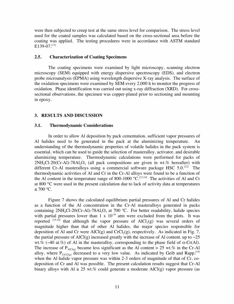
700 ºC. Figure 7 shows the calculated equilibrium partial pressures of Al and Cr halides
as a function of the Al concentration in the Cr-Al masteralloys generated in packs containing 2NH4Cl-20(Cr-Al)-78Al2O3 at 700 ºC. For better readability, halide species with partial pressures lower than 1 x 10⁻¹⁰ atm were excluded from the plots. It was reported [15,16] that although the vapor pressure of AlCl3(g) was several orders of magnitude higher than that of other Al halides, the major species responsible for deposition of Al and Cr were AlCl(g) and CrCl2(g), respectively. As indicated in Fig. 7, the partial pressure of AlCl(g) increased greatly with the increase of Al content, up to ~25 wt.% (~40 at.%) of Al in the masteralloy, corresponding to the phase field of -Cr(Al). The increase of PAlCl(g) became less significant as the Al content > 25 wt.% in the Cr-Al alloy, where PCrCl2(g) decreased to a very low value. As indicated by Geib and Rapp,[15] when the Al halide vapor pressure was within 2-3 orders of magnitude of that of Cr, co-deposition of Cr and Al was possible. The present calculation results suggest that Cr-Al binary alloys with Al 25 wt.% could generate a moderate AlCl(g) vapor pressure (as
12
compared to a pure Al masteralloy), where the complexity caused by Cr co-deposition could also be avoided.
Fig. 7. Equilibrium partial pressures of Al and Cr halides at 700 °C as a function of the Al content in Al-Cr masteralloys in packs of 2NH4Cl-20(Cr-Al)-78Al2O3 (wt.%).
3.2. As-Deposited Coatings 3.2.1. Aluminide Coatings Formed at 650 °C Using Pure Al Masteralloys
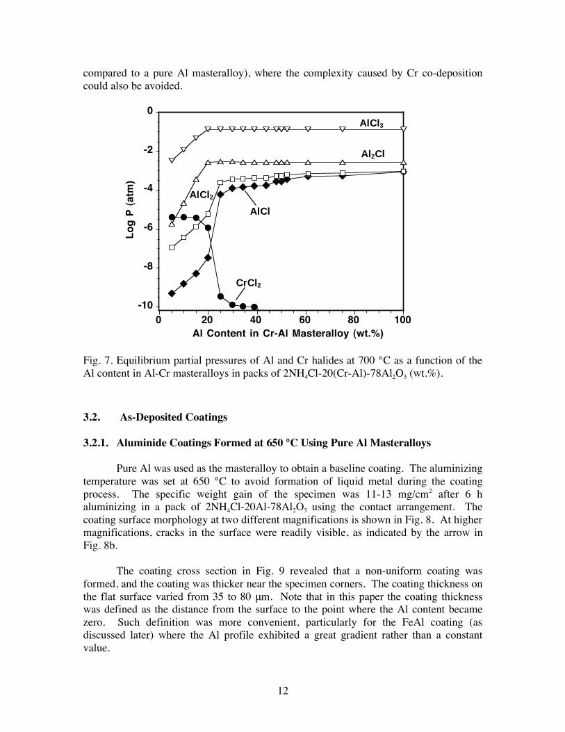
Pure Al was used as the masteralloy to obtain a baseline coating. The aluminizing temperature was set at 650 °C to avoid formation of liquid metal during the coating process. The specific weight gain of the specimen was 11-13 mg/cm2 after 6 h aluminizing in a pack of 2NH4Cl-20Al-78Al2O3 using the contact arrangement. The coating surface morphology at two different magnifications is shown in Fig. 8. At higher magnifications, cracks in the surface were readily visible, as indicated by the arrow in Fig. 8b.
The coating cross section in Fig. 9 revealed that a non-uniform coating was
formed, and the coating was thicker near the specimen corners. The coating thickness on the flat surface varied from 35 to 80 m. Note that in this paper the coating thickness was defined as the distance from the surface to the point where the Al content became zero. Such definition was more convenient, particularly for the FeAl coating (as discussed later) where the Al profile exhibited a great gradient rather than a constant value.
-10
-8
-6
-4
-2
0
0 20 40 60 80 100
Lo
g P
(at
m)
Al Content in Cr-Al Masteralloy (wt.%)
AlCl3
Al2Cl
AlCl2
AlCl
CrCl2

13
(a) (b) Fig. 8. Secondary electron SEM images of the coating surface fabricated in a pack of 2NH4Cl-20Al-89Al2O3 at 650 °C for 6 h. (a) and (b) were taken at two different magnifications.
Fig. 9. Backscattered electron SEM image of the cross section of the coating shown in Fig. 8.
10 μm 20 μm
500 μm
Coating Layer
14
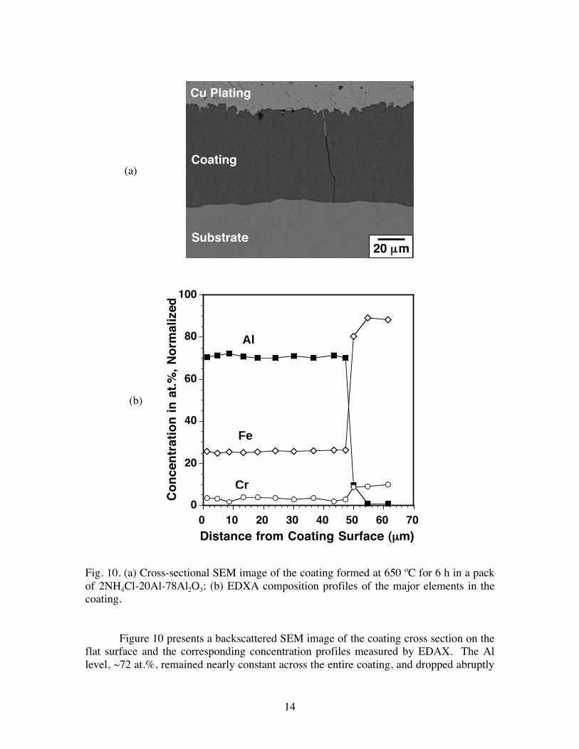
Fig. 10. (a) Cross-sectional SEM image of the coating formed at 650 ºC for 6 h in a pack of 2NH4Cl-20Al-78Al2O3; (b) EDXA composition profiles of the major elements in the coating.
Figure 10 presents a backscattered SEM image of the coating cross section on the
flat surface and the corresponding concentration profiles measured by EDAX. The Al level, ~72 at.%, remained nearly constant across the entire coating, and dropped abruptly
Substrate
Coating
Cu Plating
20 μm
(a)
0
20
40
60
80
100
0 10 20 30 40 50 60 70
Co
nce
ntr
atio
n i
n a
t.%
, N
orm
aliz
ed
Distance from Coating Surface ( μm)
Al
Fe
Cr
(b)
15
to zero at the coating/substrate interface. According to the Al-Cr-Fe phase diagram,[17] the solubility of Al in Fe2Al5 is in the range of 71.0 to 72.5 at.%, indicating that the coating consisted of Fe2Al5.
[18,19] The flat concentration profiles shown in Fig. 10b were resulted from the narrow stability range of the Fe2Al5 phase [20,21] and high Al diffusivity in this phase. The Al deposited at the coating surface diffused rapidly across the Fe2Al5 layer and reacted with the Fe from the substrate at the coating/substrate interface. Consequently, the Fe2Al5 coating was formed by inward diffusion of Al, which is typical for the high Al activity pack process.[20, 22, 23]
However, when the non-contact pack-specimen arrangement (Fig. 3b) with
porous alumina paper or foam was used, a significant variation in the specimen’s weight gain was noticed after aluminizing, and residues of alumina paper or foam were found attached to the specimen surface. During subsequent sample cleaning, sometimes coating spallation occurred with removal of the residues.
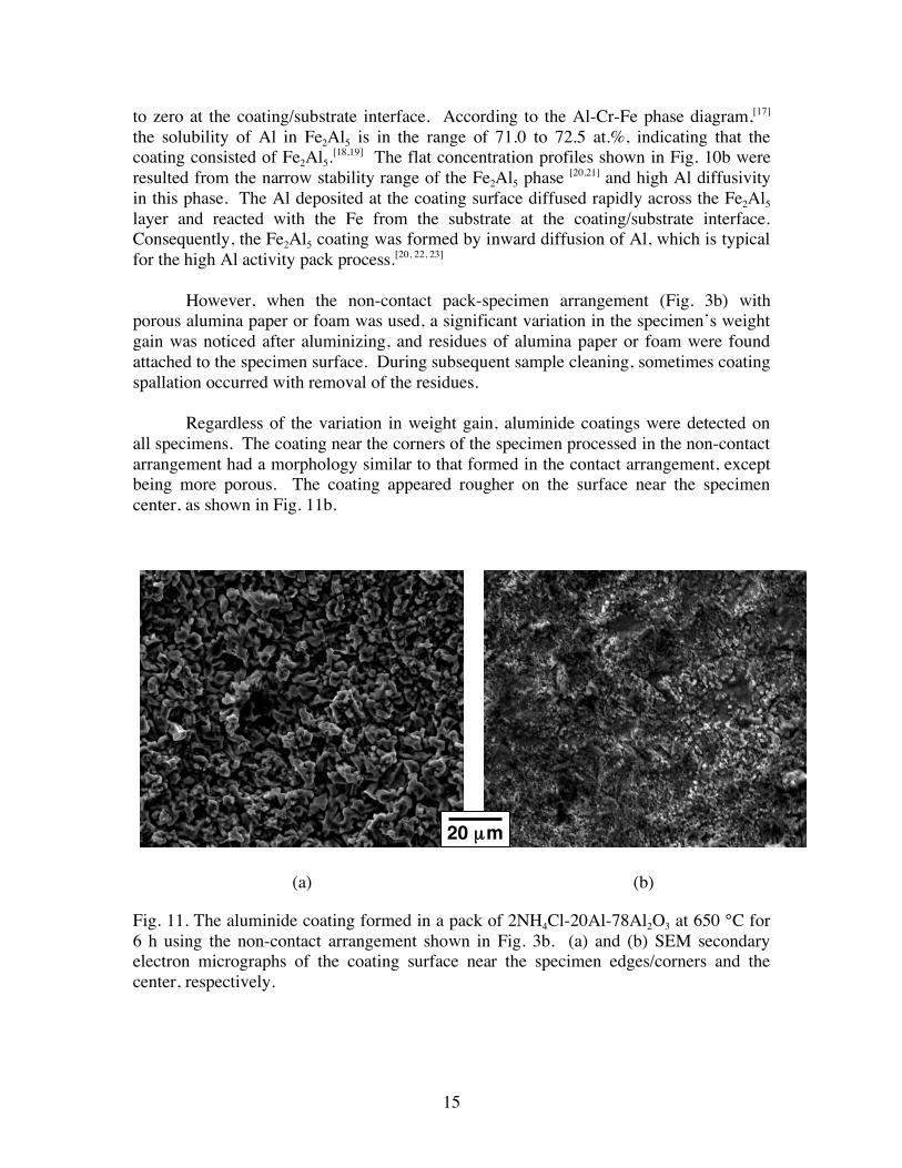
Regardless of the variation in weight gain, aluminide coatings were detected on all specimens. The coating near the corners of the specimen processed in the non-contact arrangement had a morphology similar to that formed in the contact arrangement, except being more porous. The coating appeared rougher on the surface near the specimen center, as shown in Fig. 11b.
(a) (b)
Fig. 11. The aluminide coating formed in a pack of 2NH4Cl-20Al-78Al2O3 at 650 °C for 6 h using the non-contact arrangement shown in Fig. 3b. (a) and (b) SEM secondary electron micrographs of the coating surface near the specimen edges/corners and the center, respectively.
20 μm
16
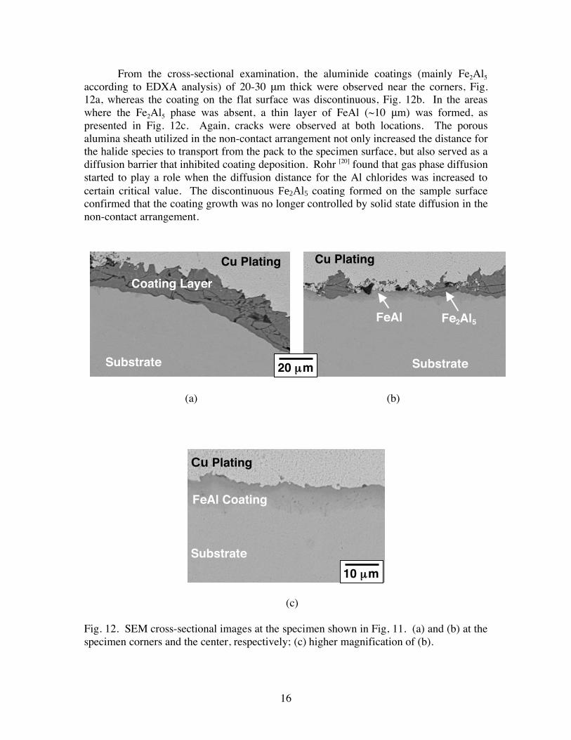
From the cross-sectional examination, the aluminide coatings (mainly Fe2Al5 according to EDXA analysis) of 20-30 m thick were observed near the corners, Fig. 12a, whereas the coating on the flat surface was discontinuous, Fig. 12b. In the areas where the Fe2Al5 phase was absent, a thin layer of FeAl (~10 m) was formed, as presented in Fig. 12c. Again, cracks were observed at both locations. The porous alumina sheath utilized in the non-contact arrangement not only increased the distance for the halide species to transport from the pack to the specimen surface, but also served as a diffusion barrier that inhibited coating deposition. Rohr [20] found that gas phase diffusion started to play a role when the diffusion distance for the Al chlorides was increased to certain critical value. The discontinuous Fe2Al5 coating formed on the sample surface confirmed that the coating growth was no longer controlled by solid state diffusion in the non-contact arrangement.
(a) (b)
(c)
Fig. 12. SEM cross-sectional images at the specimen shown in Fig, 11. (a) and (b) at the specimen corners and the center, respectively; (c) higher magnification of (b).
Cu Plating
Coating Layer
Substrate
Cu Plating
Substrate
Fe2Al5 FeAl
20 μm
Cu Plating
FeAl Coating
Substrate
10 μm
17
3.2.2. Aluminide Coatings Synthesized at 700 °C Using Cr-Al Masteralloys
Due to the irregular coatings formed in the non-contact arrangement, only contact assembly was employed when the Cr-Al binary masteralloys were used. Cr-25wt.%Al was first selected as the masteralloy based on the thermodynamic calculation, which exhibited an Al activity between the Cr5Al8 and Cr2Al alloys previously reported in the literature.[6,20] The aluminizing temperature was raised from 650 to 700 °C because of the higher melting temperature of the Cr-Al masteralloys.
3.2.2.1. Aluminide Coatings Using the Cr-25Al Masteralloy
Figure 13a shows the coating surface that was aluminized for 12 h in the pack of 2NH4Cl-15(Cr-25Al)-78Al2O3. EDAX analysis revealed that Fe2Al5 was formed on the coating surface, with ~72 at.% Al. The coating cross section shown in Fig. 13b exhibited a two-layer microstructure. The outer layer was Fe2Al5, <5 m thick, and the inner layer was ~10 m. The Al content in the inner layer gradually decreased from ~50 at.% to zero, Fig. 13c, suggesting that the FeAl phase was formed immediately beneath the Fe2Al5 layer and gradually changed to -Fe with Al and Cr in solid solution. Needle-like AlN precipitates (as pointed by the arrows) were observed underneath the inner layer, as previously reported.[5,20,24]
3.2.2.2. Aluminide Coatings Using the Cr-15Al Masteralloy
In order to completely eliminate the Fe2Al5 outer layer in the coating, the Al activity was further reduced by replacing Cr-25Al with the Cr-15Al masteralloy. The coating formed after 6 h aluminizing in the pack of 2NH4Cl-20(Cr-15Al)-78Al2O3 was ~9
m thick, containing < 50 at.% Al at the surface. The aluminizing time was then extended to 12 h to increase the coating thickness and to verify whether the coating growth followed a parabolic law.[25]
As illustrated in Fig. 14a, the coating displayed distinctive polyhedral-shaped
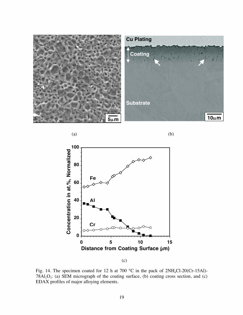
grains (<10 m) with prominent grain boundary ridges, in contrast to the Fe2Al5 coating shown in Fig. 13a. The current grain structure resembled the low-activity NiAl-based coatings formed on Ni-base superalloys at high temperatures,[26] except that the grain size was smaller in this case. A similar grain morphology was observed by Sivakumar et al. [27] for an aluminized plain carbon steel using binary Fe-Al masteralloys at 750 °C. The coating cross section and the EDAX composition profiles are given in Figs. 14b and c, respectively. The coating thickness was increased from 9 to ~12 m when the aluminizing time was extended from 6 to 12 h, implying a parabolic coating growth. The Al content at the surface was ~40 at.%, which again decreased gradually to zero through the coating thickness. The gradient in Al composition suggests that diffusion occurred in essentially a single-phase material at the aluminizing temperature.[28] According to the Al-Cr-Fe phase diagram,[17] it was clear that the FeAl phase formed near the coating surface. In addition, comparison of Figs. 10b and 14c shows that the Cr level in the FeAl coating was higher than that in Fe2Al5, suggesting that FeAl may have a higher solubility for Cr.

18
(a) (b)
(c) Fig. 13. The specimen coated for 12 h at 700 °C in the pack of 2NH4Cl-20(Cr-25Al)-78Al2O3: (a) SEM micrograph of the coating surface, (b) coating cross section, and (c) EDAX profiles of major alloying elements.
5μm
Cu Plating
Coating
Substrate
10μm
0
20
40
60
80
100
0 5 10 15 20
Distance from Coating Surface (μm)
Co
nce
ntr
atio
n i
n a
t.%
, N
orm
aliz
ed
Al
Fe
Cr
19
(a) (b)
(c)
Fig. 14. The specimen coated for 12 h at 700 °C in the pack of 2NH4Cl-20(Cr-15Al)-78Al2O3: (a) SEM micrograph of the coating surface, (b) coating cross section, and (c) EDAX profiles of major alloying elements.
0
20
40
60
80
100
0 5 10 15Distance from Coating Surface (μm)
Co
nce
ntr
atio
n i
n a
t.%
, N
orm
aliz
ed
Al
Fe
Cr
5μm 10μm
Cu Plating
Coating
Substrate
20
3.2.2.3. Effect of the Amount of Cr-15Al Masteralloys
The effect of the amount of Cr-15Al masteralloys on coating growth was investigated by employing a series of packs containing 2NH4Cl-x(Cr-15Al)-(98-x)Al2O3, where x = 10, 20, 30, 40, 50, 60, and 70 wt.%. As indicated in Table 2, the Al content at the coating surface was less than 50 at.% after 6h aluminizing for the seven packs at 700 °C, further confirming no Fe2Al5 formation with the Cr-15Al masteralloy.
The Al concentration profiles in the coatings obtained with various amount of
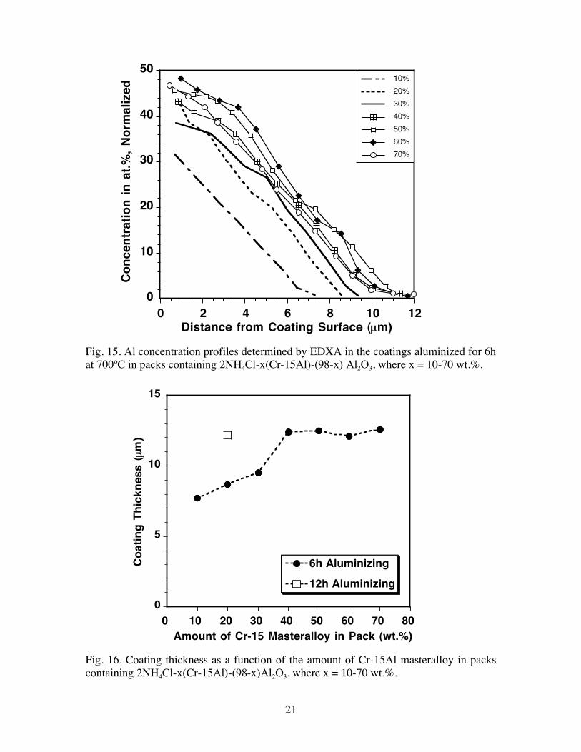
masteralloy are summarized in Fig. 15. The coating thickness as a function of the masteralloy amount is illustrated in Fig. 16. It was clear that with the initial increase of the Cr-15Al masteralloy, both the coating thickness and surface Al content increased, Fig. 15. However, when the amount of the masteralloy was greater than 40 wt.%, the increase became insignificant. The coating thickness remained in the range of 12-13 m when 40-70 wt.% of masteralloy was utilized.
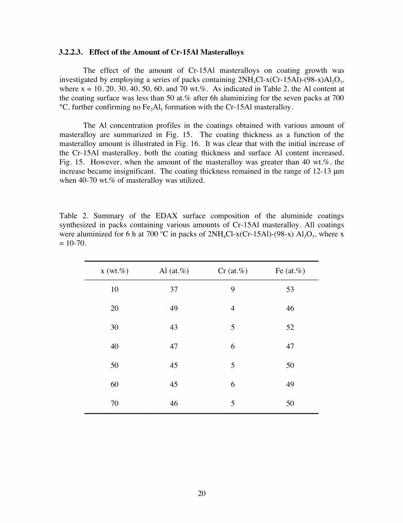
Table 2. Summary of the EDAX surface composition of the aluminide coatings synthesized in packs containing various amounts of Cr-15Al masteralloy. All coatings were aluminized for 6 h at 700 ºC in packs of 2NH4Cl-x(Cr-15Al)-(98-x) Al2O3, where x = 10-70.
x (wt.%) Al (at.%) Cr (at.%) Fe (at.%)
10 37 9 53
20 49 4 46
30 43 5 52
40 47 6 47
50 45 5 50
60 45 6 49
70 46 5 50
21
Fig. 15. Al concentration profiles determined by EDXA in the coatings aluminized for 6h at 700ºC in packs containing 2NH4Cl-x(Cr-15Al)-(98-x) Al2O3, where x = 10-70 wt.%.
Fig. 16. Coating thickness as a function of the amount of Cr-15Al masteralloy in packs containing 2NH4Cl-x(Cr-15Al)-(98-x)Al2O3, where x = 10-70 wt.%.
0
10
20
30
40
50
0 2 4 6 8 10 12
10%
20%
30%
40%
50%
60%
70%
Co
nce
ntr
atio
n i
n a
t.%
, N
orm
aliz
ed
Distance from Coating Surface ( μm)
0
5
10
15
0 10 20 30 40 50 60 70 80
6h Aluminizing
12h Aluminizing
Amount of Cr-15 Masteralloy in Pack (wt.%)
Co
atin
g T
hic
knes
s ( μ
m)
22
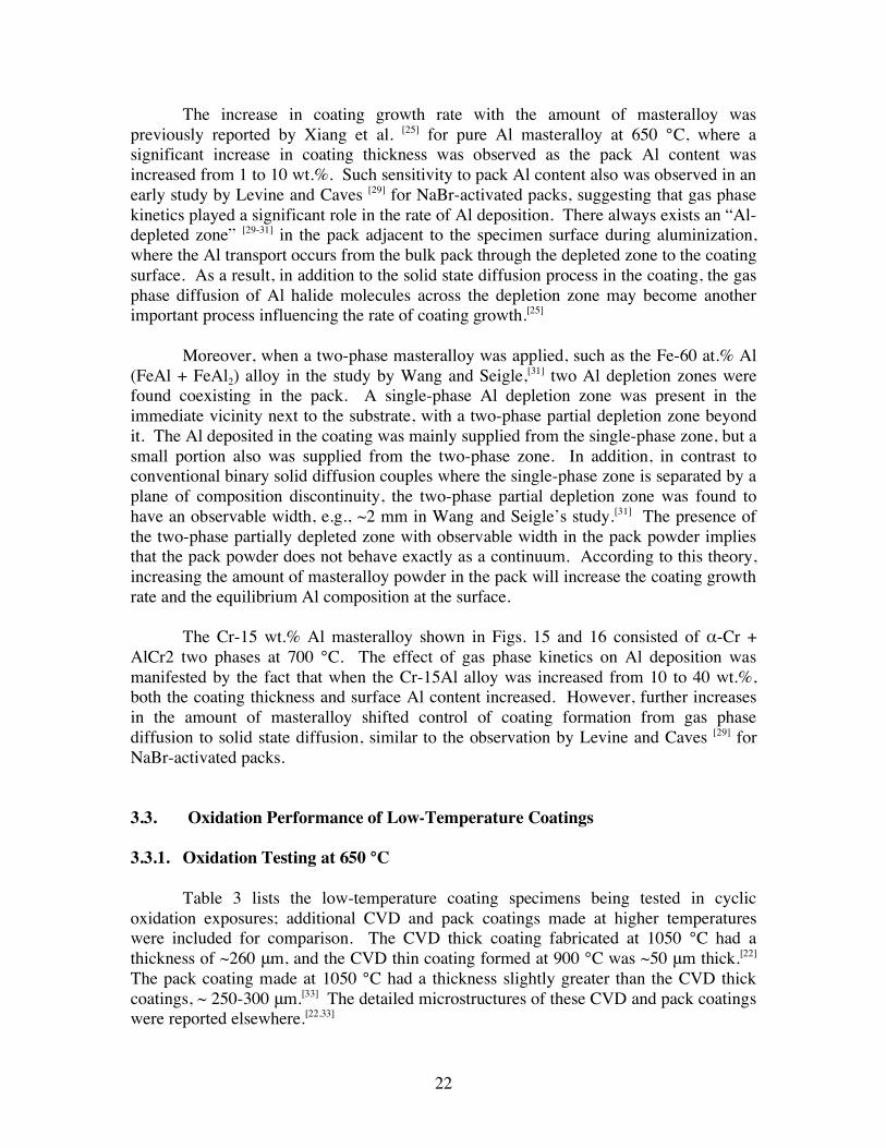
The increase in coating growth rate with the amount of masteralloy was previously reported by Xiang et al. [25] for pure Al masteralloy at 650 °C, where a significant increase in coating thickness was observed as the pack Al content was increased from 1 to 10 wt.%. Such sensitivity to pack Al content also was observed in an early study by Levine and Caves [29] for NaBr-activated packs, suggesting that gas phase kinetics played a significant role in the rate of Al deposition. There always exists an “Al-depleted zone” [29-31] in the pack adjacent to the specimen surface during aluminization, where the Al transport occurs from the bulk pack through the depleted zone to the coating surface. As a result, in addition to the solid state diffusion process in the coating, the gas phase diffusion of Al halide molecules across the depletion zone may become another important process influencing the rate of coating growth.[25]
Moreover, when a two-phase masteralloy was applied, such as the Fe-60 at.% Al
(FeAl + FeAl2) alloy in the study by Wang and Seigle,[31] two Al depletion zones were found coexisting in the pack. A single-phase Al depletion zone was present in the immediate vicinity next to the substrate, with a two-phase partial depletion zone beyond it. The Al deposited in the coating was mainly supplied from the single-phase zone, but a small portion also was supplied from the two-phase zone. In addition, in contrast to conventional binary solid diffusion couples where the single-phase zone is separated by a plane of composition discontinuity, the two-phase partial depletion zone was found to have an observable width, e.g., ~2 mm in Wang and Seigle’s study.[31] The presence of the two-phase partially depleted zone with observable width in the pack powder implies that the pack powder does not behave exactly as a continuum. According to this theory, increasing the amount of masteralloy powder in the pack will increase the coating growth rate and the equilibrium Al composition at the surface.
The Cr-15 wt.% Al masteralloy shown in Figs. 15 and 16 consisted of -Cr +
AlCr2 two phases at 700 °C. The effect of gas phase kinetics on Al deposition was manifested by the fact that when the Cr-15Al alloy was increased from 10 to 40 wt.%, both the coating thickness and surface Al content increased. However, further increases in the amount of masteralloy shifted control of coating formation from gas phase diffusion to solid state diffusion, similar to the observation by Levine and Caves [29] for NaBr-activated packs.
3.3. Oxidation Performance of Low-Temperature Coatings 3.3.1. Oxidation Testing at 650 °C
Table 3 lists the low-temperature coating specimens being tested in cyclic
oxidation exposures; additional CVD and pack coatings made at higher temperatures were included for comparison. The CVD thick coating fabricated at 1050 °C had a thickness of ~260 m, and the CVD thin coating formed at 900 °C was ~50 m thick.[22] The pack coating made at 1050 °C had a thickness slightly greater than the CVD thick coatings, ~ 250-300 m.[33] The detailed microstructures of these CVD and pack coatings were reported elsewhere.[22,33]

23
Table 3. The coating specimens tested in cyclic oxidation exposures at 650 and 700 °C in air + 10 vol.% H2O.
Coating ID (Aluminizing Temperature, Masteralloy)
Thickness (μm)
Surface Al (at.%)
Al Reservoir
(at.% x μm)
Coating Phase(s)
Oxidation Temperature
(°C)
Pack 700°C, Cr-25Al 4 / 12 72 / 50 588 Fe2Al5/FeAl 650, 700
Pack 700°C, Cr-15Al 12 40 240 FeAl 650, 700
Pack 1050˚C, Cr-15Al [33]
300 34 5100 FeAl 650
CVD 1050˚C [22] 260 26 3380 FeAl 650
CVD 900˚C [22] 50 18 450 FeAl 650, 700
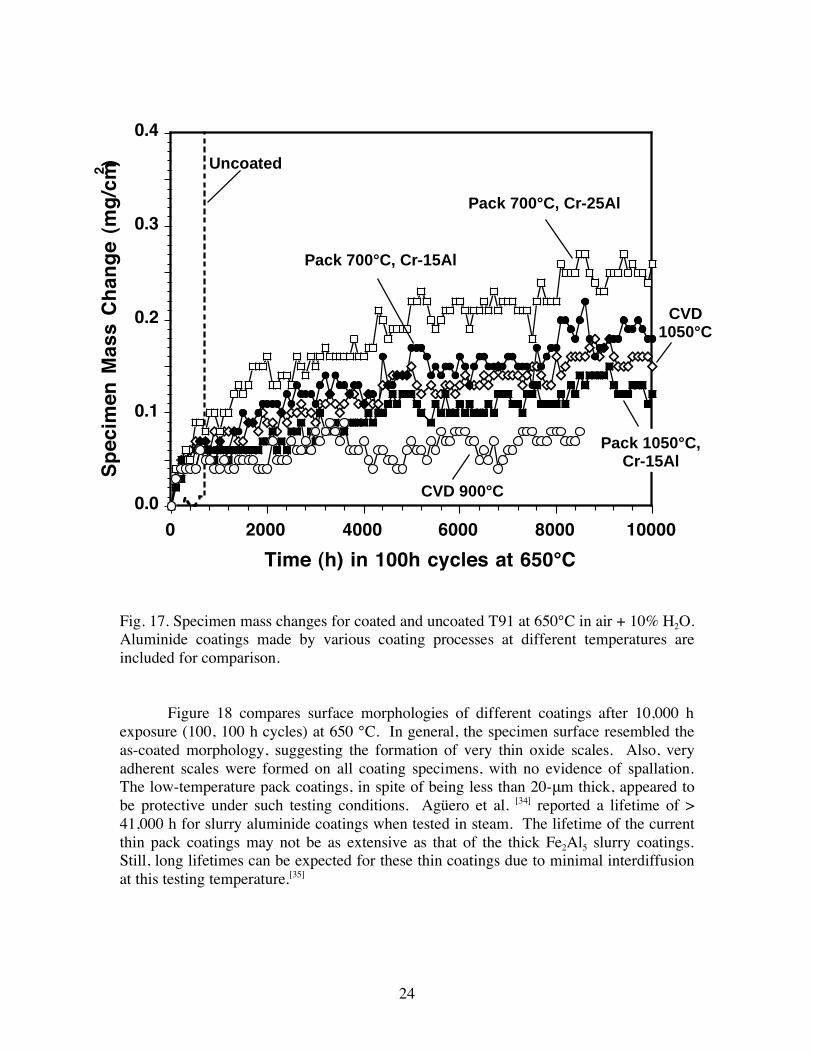
Figure 17 shows the mass change plots of coated and uncoated specimens
cyclically exposed at 650 °C in air + 10% water vapor. When the uncoated T91 alloy was tested in dry air at this temperature, a very low mass gain was observed, < 0.1 mg/cm2 after 5,000 h.[8] However, in the presence of 10% water vapor, the uncoated alloy underwent accelerated oxidation after an incubation period. Although not shown in Fig. 17, the formation of thick Fe-rich oxides resulted in a high mass gain of ~10.8 mg/cm2 after only 1,000 h exposure. The aluminide coatings synthesized by pack cementation or CVD prevented such accelerated attack. As shown in Fig. 17, all coated specimens registered very low mass gains. The pack coatings formed at 700 °C exhibited mass gains similar to the high-temperature CVD and pack coatings, up to ~ 10,000 h. The thick CVD and pack coatings synthesized at 1050 °C passed 10,000 h testing, and the CVD thin coating made at 900 °C passed more than 8,000 h at the moment (will be tested till failure).
24
Fig. 17. Specimen mass changes for coated and uncoated T91 at 650°C in air + 10% H2O. Aluminide coatings made by various coating processes at different temperatures are included for comparison.
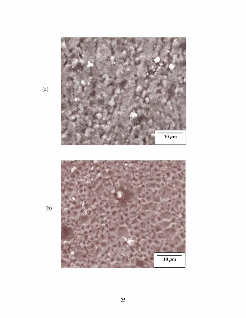
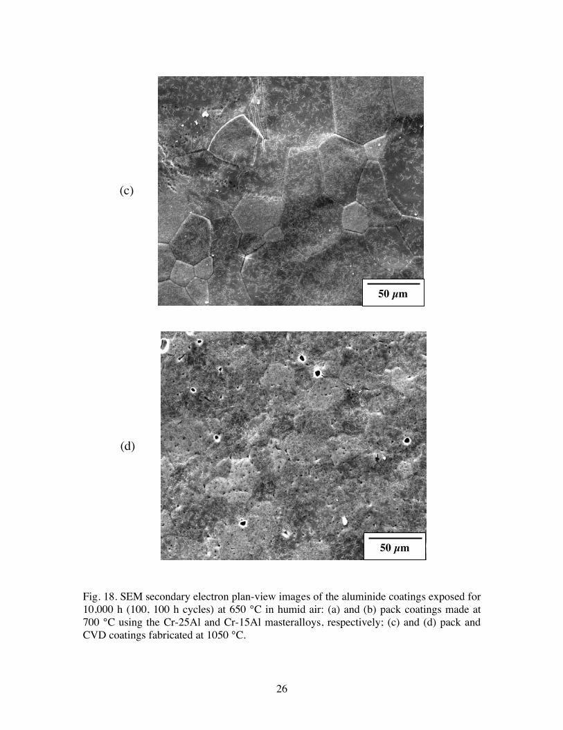
Figure 18 compares surface morphologies of different coatings after 10,000 h
exposure (100, 100 h cycles) at 650 °C. In general, the specimen surface resembled the as-coated morphology, suggesting the formation of very thin oxide scales. Also, very adherent scales were formed on all coating specimens, with no evidence of spallation. The low-temperature pack coatings, in spite of being less than 20- m thick, appeared to be protective under such testing conditions. Agüero et al. [34] reported a lifetime of > 41,000 h for slurry aluminide coatings when tested in steam. The lifetime of the current thin pack coatings may not be as extensive as that of the thick Fe2Al5 slurry coatings. Still, long lifetimes can be expected for these thin coatings due to minimal interdiffusion at this testing temperature.[35]
0.0
0.1
0.2
0.3
0.4
0 2000 4000 6000 8000 10000
Sp
ecim
en M
ass
Ch
ang
e (m
g/c
m2 )
Time (h) in 100h cycles at 650°C
CVD 900°C
CVD
1050°C
Pack 1050°C,
Cr-15Al
Pack 700°C, Cr-25Al
Pack 700°C, Cr-15Al
Uncoated
25
(a)
(b)
10 μm
10 μm
26
Fig. 18. SEM secondary electron plan-view images of the aluminide coatings exposed for 10,000 h (100, 100 h cycles) at 650 °C in humid air: (a) and (b) pack coatings made at 700 °C using the Cr-25Al and Cr-15Al masteralloys, respectively; (c) and (d) pack and CVD coatings fabricated at 1050 °C.
(c)
(d)
50 μm
50 μm
27
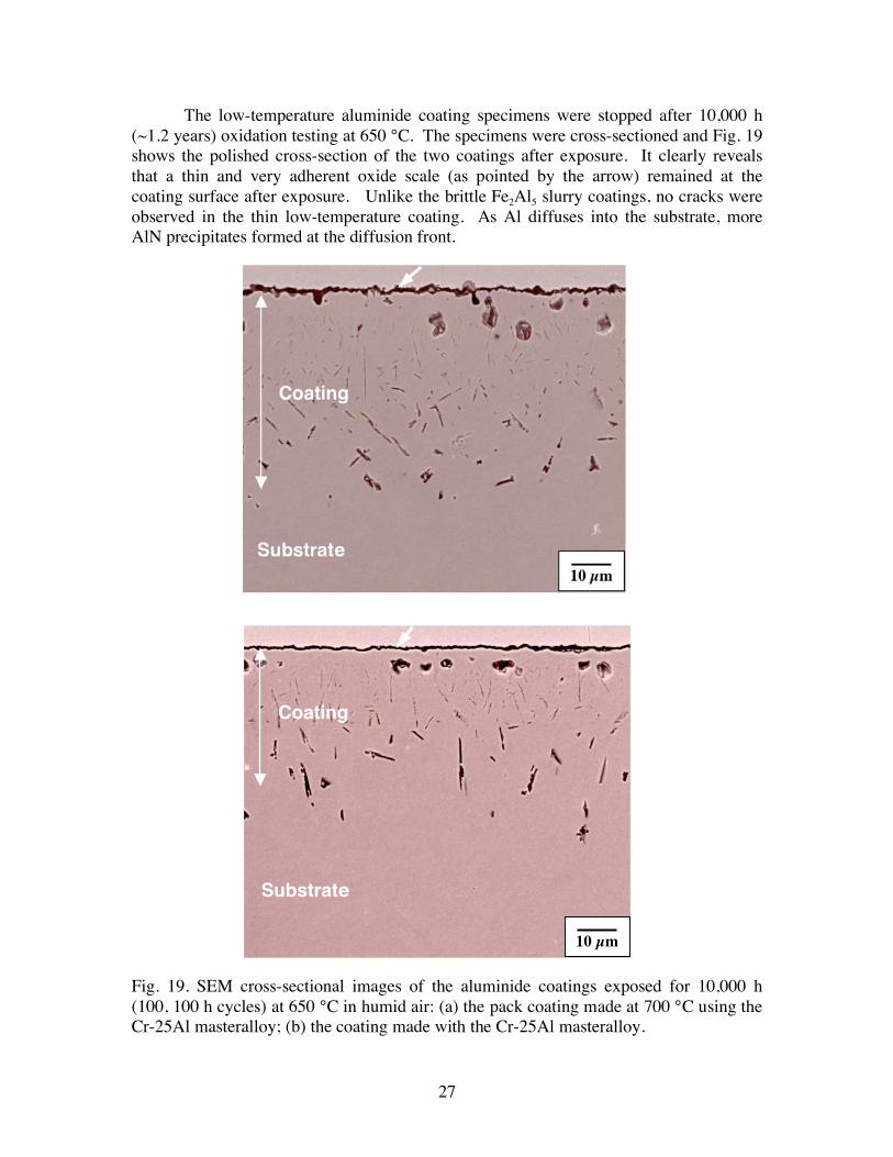
The low-temperature aluminide coating specimens were stopped after 10,000 h (~1.2 years) oxidation testing at 650 °C. The specimens were cross-sectioned and Fig. 19 shows the polished cross-section of the two coatings after exposure. It clearly reveals that a thin and very adherent oxide scale (as pointed by the arrow) remained at the coating surface after exposure. Unlike the brittle Fe2Al5 slurry coatings, no cracks were observed in the thin low-temperature coating. As Al diffuses into the substrate, more AlN precipitates formed at the diffusion front. Fig. 19. SEM cross-sectional images of the aluminide coatings exposed for 10,000 h (100, 100 h cycles) at 650 °C in humid air: (a) the pack coating made at 700 °C using the Cr-25Al masteralloy; (b) the coating made with the Cr-25Al masteralloy.
10 μm
Coating
Substrate
10 μm
Coating
Substrate
28
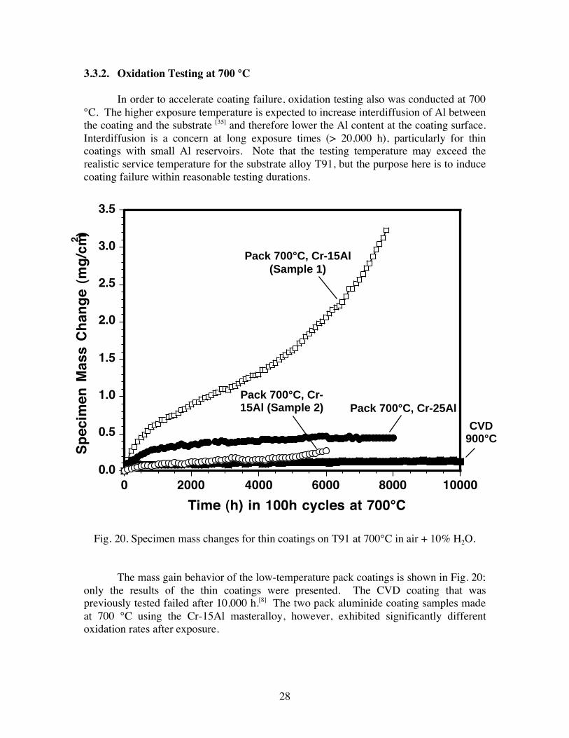
3.3.2. Oxidation Testing at 700 °C In order to accelerate coating failure, oxidation testing also was conducted at 700
°C. The higher exposure temperature is expected to increase interdiffusion of Al between the coating and the substrate [35] and therefore lower the Al content at the coating surface. Interdiffusion is a concern at long exposure times (> 20,000 h), particularly for thin coatings with small Al reservoirs. Note that the testing temperature may exceed the realistic service temperature for the substrate alloy T91, but the purpose here is to induce coating failure within reasonable testing durations.
Fig. 20. Specimen mass changes for thin coatings on T91 at 700°C in air + 10% H2O.
The mass gain behavior of the low-temperature pack coatings is shown in Fig. 20;
only the results of the thin coatings were presented. The CVD coating that was previously tested failed after 10,000 h.[8] The two pack aluminide coating samples made at 700 °C using the Cr-15Al masteralloy, however, exhibited significantly different oxidation rates after exposure.
0.0
0.5
1.0
1.5
2.0
2.5
3.0
3.5
0 2000 4000 6000 8000 10000
Sp
ecim
en M
ass
Ch
ang
e (m
g/c
m2 )
Time (h) in 100h cycles at 700°C
CVD
900°C
Pack 700°C, Cr-25Al
Pack 700°C, Cr-15Al
(Sample 1)
Pack 700°C, Cr-
15Al (Sample 2)
29
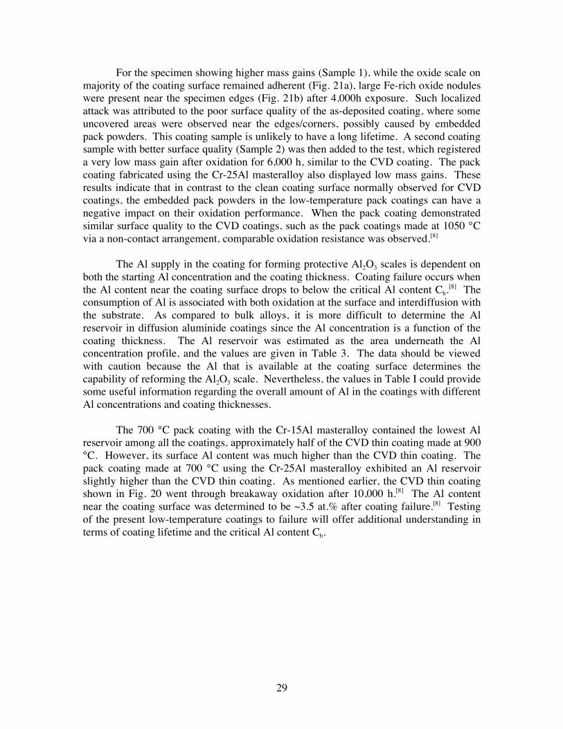
For the specimen showing higher mass gains (Sample 1), while the oxide scale on majority of the coating surface remained adherent (Fig. 21a), large Fe-rich oxide nodules were present near the specimen edges (Fig. 21b) after 4,000h exposure. Such localized attack was attributed to the poor surface quality of the as-deposited coating, where some uncovered areas were observed near the edges/corners, possibly caused by embedded pack powders. This coating sample is unlikely to have a long lifetime. A second coating sample with better surface quality (Sample 2) was then added to the test, which registered a very low mass gain after oxidation for 6,000 h, similar to the CVD coating. The pack coating fabricated using the Cr-25Al masteralloy also displayed low mass gains. These results indicate that in contrast to the clean coating surface normally observed for CVD coatings, the embedded pack powders in the low-temperature pack coatings can have a negative impact on their oxidation performance. When the pack coating demonstrated similar surface quality to the CVD coatings, such as the pack coatings made at 1050 °C via a non-contact arrangement, comparable oxidation resistance was observed.[8]
The Al supply in the coating for forming protective Al2O3 scales is dependent on
both the starting Al concentration and the coating thickness. Coating failure occurs when the Al content near the coating surface drops to below the critical Al content Cb.
[8] The consumption of Al is associated with both oxidation at the surface and interdiffusion with the substrate. As compared to bulk alloys, it is more difficult to determine the Al reservoir in diffusion aluminide coatings since the Al concentration is a function of the coating thickness. The Al reservoir was estimated as the area underneath the Al concentration profile, and the values are given in Table 3. The data should be viewed with caution because the Al that is available at the coating surface determines the capability of reforming the Al2O3 scale. Nevertheless, the values in Table I could provide some useful information regarding the overall amount of Al in the coatings with different Al concentrations and coating thicknesses.
The 700 °C pack coating with the Cr-15Al masteralloy contained the lowest Al
reservoir among all the coatings, approximately half of the CVD thin coating made at 900 °C. However, its surface Al content was much higher than the CVD thin coating. The pack coating made at 700 °C using the Cr-25Al masteralloy exhibited an Al reservoir slightly higher than the CVD thin coating. As mentioned earlier, the CVD thin coating shown in Fig. 20 went through breakaway oxidation after 10,000 h.[8] The Al content near the coating surface was determined to be ~3.5 at.% after coating failure.[8] Testing of the present low-temperature coatings to failure will offer additional understanding in terms of coating lifetime and the critical Al content Cb.
30
Fig. 21. SEM secondary electron plan-view images of the pack coating made at 700 °C using the Cr-15Al masteralloy after 4,000 h at 700 °C in humid air: (a) majority of the coating surface and (b) Fe-rich nodules formed near the edges (as pointed by the arrows).
(a)
(b)
20 μm
200 μm
31
3.4. Effect of Low-Temperature Coatings on Creep Resistance of Coated Alloys The creep behavior of uncoated and coated T91 specimens was tested at 650 °C to
investigate the effect of aluminide coatings on the creep resistance of the coated alloy.
Representative coatings (the first three groups listed in Table 3) were included in the
creep test. The first two coatings were the low-temperature pack coating developed in
this project. The third group represented the thick aluminide coatings synthesized at high
temperatures, which was similar to the CVD coatings made at the same temperature.
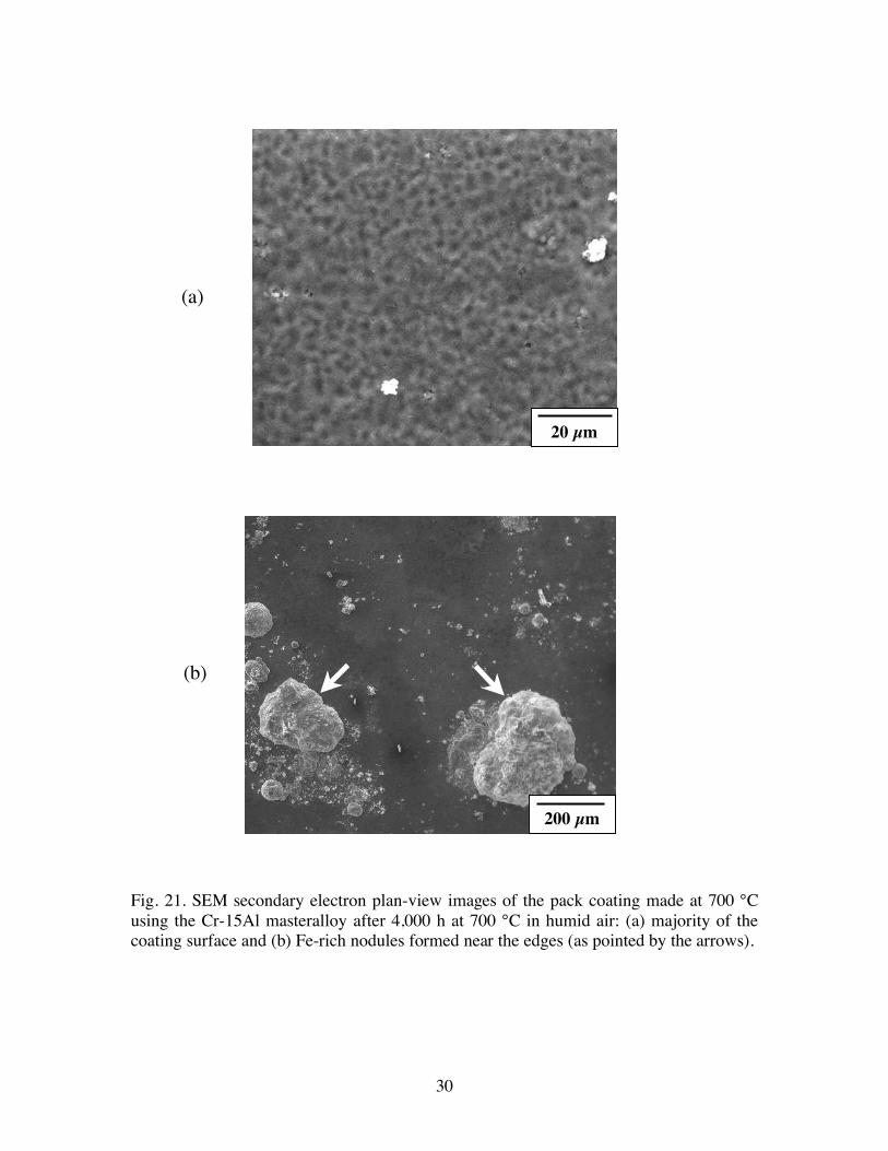
Figure 22 shows an as-coated dog-bone creep specimen that was aluminized at 700 °C
for 12 h. The coating was uniform and covered the entire specimen surface.
Fig. 22. The dog-bone specimen that was aluminized in a pack of NH4Cl-20(Cr15Al)-78Al2O3 for 12 h at 700 °C.
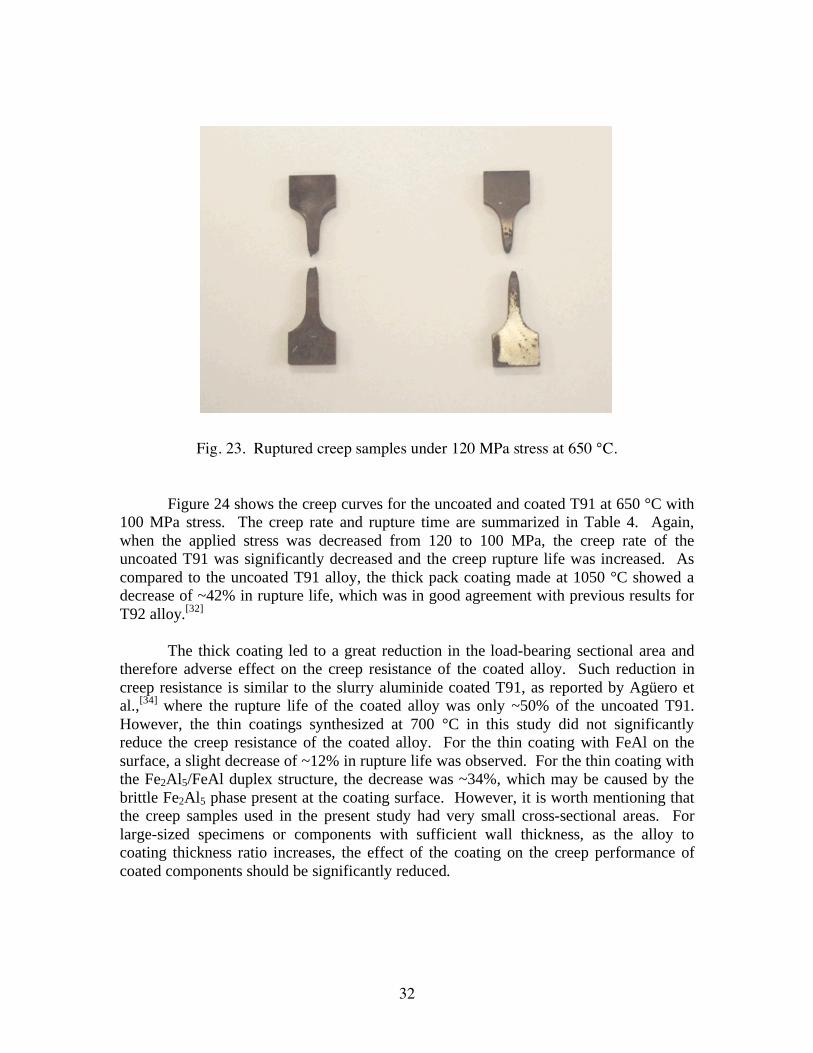
Initial testing was conducted on uncoated T91 specimens at a stress level of 120
MPa to establish a baseline and verify the tester alignment in a minimal amount of time. As indicated in Fig. 23, both samples ruptured within the gauge section after ~65 h. The steady state creep rates were ~ 2.2 x 10⁻⁴ and 2.5 x 10⁻⁴ h-1, respectively. The creep rate
was determined based on the slope of the secondary creep regime. Once good repeatability was achieved, the stress level was changed to 100 MPa, which was close to the service conditions for the substrate alloy.[4]
32
Fig. 23. Ruptured creep samples under 120 MPa stress at 650 °C. Figure 24 shows the creep curves for the uncoated and coated T91 at 650 °C with
100 MPa stress. The creep rate and rupture time are summarized in Table 4. Again,
when the applied stress was decreased from 120 to 100 MPa, the creep rate of the
uncoated T91 was significantly decreased and the creep rupture life was increased. As
compared to the uncoated T91 alloy, the thick pack coating made at 1050 °C showed a
decrease of ~42% in rupture life, which was in good agreement with previous results for
T92 alloy.[32]
The thick coating led to a great reduction in the load-bearing sectional area and
therefore adverse effect on the creep resistance of the coated alloy. Such reduction in
creep resistance is similar to the slurry aluminide coated T91, as reported by Agüero et
al.,[34]
where the rupture life of the coated alloy was only ~50% of the uncoated T91.
However, the thin coatings synthesized at 700 °C in this study did not significantly
reduce the creep resistance of the coated alloy. For the thin coating with FeAl on the
surface, a slight decrease of ~12% in rupture life was observed. For the thin coating with
the Fe2Al5/FeAl duplex structure, the decrease was ~34%, which may be caused by the
brittle Fe2Al5 phase present at the coating surface. However, it is worth mentioning that
the creep samples used in the present study had very small cross-sectional areas. For
large-sized specimens or components with sufficient wall thickness, as the alloy to
coating thickness ratio increases, the effect of the coating on the creep performance of
coated components should be significantly reduced.
33
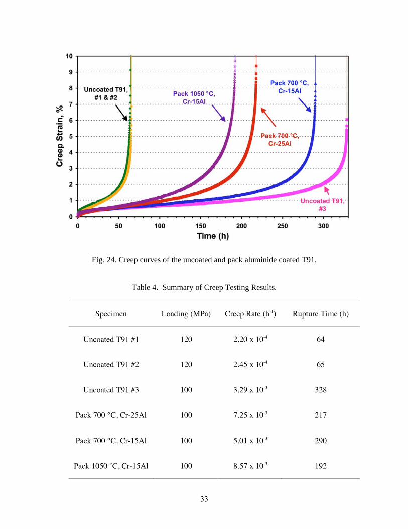
Fig. 24. Creep curves of the uncoated and pack aluminide coated T91.
Table 4. Summary of Creep Testing Results.
Specimen Loading (MPa) Creep Rate (h-1) Rupture Time (h)
Uncoated T91 #1 120 2.20 x 10⁻⁴ 64
Uncoated T91 #2 120 2.45 x 10⁻⁴ 65
Uncoated T91 #3 100 3.29 x 10⁻³ 328
Pack 700 °C, Cr-25Al 100 7.25 x 10⁻³ 217
Pack 700 °C, Cr-15Al 100 5.01 x 10⁻³ 290
Pack 1050 ˚C, Cr-15Al 100 8.57 x 10⁻³ 192
34
Figure 24 shows the creep curves for the uncoated and coated T91 at 650 °C with
100 MPa stress. The creep rate and rupture time are summarized in Table 4. When the
applied stress level was reduced from 120 to 100 MPa, the creep rate of the uncoated T91
decreased nearly one order, and the creep rupture life was significantly increased.
As compared to the uncoated T91, the thick pack coating made at 1050 °C
exhibited a creep rate that was 2.6 times of the bare alloy (8.57 x 10⁻³
vs. 3.29 x 10⁻³
h-1
)
and a decrease of ~42% in rupture life. This result was in good agreement with previous
research on another 9Cr alloy, T92.[32]
However, the thin coatings synthesized at 700 °C did not significantly reduce the
creep resistance of the coated alloy. For the thin coating with the Fe2Al5/FeAl duplex
structure (Fig. 13) that was fabricated in the pack containing Cr-25Al masteralloy, a 34%
reduction of rupture life was observed. This was probably caused by the brittle Fe2Al5
phase present at the coating surface.
The thin pack coating made in the Cr-15Al pack at 700 °C showed the best creep
resistance among the three groups of coatings that were tested. This coating consisted of
FeAl near the surface, as shown in Fig. 14 in the previous section. A slight decrease,
~12%, in rupture life was noticed as compared to the uncoated alloy.
For the thin coating with the Fe2Al5/FeAl duplex structure, the decrease was
~34%, which may be caused by the brittle Fe2Al5 phase present at the coating surface.
However, it is worth mentioning that the creep samples used in the present study had very
small cross-sectional areas. For large-sized specimens or components with sufficient
wall thickness, as the alloy to coating thickness ratio increases, the effect of the coating
on the creep performance of coated components should be significantly reduced.
The thick coating led to a great reduction in the load-bearing sectional area and
therefore adverse effect on the creep resistance of the coated alloy. Such reduction in
creep resistance is similar to the slurry aluminide coated T91, as reported by Agüero et
al.,[34]
where the rupture life of the coated alloy was only ~50% of the uncoated T91.
However, the thin coatings synthesized at 700°C in this study did not significantly
reduce the creep resistance of the coated alloy. For the thin coating with FeAl on the
surface, a slight decrease of ~12% in rupture life was observed. For the thin coating with
the Fe2Al5/FeAl duplex structure, the decrease was ~34%, which may be caused by the
brittle Fe2Al5 phase present at the coating surface. However, it is worth mentioning that
the creep samples used in the present study had very small cross-sectional areas. For
large-sized specimens or components with sufficient wall thickness, as the alloy to
coating thickness ratio increases, the effect of the coating on the creep performance of
coated components should be significantly reduced.
35
4. CONCLUSIONS Thermodynamic calculations were carried out by using commercial software HSC
5.0 for a series of packs containing Cr-Al binary masteralloys with various Al concentrations. The calculation results indicate that the equilibrium partial pressures of Al halides at 700 °C were a function of Al content in the Cr-Al alloys. Masteralloys Cr-25Al and Cr-15Al were selected for fabrication of aluminide coatings via pack cementation, with the aim of eliminating brittle Al-rich intermetallic phases in the coating. In contrast to pure Al masteralloy which led to the formation of Fe2Al5 coatings at 650 °C, a coating consisting of a thin Fe2Al5 outer layer and an FeAl inner layer was achieved at 700 ºC with the Cr-25Al masteralloy. By switching to the Cr-15Al masteralloy, thin FeAl coatings (~12 m) containing < 50 at.% Al were synthesized at 700 ºC. The effect of the amount of Cr-15Al masteralloys on coating growth was studied by employing packs containing 2NH4Cl-x(Cr-15Al)-(98-x)Al2O3, where x = 10, 20, 30, 40, 50, 60, and 70 wt.%. It was noticed that when the amount of Cr-15Al masteralloy was increased from 10 to 40 wt.%, both coating thickness and surface Al content increased, indicating that gas phase kinetics played a significant role in the rate of Al deposition. However, with further increase in the amount of the masteralloy, solid state diffusion became rate-limiting.
The long-term oxidation performance of the aluminide coatings synthesized at
700 °C with Cr-25Al and Cr-15Al masteralloys was evaluated in the water vapor environment at 650-700 °C. The low-temperature pack coatings demonstrated excellent oxidation resistance at 650 °C in humid air after ~1.2 yr testing. Longer lifetimes can be expected for these thin coatings due to minimal interdiffusion at this testing temperature. Exposure at 700 °C was conducted to accelerate coating failure via increased interdiffusion of Al with the substrate alloy. The coatings also exhibited good oxidation protection up to 6,000-8,000 h at 700 °C, with longer testing needed for coating failure to occur. Furthermore, the oxidation results indicate that in addition to the Al reservoir (as determined by the Al content and coating thickness), the initial coating surface quality had a significant impact on the oxidation behavior.
In addition, the effect of various pack aluminide coatings on the creep resistance
of coated T91 was investigated. Three representative types of coatings with different thicknesses, Al concentrations and phase constituents were included in the creep test. The creep experiments were performed at 650 °C in air at uniaxial stress levels of 100-120 MPa. The thick aluminide coating made at 1050 °C showed a considerable reduction (~42%) in the creep rupture life of the coated alloy, due to the decrease of the load-bearing section. In contrast, the low-temperature thin coatings developed in this project did not significantly reduce the creep resistance of the coated T91 alloy, particularly the thin FeAl coating synthesized at 700°C using the Cr-15Al masteralloy.
36
5. ACKNOWLEDGEMENTS The PI would like to acknowledge B. A Pint and I. G. Wright at Oak Ridge
National Laboratory (ORNL) for fruitful discussions. The PI also thanks G. W. Garner and T. M. Brummett at ORNL for assisting with the oxidation tests. This research was sponsored by the U.S. Department of Energy, Advanced Coal Research at U.S. Colleges and Universities, under grant No. DE-FG26-06NT42674.
37
6. REFERENCES
1. R. Viswanathan, Adv. Mater. Processes, 162 (2004) 73.
2. R. Viswanathan and W. Bakker, J. Mater. Eng. Performance, 10 (2001) 81.
3. R. Bianco and R. A. Rapp, “Pack cementation diffusion coatings”, in Metallurgical and Ceramic Protective Coatings, K. H. Stern, Ed., Chapman & Hall, London, 1996, pp. 236.
4. P. J. Ennis, A. Zielinska-Lipiec, O. Wachter, A. Czyrska-Filemonowicz, Acta Mater., 45 (1997) 4901.
5. A. Agüero, R. Muelas, A. Paster, and S. Osgerby, Surf. Coat. Technol., 200 (2005) 1219.
6. V. Rohr, M. Schütze, E. Fortuna, D.N. Tsipas, A. Milewska and F. J. Pérez, Mater. Corros., 56 (2005) 874.
7. B.A. Pint, Y. Zhang, P.F. Tortorelli, J.A. Haynes, and I.G. Wright, Mater. High Temp., 18 (2001) 185.
8. B.A. Pint, Y. Zhang, L.R. Walker, and I.G. Wright, Surf. Coat. Technol., 202 (2007) 637.
9. S.C. Kung and R.A. Rapp, J. Electrochem. Soc., 135 (1988) 731.
10. Y. Zhang, Y.Q. Wang, and B.A. Pint, NACE Paper 07-468, Houston, TX, presented at NACE Corrosion 2007, Nashville, TN, March 2007.
11. ASTM standard
12. HSC Chemistry 5.0 for Windows – Chemical Reaction and Equilibrium Software with Extensive Thermochemical Database, Outokumpu Research Oy, Pori, Finland.
13. W. Johnson, K. Komarek, and E. Miller, Trans. Met. Soc. AIME, 242 (1968) 1685.
14. B. Nciri and L. Vandenbulcke, J. Less-Common Metals, 95 (1983) 55.
15. F.D. Geib and R.A. Rapp, Oxid. Met., 40 (1993) 213.
16. W. Da Costa, B. Gleeson, and D.J. Young, J. Electrochem. Soc., 141 (1994) 1464.
17. Al-Cr-Fe ternary phase diagram, in Ternary Alloys – A comprehensive Compendium of Evaluated Constitutional Data and Phase Diagrams, Vol. 5, Eds. G. Petzow and G. Effenberg, VCH Verlagsgesellschaft, Weinheim & VCH
38
Publishers, New York, 1993.
18. V. Rohr and M. Schütze, Mater. Sci. Forum, 461-464 (2004) 401.
19. Z.D. Xiang and P.K. Datta, J. Mater. Sci., 40 ( 2005) 1959.
20. V. Rohr, “Developpement de revetements pour les aciers D’echangeurs thermiques et amelioration de leur resistance a la corrosion en environnement simulant les fumees de combustion de charbon,” Ph.D. Dissertation, Karl-Winnacker-Institut, DECHEMA .V., Germany, 2005.
21. Al-Fe binary phase diagram, in Binary Alloy Phase Diagrams, T.B. Massalski, H. Okamoto, P.R. Subramanian, and L. Kacprzak, eds., ASM, 1990.
22. Y. Zhang, B.A. Pint, K.M. Cooley, and J.A. Haynes, Surf. Coat. Technol., 202 (2008) 3839.
23. G.W. Goward and D.H. Boone, Oxid. Met. 3 (1971) 475.
24. Y. Zhang, B.A. Pint, K.M. Cooley, and J.A. Haynes, Surf. Coat. Technol., 200 (2005) 1231.
25. Z.D. Xiang and P.K. Datta, Metall. Mater. Trans., 37A (2006) 3359.
26. W. Y. Lee, Y. Zhang, I. G. Wright, B. A. Pint, and P. K. Liaw, Metall. Mater. Trans., 29A (1998) 833.
27. R. Sivakumar and E.J. Rao, Oxid. Met., 17 (1982) 391.
28. H.C. Akuezue and D.P. Whittle, Met. Sci., 17 (1983) 27.
29. S.R. Levine and R.M. Caves, J. Electrochem. Soc., 121 (1974) 1051.
30. B.K. Gupta and L.L. Seigle, Thin Solid Films, 73 (1980) 365.
31. T.H. Wang and L.L. Seigle, Mater. Sci. Eng., 108A (1989) 253.
32. S. Dryepondt, Y. Zhang, and B.A. Pint, Surf. Coat. Technol., 201 (2006) 3880.
33. Y. Q. Wang, “Aluminide Coatings on Fe-9Cr-1Mo Steel Synthesized by Pack Cementation for Power Generation Applications”, Ph.D. Dissertation, Tennessee Tech University, December, 2006.
34. A. Agüero, R. Muelas, M. Gutiérrez, R. Van Vulpen, S. Osgerby, J. P. Banks, Surf. Coat. Technol. 201 (2007) 6253.
35. Y. Zhang, A. P. Liu, and B. A. Pint, Mater. Corros., 58 (2007) 751.