Embed Size (px)
Citation preview
International Journal of Advance Robotics & Expert Systems (JARES) Vol.1, No.3
1
A NOVEL NAVIGATION STRATEGY FOR AN UNICYCLE
MOBILE ROBOT INSPIRED FROM THE DUCK
WALKING (GYROSCOPIC NAVIGATION)
Radwen Bahri1, Rahma Boucetta2 And Saloua Bel Hadj Ali Naoui3
1University Of Gabes, National Engineering School Of Gabes, Tunisia Research Lab. Modeling, Analysis And Control Of Systems (MACS) LR16ES22
2Sciences Faculty of Sciences, University of Sfax, Soukra Avenue, 3000 Sfax Tunisia 3Preparatory Institute for Engineering Studies, El Manar University, Tunis , Tunisia
ABSTRACT This paper deals with the design and the implementation of a novel navigation strategy for an unicycle mobile robot. The strategy of navigation is inspired from nature (the duck walking) in the closed loop. Therefore, a single sensor (gyroscope) is used to determine the pose of the robot, hence the proposed name "gyroscopic navigation". A global presentation of the novel strategy and the robot and with its different components are given. An experimental identification for the useful parameters are then exhibited. Moreover, the controller design strategy and the simulation results are given. Finally, real time experiments are accomplished to valid the simulation results. KEYWORDS Robot navigation, navigation strategy, Robot pose, angular position
1. INTRODUCTION Nowadays, a great variety of navigation strategies have been developed. Nevertheless, these strategies are limited to odometry in order to determine the position and the speed of the robot. In this regard, the simplest way to measure displacement and speed of a mobile robot is to place an encoder in the drive motors in the active wheels [1, 2, 3, 4] or even in additional passive wheels [5]. However, measurements given by the encoder suffer from many problems such as accurate wheel diameter estimation, wheel wear and slippage and uncertainty in the determination of the contact point with the floor. Actually, there are various techniques for measuring the position rather than odometry method. Doppler navigation systems use the doppler effect to determine the speed of vehicle. The principle of the process is based on the doppler shift in frequency observed when radiated energy reflects a surface that is moving with respect to the emitter. Those systems cause errors in detecting true ground, speed and temperature. They also affect the velocity of sound and oscillation frequency of a crystal oscillator which impact the velocity given by the sensor [6] and require the existence of a reflection surface. Furthermore, the global positioning systems gps suffer from signal masking in areas such as densely treed streets and tunnels [7][10] as well as sampling rate [9]. A novel navigation strategy is proposed to overcome these problems. This paper is arranged as shown. Section II presents the structural design and the strategy principle of the robot navigation. Section III presents mathematical model, simulation results, practical validations and specifications for the novel strategy. Finally, the paper is ended with a conclusion.
International Journal of Advance Robotics & Expert Systems (JARES) Vol.1, No.3
2
2. THE ROBOT DESIGN AND ARCHITECTURE 2.1. Robot design The robot used in this study is an unicycle robot as shown in the following figure 1.
Figure 1: Robot architecture.
2.2. Robot architecture The Robot comprises a microprocessor to implement a neural network for the path planning which requires high calculation capacity and a microcontroller for interface with IMU ( inertial measurement unit ) and the power board managing the energy required for the operation of the actuators.
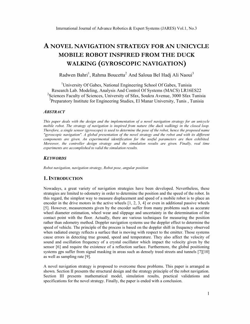
3. NAVIGATION STRATEGY This section describes the origin of idea from the duck walk to develop a functional analysis and to show a mathematical description of the evolution of the robot in the plan. 3.1. Functional Analysis An example of a duck walk is given in the figure 2.
Figure 2: The duck walk
International Journal of Advance Robotics & Expert Systems (JARES) Vol.1, No.3
3
Where O is the center of gravity and (x,y) are the Cartesian coordinates in the plane. It is assumed that the evolution medium of duck is a non-inclined plane, the direction is constant and we are interested in the evolution of the Y-coordinate. So, we obtain:
( 1) = ( )y k y k y (1) where
= .sin( ( ))y l (2) and
( 1) = ( ) ( )k k (3) The same model is given on the x-axis
( 1) = ( )x k x k x (4) where
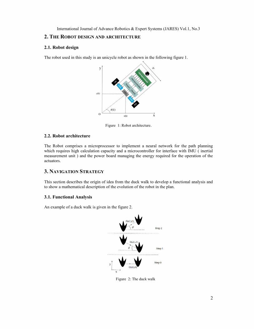
= .sin( ( / 2))x l (5) 3.2 Path Planning
It is assumed that the evolution medium of the duck is a non-inclined plane, xf > x0 and yf > y0. The new strategy relies on the change of the angular position of the driving wheels, one of which plays the role of the center of rotation and the other wheel moves.
The robot posture in base frame is given by ( ) = [ ( ) ( ) ( )]Tq k x k y k k .
We assume that the initial pose of the robot is = [ ]Ti i i iq x y and the final pose is
= [ ]Tf f f fq x y . The trajectory is divided into two parts: the first one is a straight line parallel
to the axis Y [ Dy ] with
= [ ]i fDy y y L (6)
Then Dy is divided to n steps sY with
= . sDy n Y (7)
sY is composed of 3 sub-steps as shown in Fig.3
Figure 3: Y evolution
We pose = 1 2 3sY y y y (8)
International Journal of Advance Robotics & Expert Systems (JARES) Vol.1, No.3
4
where 1 = .sin( )y L (9)
2 = 2 .sin( )y L (10)
3 = .sin( )y L (11)
The second part of the trajectory is a straight line parallel to the axis X [ Dx ] with :
= [ ]i fDx x x L (12)
Then Dx is divided to n steps sX with :
= . sDx n X (13)
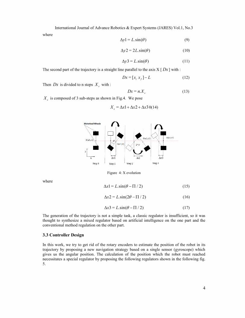
sX is composed of 3 sub-steps as shown in Fig.4. We pose
= 1 2 3sX x x x 0(14)
Figure 4: X evolution
where 1 = .sin( / 2)x L (15)
2 = .sin(2 / 2)x L (16)
3 = .sin( / 2)x L (17)
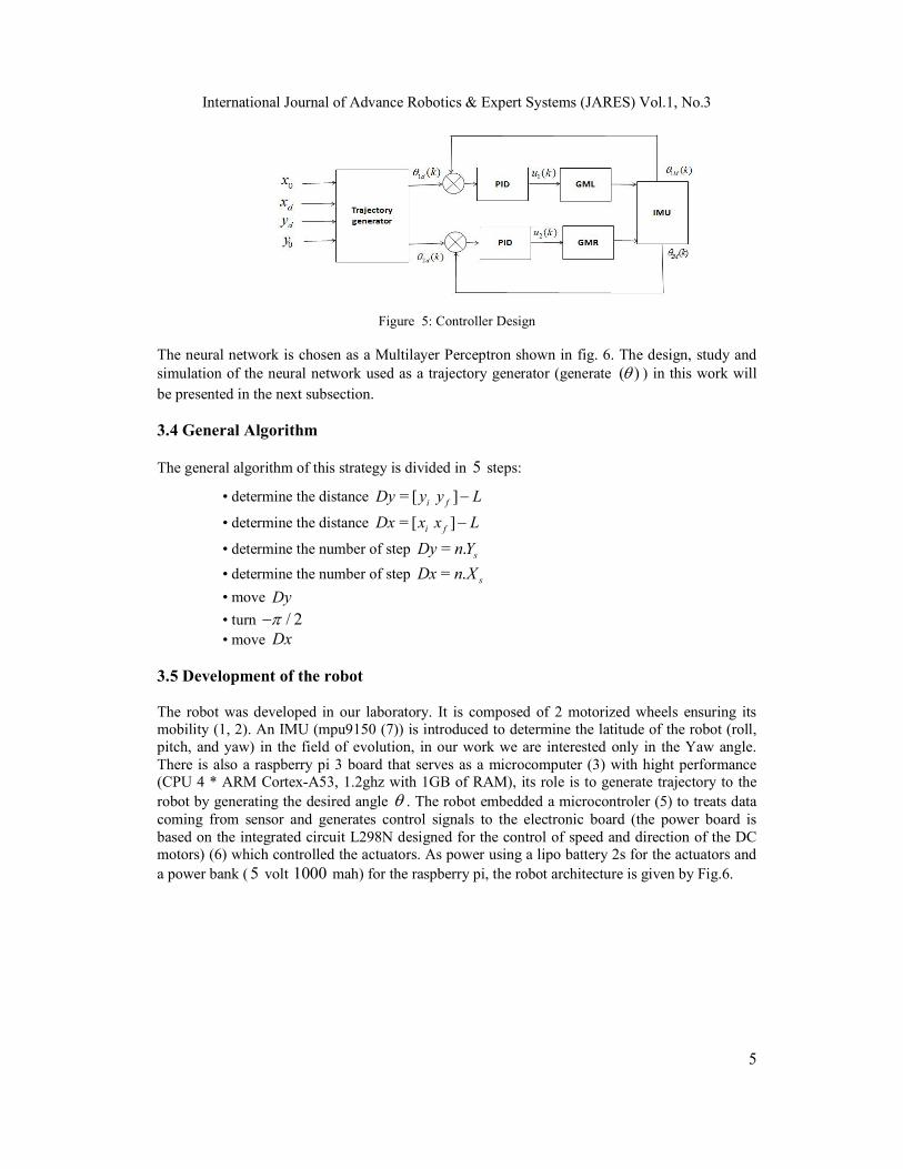
The generation of the trajectory is not a simple task, a classic regulator is insufficient, so it was thought to synthesize a mixed regulator based on artificial intelligence on the one part and the conventional method regulation on the other part. 3.3 Controller Design In this work, we try to get rid of the rotary encoders to estimate the position of the robot in its trajectory by proposing a new navigation strategy based on a single sensor (gyroscope) which gives us the angular position. The calculation of the position which the robot must reached necessitates a special regulator by proposing the following regulators shown in the following fig. 5.
International Journal of Advance Robotics & Expert Systems (JARES) Vol.1, No.3
5
Figure 5: Controller Design
The neural network is chosen as a Multilayer Perceptron shown in fig. 6. The design, study and simulation of the neural network used as a trajectory generator (generate ( ) ) in this work will be presented in the next subsection. 3.4 General Algorithm The general algorithm of this strategy is divided in 5 steps:
• determine the distance = [ ]i fDy y y L
• determine the distance = [ ]i fDx x x L
• determine the number of step = . sDy n Y
• determine the number of step = . sDx n X
• move Dy
• turn / 2 • move Dx
3.5 Development of the robot The robot was developed in our laboratory. It is composed of 2 motorized wheels ensuring its mobility (1, 2). An IMU (mpu9150 (7)) is introduced to determine the latitude of the robot (roll, pitch, and yaw) in the field of evolution, in our work we are interested only in the Yaw angle. There is also a raspberry pi 3 board that serves as a microcomputer (3) with hight performance (CPU 4 * ARM Cortex-A53, 1.2ghz with 1GB of RAM), its role is to generate trajectory to the robot by generating the desired angle . The robot embedded a microcontroler (5) to treats data coming from sensor and generates control signals to the electronic board (the power board is based on the integrated circuit L298N designed for the control of speed and direction of the DC motors) (6) which controlled the actuators. As power using a lipo battery 2s for the actuators and a power bank ( 5 volt 1000 mah) for the raspberry pi, the robot architecture is given by Fig.6.
International Journal of Advance Robotics & Expert Systems (JARES) Vol.1, No.3
6
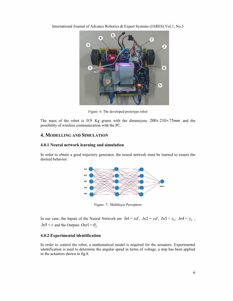
Figure 6: The developed prototype robot
The mass of the robot is 0.9 Kg grams with the dimensions 200 210 75mm and the possibility of wireless communication with the PC.
4. MODELLING AND SIMULATION 4.0.1 Neural network learning and simulation
In order to obtain a good trajectory generator, the neural network must be learned to ensure the desired behavior.
Figure 7: Multilayer Perceptron
In our case, the Inputs of the Neural Network are 1 =In xd , 2 =In yd , 03 =In x , 04 =In y ,
5 =In t and the Outputs 1 = dOut
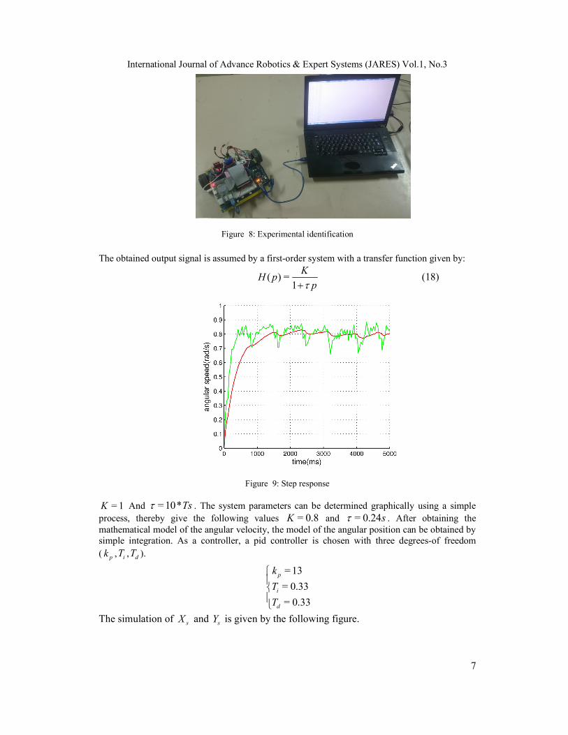
4.0.2 Experimental identification In order to control the robot, a mathematical model is required for the actuators. Experimental identification is used to determine the angular speed in terms of voltage, a step has been applied to the actuators shown in fig.8.
International Journal of Advance Robotics & Expert Systems (JARES) Vol.1, No.3
7
Figure 8: Experimental identification
The obtained output signal is assumed by a first-order system with a transfer function given by:
( ) =1
KH p
p (18)
Figure 9: Step response
= 1K And = 10*Ts . The system parameters can be determined graphically using a simple process, thereby give the following values = 0.8K and = 0.24s . After obtaining the mathematical model of the angular velocity, the model of the angular position can be obtained by simple integration. As a controller, a pid controller is chosen with three degrees-of freedom ( pk , iT , dT ).
= 13
= 0.33
= 0.33
p
i
d
k
T
T
The simulation of sX and sY is given by the following figure.
International Journal of Advance Robotics & Expert Systems (JARES) Vol.1, No.3
8
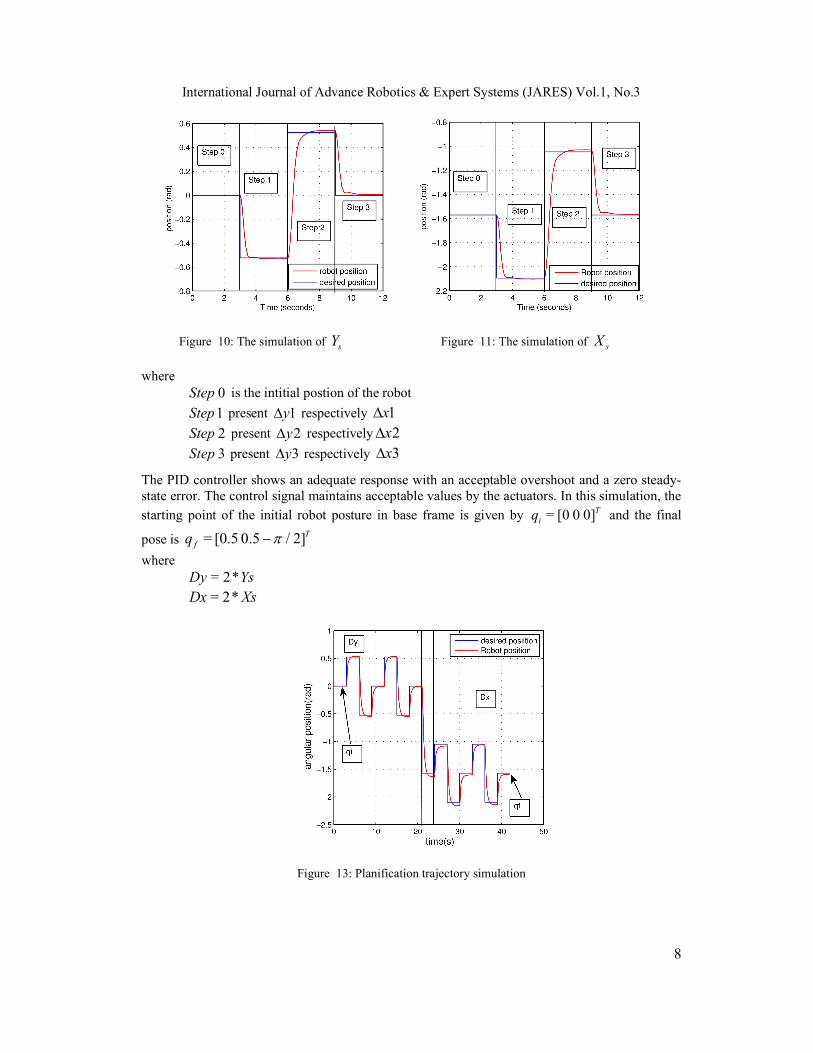
Figure 10: The simulation of sY Figure 11: The simulation of sX
where 0Step is the intitial postion of the robot
1Step present 1y respectively 1x
2Step present 2y respectively 2x
3Step present 3y respectively 3x
The PID controller shows an adequate response with an acceptable overshoot and a zero steady-state error. The control signal maintains acceptable values by the actuators. In this simulation, the
starting point of the initial robot posture in base frame is given by = [0 0 0]Tiq and the final
pose is = [0.5 0.5 / 2]Tfq
where = 2*Dy Ys
= 2*Dx Xs
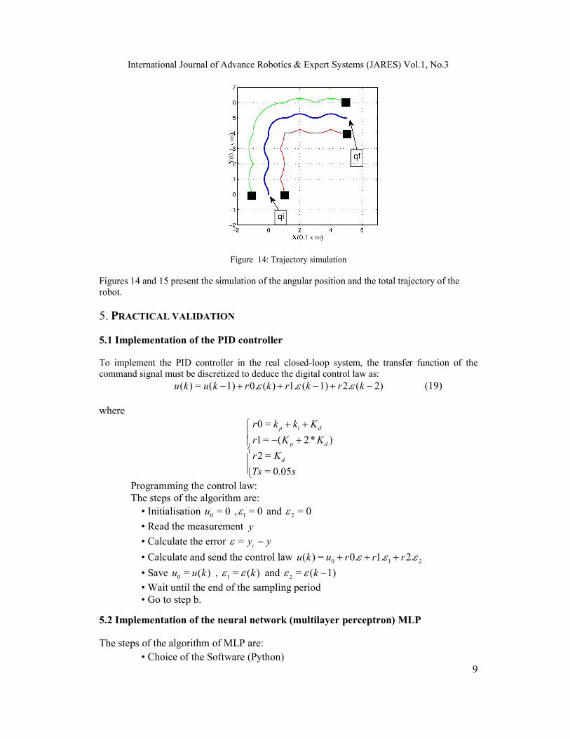
Figure 13: Planification trajectory simulation
International Journal of Advance Robotics & Expert Systems (JARES) Vol.1, No.3
9
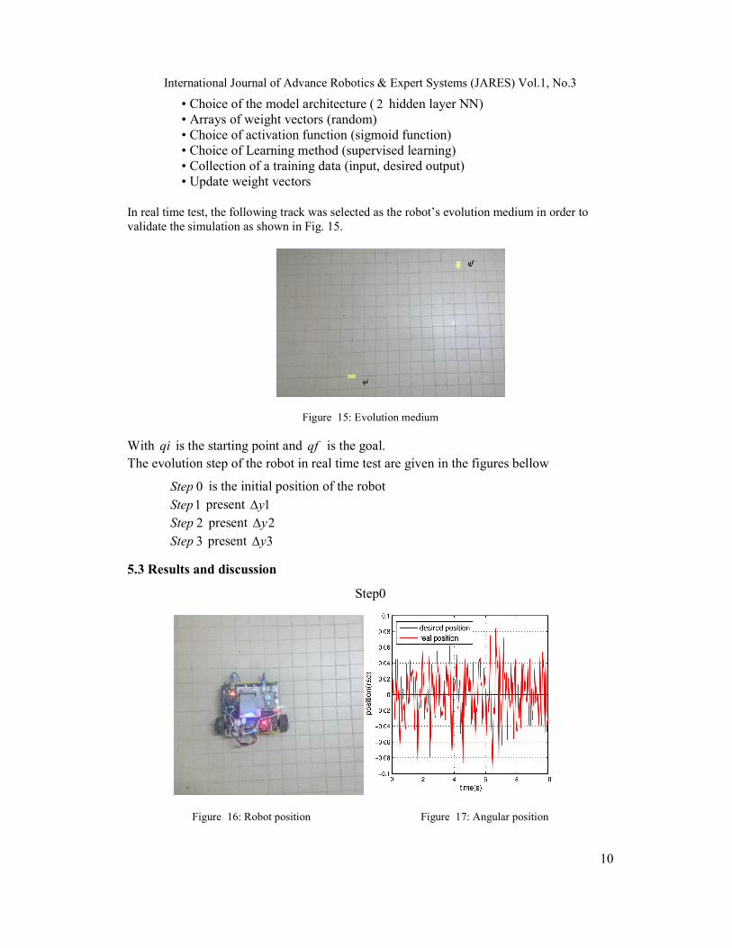
Figure 14: Trajectory simulation
Figures 14 and 15 present the simulation of the angular position and the total trajectory of the robot.
5. PRACTICAL VALIDATION 5.1 Implementation of the PID controller To implement the PID controller in the real closed-loop system, the transfer function of the command signal must be discretized to deduce the digital control law as: ( ) = ( 1) 0. ( ) 1. ( 1) 2. ( 2)u k u k r k r k r k (19) where
0 =
1 = ( 2* )
2 =
= 0.05
p i d
p d
d
r k k K
r K K
r K
Ts s
Programming the control law: The steps of the algorithm are: • Initialisation 0 = 0u , 1 = 0 and 2 = 0
• Read the measurement y
• Calculate the error = cy y
• Calculate and send the control law 0 1 2( ) = 0. 1. 2.u k u r r r
• Save 0 = ( )u u k , 1 = ( )k and 2 = ( 1)k
• Wait until the end of the sampling period • Go to step b.
5.2 Implementation of the neural network (multilayer perceptron) MLP
The steps of the algorithm of MLP are: • Choice of the Software (Python)
International Journal of Advance Robotics & Expert Systems (JARES) Vol.1, No.3
10
• Choice of the model architecture ( 2 hidden layer NN) • Arrays of weight vectors (random) • Choice of activation function (sigmoid function) • Choice of Learning method (supervised learning) • Collection of a training data (input, desired output) • Update weight vectors
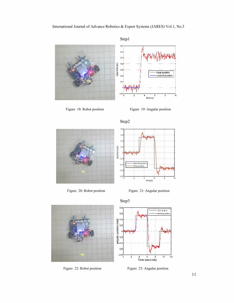
In real time test, the following track was selected as the robot’s evolution medium in order to validate the simulation as shown in Fig. 15.
Figure 15: Evolution medium
With qi is the starting point and qf is the goal. The evolution step of the robot in real time test are given in the figures bellow
0Step is the initial position of the robot 1Step present 1y 2Step present 2y 3Step present 3y
5.3 Results and discussion
Step0
Figure 16: Robot position Figure 17: Angular position
International Journal of Advance Robotics & Expert Systems (JARES) Vol.1, No.3
11
Step1
Figure 18: Robot position Figure 19: Angular position
Step2
Figure 20: Robot position Figure 21: Angular position
Step3
Figure 22: Robot position Figure 23: Angular position
International Journal of Advance Robotics & Expert Systems (JARES) Vol.1, No.3
12
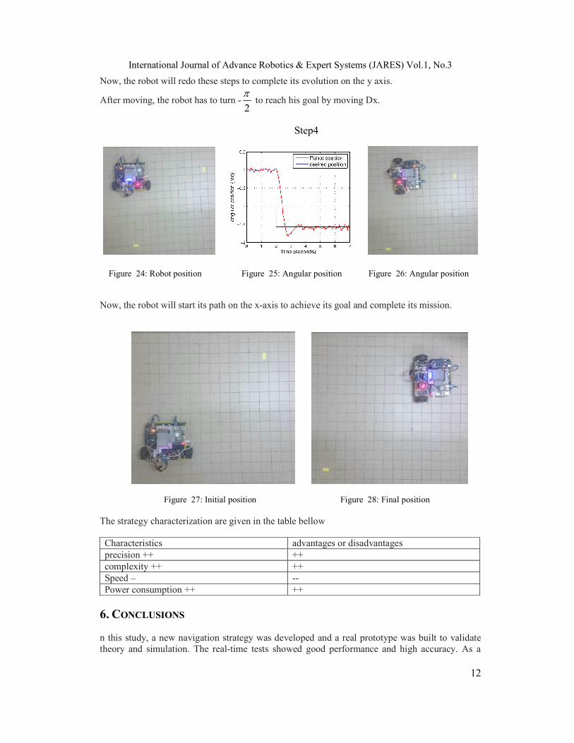
Now, the robot will redo these steps to complete its evolution on the y axis.
After moving, the robot has to turn -2
to reach his goal by moving Dx.
Step4
Figure 24: Robot position Figure 25: Angular position Figure 26: Angular position
Now, the robot will start its path on the x-axis to achieve its goal and complete its mission.
Figure 27: Initial position Figure 28: Final position
The strategy characterization are given in the table bellow
Characteristics advantages or disadvantages precision ++ ++
complexity ++ ++ Speed – -- Power consumption ++ ++
6. CONCLUSIONS n this study, a new navigation strategy was developed and a real prototype was built to validate theory and simulation. The real-time tests showed good performance and high accuracy. As a
International Journal of Advance Robotics & Expert Systems (JARES) Vol.1, No.3
13
perspective, an attention will be focused on the generalization of the strategy for other types of mobile robots.
ACKNOWLEDGEMENTS This work was supported by the Ministry of the Higher Education and Scientific Research in Tunisia. REFERENCES [1] Borenstein, J., Experimental results from internal odometry error correction with the OmniMate
mobile robot journal=IEEE Transactions on Robotics and Automation, In volume=14, number=6, pages=963-969,1998, publisher=IEEE.
[2] C. T. Sauer, H. Brugger, E. P. Hofer, and B. Tibken. Odometry error correction by sensor fusion for
autonomous mobile robot navigation. 3:1654–1658, 2001. [3] A. Martinelli. The odometry error of a mobile robot with a synchronous drive system. IEEE
Transactions on Robotics and Automation, 18(3):399–405, 2002. [4] J. Palacn Roca, J. A. Salse, Ignasi Valgan, and Xavier Clua. Building a mobile robot for a floor-
cleaning operation in domestic environments. IEEE Transactions on Instrumentation and Measurement, 2004, vol. 53,p. 1418-1424, 2004.
[5] Johann Borenstein. The clapper: A dual-drive mobile robot with internal correction of dead-reckoning
errors. pages 3085–3090, 1994. [6] OKAMOTO Kenji. Ultrasonic doppler speed sensor with an offset parabolic reflector. JSAM,
63(2):53–59, 2001. [7] Lin Zhao, Washington Y Ochieng, Mohammed A Quddus, and Robert B Noland. An extended
kalman filter algorithm for integrating gps and low cost dead reckoning system data for vehicle performance and emissions monitoring. The journal of Navigation, 56(02):257–275, 2003.
[8] C.Rocken, R. Anthes, M. Exner, D. Hunt Analysis and validation of gps/met data in the neutral
atmosphere. Journal of Geophysical Research: Atmospheres, 102(D25):29849–29866, 1997. [9] Toshihiro Aono, Kenjiro Fujii, Shintaro Hatsumoto, and Takayuki Kamiya. Mobile Indicators in GIS
and GPS Positioning Accuracy in Cities In Robotics and Automation, 1998. Proceedings. 1998 IEEE International Conference on, volume 4, pages 3443–3448. IEEE, 1998. [10] Artur Janowski, Aleksander Nowak, Marek Przyborski, and Jakub Szulwic. Mobile Indicators in GIS
and GPS Positioning Accuracy in Cities In Rough Sets and Intelligent Systems Paradigms, RSEISP 2014
Authors Radwen Bahri was born in Tunisia. He is currently an Ph.D student in the National Engineering School of Gabes (Tunisia) and he is a member of the Modelling, Analysis and Control of Systems (MACS) laboratory. His current research interests include automatic control, robotics, and sensor design.
.


![OmBURo: A Novel Unicycle Robot with Active ...junjie/publication/OmBURo A Novel...A robot that uses a ball instead of a wheel (a.k.a. Ballbot [1], [19], [20]) can move in any arbitrary](https://img.pdfslide.net/doc/110x75/5fa3c15260725b3c6b7f5676/omburo-a-novel-unicycle-robot-with-active-junjiepublicationomburo-a-novel.jpg)