Embed Size (px)
Citation preview
Fuel 90 (2011) 263–271
Contents lists available at ScienceDirect
Fuel
journal homepage: www.elsevier .com/locate / fuel
A novel power generation system based on moderate conversionof chemical energy of coal and natural gas
Wei Han ⇑, Hongguang Jin 1, Rumou Lin 2
Institute of Engineering Thermophysics, Chinese Academy of Sciences, Beijing 100190, China
a r t i c l e i n f o a b s t r a c t
Article history:Received 4 December 2009Received in revised form 27 May 2010Accepted 9 September 2010Available online 24 September 2010
Keywords:Power generation systemModerate conversionChemical energyNatural gas and coal
0016-2361/$ - see front matter � 2010 Elsevier Ltd. Adoi:10.1016/j.fuel.2010.09.005
⇑ Corresponding author. Tel.: +86 10 82543027; faxE-mail addresses: [email protected] (W. Han)
[email protected] (R. Lin).1 Tel: +86 10 82543032; fax: +86 10 82622854.2 Tel: +86 10 82543028; fax: +86 10 82622854.
This paper proposes a novel power generation system that implements mutually beneficial use of naturalgas and coal. In conventional power plants fossil fuels are usually directly burned with air to convert thechemical energy to thermal energy for power generation. In combustion processes, about 30% of exergy offuels is destructed, and the decrease in the irreversibility of combustion processes has large potential toimprove the performance of power plants. The new system attempts to use chemical exergy of fuelsbefore combustion through coordinated use of coal and natural gas. First approximate 60% of coal is gas-ified in a gasifier with air and steam as oxidant, then, the unconverted residuals (char) and natural gas areutilized synthetically based on the method of char-fired reforming to generate syngas, in which the com-bustion of char will drive the methane/steam-reforming reaction. The fuel gas from the partial gasifica-tion of coal and syngas from char-fired reforming are mixed together and fed into a combined cycle forpower generation. As a result, the overall thermal efficiency of the new system is about 51.5% based onthe current turbine technologies and the net thermal efficiency of coal to electricity of the new systemcan reach near 48.6%. The results obtained here may provide a new way of using coal and natural gasmore efficiently and economically.
� 2010 Elsevier Ltd. All rights reserved.
1. Introduction
Coal and natural gas serve as the primary energy source in thepower industry, and the energy consumption will continue to in-crease in the future. Given the low reserves-to-production ratios,the efficient use of fossil fuels has become an important issue [1].
Coal will play a significant role in the future global energy sys-tem due to extensive coal reserves [2,3]. The coal-fired steam cycleis the most commercial technology for power generation. In theseplants, coal is directly burned in a boiler and generates super-heated steam to drive a steam turbine. Since the steam tempera-ture is lower than 650 �C, a large temperature difference exists inthe boiler, which causes about 40% of the coal’s chemical exergyto be destructed [4]. Several advanced thermal cycles with coalas fuel have been proposed, such as the Externally Fired HumidAir Turbine (EFHAT), the Integrated Gasification Combined Cycle(IGCC), and the Pressurized Fluidized Bed Combustion (PFBC).The EFHAT is an indirectly fired combined cycle [5] with humidair as its working fluid. Although the temperature of air can in-
ll rights reserved.
: +86 10 82622854., [email protected] (H. Jin),
crease obviously comparing with the steam cycle, it has the poten-tial for higher efficiency. However, the higher efficiency dependson the high-temperature of air, and the heat exchanger materialsare currently limited to 1100 K. Gasification of coal has been con-sidered a promising and effective technology. In the IGCC, coal isfirst converted to syngas, which is then burned in a combined cy-cle. Currently, many demonstration plants of the IGCC have begunto operate throughout the world [6]. However, the gasification ofcoal is complex, requiring a gasifier, cleanup unit and air separa-tion unit (ASU) [7,8]. The complex configuration results in an extre-mely high capital cost [9], which limits the large-scale applicationof IGCC. The PFBC also has the potential to reach higher efficiency,especially the second-generation system. In PFBC systems, air canbe used as oxidant directly, and only part of components of coalis converted to syngas. Coal partial gasifier is the key equipmentin PFBC. Currently, coal partial gasification is in pilot plant stage.Experimental results of coal partial gasification in a lab-scale anda pilot-scale air/steam-blown pressurized spout-fluid bed respec-tively were reported in reference papers [10,11]. To obtain highperformance, the solid wastes and SO2 have to be removed effi-ciently from flue gas or fuel gas under high-temperature conditionsbefore being supplied to the gas turbine [12–14].
Natural gas is another commonly used fossil fuel for power gen-eration. Currently, power generation from natural gas depends oncombined cycles. In these cycles, natural gas is directly burned in
Nomenclature
AcronymsIGCC Integrated gasification combined cycleCC Combined cycleA Energy levelEUD Energy utilization diagrame ExergyH Enthalpy
HE Heat exchangerHRSG Heat recovery steam generatorNG Natural gas
Subscriptsed Energy donorea Energy accepter
264 W. Han et al. / Fuel 90 (2011) 263–271
the combustion chamber and the exergy destruction during com-bustion accounts for about half of the total exergy destruction[4]. Researchers have attempted to reduce the exergy destructionby using a chemically recuperated gas turbine (CRGT) [15–19].The cascade utilization of chemical energy of natural gas is dis-closed [20], and the temperature and molar ratio of steam to meth-ane of reforming reaction are the key factors. However, theefficiency of the CRGT is difficult to improve further because theCRGT cycle by itself cannot provide the optimal conditions forthe reforming reaction.
A new method, coal-fired methane/steam-reforming, was pro-posed [21] to produce syngas by the synthetic use of coal and nat-ural gas. In this method, the thermal energy for the reformingreaction is provided by the combustion of coal. Several advancedenergy systems were investigated based on this new method,and these systems showed excellent thermal performance[22,23]. However, the coal-fired methane steam-reforming methodonly focuses on the cascade utilization of chemical energy of natu-ral gas. The efficient use of the chemical energy of coal and that ofnatural gas has not been considered.
The objectives of this paper are (1) to propose a new approachto combine coal partial gasification and natural gas reforming; (2)to integrate a new power generation system based on the new ap-proach; (3) to identify the advantages of the new approach in thepower plant.
2. Novel power generation system with synthetic use of coal andnatural gas
2.1. Conceptual design of the novel power generation system
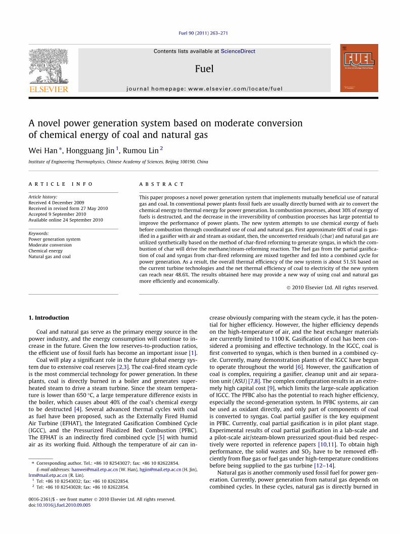
Fig. 1 illustrates the schematic of the novel power generationsystem that uses moderate conversion of coal and natural gasand is based on two fundamental concepts:
Fig. 1. Schematic of the power generation system based on mod
(1) To efficiently use different components of coal based onchemical activities; and
(2) To utilize reasonably the chemical energy of natural gas.
Coal is introduced to a partial gasifier along with air and steamfrom the heat recovery steam generator. In the gasifier part of thecomponents of coal is converted to syngas, which can be evaluatedby the ratio of carbon converted to syngas to the total carbon input.In the full gasification process, the conversion ratio of carbon isusually greater than 95% because higher conversion ratios meanlower energy loss. To implement such high conversion ratios, thegasification process requires pure oxygen as an oxidant and a gas-ifier of a much larger volume to provide a long residence time,which makes the full gasification complex and expensive. By con-trast, partial gasification does not pursue the high conversion ratio;instead, the emphasis is focused on converting the chemically ac-tive components of coal into syngas. The carbon conversion ratiocan be changed from 30% to 70% by controlling the quantity ofsteam and air and the residence time. The volatile matter in coaland active carbon-rich components are quickly converted into syn-gas, and the inactive carbon-rich components and ash are changedinto char [24]. During partial gasification, most of the harmfulconstituents, such as sulfur and alkali metals, enter the syngas. Incontrast to the high-temperature cleanup method used in conven-tional partial gasification, the newly proposed system implementslow-temperature cleanup technology. The high-temperature syn-gas is first cooled down in an HRSG by water and then enters acleanup unit to remove the pollutants.
In a conventional combined cycle, natural gas is burned directlyin the combustor of a gas turbine and large exergy is destructed. Inthe new system, natural gas and steam are first converted to syn-gas in a methane/steam reformer. The reforming process is basedon two independent equilibrium-limited reactions as follows:
CH4 þH2O! 3H2 þ CO DH0298 ¼ 206kJ=mol ðAÞ
COþH2O! CO2 þH2 DH0298 ¼ �41kJ=mol ðBÞ
erate conversion of chemical energy of coal and natural gas.
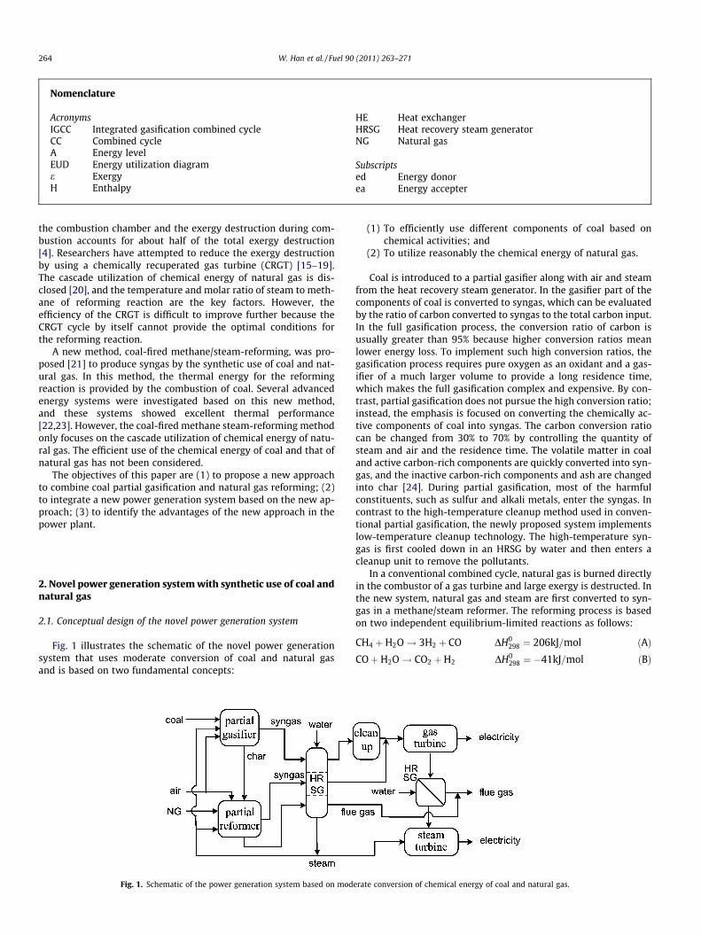
Fig. 2. System configuration of the new power generation system based on moderate conversion of chemical energy of coal and natural gas.
W. Han et al. / Fuel 90 (2011) 263–271 265
Reaction (A) is an endothermic steam-reforming reaction, andthe typical reaction temperature is higher than 900 �C. Reaction(B), often known as the water–gas shift reaction, is a lightly exo-thermic reaction. As a whole, the reforming of methane by steamwill absorb a large amount of high-temperature thermal energy.In the new system, the char from the coal partial gasifier is burnedin the outside reaction tubes of the reformer, and the released ther-mal energy is provided to the reaction. In addition, the concept ofmoderate conversion is implemented in the reforming process.Only a portion of the natural gas is converted to syngas, and thereforming temperature can be decreased from 900 �C to 800 �C.The syngas from the coal and natural gas is mixed and providedto the gas turbine as fuel. The exhaust gas of the gas turbine andthe flue gas of char combustion are also introduced to an HRSGto supply superheated steam to a steam turbine.
2.2. Configuration of the new power plant
Fig. 2 shows the flowchart of the new power plant based onmoderate conversion of the chemical energy of coal and naturalgas. This system is mainly composed of two subsystems: the syn-gas production and heat recovery subsystem and the power gener-ation subsystem. Coal along with air pressed by a compressor, andsteam extracted from the steam turbine enter the partial gasifier,where the chemically active components are converted into syngasand the inactive components are converted into char. In the newsystem, about 60% of the carbon is converted into raw syngas,which consists of ash, hydrogen sulfide, alkali metals, carbon mon-oxide, hydrogen, and carbon dioxide. The high-temperature syngasis first cooled in a heat exchanger (HE1), generating superheatedsteam at the same time. During the cooling process, the alkali met-als coagulate on the surface of the ash, and then the ash and alkali
metals are removed from the syngas through a precipitator. Finally,the hydrogen sulfide is separated by an FGD unit, resulting in cleansyngas. Several technologies, such as Selexol solvent absorption,are commercially available to capture H2S [25].
The residual char from the gasifier is transmitted to the char-fired methane/steam-reformer. The char is burned with preheatedair outside the reaction tubes, and the released thermal energy isabsorbed by the reforming reaction occurring inside the reactiontubes. The surplus heat of flue gas is used to generate steam in heatexchangers (HE2 and HE3) and to preheat the combustion air(HE4). Since most of the sulfur derived from coal has been trans-formed into H2S in syngas, the remnant sulfur can be removedby adding limestone during the char combustion. The syngas fromthe partial reformer is mixed with the clean syngas from the partialgasifier, and the mixture is sent to a combined cycle as fuel. Thenew system adopts a two-pressure reheated steam turbine. Thesteam used in the reforming and partial gasification process is ex-tracted from the steam turbine.
2.3. Brief description of reference systems
The energy system proposed in this paper has multiple inputs offossil fuels: Therefore, we estimated the performance of the newpower plant based on a comparison to the reference systems,which included the IGCC based on coal and the combined cyclebased on natural gas. The IGCC is assumed to be an integration ofTexaco’s gasification process, gas cleanup, and heat recovery sys-tem with a gas turbine generator, a heat recovery steam generator(HRSG), and a steam turbine generator [26]. The combined cycleconsists of a gas turbine, a heat recovery steam generator, and asteam turbine. The gas turbine inlet temperature and pressureratio are 1300 �C and 15, respectively. The steam turbine inlet
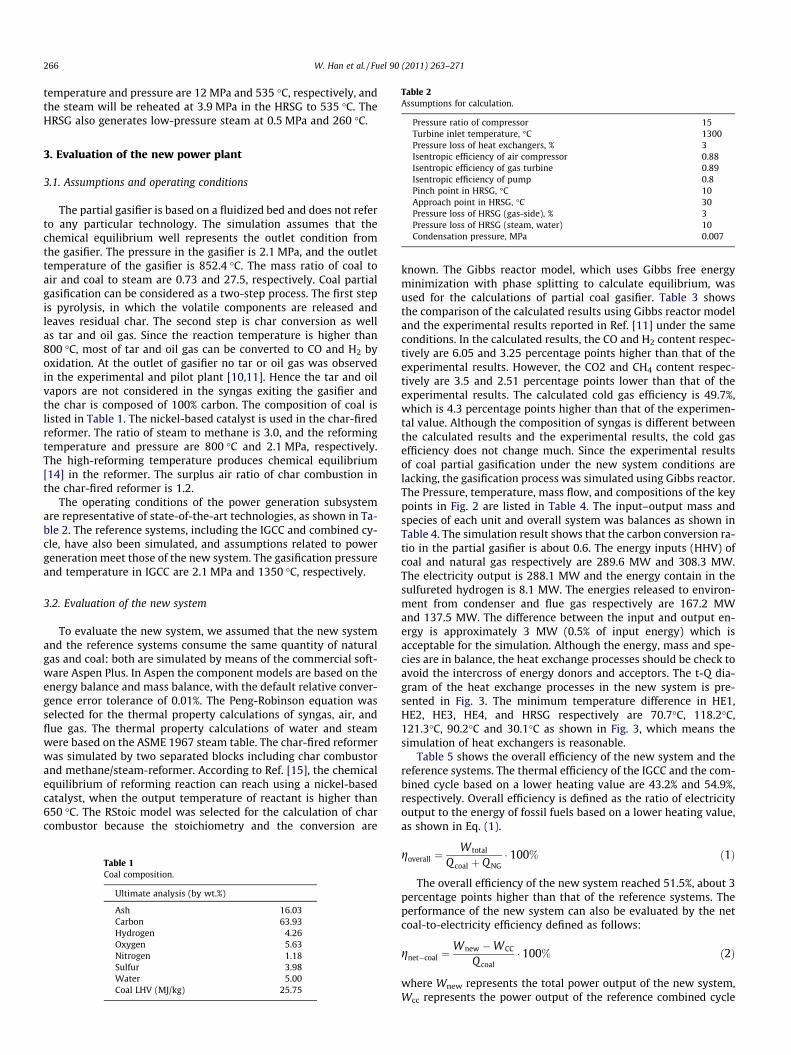
Table 2Assumptions for calculation.
Pressure ratio of compressor 15
266 W. Han et al. / Fuel 90 (2011) 263–271
temperature and pressure are 12 MPa and 535 �C, respectively, andthe steam will be reheated at 3.9 MPa in the HRSG to 535 �C. TheHRSG also generates low-pressure steam at 0.5 MPa and 260 �C.
Turbine inlet temperature, �C 1300Pressure loss of heat exchangers, % 3Isentropic efficiency of air compressor 0.88Isentropic efficiency of gas turbine 0.89Isentropic efficiency of pump 0.8Pinch point in HRSG, �C 10Approach point in HRSG, �C 30Pressure loss of HRSG (gas-side), % 3Pressure loss of HRSG (steam, water) 10Condensation pressure, MPa 0.007
3. Evaluation of the new power plant
3.1. Assumptions and operating conditions
The partial gasifier is based on a fluidized bed and does not referto any particular technology. The simulation assumes that thechemical equilibrium well represents the outlet condition fromthe gasifier. The pressure in the gasifier is 2.1 MPa, and the outlettemperature of the gasifier is 852.4 �C. The mass ratio of coal toair and coal to steam are 0.73 and 27.5, respectively. Coal partialgasification can be considered as a two-step process. The first stepis pyrolysis, in which the volatile components are released andleaves residual char. The second step is char conversion as wellas tar and oil gas. Since the reaction temperature is higher than800 �C, most of tar and oil gas can be converted to CO and H2 byoxidation. At the outlet of gasifier no tar or oil gas was observedin the experimental and pilot plant [10,11]. Hence the tar and oilvapors are not considered in the syngas exiting the gasifier andthe char is composed of 100% carbon. The composition of coal islisted in Table 1. The nickel-based catalyst is used in the char-firedreformer. The ratio of steam to methane is 3.0, and the reformingtemperature and pressure are 800 �C and 2.1 MPa, respectively.The high-reforming temperature produces chemical equilibrium[14] in the reformer. The surplus air ratio of char combustion inthe char-fired reformer is 1.2.
The operating conditions of the power generation subsystemare representative of state-of-the-art technologies, as shown in Ta-ble 2. The reference systems, including the IGCC and combined cy-cle, have also been simulated, and assumptions related to powergeneration meet those of the new system. The gasification pressureand temperature in IGCC are 2.1 MPa and 1350 �C, respectively.
3.2. Evaluation of the new system
To evaluate the new system, we assumed that the new systemand the reference systems consume the same quantity of naturalgas and coal: both are simulated by means of the commercial soft-ware Aspen Plus. In Aspen the component models are based on theenergy balance and mass balance, with the default relative conver-gence error tolerance of 0.01%. The Peng-Robinson equation wasselected for the thermal property calculations of syngas, air, andflue gas. The thermal property calculations of water and steamwere based on the ASME 1967 steam table. The char-fired reformerwas simulated by two separated blocks including char combustorand methane/steam-reformer. According to Ref. [15], the chemicalequilibrium of reforming reaction can reach using a nickel-basedcatalyst, when the output temperature of reactant is higher than650 �C. The RStoic model was selected for the calculation of charcombustor because the stoichiometry and the conversion are
Table 1Coal composition.
Ultimate analysis (by wt.%)
Ash 16.03Carbon 63.93Hydrogen 4.26Oxygen 5.63Nitrogen 1.18Sulfur 3.98Water 5.00Coal LHV (MJ/kg) 25.75
known. The Gibbs reactor model, which uses Gibbs free energyminimization with phase splitting to calculate equilibrium, wasused for the calculations of partial coal gasifier. Table 3 showsthe comparison of the calculated results using Gibbs reactor modeland the experimental results reported in Ref. [11] under the sameconditions. In the calculated results, the CO and H2 content respec-tively are 6.05 and 3.25 percentage points higher than that of theexperimental results. However, the CO2 and CH4 content respec-tively are 3.5 and 2.51 percentage points lower than that of theexperimental results. The calculated cold gas efficiency is 49.7%,which is 4.3 percentage points higher than that of the experimen-tal value. Although the composition of syngas is different betweenthe calculated results and the experimental results, the cold gasefficiency does not change much. Since the experimental resultsof coal partial gasification under the new system conditions arelacking, the gasification process was simulated using Gibbs reactor.The Pressure, temperature, mass flow, and compositions of the keypoints in Fig. 2 are listed in Table 4. The input–output mass andspecies of each unit and overall system was balances as shown inTable 4. The simulation result shows that the carbon conversion ra-tio in the partial gasifier is about 0.6. The energy inputs (HHV) ofcoal and natural gas respectively are 289.6 MW and 308.3 MW.The electricity output is 288.1 MW and the energy contain in thesulfureted hydrogen is 8.1 MW. The energies released to environ-ment from condenser and flue gas respectively are 167.2 MWand 137.5 MW. The difference between the input and output en-ergy is approximately 3 MW (0.5% of input energy) which isacceptable for the simulation. Although the energy, mass and spe-cies are in balance, the heat exchange processes should be check toavoid the intercross of energy donors and acceptors. The t-Q dia-gram of the heat exchange processes in the new system is pre-sented in Fig. 3. The minimum temperature difference in HE1,HE2, HE3, HE4, and HRSG respectively are 70.7�C, 118.2�C,121.3�C, 90.2�C and 30.1�C as shown in Fig. 3, which means thesimulation of heat exchangers is reasonable.
Table 5 shows the overall efficiency of the new system and thereference systems. The thermal efficiency of the IGCC and the com-bined cycle based on a lower heating value are 43.2% and 54.9%,respectively. Overall efficiency is defined as the ratio of electricityoutput to the energy of fossil fuels based on a lower heating value,as shown in Eq. (1).
goverall ¼W total
Q coal þ Q NG� 100% ð1Þ
The overall efficiency of the new system reached 51.5%, about 3percentage points higher than that of the reference systems. Theperformance of the new system can also be evaluated by the netcoal-to-electricity efficiency defined as follows:
gnet�coal ¼Wnew �WCC
Q coal� 100% ð2Þ
where Wnew represents the total power output of the new system,Wcc represents the power output of the reference combined cycle
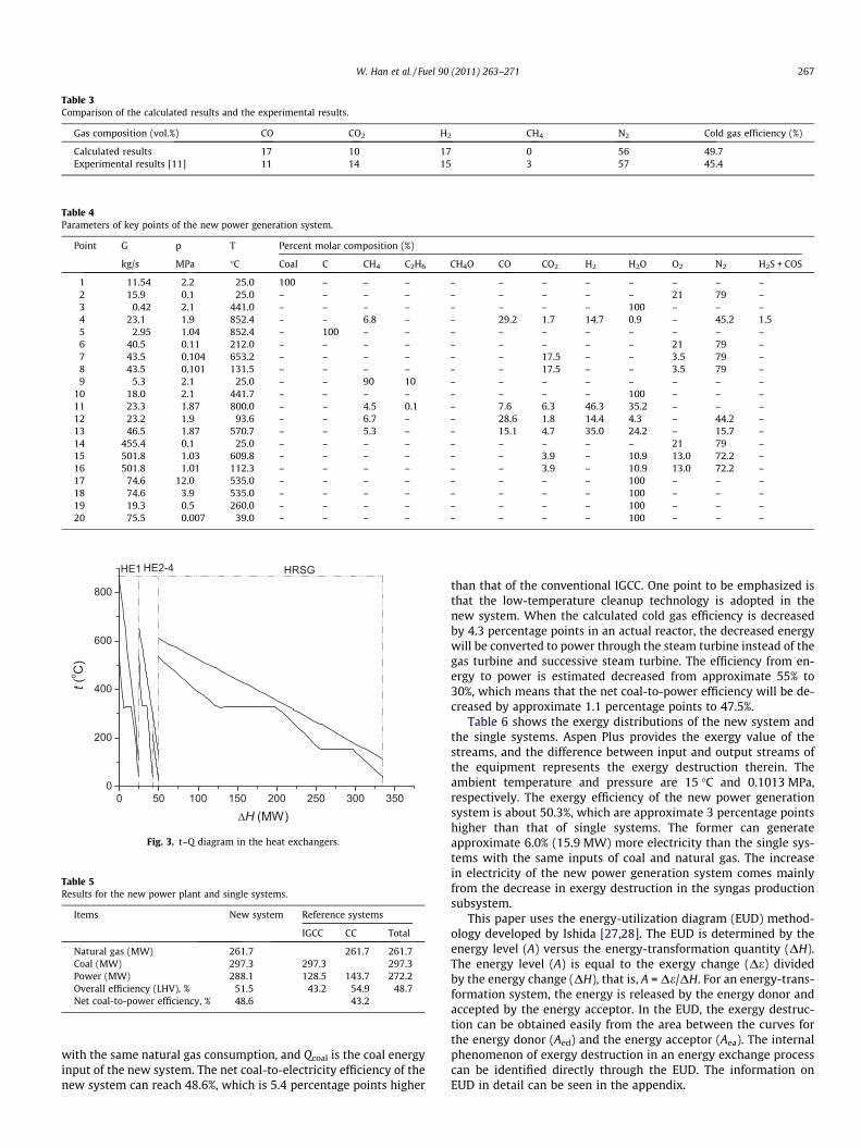
Table 3Comparison of the calculated results and the experimental results.
Gas composition (vol.%) CO CO2 H2 CH4 N2 Cold gas efficiency (%)
Calculated results 17 10 17 0 56 49.7Experimental results [11] 11 14 15 3 57 45.4
Table 4Parameters of key points of the new power generation system.
Point G p T Percent molar composition (%)
kg/s MPa �C Coal C CH4 C2H6 CH4O CO CO2 H2 H2O O2 N2 H2S + COS
1 11.54 2.2 25.0 100 – – – – – – – – – – –2 15.9 0.1 25.0 – – – – – – – – – 21 79 –3 0.42 2.1 441.0 – – – – – – – – 100 – – –4 23.1 1.9 852.4 – – 6.8 – – 29.2 1.7 14.7 0.9 – 45.2 1.55 2.95 1.04 852.4 – 100 – – – – – – – – – –6 40.5 0.11 212.0 – – – – – – – – – 21 79 –7 43.5 0.104 653.2 – – – – – – 17.5 – – 3.5 79 –8 43.5 0.101 131.5 – – – – – – 17.5 – – 3.5 79 –9 5.3 2.1 25.0 – – 90 10 – – – – – – – –
10 18.0 2.1 441.7 – – – – – – – – 100 – – –11 23.3 1.87 800.0 – – 4.5 0.1 – 7.6 6.3 46.3 35.2 – – –12 23.2 1.9 93.6 – – 6.7 – – 28.6 1.8 14.4 4.3 – 44.2 –13 46.5 1.87 570.7 – – 5.3 – – 15.1 4.7 35.0 24.2 – 15.7 –14 455.4 0.1 25.0 – – – – – – – – – 21 79 –15 501.8 1.03 609.8 – – – – – – 3.9 – 10.9 13.0 72.2 –16 501.8 1.01 112.3 – – – – – – 3.9 – 10.9 13.0 72.2 –17 74.6 12.0 535.0 – – – – – – – – 100 – – –18 74.6 3.9 535.0 – – – – – – – – 100 – – –19 19.3 0.5 260.0 – – – – – – – – 100 – – –20 75.5 0.007 39.0 – – – – – – – – 100 – – –
Fig. 3. t–Q diagram in the heat exchangers.
Table 5Results for the new power plant and single systems.
Items New system Reference systems
IGCC CC Total
Natural gas (MW) 261.7 261.7 261.7Coal (MW) 297.3 297.3 297.3Power (MW) 288.1 128.5 143.7 272.2Overall efficiency (LHV), % 51.5 43.2 54.9 48.7Net coal-to-power efficiency, % 48.6 43.2
W. Han et al. / Fuel 90 (2011) 263–271 267
with the same natural gas consumption, and Qcoal is the coal energyinput of the new system. The net coal-to-electricity efficiency of thenew system can reach 48.6%, which is 5.4 percentage points higher
than that of the conventional IGCC. One point to be emphasized isthat the low-temperature cleanup technology is adopted in thenew system. When the calculated cold gas efficiency is decreasedby 4.3 percentage points in an actual reactor, the decreased energywill be converted to power through the steam turbine instead of thegas turbine and successive steam turbine. The efficiency from en-ergy to power is estimated decreased from approximate 55% to30%, which means that the net coal-to-power efficiency will be de-creased by approximate 1.1 percentage points to 47.5%.
Table 6 shows the exergy distributions of the new system andthe single systems. Aspen Plus provides the exergy value of thestreams, and the difference between input and output streams ofthe equipment represents the exergy destruction therein. Theambient temperature and pressure are 15 �C and 0.1013 MPa,respectively. The exergy efficiency of the new power generationsystem is about 50.3%, which are approximate 3 percentage pointshigher than that of single systems. The former can generateapproximate 6.0% (15.9 MW) more electricity than the single sys-tems with the same inputs of coal and natural gas. The increasein electricity of the new power generation system comes mainlyfrom the decrease in exergy destruction in the syngas productionsubsystem.
This paper uses the energy-utilization diagram (EUD) method-ology developed by Ishida [27,28]. The EUD is determined by theenergy level (A) versus the energy-transformation quantity (DH).The energy level (A) is equal to the exergy change (De) dividedby the energy change (DH), that is, A = De/DH. For an energy-trans-formation system, the energy is released by the energy donor andaccepted by the energy acceptor. In the EUD, the exergy destruc-tion can be obtained easily from the area between the curves forthe energy donor (Aed) and the energy acceptor (Aea). The internalphenomenon of exergy destruction in an energy exchange processcan be identified directly through the EUD. The information onEUD in detail can be seen in the appendix.
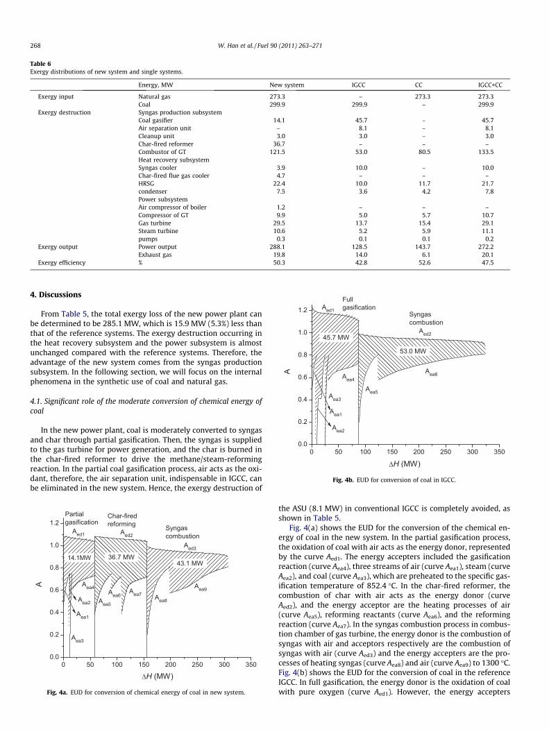
Table 6Exergy distributions of new system and single systems.
Energy, MW New system IGCC CC IGCC+CC
Exergy input Natural gas 273.3 – 273.3 273.3Coal 299.9 299.9 – 299.9
Exergy destruction Syngas production subsystemCoal gasifier 14.1 45.7 – 45.7Air separation unit – 8.1 – 8.1Cleanup unit 3.0 3.0 – 3.0Char-fired reformer 36.7 – – –Combustor of GT 121.5 53.0 80.5 133.5Heat recovery subsystemSyngas cooler 3.9 10.0 – 10.0Char-fired flue gas cooler 4.7 – – –HRSG 22.4 10.0 11.7 21.7condenser 7.5 3.6 4.2 7.8Power subsystemAir compressor of boiler 1.2 – – –Compressor of GT 9.9 5.0 5.7 10.7Gas turbine 29.5 13.7 15.4 29.1Steam turbine 10.6 5.2 5.9 11.1pumps 0.3 0.1 0.1 0.2
Exergy output Power output 288.1 128.5 143.7 272.2Exhaust gas 19.8 14.0 6.1 20.1
Exergy efficiency % 50.3 42.8 52.6 47.5
Fig. 4b. EUD for conversion of coal in IGCC.
268 W. Han et al. / Fuel 90 (2011) 263–271
4. Discussions
From Table 5, the total exergy loss of the new power plant canbe determined to be 285.1 MW, which is 15.9 MW (5.3%) less thanthat of the reference systems. The exergy destruction occurring inthe heat recovery subsystem and the power subsystem is almostunchanged compared with the reference systems. Therefore, theadvantage of the new system comes from the syngas productionsubsystem. In the following section, we will focus on the internalphenomena in the synthetic use of coal and natural gas.
4.1. Significant role of the moderate conversion of chemical energy ofcoal
In the new power plant, coal is moderately converted to syngasand char through partial gasification. Then, the syngas is suppliedto the gas turbine for power generation, and the char is burned inthe char-fired reformer to drive the methane/steam-reformingreaction. In the partial coal gasification process, air acts as the oxi-dant, therefore, the air separation unit, indispensable in IGCC, canbe eliminated in the new system. Hence, the exergy destruction of
Fig. 4a. EUD for conversion of chemical energy of coal in new system.
the ASU (8.1 MW) in conventional IGCC is completely avoided, asshown in Table 5.
Fig. 4(a) shows the EUD for the conversion of the chemical en-ergy of coal in the new system. In the partial gasification process,the oxidation of coal with air acts as the energy donor, representedby the curve Aed1. The energy accepters included the gasificationreaction (curve Aea4), three streams of air (curve Aea1), steam (curveAea2), and coal (curve Aea3), which are preheated to the specific gas-ification temperature of 852.4 �C. In the char-fired reformer, thecombustion of char with air acts as the energy donor (curveAed2), and the energy acceptor are the heating processes of air(curve Aea5), reforming reactants (curve Aea6), and the reformingreaction (curve Aea7). In the syngas combustion process in combus-tion chamber of gas turbine, the energy donor is the combustion ofsyngas with air and acceptors respectively are the combustion ofsyngas with air (curve Aed3) and the energy accepters are the pro-cesses of heating syngas (curve Aea8) and air (curve Aea9) to 1300 �C.Fig. 4(b) shows the EUD for the conversion of coal in the referenceIGCC. In full gasification, the energy donor is the oxidation of coalwith pure oxygen (curve Aed1). However, the energy accepters
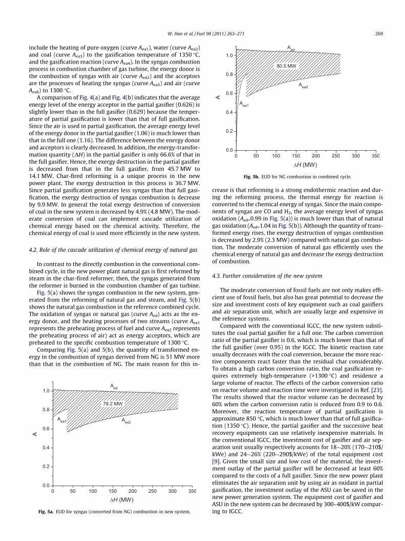
Fig. 5b. EUD for NG combustion in combined cycle.
W. Han et al. / Fuel 90 (2011) 263–271 269
include the heating of pure oxygen (curve Aea1), water (curve Aea2)and coal (curve Aea3) to the gasification temperature of 1350 �C,and the gasification reaction (curve Aea4). In the syngas combustionprocess in combustion chamber of gas turbine, the energy donor isthe combustion of syngas with air (curve Aed2) and the acceptorsare the processes of heating the syngas (curve Aea5) and air (curveAea6) to 1300 �C.
A comparison of Fig. 4(a) and Fig. 4(b) indicates that the averageenergy level of the energy acceptor in the partial gasifier (0.626) isslightly lower than in the full gasifier (0.629) because the temper-ature of partial gasification is lower than that of full gasification.Since the air is used in partial gasification, the average energy levelof the energy donor in the partial gasifier (1.06) is much lower thanthat in the full one (1.16). The difference between the energy donorand acceptors is clearly decreased. In addition, the energy-transfor-mation quantity (DH) in the partial gasifier is only 66.6% of that inthe full gasifier. Hence, the exergy destruction in the partial gasifieris decreased from that in the full gasifier, from 45.7 MW to14.1 MW. Char-fired reforming is a unique process in the newpower plant. The exergy destruction in this process is 36.7 MW.Since partial gasification generates less syngas than that full gasi-fication, the exergy destruction of syngas combustion is decreaseby 9.9 MW. In general the total exergy destruction of conversionof coal in the new system is decreased by 4.9% (4.8 MW). The mod-erate conversion of coal can implement cascade utilization ofchemical energy based on the chemical activity. Therefore, thechemical energy of coal is used more efficiently in the new system.
4.2. Role of the cascade utilization of chemical energy of natural gas
In contrast to the directly combustion in the conventional com-bined cycle, in the new power plant natural gas is first reformed bysteam in the char-fired reformer, then, the syngas generated fromthe reformer is burned in the combustion chamber of gas turbine.
Fig. 5(a) shows the syngas combustion in the new system, gen-erated from the reforming of natural gas and steam, and Fig. 5(b)shows the natural gas combustion in the reference combined cycle.The oxidation of syngas or natural gas (curve Aed) acts as the en-ergy donor, and the heating processes of two streams (curve Aea1
represents the preheating process of fuel and curve Aea2 representsthe preheating process of air) act as energy acceptors, which arepreheated to the specific combustion temperature of 1300 �C.
Comparing Fig. 5(a) and 5(b), the quantity of transformed en-ergy in the combustion of syngas derived from NG is 51 MW morethan that in the combustion of NG. The main reason for this in-
Fig. 5a. EUD for syngas (converted from NG) combustion in new system.
crease is that reforming is a strong endothermic reaction and dur-ing the reforming process, the thermal energy for reaction isconverted to the chemical energy of syngas. Since the main compo-nents of syngas are CO and H2, the average energy level of syngasoxidation (Aed=0.99 in Fig. 5(a)) is much lower than that of naturalgas oxidation (Aed=1.04 in Fig. 5(b)). Although the quantity of trans-formed energy rises, the exergy destruction of syngas combustionis decreased by 2.9% (2.3 MW) compared with natural gas combus-tion. The moderate conversion of natural gas efficiently uses thechemical energy of natural gas and decrease the exergy destructionof combustion.
4.3. Further consideration of the new system
The moderate conversion of fossil fuels are not only makes effi-cient use of fossil fuels, but also has great potential to decrease thesize and investment costs of key equipment such as coal gasifiersand air separation unit, which are usually large and expensive inthe reference systems.
Compared with the conventional IGCC, the new system substi-tutes the coal partial gasifier for a full one. The carbon conversionratio of the partial gasifier is 0.6, which is much lower than that ofthe full gasifier (over 0.95) in the IGCC. The kinetic reaction rateusually decreases with the coal conversion, because the more reac-tive components react faster than the residual char considerably.To obtain a high carbon conversion ratio, the coal gasification re-quires extremely high-temperature (>1300 �C) and residence alarge volume of reactor. The effects of the carbon conversion ratioon reactor volume and reaction time were investigated in Ref. [23].The results showed that the reactor volume can be decreased by60% when the carbon conversion ratio is reduced from 0.9 to 0.6.Moreover, the reaction temperature of partial gasification isapproximate 850 �C, which is much lower than that of full gasifica-tion (1350 �C). Hence, the partial gasifier and the successive heatrecovery equipments can use relatively inexpensive materials. Inthe conventional IGCC, the investment cost of gasifier and air sep-aration unit usually respectively accounts for 18�20% (170�210$/kWe) and 24�26% (220�290$/kWe) of the total equipment cost[9]. Given the small size and low cost of the material, the invest-ment outlay of the partial gasifier will be decreased at least 60%compared to the costs of a full gasifier. Since the new power planteliminates the air separation unit by using air as oxidant in partialgasification, the investment outlay of the ASU can be saved in thenew power generation system. The equipment cost of gasifier andASU in the new system can be decreased by 300–400$/kW compar-ing to IGCC.
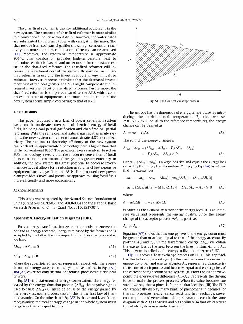
Fig. A1. EUD for heat exchange process.
270 W. Han et al. / Fuel 90 (2011) 263–271
The char-fired reformer is the key additional equipment in thenew system. The structure of char-fired reformer is more similarto a conventional boiler without drum; however, the water tubesare substituted by reformer tubes with catalyst in the inner. Thechar residue from coal partial gasifier shows high combustion reac-tivity and more than 99% combustion efficiency can be achieved[11]. Moreover, the reforming temperature is approximate800 �C, char combustion provides high-temperature heat toreforming reaction is feasible and no serious technical obstacle ex-ists in the char-fired reformer. The char-fired reformer will in-crease the investment cost of the system. By now no such char-fired reformer in use and the investment cost is very difficult toestimate. However, it seems optimistic that the decreased invest-ment cost of the coal gasifier and ASU might compensate the in-creased investment cost of char-fired reformer. Furthermore, thechar-fired reformer is simple compared to the ASU, which com-prises a number of equipments. The control and operation of thenew system seems simple comparing to that of IGCC.
5. Conclusions
This paper proposes a new kind of power generation systembased on the moderate conversion of chemical energy of fossilfuels, including coal partial gasification and char-fired NG partialreforming. With the same coal and natural gas input as single sys-tems, the new system can generate approximate 5.8% more elec-tricity. The net coal-to-electricity efficiency of the new systemcan reach 48.6%, approximate 5 percentage points higher than thatof the conventional IGCC. The graphical exergy analysis based onEUD methodology reveals that the moderate conversion of fossilfuels is the main contributor of the system’s greater efficiency. Inaddition, the new system has great potential to decrease invest-ment costs, as it allows for a reduction in volume of key expensiveequipment such as gasifiers and ASUs. The proposed new powerplant provides a novel and promising approach to using fossil fuelsmore efficiently and more economically.
Acknowledgments
This study was supported by the Natural Science Foundation ofChina (Grant Nos. 50706051 and 50836005) and the National BasicResearch Program of China (Grant No. 2010CB227301).
Appendix A. Energy-Utilization Diagrams (EUDs)
For an energy-transformation system, there exist an energy do-nor and an energy acceptor. Energy is released by the former and isaccepted by the latter. For an energy donor and an energy acceptor,we have
DHed þ DHea ¼ 0 ðA1Þ
DSed þ DSea P 0 ðA2Þ
where the subscripts ed and ea represent, respectively, the energydonor and energy acceptor in the system. DH and DS in Eqs. (A1)and (A2) cover not only thermal or chemical processes but also heator work.
Eq. (A1) is a statement of energy conservation: the energy re-leased by the energy-donation process (DHed, the negative sign isused because DHed < 0) must be equal to the energy gained bythe energy-accepting process (DHea); this is the first law of ther-modynamics. On the other hand, Eq. (A2) is the second law of ther-modynamics; the total entropy change in the whole system mustbe greater than of equal to zero.
The entropy has the dimension of energy/temperature. By intro-ducing the environmental temperature T0 (i.e. we set298.15 K = 25 �C equal to the reference temperature), the exergychange can be defined as
De ¼ DH � T0DS: ðA3Þ
The sum of the exergy changes is
Deed þ Deea ¼ ðDHed þ DHeaÞ � T0ðDSed � DSeaÞ¼ �T0ðDSed þ DSeaÞ 6 0 ðA4Þ
Hence, �(Deed + Deea) is always positive and equals the exergy losscaused by the energy transformation. Mutiplying Eq. (A4) by �1, wefind the exergy loss
�Dei ¼ �Deed � Deea ¼ DHea½�ðDeed=DHeaÞ � ðDeea=DHeaÞ�
¼ DHea½ðDeed=DHedÞ � ðDeea=DHeaÞ� ¼ DHeaðAed � AeaÞP 0 ðA5Þ
where
A ¼ De=DH ¼ 1� T0ðDS=DHÞ ðA6Þ
is called as the availability factor or the energy level. It is an inten-sive value and represents the energy quality. Since the energychange of the acceptor process DHea is positive,
Aed P Aea: ðA7Þ
Equation (A7) shows that the energy level of the energy donor mustbe greater than or at least equal to that of the energy acceptor. Byplotting Aed and Aea vs the transformed energy DHea, we obtainthe exergy loss as the area between the lines limiting Aed and Aea.This diagram is called as the energy-utilization diagram (EUD).
Fig. A1 shows a heat exchange process on EUD. This approachhas the following advantages: (i) the area between the curves forenergy donor Aed and energy acceptor Aea represents a characteris-tic feature of each process and becomes equal to the exergy loss ofthe corresponding section of the system. (ii) From the kinetic view-point, the energy-level difference (Aed–Aea) represents the drivingforce to make the process proceed. When its value becomes toosmall, we say that a pinch is found at that location. (iii) The EUDcan graphically display many kinds of phenomena in chemical orthermal processes (e.g., chemical reactions, heat exchange, powerconsumption and generation, mixing, separation, etc.) in the samediagram with DH as abscissa and A as ordinate so that we can treatthe whole system in a unified manner.
W. Han et al. / Fuel 90 (2011) 263–271 271
References
[1] BP group. BP Statistical Review of World Energy 2008. Report, BP Press Centre,London; 2008.
[2] Cai R, Lin R, Xiao Y, Xu D. Coal-fired combined cycle power generationtechnology with high efficiency, low pollution, and low water consumption,”UNESCO, Senior Conference of Cleaning Coal-Fired Technology, Beijing, China;1993.
[3] Longwell JP, Rubin ES, Wilson J. Coal: Energy for the Future. Prog EnergyCombust Sci 1995;21:269–360.
[4] Jin H, Ishida M, Kobayashi M, Numokawa M. Exergy evaluation of two currentadvanced power plants: supercritical steam turbine and combined cycle. ASMETrans. J. Eng Gas Turbine and Power 1997;119:250–6.
[5] Jin H, Zhao H, Liu Z, Cai R. A novel EFHAT system and exergy analysis withenergy utilization diagram. Energy—Int J 2004; 29: 1983–91.
[6] U. S. Department of Energy and the Gasification Technologies Council.Gasification-worldwide use and acceptance. Topic Rep., USDOE, Washington,D.C, 2000.
[7] Campbell P, McMullan J, Williams B. Concept for a competitive coal firedintegrated gasification combined cycle power plant. Fuel 2000;79:1031–40.
[8] Minchener A. Coal gasification for advanced power generation. Fuel2005;84:2222–35.
[9] Cost and performance baseline for fossil energy plants. DOE/NETL-2007/1281.[10] Xiao R, Zhang M, Jin B, et al. High-temperature air/steam-blown gasification of
coal in a pressurized spout-fluid bed. Energy Fuels 2006;20:715–20.[11] Xiao R, Zhang M, Jin B, et al. Air blown partial gasification of coal in a pilot
plant pressurized spout-fluid bed reactor. Fuel 2007;86:1631–40.[12] Xu Y, Jin H, Lin R, Han W. System study on partial gasification combined cycle
with CO2 recovery. ASME Trans. J. Eng Gas Turbine and Power 2008;130.051801-1.
[13] Lozza G, Chiesa P, De Vita L. Combined-cycle power stations using ‘‘Clean-coaltechnologies”: Thermodynamic analysis of full gasification versus fluidizedbed combustion with partial gasification. ASME Trans. J. Eng Gas Turbine andPower 1996;118:737–48.
[14] Foster Wheeler Development Corporation. Development of pressurizedcirculation fluidized bed partial gasification module (PGM),” Department ofEnergy, Contract No. DE – FC26 – 00NT40972; 2003.
[15] Kesser KF, Hoffman MA, Baughn JW. Analysis of a basic chemically recuperatedgas turbine power plant. ASME Trans. J. Eng Gas Turbine and Power1994;116:277–84.
[16] Han W, Jin H, Zhang N, Zhang X. Cascade utilization of chemical energy ofnatural gas in an improved CRGT cycle. Energy-The Int J 2007;32:306–13.
[17] Abdallah H, Facchini B, Danes F, Ruyck J. Exergy optimization of intercooledreheat chemically recuperated gas turbine. Energy Convers Manage1999;40:1679–86.
[18] Nakagaki T, Ogawa T, Hirata H, Kawamoto K, Ohashi Y, Tanaka K. Developmentof Chemically Recuperated Micro Gas Turbine. ASME Trans. J. Eng Gas Turbineand Power 2003;125:391–7.
[19] Verkhivker G, Kravchenko V. The use of chemical recuperation of heat in apower plant. Energy 2004;29:379–88.
[20] Han W, Jin H, Lin R. A new approach of cascade utilization of the chemicalenergy of fuel. Prog. Nat. Sci. 2006;16:518–23.
[21] Han W, Jin H, Xu W. A novel combined cycle with synthetic utilization of coaland natural gas. Energy–The Int. J 2007;32:1334–42.
[22] Jin H, Han W, Gao L. Multi-functional energy system (MES) with multi fossilfuels and multi products. ASME Trans. J. Eng Gas Turbine and Power2007;129:331–7.
[23] Jin H, Han W, Gao L. A novel multifunctional energy system (MES) for CO2
removal with zero energy penalty. ASME Trans. J. Eng Gas Turbine and Power2008;130:021401.
[24] Tang Z, Wang Y. Efficient and environment friendly use of coal. Fuel ProcessTechnol 2000;62:137–41.
[25] Larson ED, Ren T. Synthetic fuels production by indirect coal liquefaction.Energy for Sustainable Development 2003; VI: 79–102.
[26] Gao L, Jin H, Liu Z, Zheng D. Exergy analysis of coal-based polygenerationsystem for power and chemical production. Energy-The Internal Journal2004;29:2359–71.
[27] Ishida M, Kawamura K. Energy and exergy analysis of a chemical processsystem with distributed parameters based on the energy-direction factordiagram. Industrial engineering and chemistry process design & development1982;21:690–5.
[28] Jin H. Development of thermal power systems based on graphical exergyanalysis. PhD. Thesis, Department of Environmental Chemistry andEngineering, Tokyo Institute of Technology; 1994.