Embed Size (px)
Citation preview

I J C T A, 9(2) 2016, pp. 759-769© International Science Press
1 Research Scholar, SRM University, Chennai, India, E-mail: [email protected] Professor, SRM University, Chennai, India, E-mail: [email protected]
A Novel Two Level Inductor Boost Converterfor Multilevel Inverter based STATCOMSystemG. Ramya1 and V. Ganapathy2
ABSTRACT
STATCOM is one of the shunt type FACTS controllers which can supply reactive power and improve bus voltage.STATCOM, a regulating device used on alternating current transmission networks, has advantages like transientfree switching and smooth variation of reactive power. This paper deals with the comparison of five-level andseven-level based STATCOM systems. Usually DC output from the PV source is amplified using a two-levelinductor boost converter. The output of the two-level inductor boost converter is applied to the multilevel invertersystem. The ability of STATCOM to improve the receiving end voltage is analysed using the proposed two-levelinductor boost converter. The performances of the two-level inductor boost multi-level STATCOM systems arecompared with the single boost converter multi-level STATCOM systems in terms of THD and receiving endvoltage. From the results it has been proved that much reduction in THD and improved receiving end voltages havebeen obtained by using the two-level inductor boost converter based STATCOM system.
Keywords: Flexible Alternating Current Transmission System (FACTS); Static synchronous Compensator(STATCOM); Static VAR Compensator (SVC); Modular Multi-level Converters (MMC); Total Harmonic Distortion(THD); Photovoltaic cell (PV).
INTRODUCTION
FLEXIBLE ac transmission systems (FACTS) are being used extensively in power system to enhance thesystem utilization, power deportation quantity as well as the power quality of ac system interconnections[1], [2]. As a typical shunt FACTS device, static synchronous compensator (STATCOM) is employed at thepoint of common connection (PCC) to absorb or inject the appropriate reactive power, through which thevoltage quality of PCC is improved [3]. In recent years, many topologies have been enforced to theSTATCOM. Amid these various types of topology, H-bridge cascaded STATCOM has been extensivelyacknowledged in high-power applications for the following abilities: quick response speed, small volume,high efficiency, minimal synergy with the supply grid and its individual phase control ability [4]–[7].Compared with other types of converter H-bridge cascaded STATCOM can obtain a high number of levelsmore easily and connected to the grid directly without using the bulky transformer. This empowers us tominimize cost and maximize the use of H-bridge cascaded STATCOM [8].
There are two technological difficulties which are there in H-bridge cascaded STATCOM up to date.First, the curb approach for the current loop is an significant factor influencing the compensation performance.Yet, different non-ideal factors, such as the small bandwidth of the output current loop, the time delay luredby the signal disclosure circuit, and the reference command current generation process, will deteriorate thecompensation effect. Second, H-bridge cascaded STATCOM is a perplexing system with many H-bridgecells in each phase, so the voltage imbalance issue caused by different active power losses among the cells,

760 G. Ramya and V. Ganapathy
various switching patterns for different cells, parameter variations of active and passive components insidecells will influence the reliability of the system and even lead to the breakdown of the system. Hence, lotsof researches have focused on seeking the solutions to these problems.
In terms of current loop control, recently used methodology involves linear control method, in whichthe non-linear equations of the STATCOM model are linearized with a specific equilibrium. The mostwidely used linear control schemes are PI controllers [9], [10]. In [9], to regulate reactive power, only asimple PI controller is carried out. In [10], through a decoupled lured strategy, the PI controller is employedin a synchronous d–q frame. However, it is hard to find the suitable parameters for designing the PI controllerand the performance of the PI controller might degrade with the external disturbance. Thus, a number ofintelligent methods have been proposed to modify the PI controller efficiency such as particle swarmoptimization [11], neural networks [12], and artificial immunity [13]. In literature [14], [15], adaptivecontrol and linear robust control have been reported for their anti-external disturbance ability. In literature[16], [17], a popular dead-beat current controller is used. This control method has the maximum bandwidthand the speedy current tracking reference. The steady-state performance of H-bridge cascaded STATCOMis improved, but the dynamic performance is not improved. In [18], a dc injection elimination methodcalled IDCF is proposed to build an additional closed loop for the dc component of the output current. Itcan improve the output current quality of STATCOM. However, the circuit configuration of the cascadedSTATCOM is the delta configuration, but not the star configuration. Moreover, an adaptive theory-basedimproved linear sinusoidal tracer control method is proposed in [19] and a leaky least mean square-basedlured methodology is expected in [20]. But these methods are not for STATCOM with the cascaded structure.By using the traditional linear control method, the controller is characterized by its simple control structureand parameter design convenience, but poor dynamic control stability.
Other control approaches apply nonlinear control which directly compensates for the system nonlinearitieswithout requiring a linear approximation. In [21], a transfer function linearization controller is designed.By adding a damping term, the oscillation amplitude of the internal dynamics can be effectively decreased.However, the stability cannot be guaranteed [22]. Then, many new modified damping controllers are designedto enhance the stability and performance of the internal dynamics [23]–[26]. However, the implementationof these controllers is very complex. To enhance robustness and simplify the controller layout, a passivity-based controller (PBC) based on fault dynamics is proposed for STATCOM [27]–[30]. Furthermore, theexponential cohesion of system equilibrium point is guaranteed. Nevertheless, these methods are not designedon the basis of STATCOM with the H-bridge cascaded arrangement and no literature is verifiedexperimentally.
In terms of dc voltage balancing control in capacitor, there are three major issues: overall voltagestabilization clustered stabilizing control, and specific balancing control. In literature [31], under theassumption of all dc capacitors being equally charged and balanced, they can only eliminate the imbalancescaused by the inconsistent drive pulses without detecting all dc capacitor voltages. In [32]–[34], additionalhardware circuits are required in the methods based on AC bus energy exchange and dc bus energy exchange,which will maximize the cost and the complexity of the system. In [35], a method based on zero-sequencevolt-age interjection is enhanced and it will increase the dc capacitor voltage endurance capacity. On theconfliction, the methodology using negative-sequence current in [36] do not require the maximum mar-ginof dc capacitor voltage, but the action of STATCOM is minimized. In [8], the individual phase with activepower cluster is lured independently. In [37] and [38], it is super imposing the cosine component of thesystem voltage with clustered output voltage, but it can be easily affected by an inaccurate phase-lockedloop (PLL). In [39], the active voltage vector superposition method is enhanced. The selective harmonicelimination modulation method is used in [40] and [41], in which dc voltage balancing control and low-frequency modulation are achieved. Compared with the method in [40] and [41], a methodology shiftingphase angle for dc voltage stabilization control is proposed in [42] and [43], through which the desirable
A Novel two Level Inductor Boost Converter for Multilevel Inverter based STATCOM System 761
effect can be easily achieved, whereas it is limited by the capacity of STATCOM. In [44], the dc voltage andreactive power are lured. yet, it cannot be extensively used due to fact that many non-ideal factors areneglected. In [45] and [46], the proposed method assumes that all cells are distributed with equal reactivepower and it uses the cosine value of the current phase angle. It could lead to system instability, when usingthe zero-crossing point of the cosine value. In [47] and [48], the results of experiments are obtained in thedownscaled laboratory system. Thus, they are not very persuasive in this condition.
In this paper, a new control method based on PBC theory with Lyapunov function dynamic stability isexpected to control the current loop. Active disturbances rejection controller (ADRC) is first pro-posed byHan in his proposed work [49], and extensively used [50]–[53]; furthermore, it finds its new application inH-bridge cascaded STATCOM for clustered balancing control. It realizes the best dynamic compensationfor the external disturbance. By moving the modulating wave vertically for self stabilizing control, it ismuch accessible to be accomplished in field-programmable gate array (FPGA) correlated with existingmethods. H-bridge cascaded STAT-COMs rated at 10 kV and 2 MVA are constructed and a series ofverification tests are executed. The experimental results have verified the viability and effectiveness of theproposed control methods.
II. CONFIGURATION OF THE STATCOM SYSTEM
Fig. 1 shows the circuit configuration of the STATCOM. By controlling the current of STATCOM directly,it can absorb or provide the required reactive current to achieve the purpose of dynamic re-active currentcompensation. Finally, the power quality of the grid is improved and the grid offers the active current only.The block diagram of proposed system is shown in Fig. 2.
Figure 2: Block diagram of proposed system
Figure 1: Existing system
III. SIMULATION RESULTS
The comparisonof fivelevel and seven level based STATCOM systems is done using MATLAB and theresult are presented here. The five level based STATCOM is shown in Fig.3.1 DC is boosted using singleboost converter and it is applied to the five level inverter. The output voltage of five level inverter is shownin Fig.3.2.The frequency spectrum for the output is shown in Fig.3.3 and the THD is 16.7%.
The Simulink diagram of two bus system with seven level inverter is shown in Fig. 4.1.The five levelinverter is now replaced by seven level inverter. The output voltage of solar system is shown in Fig. 4.2andits value is 50 volts. The boost converter and switching pulses are shown in Fig. 4.3 and 4.4 respectively.Theoutput voltage of boost converter is shown in Fig. 4.5 and its value is 23 volts. The ripple in output voltageis shown in Fig. 4.6 and the ripple voltage is 0.95 volts.The circuit of multi-level inverter is shown in Fig.

762 G. Ramya and V. Ganapathy
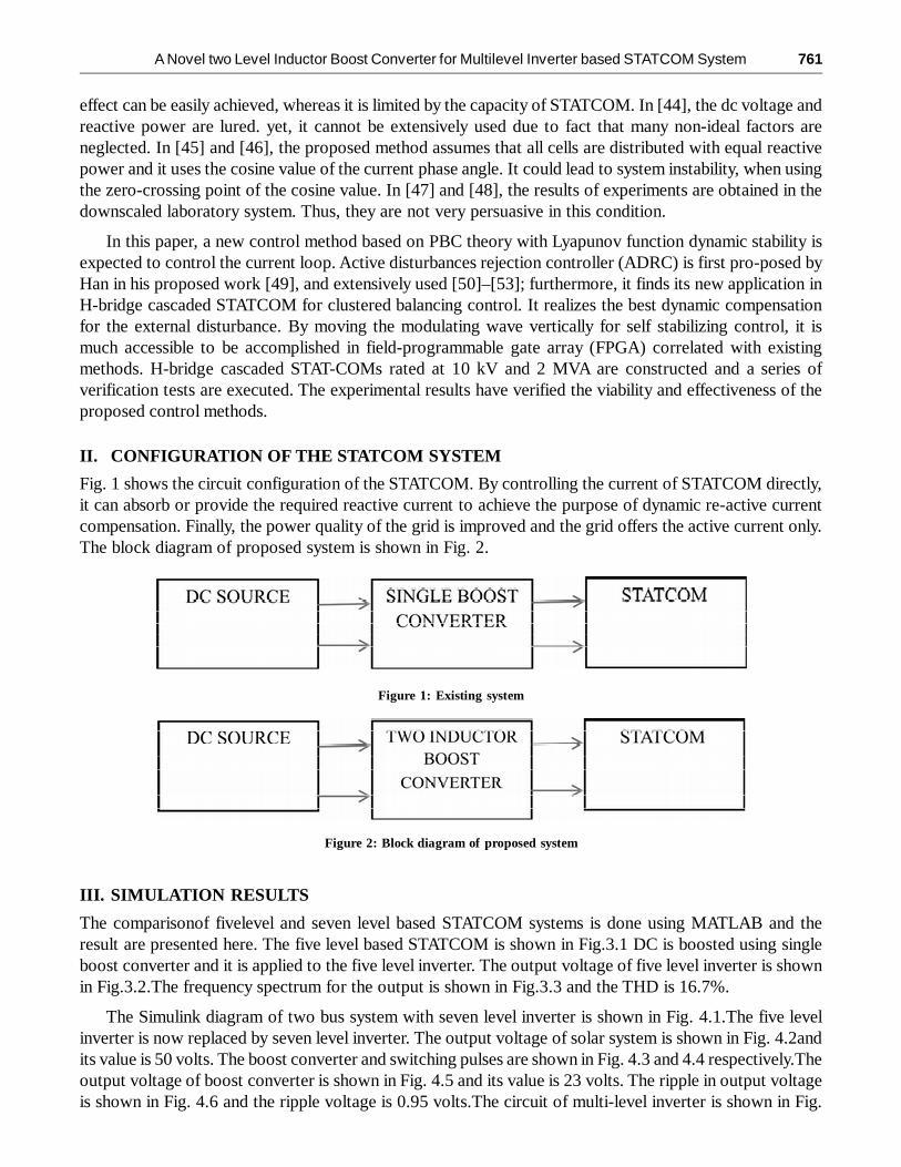
4.7.The switching pulse for multilevel inverter and output voltage of multilevel inverter is shown in Fig.4.8 and 4.9 respectively. The voltage across load 1, load 2 and STATCOM are shown in Fig. 4.10.
The real and reactive powers are shown in Fig.4.11.The frequency spectrum for the output of MLI isshown in Fig. 4.12 and the THD is 7.7%
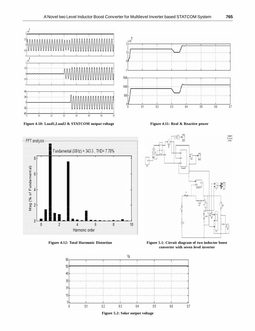
The boost converter is replaced with two inductor boost converter. The circuit of TIBC based sevenlevel inverter system is shown in Fig.5.1.The output voltage ofsolar system is shown in Fig.5.2.The TIBCand its pulses are shown in fig 5.3 and 5.4 respectively .The output voltage of two inductor boost converteris shown in Fig.5.5.Zoomed view of output voltage is shown in Fig.5.6.and the ripple voltage is 0.5 volts.The frequency spectrum is shown in Fig.5.7 and the THD is 6%.The summary of ripple voltage and THDis given in Table 1.
Table 1Comparison of Multilevel inverter
Multilevel inverter Vin Vo Ripple voltage THD
Five level 48v 200v - 16.76%
Seven level Single boost converter 48v 240v 0.95 7.78%
Seven level TIBC converter 48v 263v 0.53 6.00%
Figure 3.1: Circuit diagram of five level inverter
Figure 3.2: Five level inverter output voltage Figure 3.3: Total Harmonic Distortion

A Novel two Level Inductor Boost Converter for Multilevel Inverter based STATCOM System 763
Figure 4.1: Circuit diagram of single boost converter withseven level inverter
Figure 4.2: Solar output voltage
Figure 4.3: Single boost converter Figure4.4: Switching pulse for boost converter
Figure 4.5: Boost converter output voltage

764 G. Ramya and V. Ganapathy
Figure 4.6: Ripple output voltage
Figure 4.7: Multilevel inverter circuit diagram Figure 4.8: Switching pulse for inverter switch M1,M3
Figure 4.9.Multilevel inverter output voltage
A Novel two Level Inductor Boost Converter for Multilevel Inverter based STATCOM System 765
Figure 4.10: Load1,Load2 & STATCOM output voltage Figure 4.11: Real & Reactive power
Figure 4.12: Total Harmonic Distortion Figure 5.1: Circuit diagram of two inductor boostconverter with seven level inverter
Figure 5.2: Solar output voltage

766 G. Ramya and V. Ganapathy
Figure 5.3: Two inductor boost converter
Figure 5.4: Switching pulse for two inductor boost converter
Figure 5.5: Two inductor boost converter
Figure 5.6: Output ripple voltage

A Novel two Level Inductor Boost Converter for Multilevel Inverter based STATCOM System 767
Figure 5.7: Total Harmonic Distortion
CONCLUSION
Single boost and two inductor boost converter based seven level STATCOM system are successfully designed,modelled and simulated using MATLAB and the corresponding resultsare presented. The result identifiedthat ripple voltage and THD are minimum in the case of seven level TIBC based STATCOM system.Thereforethis system is a viable alternative to the existing STATCOM system
The present work deals with open loop controlled SBC and TIBC based STACOM systems. Theinvestigation on closed loop system will be done in future
REFERENCES[1] B. Gultekin and M. Ermis, “Cascaded multilevel converter-based transmission STATCOM: System design methodology
and development of a 12 kV ±12 MVAr power stage,” IEEE Trans. Power Electron., vol. 28, no. 11, pp. 4930–4950, Nov.2013.
[2] B. Gultekin, C. O. Gerc¸ek, T. Atalik, M. Deniz, N. Bic¸er, M. Ermis, K. Kose, C. Ermis, E. Koc¸, I. C¸ adirci, A. Ac¸ik, Y.Akkaya, H. Toygar, and S. Bideci, “Design and implementation of a 154-kV±50-Mvar transmission STATCOM based on21-level cascaded multilevel converter,” IEEETrans. Ind. Appl., vol. 48, no. 3, pp. 1030–1045, May/Jun. 2012.
[3] S. Kouro, M. Malinowski, K. Gopakumar, L. G. Franquelo, J. Pou, J. Rodriguez, B.Wu,M. A. Perez, and J. I. Leon,“Recent advances and industrial applications of multilevel converters,” IEEE Trans. Ind. Electron., vol. 57, no. 8, pp.2553–2580, Aug. 2010.
[4] F. Z. Peng, J.-S. Lai, J. W. McKeever, and J. VanCoevering, “A multilevel voltage-source inverter with separateDCsourcesfor static var generation,” IEEE Trans. Ind. Appl., vol. 32, no. 5, pp. 1130–1138, Sep./Oct. 1996.
[5] Y. S. Lai and F. S. Shyu, “Topology for hybrid multilevel inverter,” Proc. Inst. Elect. Eng.—Elect. Power Appl., vol. 149,no. 6, pp. 449–458, Nov. 2002.
[6] D. Soto and T. C. Green, “A comparison of high-power converter topologies for the implementation of FACTS controllers,”IEEE Trans. Ind.Electron., vol. 49, no. 5, pp. 1072 1080, Oct. 2002.
[7] C. K. Lee, J. S. K. Leung, S. Y. R. Hui, and H. S.-H. Chung, “Circuit-level comparison of STATCOM technologies,” IEEETrans. Power Electron., vol. 18, no. 4, pp. 1084–1092, Jul. 2003.
[8] H. Akagi, S. Inoue, and T. Yoshii, “Control and performance of a transformerlesscascade PWM STATCOM with starconfiguration,” IEEETrans. Ind. Appl., vol. 43, no. 4, pp. 1041–1049, Jul./Aug. 2007.
[9] A. H. Norouzi and A. M. Sharaf, “Two control scheme to enhance the dynamic performance of the STATCOM andSSSC,” IEEE Trans. Power Del., vol. 20, no. 1, pp. 435–442, Jan. 2005.

768 G. Ramya and V. Ganapathy
[10] C. Schauder, M. Gernhardt, E. Stacey, T.Lemak, L. Gyugyi, T. W. Cease, and A. Edris, “Operation of ±100 MVAr TVASTATCOM,” IEEE Trans.Power Del., vol. 12, no. 4, pp. 1805–1822, Oct. 1997.
[11] C. H. Liu and Y. Y. Hsu, “Design of a self-tuning PI controller for a STATCOM using particle swarm optimization,” IEEETrans. Ind. Electron., vol. 57, no. 2, pp. 702–715, Feb. 2010.
[12] S. Mohagheghi, Y. Del Valle, G. K. Venayagamoorthy, and R. G. Harley, “A proportional-integrator type adaptive criticdesign-based neurocontrollerfor a static compensator in a multimachine power system,” IEEETrans. Ind. Electron., vol.54, no. 1, pp. 86–96, Feb. 2007.
[13] H. F. Wang, H. Li, and H. Chen, “Application of cell immune responsemodelling to power system voltage control bySTATCOM,” Proc. Inst.Elect.Eng. Gener.Transm.Distrib., vol. 149, no. 1, pp. 102–107, Jan. 2002.
[14] A. Jain, K. Joshi, A. Behal, and N. Mohan, “Voltage regulation with STATCOMs: Modeling, control and results,” IEEETrans. Power Del., vol. 21, no. 2, pp. 726–735, Apr. 2006.
[15] V. Spitsa, A. Alexandrovitz, and E. Zeheb, “Design of a robust state feedback controller for a STATCOM using a zero setconcept,” IEEETrans. Power Del., vol. 25, no. 1, pp. 456–467, Jan. 2010.
[16] C. D. Townsend, T. J. Summers, and R. E. Betz, “Multigoal heuristic model predictive control technique applied to acascaded H-bridge STATCOM,” IEEE Trans. Power Electron., vol. 27, no. 3, pp. 1191–1200, Mar. 2012.
[17] C. D. Townsend, T. J. Summers, J. Vodden, A. J. Watson, R. E. Betz, and J. C. Clare, “Optimization of switching lossesand capacitor voltage ripple using model predictive control of a cascaded H-bridge multilevel STATCOM,” IEEE Trans.Power Electron., vol. 28, no. 7, pp. 3077–3087, Jul. 2013.
[18] Y. Shi, B. Liu, and S. Duan, “Eliminating DC current injection in currenttransformer- sensed STATCOMs,” IEEE Trans.Power Electron., vol. 28, no. 8, pp. 3760–3767, Aug. 2013.
[19] B. Singh and S. R. Arya, “Adaptive theory-based improved linear sinusoidal tracer control algorithm for DSTATCOM,”IEEE Trans. PowerElectron., vol. 28, no. 8, pp. 3768–3778, Aug. 2013.
[20] S. R. Arya and B. Singh, “Performance of DSTATCOM using leaky LMS control algorithm,” IEEE J. Emerging Select.Topics Power Electron.,vol. 1, no. 2, pp. 104–113, Jun. 2013.
[21] P. Petitclair, S. Bacha, and J.-P.Fe rrieux, “Optimized linearization via feedback control law for a STATCOM,” in Proc.IEEE Ind. Appl. Soc.Annu. Meeting, 1997, pp. 880–885.
[22] H. Khalil, Nonlinear Systems, 3rd ed. Englewood Cliffs, NJ, USA: Prentice-Hall, 2002.
[23] Y. Han, Y. O. Lee, and C. C. Chung, “Modified non-linear damping of internal dynamics via feedback linearisation forstatic synchronous compensator,” IET Gener. Transm.Distrib., vol. 5, no. 9, pp. 930–940, 2011.
[24] Y. O. Lee, Y. Han, and C. C. Chung, “Output tracking control with enhanced damping of internal dynamics and its outputboundedness for STATCOM system,” IET Control Theory Appl., vol. 6, no. 10, pp. 1445– 1455, 2012.
[25] Y. O. Lee, Y. Han, and C. C. Chung, “Output tracking control with enhanced damping of internal dynamics and its outputboundedness,” in Proc. IEEE Conf. Decision Control, 2010, pp. 3964–3971.
[26] Y. Han, Y. O. Lee, and C. C. Chung, “A modified nonlinear damping of zero-dynamics via feedback control for a STATCOM,”in Proc. IEEEPowerTech, 2009, pp. 880–885.
[27] G. E. Valderrama, P. Mattavelli, and A. M. Stankovic, “Reactive power and imbalance compensation using STATCOMwith dissipativity-based control,” IEEE Trans. Control Syst. Technol., vol. 9, no. 5, pp. 718–727, Sep. 2001.
[28] H. Tsai, C. Chu, and S. Lee, “Passivity-based nonlinear STATCOM controller design for improving transient stability ofpower systems,” presented at the IEEE/PES Transmission and Distribution Conference &Exhibition: Asia and Pacific,Dalian, China, 2005.
[29] Y. Gui, Y. O. Lee, H. J. Kang, Y. Han, and C. C. Chung, “Novel passivitybasedcontroller design for STATCOM,” inpresented at the 2011 11thInternationalConference on Control, Automation and Systems, Gyeonggido, Korea, Oct. 26–29,2011, pp. 556–560.
[30] Y. Gui, Y. O. Lee, Y. Han, W. Kim, and C. C. Chung, “Passivity-based control with nonlinear damping for STATCOMsystem,” in Proc. 51stIEEE Conf. Decision Control, Maui, HI, Dec. 10–13, 2012, pp. 3964–3971.
[31] F. Z. Peng,W. S. John, and D. A. Adams, “A power line conditioner using cascade multilevel inverters for distributionsystems,” IEEE Trans. Ind.Appl., vol. 34, no. 6, pp. 1293–1298, Nov./Dec. 1998.
[32] W. Jun and K. M. Smedley, “Synthesis of multilevel converters based on single- and/or three-phase converter buildingblocks,” IEEE Trans. PowerElectron., vol. 23, no. 3, pp. 1247–1256, May 2008.
[33] C. H. Ng, M. A. Parker, R. Li, P. J. Tavner, J. R. Bumby, and E. Spooner, “A multilevel modular converter for a large, lightweight wind turbine generator,” IEEE Trans. Power Electron., vol. 23, no. 3, pp. 1062–1074, May 2008.

A Novel two Level Inductor Boost Converter for Multilevel Inverter based STATCOM System 769
[34] J. Geng, “Modeling and controlling of cascade static synchronous compensator,” Ph.D. dissertation, Dept. Electr.Eng.,Tsinghua Univ., Beijing, China, 2003.
[35] R. E. Betz and T. J. Summers, “Using a cascaded H-bridge STATCOM for rebalancing unbalanced voltages,” presented atthe 7th International Conference on Power Electronics, Daegu, Korea, Oct. 2007.
[36] N. Hatano and T. Ise, “A configuration and control method of cascade HbridgeSTATCOM,” presented at the IEEE PowerEnergy Society General Meeting, Pittsburgh, PA, USA, Jul. 2008.
[37] T. Yoshii, S. Inoue, and H. Akagi, “Control and performance of a mediumvoltagetransformerless cascade PWM STATCOMwith star configuration,” presented at the IEEE Industry Applications Conference, Tampa, FL, USA, 2006.
[38] M. Hagiwara and H. Akagi, “Control and experiment of pulse width modulated modular multilevel converters,” IEEETrans. Power Electron., vol. 24, no. 7, pp. 1737–1746, Jul. 2009.
[39] Z. Liu, B. Y. Liu, S. X. Duan, and Y. Kang, “A novel DC capacitor voltage balance control method for cascade multilevelSTATCOM,” IEEE Trans.Power Electron., vol. 27, no. 1, pp. 14–27, Jan. 2012.
[40] L. M. Tolbert, J. N. Chiasson, and F. Z. Peng, “Modulation index regulation of a multilevel inverter for static varcompensation,” in presented at the Power Engineering Society General Meeting, Toronto, ON, Canada, 2003, p. 199.
[41] Q. Song, W. Liu, Z. Yuan, W. Wei, and Y. Chen, “DC voltage balancingtechnique using multi-pulse optimal PWM forcascade H-bridge inverters based STATCOM,” in Proc. IEEE 35th Annu. Power Electron. Spec. Conf.,Aachen, Germany,Jun. 20–25, 2004, pp. 4768–4772.
[42] Q. Song, W. Liu, Z. Yuan, W. Wei, and Y. Chen, “DC voltage balancing technique using multi-pulse optimal PWM forcascade H-bridge inverters based STATCOM,” in Proc. Appl. Power Electron. Conf. Expo., Anaheim,CA, 2004, pp.4768–4772.
[43] Y. Li and B. Wu, “A novel DC voltage detection technique in the CHB inverter-based STATCOM,” IEEE Trans. PowerDel., vol. 23, no. 3,pp. 1613–1619, Jul. 2008.
[44] S. Sirisukprasert, A. Q. Huang, and J.-S. Lai, “Modeling, analysis and control of cascaded-multilevel converter-basedSTATCOM,” presented at the IEEE Power Engineering Society General Meeting, Toronto, ON,Canada, Jul. 2003.
[45] J. A. Barrena, L. Marroyo, M.A.Rodriguez, O. Alonso, and J. R. Torrealday, “DC voltage balancing for PWM cascadedH-bridge converter based STATCOM,” in Proc. 32nd Annu. Conf. Ind. Electron.,Paris, France, 2006, pp. 1840–1845.
[46] J. A. Barrena, L.Marroyo, M. A. R.Vidal, and J. R. T.Apraiz, “Individual voltage balancing strategy for PWM cascaded H-bridge converter based STATCOM,” IEEE Trans. Ind. Electron., vol. 55, no. 1, pp. 21–29, Jan. 2008.
[47] K. Sano and M. Takasaki, “A transformerless D-STATCOM based on a multivoltage cascade converter requiring no DCsources,” IEEE Trans. Power Electron., vol. 27, no. 6, pp. 2783–2795, Jun. 2012.
[48] S. Du, J. Liu, J. Lin, and Y. He, “A novel DC voltage control method for STATCOM based on hybrid multilevel H-bridgeconverter,” IEEE Trans.Power Electron., vol. 28, no. 1, pp. 101–111, Jan. 2013.
[49] J. Q. Han, “Auto-disturbance rejection control and applications,” Control Decision, vol. 13, pp. 19–23, 1998.
[50] J. Q. Han, “From PID to active disturbance rejection control,” IEEE Trans.Ind. Electron.,vol. 56, no. 3, pp. 900–906, Mar.2009.
[51] D.Wu, “Design and analysis of precision active disturbance rejection control for noncircular turning process,” IEEETrans. Ind. Electron., vol. 56,no. 7, pp. 2746–2753, Jul. 2009.
[52] Q. Zheng, L. L. Dong, and Z. Gao, “Control and rotation rate estimation of vibrational MEMS gyroscopes,” in Proc. IEEEInt. Conf. Control Appl.,Piscataway, NJ, 2007, pp. 118–123.
[53] W. Zhou and Z. Gao, “An active disturbance rejection approach to tension and velocity regulations in web processinglines,” in Proc. IEEE Int. Conf. Control Appl., Piscataway, NJ, 2007, pp. 842–848.
[54] R. Ortega, A. Loria, P. J. Nicklasson, and H. Sira-Ramirez, Passivity-Based Control of Euler-Lagrange Systems: MechanicalElectrical and Electromechanical Application. London, U.K.: Springer-Verlag, 1998.
[55] L. Maharjan, S. Inoue, and H. Akagi, “Atransformerless energy storage system based on a cascade multilevel PWMconverter with star configuration,”IEEE Trans. Ind. Appl., vol. 44, no. 5, pp. 1621–1630, Sep./Oct.2008.