Embed Size (px)
Citation preview

EMERSON & CUMING Tel: +32-14-56 25 00 MICROWAVE PRODUCTS N.V. Fax: +32-14-56 25 01 Nijverheidsstraat 7A 2260 WESTERLO-BELGIUM
WW
W.EC
COSO
RB.C
OM
A numerical comparison of the reflectivity of thick-sheet and thin-foil hollow pyramidal absorbers
Hugo Pues and Yoeri Ariën, Emerson & Cuming Microwave Products, April 2008
Abstract The reflectivity of a doubly-periodic array of hollow pyramidal absorbers (representing a typical absorber-lined wall of a large 10 m EMC test chamber) is calculated in two ways. First, a rigorous full-wave electromagnetic solver is used in the frequency range of 10 MHz to ≥ 2 GHz. Second, an approximate ray-tracing method is used that is valid at higher frequencies (i.e. above 5 or 10 GHz). In this way a numerical comparison is made of a thick-sheet and a thin-foil hollow pyramidal absorber. Both types have sharp tips, a height of 102.7”, base dimensions of 24” x 24”, and a low-frequency sheet impedance of 100 Ω per square. Their calculated performance is very similar at low frequencies (below 500 MHz), but largely different at high frequencies (above 1 GHz). At these high frequencies the reflectivity of the thin-foil absorber appears to fully collapse, whereas the reflectivity of the thick-sheet absorber continues to improve with frequency.
Introduction Since a number of years, hollow pyramidal absorbers appear to be the preferred absorber choice for 10 m EMC test chambers due to their excellent wideband performance, light weight, easy installation and low cost [1]. Historically, Emerson & Cuming Microwave Products has introduced two generations of hollow pyramidal absorbers:
• The first generation ECCOSORB HPY-NRL [2] had sharp tips and was built of two-layered absorbing panels. It was developed for use in antenna and RCS test chambers, but has also been used a lot in large EMC test chambers until the introduction of the second generation.
• The second generation ECCOSORB HX-NRL [3] had truncated tips and was built of single-layered absorbing panels. It was optimized for use in EMC test chambers that needed to meet the volumetric ± 4 dB NSA requirements in the 30-1000 MHz range [4], but still had to perform very well at higher frequencies. To achieve this objective, absorbing layers of 18 mm thickness were used.
Since its introduction in the CESI chamber [5], ECCOSORB HX-NRL has been optimized continuously to better meet the anechoic requirements of EMC test chambers, but the basic concept of using absorbing layers of about 18 mm thickness, was always maintained. However, in the mean time an alternative configuration has been introduced in the market where these electrically thick absorbing sheets have been replaced by electrically thin foils of well-controlled conductivity. This not only resulted in material savings and weight reduction, but also allowed to improve the flammability ratings of the absorber. Concerning the possible detrimental effect of this shrinkage of the absorbing layer thickness on the absorber performance at higher frequencies, largely different opinions have been expressed. However, as far as we know, no comparative results of a rigorous unambiguous evaluation (either theoretical, numerical or experimental) of thick-sheet and thin-foil pyramidal absorbers have been published up to now. In this paper we use CST’s Microwave Studio [6] to perform a rigorous investigation at low and medium frequencies (up to ≥ 2 GHz). We also use an approximate ray-tracing calculation method that should be valid at high frequencies (i.e. above 5 or 10 GHz).

EMERSON & CUMING Tel: +32-14-56 25 00 MICROWAVE PRODUCTS N.V. Fax: +32-14-56 25 01 Nijverheidsstraat 7A 2260 WESTERLO-BELGIUM
WW
W.EC
COSO
RB.C
OM
Description of the absorber models
Figure 1: Geometric absorber model.
Figure 1 shows the absorber structure that was modeled. It concerns a hollow pyramid with a base surface of 61 cm x 61 cm (24” x 24”) and a height of 261 cm (102.7”). To simplify the model, the tips were not truncated and all internal materials were removed. Hence the model only consisted of four triangular sheets forming a hollow pyramid with a metal ground plane. Both a thick-sheet version (resembling ECCOSORB HX-NRL) and a thin-foil version (resembling a competitive foil absorber) were modeled. The thin-foil model consisted of four homogeneous triangles with a negligibly small thickness and a frequency-independent sheet impedance
squareRs /100 Ω= (1) The thick-sheet model consisted of four homogeneous triangles of 18 mm thickness whose dielectric properties were modeled by
0.100.21' −+= GHzfε (2) and
0.10.10" −= GHzfε (3)
where 'ε and "ε are the real and imaginary part of the complex relative permittivity and GHzf is the frequency expressed in GHz. The models given by equations (1) through (3) were derived from real measurement data although they may not represent the optimal values for this particular height of absorber. They can be considered as ball-park models that are representative of real data. When deriving these models, we also made sure that both models did have the same sheet impedance (i.e. 100 Ω/square) in the low-frequency limit where the electrical thickness of the thick-sheet material can be considered to be negligibly small.
EMERSON & CUMING Tel: +32-14-56 25 00 MICROWAVE PRODUCTS N.V. Fax: +32-14-56 25 01 Nijverheidsstraat 7A 2260 WESTERLO-BELGIUM
WW
W.EC
COSO
RB.C
OM
Rigorous numerical simulations Infinite two-dimensional arrays of the two above types of pyramidal absorbers were simulated using the frequency domain solver of MWS (Microwave Studio). Particularly, the metal-backed plane-wave reflectivity was calculated. Figure 2 shows the definition of the incident angle and polarization (TE or TM).
Figure 2: Plane-wave incidence on an absorber-lined wall.
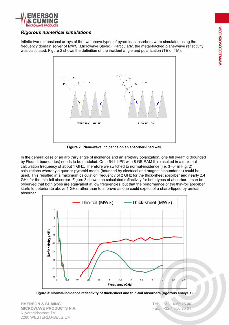
In the general case of an arbitrary angle of incidence and an arbitrary polarization, one full pyramid (bounded by Floquet boundaries) needs to be modeled. On a 64-bit PC with 8 GB RAM this resulted in a maximal calculation frequency of about 1 GHz. Therefore we switched to normal-incidence (i.e. ϑ=0° in Fig. 2) calculations whereby a quarter-pyramid model (bounded by electrical and magnetic boundaries) could be used. This resulted in a maximum calculation frequency of 2 GHz for the thick-sheet absorber and nearly 2.4 GHz for the thin-foil absorber. Figure 3 shows the calculated reflectivity for both types of absorber. It can be observed that both types are equivalent at low frequencies, but that the performance of the thin-foil absorber starts to deteriorate above 1 GHz rather than to improve as one could expect of a sharp-tipped pyramidal absorber.
-40
-35
-30
-25
-20
-15
-10
-5
0
0 0,2 0,4 0,6 0,8 1 1,2 1,4 1,6 1,8 2 2,2 2,4
Frequency (GHz)
Ref
lect
ivity
(dB
)
Thin-foil (MWS) Thick-sheet (MWS)
Figure 3: Normal-incidence reflectivity of thick-sheet and thin-foil absorbers (rigorous analysis).

EMERSON & CUMING Tel: +32-14-56 25 00 MICROWAVE PRODUCTS N.V. Fax: +32-14-56 25 01 Nijverheidsstraat 7A 2260 WESTERLO-BELGIUM
WW
W.EC
COSO
RB.C
OM
Approximate high-frequency analysis Although it would be possible to run the above simulations up to higher frequencies by using a more powerful computer, there is always a limit to such an effort. Therefore we also performed an approximate ray-tracing analysis of the same normal-incidence case. This analysis should be sufficiently accurate to give us a good idea of the performance at frequencies above 5 or 10 GHz where the wavelength has decreased to 1/10th or 1/20th of the base dimensions (24” x 24”). In our ray-tracing analysis we no longer consider a large plane wave front (which we could consider as a low-frequency ray) that is incident on the absorber-lined wall, but we track the various “optical” rays that are incident on it and locally behave as plane waves. If such a high-frequency ray is normally incident on a wall that is lined with 102.7” pyramids (i.e. ϑ=0° in Fig. 2), it will hit one of the absorbing triangles at an incident angle of 83.33°. This incident angle (α) and the usual orthogonal polarizations (TE and TM) are defined in Fig. 4.
Figure 4: Plane-wave incidence on an absorbing sheet.
As shown in Fig. 4, part of the incident power will be reflected and part will be transmitted by the absorbing sheet (with the balance being absorbed). The corresponding reflection and transmission coefficients depend on the frequency, incident angle and polarization state as well as the material properties and thickness of the sheet. Let us first consider the part that is reflected by the absorbing sheet. Because of the shape of the absorber lining, the energy that is reflected off an absorber triangle will hit a neighboring pyramid where the same process will occur (part will be absorbed, part will be reflected and part will be transmitted). Normally this process will happen many times again before a ray will be bounced off the absorber-lined wall so that we can assume that almost all incident energy will be absorbed. Hence, we will neglect this reflected ray in our approximate analysis.

EMERSON & CUMING Tel: +32-14-56 25 00 MICROWAVE PRODUCTS N.V. Fax: +32-14-56 25 01 Nijverheidsstraat 7A 2260 WESTERLO-BELGIUM
WW
W.EC
COSO
RB.C
OM
Let us now consider the part that is transmitted by the absorbing sheet. It will hit the metal backing, be fully reflected by it and impinge again on the inner side of the absorbing triangle where the same process will occur again. Hence part of this ray will be transmitted again and be bounced off the absorber-lined wall. In our approximate analysis we have assumed that this ray which is transmitted twice by the same triangle is the dominant reflectivity effect of the absorber at high frequencies and that all other contributions to the reflectivity can be neglected in a first approximation. Therefore; assuming an ip -polarized incident ray (where ip can be TE, TM or a combination of both), we can derive the following high-frequency formula for the reflectivity:
( ) dBttyreflectivi ipGHzf2
5log20≈
>> (4)
where ipt is the transmission coefficient for an ip -polarized ray. It can be verified easily that the minimum and maximum values of ipt are given by TEt and TMt . These coefficients can be easily calculated using MWS (or even a much simpler program) and are shown in Figure 5 in the frequency range of 10 MHz to 10 GHz for both the thin-foil and thick-sheet absorber.
Angle of incidence 83.33°
-30
-25
-20
-15
-10
-5
0
0.01 0.1 1 10
Frequency (GHz)
Tran
smis
sion
coe
ffici
ent (
dB)
Thin-foil TE Thin-foil TMThick-sheet TE Thick-sheet TM
Figure 5: Transmission coefficients of absorbing sheets.
It can be seen that TMt exceeds TEt for both the thin-foil and thick-sheet absorber. Hence, it follows from (4) that the worst-case high-frequency reflectivity is given by
( ) dBttyreflectiviTMray TMGHzf2
5log20≈
>> (5)
This worst-case reflectivity was calculated for both types of absorbers and is shown in Fig. 6 from 5 to 10 GHz. It can be seen that this TMray reflectivity is dramatically poor (about –3.5 dB) for the thin-foil absorber whereas it is better than -40 dB for the thick-sheet one. For comparison, Fig. 6 also shows the rigorous results that were obtained by using MWS and were already shown in Figure 3.

EMERSON & CUMING Tel: +32-14-56 25 00 MICROWAVE PRODUCTS N.V. Fax: +32-14-56 25 01 Nijverheidsstraat 7A 2260 WESTERLO-BELGIUM
WW
W.EC
COSO
RB.C
OM
Typically, if a plane wave is incident on a pyramid, the incident polarization will be TE on two triangles of the pyramid and TM on the two other ones. Hence, one can assume that at very high frequencies the overall plane-wave reflectivity of the absorber-lined wall will be given by
( ) dBtttyreflectiviWall TMTEGHzf2/log20 22
5+≈
>> (6)
This high-frequency wall reflectivity has also been plotted in Fig. 6 between 5 and 10 GHz.
-50
-45
-40
-35
-30
-25
-20
-15
-10
-5
0
0,01 0,1 1 10
Frequency (GHz)
Ref
lect
ivity
(dB
)
Thin-foil (MWS) Thin-foil (TM ray)Thin-foil (Wall) Thick-sheet (MWS)Thick-sheet (TM ray) Thick-sheet (Wall)
Figure 6: Reflectivity of thick-sheet and thin-foil absorber (rigorous & approximate analysis).
Conclusion Thin-foil hollow pyramidal absorbers can be equivalent to thick-sheet hollow pyramidal absorbers at low frequencies (up to about 500 MHz in our calculation example). However, as shown by the numerical simulations described in this paper, the thin-foil principle badly collapses at higher frequencies making it unsuitable for many new EMC test chambers that have to meet stringent requirements in the GHz range.

EMERSON & CUMING Tel: +32-14-56 25 00 MICROWAVE PRODUCTS N.V. Fax: +32-14-56 25 01 Nijverheidsstraat 7A 2260 WESTERLO-BELGIUM
WW
W.EC
COSO
RB.C
OM
Acknowledgment We would like to thank Dr. Frank Demming-Janssen of CST for his support and collaboration in the simulations of the different structures.
References [1] F.-W. Trautnitz, EMC Absorbers through the Years with Respect to the New Site VSWR Validation
Procedure in the Frequency Range from 1 to 18 GHz - a Practical Approach, IEEE 2007 International Symposium on Electromagnetic Compatibility, Honolulu, HI, 9-13 July 2007, pp. 1-6.
[2] ECCOSORB HPY-NRL, www.eccosorb.com. [3] ECCOSORB HX-NRL, www.eccosorb.com. [4] CISPR 16-1-4 (2nd edition, 2007-02), Specification for radio disturbance and immunity measuring
apparatus and methods – Part 1-4: Radio disturbance and immunity measuring apparatus – Ancillary equipment – Radiated disturbances.
[5] B. Audone, L. Bolla, G.Costa, A Manara, H. Pues, Design and engineering of a large shielded semi-
anechoic chamber meeting the volumetric NSA requirements at 3 and 10 m transmission length, IEEE 1993 International Symposium on Electromagnetic Compatibility, Dallas, TX, 9-13 Aug. 1993, pp. 379-384.
[6] CST MICROWAVE STUDIO, www.cst.com.