Embed Size (px)
Citation preview
Advanced Steel Construction Vol. 10, No. 1, pp. 53-71 (2014) 53
A PARAMETRIC STUDY ON SEISMIC CHARACTERISTICS OF COLD-FORMED STEEL SHEAR WALLS BY
FINITE ELEMENT MODELING
S. Hatami1,*, A. Rahmani2, A. Parvaneh3 and H.R. Ronagh4
1Assistant Professor, Department of Civil Engineering, Yasouj University, Yasouj, Iran 2Graduate Student, Department of Civil Engineering, Islamic Azad University, Bushehr, Iran
3Former Graduate Student, Department of Civil Engineering, Sharif University of Technology, Tehran, Iran 4Senior lecturer, School of Civil Engineering, The University of Queensland, Brisbane, Australia
*(Corresponding author: E-mail: hatami@ yu.ac.ir)
Received: 12 July 2012; Revised: 17 October 2012; Accepted: 5 December 2012
ABSTRACT: Shear wall panels, including cold-formed steel frames and its attached sheathing, are common lateral load resisting systems of cold-formed steel structures. In this paper, the finite element method is used to study the lateral performance of shear wall panels. The finite element model is validated against experimental results of other researchers. Using the validated model, a parametric study is described to determine strength, drift and seismic behavior of the shear wall panels. Based on the results, it is concluded that the initial stiffness and ultimate lateral strength are dramatically affected by the thickness of the frame members, type of sheathing material, edge screw spacing, height of the frame, while some parameters such as field screw spacing have a minor effect on the initial stiffness and the ultimate lateral strength. In addition, this study looks into the earthquake performance of the shear wall panels and presents the corresponding ductility factor and force reduction factor (R-factor) of shear wall panels.
Keywords: Cold-formed steel, shear wall, light steel framing, racking performance, lateral strength, drift ratio, R factor
1. INTRODUCTION Light-weight construction leads to saving in materials, transportation and installation costs. On the other hand, it reduced dead load and decreases its earthquake load demand. Light Steel Framing (LSF), in addition to being light, is a structural system with potential for industrial production and pre-fabrication which can meet qualitative and quantitative demands of an advanced construction industry. In earthquake prone areas, an important consideration in the performance of LSF is its behavior against seismic loads. The main component to resist earthquake forces in a light steel building is shear wall. Shear walls in LSF are cold-formed steel frames braced by diagonal steel straps or sheathed with steel sheets or shear panels. The most common types of shear panels are made from wood-based or gypsum-based materials; panels are generally connected to the frame members by self-drillings screws. During the two last decades, some experimental and theoretical studies have been conducted in relation with seismic behavior of shear wall panels. Determination of lateral strength and ductility of the shear walls, as the fundamental characteristic of seismic design, has been the main scope of these studies. Serrette et al. [1,2] conducted a series of tests on shear wall panels in cold-formed steel framing with different sheathing materials, such as gypsum wall board (GWB), oriented strand board (OSB), and plywood. Their results contributed to the development of the Standard for Cold-Formed Steel Framing-Lateral Design published by the American Iron and Steel Institute [3]. Rogers et al. [4] performed tests of shear wall panels with American and Canadian wood-based sheathing materials. The objective was to develop design guidelines for seismic application of shear wall panels to be adopted for the National Building Code of Canada. Fulop and Dubina [5] conducted a series of tests for determining the lateral strength of shear wall panels. They proposed a
54 A Parametric Study on Seismic Characteristics of Cold-Formed Steel Shear Walls by Finite Element Modeling
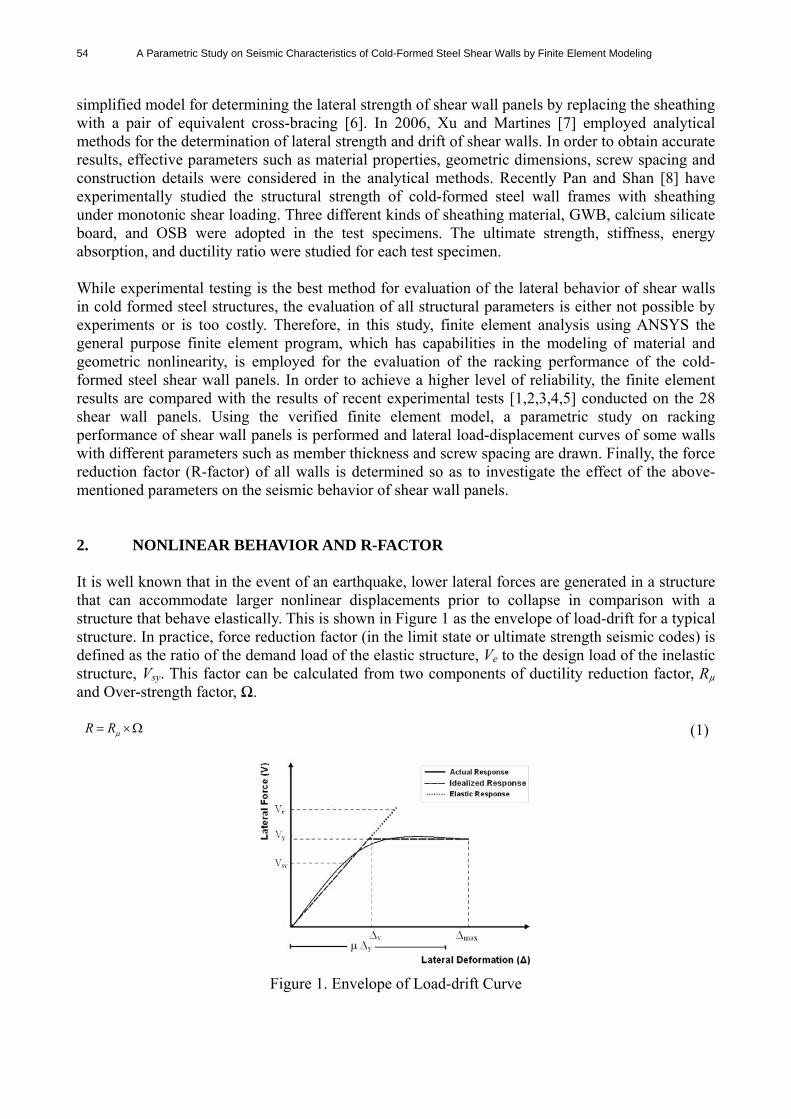
simplified model for determining the lateral strength of shear wall panels by replacing the sheathing with a pair of equivalent cross-bracing [6]. In 2006, Xu and Martines [7] employed analytical methods for the determination of lateral strength and drift of shear walls. In order to obtain accurate results, effective parameters such as material properties, geometric dimensions, screw spacing and construction details were considered in the analytical methods. Recently Pan and Shan [8] have experimentally studied the structural strength of cold-formed steel wall frames with sheathing under monotonic shear loading. Three different kinds of sheathing material, GWB, calcium silicate board, and OSB were adopted in the test specimens. The ultimate strength, stiffness, energy absorption, and ductility ratio were studied for each test specimen. While experimental testing is the best method for evaluation of the lateral behavior of shear walls in cold formed steel structures, the evaluation of all structural parameters is either not possible by experiments or is too costly. Therefore, in this study, finite element analysis using ANSYS the general purpose finite element program, which has capabilities in the modeling of material and geometric nonlinearity, is employed for the evaluation of the racking performance of the cold-formed steel shear wall panels. In order to achieve a higher level of reliability, the finite element results are compared with the results of recent experimental tests [1,2,3,4,5] conducted on the 28 shear wall panels. Using the verified finite element model, a parametric study on racking performance of shear wall panels is performed and lateral load-displacement curves of some walls with different parameters such as member thickness and screw spacing are drawn. Finally, the force reduction factor (R-factor) of all walls is determined so as to investigate the effect of the above-mentioned parameters on the seismic behavior of shear wall panels. 2. NONLINEAR BEHAVIOR AND R-FACTOR It is well known that in the event of an earthquake, lower lateral forces are generated in a structure that can accommodate larger nonlinear displacements prior to collapse in comparison with a structure that behave elastically. This is shown in Figure 1 as the envelope of load-drift for a typical structure. In practice, force reduction factor (in the limit state or ultimate strength seismic codes) is defined as the ratio of the demand load of the elastic structure, Ve to the design load of the inelastic structure, Vsy. This factor can be calculated from two components of ductility reduction factor, Rµ and Over-strength factor, Ω.
RR (1)
Figure 1. Envelope of Load-drift Curve
S. Hatami, A. Rahmani, A. Parvaneh and H.R. Ronagh 55
Rµ is the ratio of the demand of the elastic structure to that of the inelastic structure.
VV
y
eR (2)
Rµ is proportional to the structure ductility factor, µ. The ductility factor can be determined by dividing the maximum displacement of the nonlinear structure Δmax to displacement of yielding point of ideal model, Δy (Figure 1).
y max (3) Different relations have been presented for determination of the ductility reduction factor, Rµ, in the literature. On the basis of the natural period of the structure, T, Newmark and Hall [9] developed the following relations in terms of μ for the ductility reduction factor.
sec5.0 TR (4)
sec5.01.012 TR (5) sec03.01 TR (6)
The over-strength factor results from the strength that the structure undergoes beyond the design strength (Vsy) and can be expressed by Eq. 7.
VV syy (7)
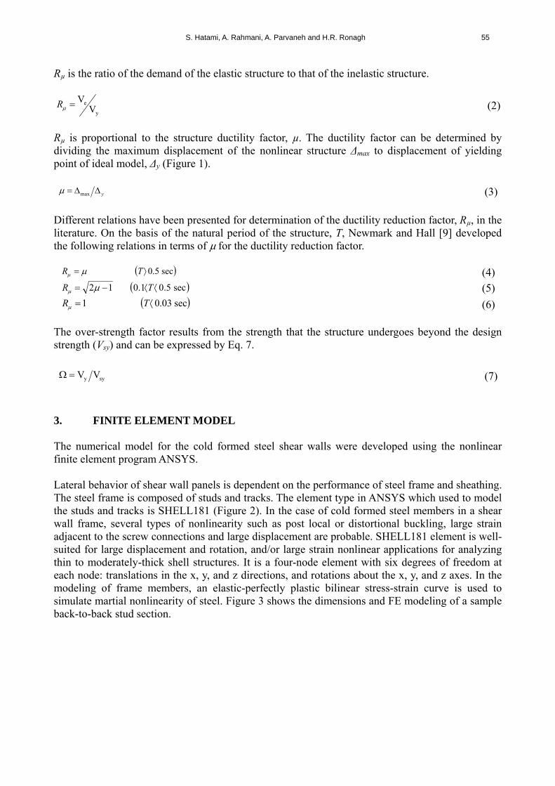
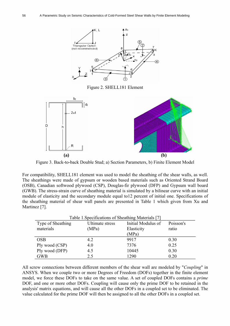
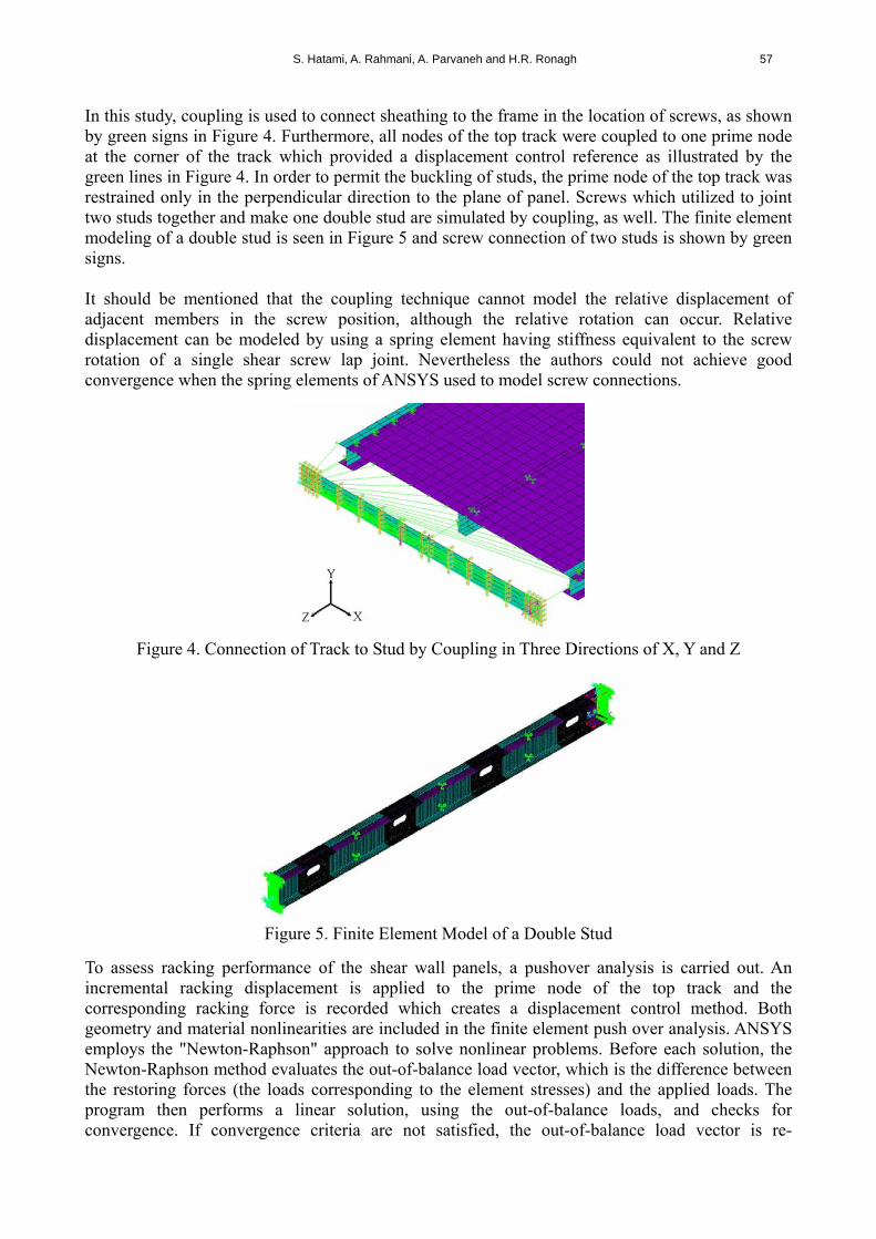
3. FINITE ELEMENT MODEL The numerical model for the cold formed steel shear walls were developed using the nonlinear finite element program ANSYS. Lateral behavior of shear wall panels is dependent on the performance of steel frame and sheathing. The steel frame is composed of studs and tracks. The element type in ANSYS which used to model the studs and tracks is SHELL181 (Figure 2). In the case of cold formed steel members in a shear wall frame, several types of nonlinearity such as post local or distortional buckling, large strain adjacent to the screw connections and large displacement are probable. SHELL181 element is well-suited for large displacement and rotation, and/or large strain nonlinear applications for analyzing thin to moderately-thick shell structures. It is a four-node element with six degrees of freedom at each node: translations in the x, y, and z directions, and rotations about the x, y, and z axes. In the modeling of frame members, an elastic-perfectly plastic bilinear stress-strain curve is used to simulate martial nonlinearity of steel. Figure 3 shows the dimensions and FE modeling of a sample back-to-back stud section.
56 A Parametric Study on Seismic Characteristics of Cold-Formed Steel Shear Walls by Finite Element Modeling
Figure 2. SHELL181 Element
(a) (b)
Figure 3. Back-to-back Double Stud; a) Section Parameters, b) Finite Element Model
For compatibility, SHELL181 element was used to model the sheathing of the shear walls, as well. The sheathings were made of gypsum or wooden based materials such as Oriented Strand Board (OSB), Canadian softwood plywood (CSP), Douglas-fir plywood (DFP) and Gypsum wall board (GWB). The stress-strain curve of sheathing material is simulated by a bilinear curve with an initial module of elasticity and the secondary module equal to12 percent of initial one. Specifications of the sheathing material of shear wall panels are presented in Table 1 which given from Xu and Martinez [7].
Table 1.Specifications of Sheathing Materials [7]
Type of Sheathing materials
Ultimate stress (MPa)
Initial Modulus of Elasticity (MPa)
Poisson's ratio
OSB 4.2 9917 0.30 Ply wood (CSP) 4.0 7376 0.25 Ply wood (DFP) 4.5 10445 0.30 GWB 2.5 1290 0.20
All screw connections between different members of the shear wall are modeled by "Coupling" in ANSYS. When we couple two or more Degrees of Freedom (DOFs) together in the finite element model, we force these DOFs to take on the same value. A set of coupled DOFs contains a prime DOF, and one or more other DOFs. Coupling will cause only the prime DOF to be retained in the analysis' matrix equations, and will cause all the other DOFs in a coupled set to be eliminated. The value calculated for the prime DOF will then be assigned to all the other DOFs in a coupled set.
S. Hatami, A. Rahmani, A. Parvaneh and H.R. Ronagh 57
In this study, coupling is used to connect sheathing to the frame in the location of screws, as shown by green signs in Figure 4. Furthermore, all nodes of the top track were coupled to one prime node at the corner of the track which provided a displacement control reference as illustrated by the green lines in Figure 4. In order to permit the buckling of studs, the prime node of the top track was restrained only in the perpendicular direction to the plane of panel. Screws which utilized to joint two studs together and make one double stud are simulated by coupling, as well. The finite element modeling of a double stud is seen in Figure 5 and screw connection of two studs is shown by green signs. It should be mentioned that the coupling technique cannot model the relative displacement of adjacent members in the screw position, although the relative rotation can occur. Relative displacement can be modeled by using a spring element having stiffness equivalent to the screw rotation of a single shear screw lap joint. Nevertheless the authors could not achieve good convergence when the spring elements of ANSYS used to model screw connections.
Figure 4. Connection of Track to Stud by Coupling in Three Directions of X, Y and Z
Figure 5. Finite Element Model of a Double Stud
To assess racking performance of the shear wall panels, a pushover analysis is carried out. An incremental racking displacement is applied to the prime node of the top track and the corresponding racking force is recorded which creates a displacement control method. Both geometry and material nonlinearities are included in the finite element push over analysis. ANSYS employs the "Newton-Raphson" approach to solve nonlinear problems. Before each solution, the Newton-Raphson method evaluates the out-of-balance load vector, which is the difference between the restoring forces (the loads corresponding to the element stresses) and the applied loads. The program then performs a linear solution, using the out-of-balance loads, and checks for convergence. If convergence criteria are not satisfied, the out-of-balance load vector is re-
58 A Parametric Study on Seismic Characteristics of Cold-Formed Steel Shear Walls by Finite Element Modeling
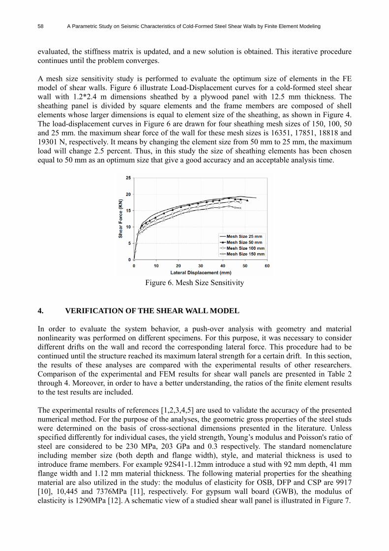
evaluated, the stiffness matrix is updated, and a new solution is obtained. This iterative procedure continues until the problem converges. A mesh size sensitivity study is performed to evaluate the optimum size of elements in the FE model of shear walls. Figure 6 illustrate Load-Displacement curves for a cold-formed steel shear wall with 1.2*2.4 m dimensions sheathed by a plywood panel with 12.5 mm thickness. The sheathing panel is divided by square elements and the frame members are composed of shell elements whose larger dimensions is equal to element size of the sheathing, as shown in Figure 4. The load-displacement curves in Figure 6 are drawn for four sheathing mesh sizes of 150, 100, 50 and 25 mm. the maximum shear force of the wall for these mesh sizes is 16351, 17851, 18818 and 19301 N, respectively. It means by changing the element size from 50 mm to 25 mm, the maximum load will change 2.5 percent. Thus, in this study the size of sheathing elements has been chosen equal to 50 mm as an optimum size that give a good accuracy and an acceptable analysis time.
Figure 6. Mesh Size Sensitivity
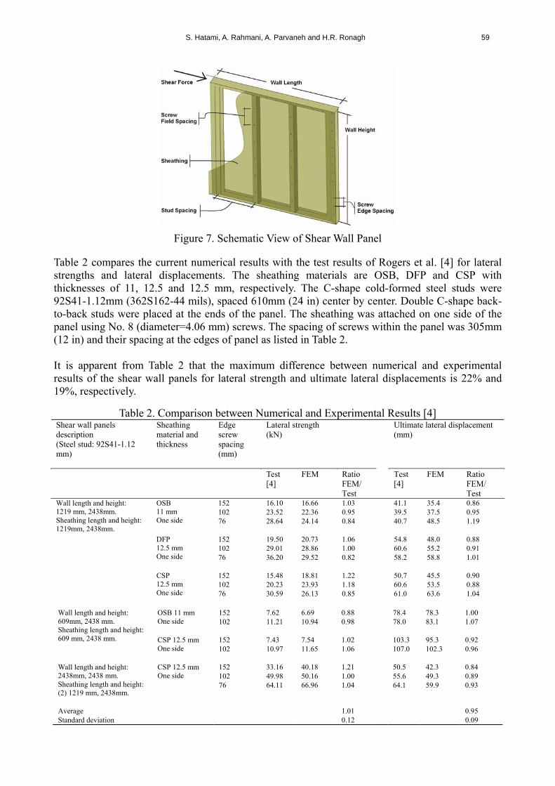
4. VERIFICATION OF THE SHEAR WALL MODEL In order to evaluate the system behavior, a push-over analysis with geometry and material nonlinearity was performed on different specimens. For this purpose, it was necessary to consider different drifts on the wall and record the corresponding lateral force. This procedure had to be continued until the structure reached its maximum lateral strength for a certain drift. In this section, the results of these analyses are compared with the experimental results of other researchers. Comparison of the experimental and FEM results for shear wall panels are presented in Table 2 through 4. Moreover, in order to have a better understanding, the ratios of the finite element results to the test results are included. The experimental results of references [1,2,3,4,5] are used to validate the accuracy of the presented numerical method. For the purpose of the analyses, the geometric gross properties of the steel studs were determined on the basis of cross-sectional dimensions presented in the literature. Unless specified differently for individual cases, the yield strength, Young’s modulus and Poisson's ratio of steel are considered to be 230 MPa, 203 GPa and 0.3 respectively. The standard nomenclature including member size (both depth and flange width), style, and material thickness is used to introduce frame members. For example 92S41-1.12mm introduce a stud with 92 mm depth, 41 mm flange width and 1.12 mm material thickness. The following material properties for the sheathing material are also utilized in the study: the modulus of elasticity for OSB, DFP and CSP are 9917 [10], 10,445 and 7376MPa [11], respectively. For gypsum wall board (GWB), the modulus of elasticity is 1290MPa [12]. A schematic view of a studied shear wall panel is illustrated in Figure 7.
S. Hatami, A. Rahmani, A. Parvaneh and H.R. Ronagh 59
Figure 7. Schematic View of Shear Wall Panel
Table 2 compares the current numerical results with the test results of Rogers et al. [4] for lateral strengths and lateral displacements. The sheathing materials are OSB, DFP and CSP with thicknesses of 11, 12.5 and 12.5 mm, respectively. The C-shape cold-formed steel studs were 92S41-1.12mm (362S162-44 mils), spaced 610mm (24 in) center by center. Double C-shape back-to-back studs were placed at the ends of the panel. The sheathing was attached on one side of the panel using No. 8 (diameter=4.06 mm) screws. The spacing of screws within the panel was 305mm (12 in) and their spacing at the edges of panel as listed in Table 2. It is apparent from Table 2 that the maximum difference between numerical and experimental results of the shear wall panels for lateral strength and ultimate lateral displacements is 22% and 19%, respectively.
Table 2. Comparison between Numerical and Experimental Results [4] Shear wall panels description (Steel stud: 92S41-1.12 mm)
Sheathing material and thickness
Edge screw spacing (mm)
Lateral strength (kN)
Ultimate lateral displacement (mm)
Test [4]
FEM Ratio FEM/ Test
Test [4]
FEM Ratio FEM/ Test
152 16.10 16.66 1.03 41.1 35.4 0.86 102 23.52 22.36 0.95 39.5 37.5 0.95
OSB 11 mm One side 76 28.64 24.14 0.84 40.7 48.5 1.19
152 19.50 20.73 1.06 54.8 48.0 0.88 102 29.01 28.86 1.00 60.6 55.2 0.91
DFP 12.5 mm One side 76 36.20 29.52 0.82 58.2 58.8 1.01
152 15.48 18.81 1.22 50.7 45.5 0.90 102 20.23 23.93 1.18 60.6 53.5 0.88
Wall length and height: 1219 mm, 2438mm. Sheathing length and height: 1219mm, 2438mm.
CSP 12.5 mm One side 76 30.59 26.13 0.85 61.0 63.6 1.04
152 7.62 6.69 0.88 78.4 78.3 1.00 OSB 11 mm
One side 102 11.21 10.94 0.98 78.0 83.1 1.07
152 7.43 7.54 1.02 103.3 95.3 0.92
Wall length and height: 609mm, 2438 mm. Sheathing length and height: 609 mm, 2438 mm. CSP 12.5 mm
One side 102 10.97 11.65 1.06 107.0 102.3 0.96
152 33.16 40.18 1.21 50.5 42.3 0.84 CSP 12.5 mm One side 102 49.98 50.16 1.00 55.6 49.3 0.89
Wall length and height: 2438mm, 2438 mm. Sheathing length and height: (2) 1219 mm, 2438mm.
76 64.11 66.96 1.04 64.1 59.9 0.93
Average 1.01 0.95 Standard deviation 0.12 0.09
60 A Parametric Study on Seismic Characteristics of Cold-Formed Steel Shear Walls by Finite Element Modeling
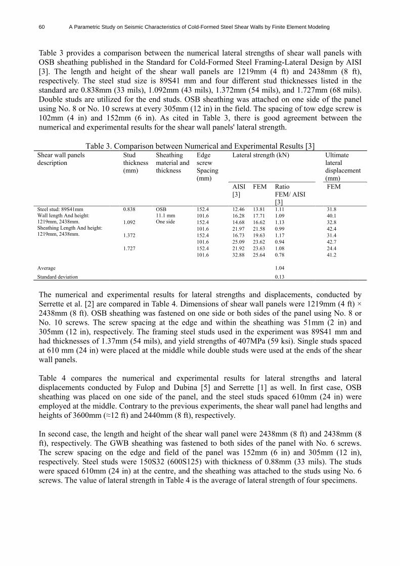
Table 3 provides a comparison between the numerical lateral strengths of shear wall panels with OSB sheathing published in the Standard for Cold-Formed Steel Framing-Lateral Design by AISI [3]. The length and height of the shear wall panels are 1219mm (4 ft) and 2438mm (8 ft), respectively. The steel stud size is 89S41 mm and four different stud thicknesses listed in the standard are 0.838mm (33 mils), 1.092mm (43 mils), 1.372mm (54 mils), and 1.727mm (68 mils). Double studs are utilized for the end studs. OSB sheathing was attached on one side of the panel using No. 8 or No. 10 screws at every 305mm (12 in) in the field. The spacing of tow edge screw is 102mm (4 in) and 152mm (6 in). As cited in Table 3, there is good agreement between the numerical and experimental results for the shear wall panels' lateral strength.
Table 3. Comparison between Numerical and Experimental Results [3] Shear wall panels description
Stud thickness (mm)
Sheathing material and thickness
Edge screw Spacing (mm)
Lateral strength (kN) Ultimate lateral displacement (mm)
AISI [3]
FEM Ratio FEM/ AISI [3]
FEM
152.4 12.46 13.81 1.11 31.8 0.838 101.6 16.28 17.71 1.09 40.1 152.4 14.68 16.62 1.13 32.8 1.092
OSB 11.1 mm One side
101.6 21.97 21.58 0.99 42.4 152.4 16.73 19.63 1.17 31.4
1.372 101.6 25.09 23.62 0.94 42.7 152.4 21.92 23.63 1.08 24.4
Steel stud: 89S41mm Wall length And height: 1219mm, 2438mm. Sheathing Length And height: 1219mm, 2438mm.
1.727 101.6 32.88 25.64 0.78 41.2
Average 1.04
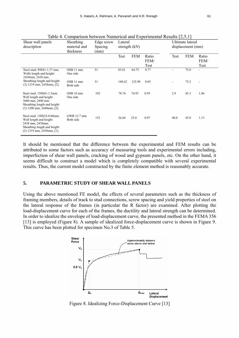
Standard deviation 0.13 The numerical and experimental results for lateral strengths and displacements, conducted by Serrette et al. [2] are compared in Table 4. Dimensions of shear wall panels were 1219mm (4 ft) × 2438mm (8 ft). OSB sheathing was fastened on one side or both sides of the panel using No. 8 or No. 10 screws. The screw spacing at the edge and within the sheathing was 51mm (2 in) and 305mm (12 in), respectively. The framing steel studs used in the experiment was 89S41 mm and had thicknesses of 1.37mm (54 mils), and yield strengths of 407MPa (59 ksi). Single studs spaced at 610 mm (24 in) were placed at the middle while double studs were used at the ends of the shear wall panels. Table 4 compares the numerical and experimental results for lateral strengths and lateral displacements conducted by Fulop and Dubina [5] and Serrette [1] as well. In first case, OSB sheathing was placed on one side of the panel, and the steel studs spaced 610mm (24 in) were employed at the middle. Contrary to the previous experiments, the shear wall panel had lengths and heights of 3600mm (≈12 ft) and 2440mm (8 ft), respectively. In second case, the length and height of the shear wall panel were 2438mm (8 ft) and 2438mm (8 ft), respectively. The GWB sheathing was fastened to both sides of the panel with No. 6 screws. The screw spacing on the edge and field of the panel was 152mm (6 in) and 305mm (12 in), respectively. Steel studs were 150S32 (600S125) with thickness of 0.88mm (33 mils). The studs were spaced 610mm (24 in) at the centre, and the sheathing was attached to the studs using No. 6 screws. The value of lateral strength in Table 4 is the average of lateral strength of four specimens.
S. Hatami, A. Rahmani, A. Parvaneh and H.R. Ronagh 61
Table 4. Comparison between Numerical and Experimental Results [2,5,1]
Shear wall panels description
Sheathing material and thickness
Edge screw Spacing (mm)
Lateral strength (kN)
Ultimate lateral displacement (mm)
Test FEM Ratio FEM/ Test
Test FEM Ratio FEM/ Test
OSB 11 mm One side
51 83.81 64.75 0.77 - 75.0 -
Steel stud: 89S41-1.37 mm. Walls length and height: 2438mm, 2438 mm. Sheathing length and height: (2) 1219 mm, 2438mm, [2].
OSB 11 mm Both side
51 148.62 125.98 0.85
- 75.2 -
OSB 10 mm One side
102 78.76 74.93 0.95 2.9 45.3 1.06 Steel stud: 150S41-1.5mm. Wall length and height: 3600 mm, 2440 mm. Sheathing length and height: (3) 1200 mm, 2440mm, [5].
GWB 12.7 mm Both side
152 26.64 25.8 0.97 40.0 45.0 1.13
Steel stud: 150S32-0.88mm. Wall length and height: 2438 mm, 2438mm. Sheathing length and height: (2) 1219 mm, 2438mm, [1].
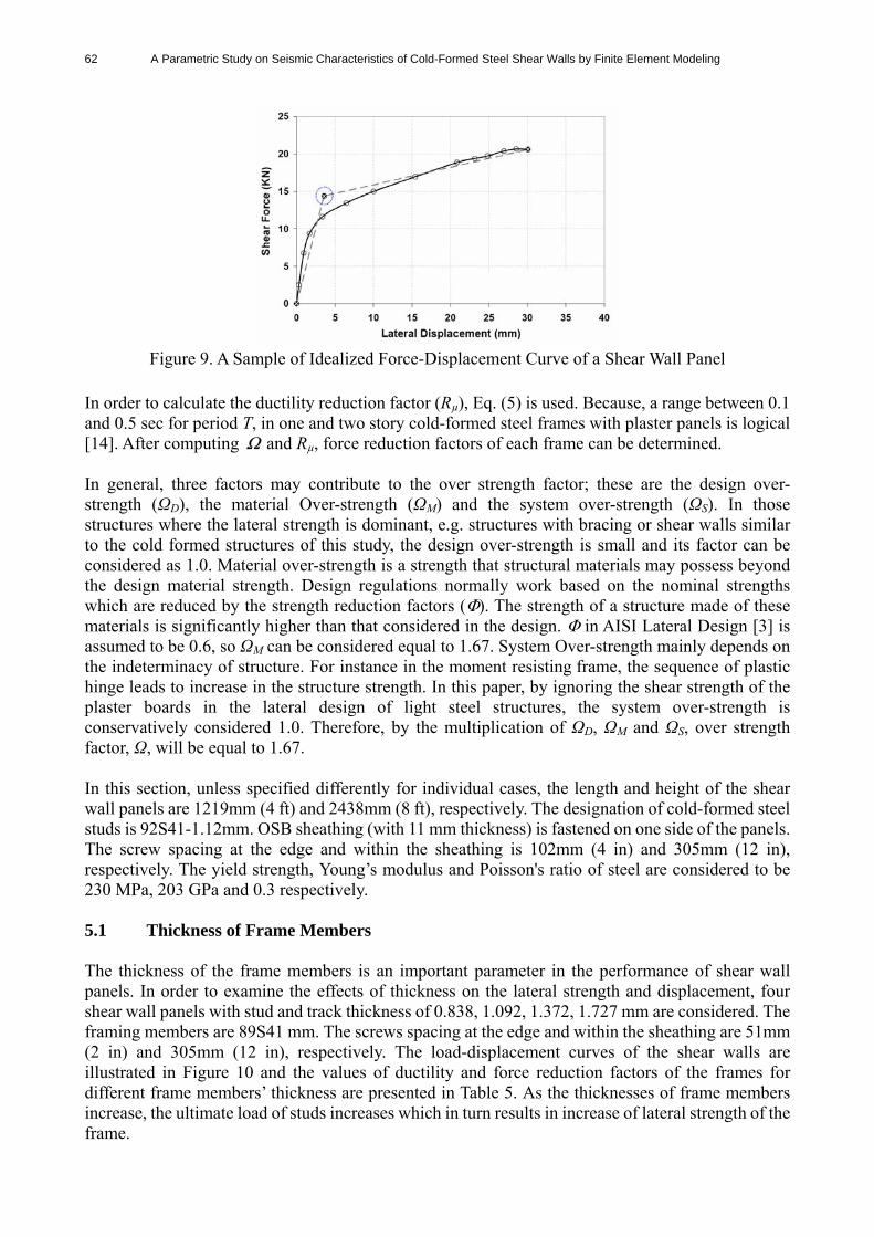
It should be mentioned that the difference between the experimental and FEM results can be attributed to some factors such as accuracy of measuring tools and experimental errors including, imperfection of shear wall panels, cracking of wood and gypsum panels, etc. On the other hand, it seems difficult to construct a model which is completely compatible with several experimental results. Thus, the current model constructed by the finite element method is reasonably accurate. 5. PARAMETRIC STUDY OF SHEAR WALL PANELS Using the above mentioned FE model, the effects of several parameters such as the thickness of framing members, details of track to stud connections, screw spacing and yield properties of steel on the lateral response of the frames (in particular the R factor) are examined. After plotting the load-displacement curve for each of the frames, the ductility and lateral strength can be determined. In order to idealize the envelope of load-displacement curve, the presented method in the FEMA 356 [13] is employed (Figure 8). A sample of idealized force-displacement curve is shown in Figure 9. This curve has been plotted for specimen No.3 of Table 5.
Figure 8. Idealizing Force-Displacement Curve [13]
62 A Parametric Study on Seismic Characteristics of Cold-Formed Steel Shear Walls by Finite Element Modeling
Figure 9. A Sample of Idealized Force-Displacement Curve of a Shear Wall Panel
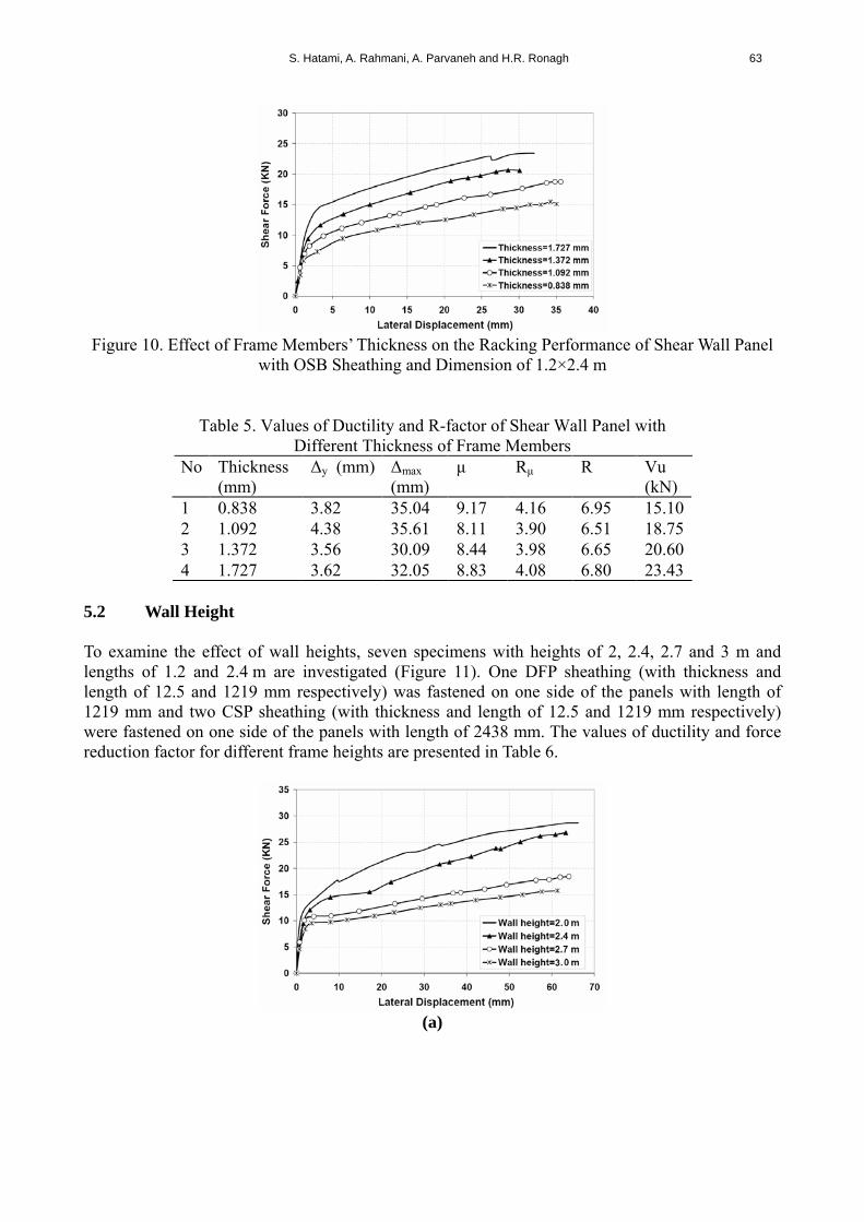
In order to calculate the ductility reduction factor (Rµ), Eq. (5) is used. Because, a range between 0.1 and 0.5 sec for period T, in one and two story cold-formed steel frames with plaster panels is logical [14]. After computing Ω and Rµ, force reduction factors of each frame can be determined. In general, three factors may contribute to the over strength factor; these are the design over-strength (ΩD), the material Over-strength (ΩM) and the system over-strength (ΩS). In those structures where the lateral strength is dominant, e.g. structures with bracing or shear walls similar to the cold formed structures of this study, the design over-strength is small and its factor can be considered as 1.0. Material over-strength is a strength that structural materials may possess beyond the design material strength. Design regulations normally work based on the nominal strengths which are reduced by the strength reduction factors (Φ). The strength of a structure made of these materials is significantly higher than that considered in the design. Φ in AISI Lateral Design [3] is assumed to be 0.6, so ΩM can be considered equal to 1.67. System Over-strength mainly depends on the indeterminacy of structure. For instance in the moment resisting frame, the sequence of plastic hinge leads to increase in the structure strength. In this paper, by ignoring the shear strength of the plaster boards in the lateral design of light steel structures, the system over-strength is conservatively considered 1.0. Therefore, by the multiplication of ΩD, ΩM and ΩS, over strength factor, Ω, will be equal to 1.67. In this section, unless specified differently for individual cases, the length and height of the shear wall panels are 1219mm (4 ft) and 2438mm (8 ft), respectively. The designation of cold-formed steel studs is 92S41-1.12mm. OSB sheathing (with 11 mm thickness) is fastened on one side of the panels. The screw spacing at the edge and within the sheathing is 102mm (4 in) and 305mm (12 in), respectively. The yield strength, Young’s modulus and Poisson's ratio of steel are considered to be 230 MPa, 203 GPa and 0.3 respectively. 5.1 Thickness of Frame Members The thickness of the frame members is an important parameter in the performance of shear wall panels. In order to examine the effects of thickness on the lateral strength and displacement, four shear wall panels with stud and track thickness of 0.838, 1.092, 1.372, 1.727 mm are considered. The framing members are 89S41 mm. The screws spacing at the edge and within the sheathing are 51mm (2 in) and 305mm (12 in), respectively. The load-displacement curves of the shear walls are illustrated in Figure 10 and the values of ductility and force reduction factors of the frames for different frame members’ thickness are presented in Table 5. As the thicknesses of frame members increase, the ultimate load of studs increases which in turn results in increase of lateral strength of the frame.
S. Hatami, A. Rahmani, A. Parvaneh and H.R. Ronagh 63
Figure 10. Effect of Frame Members’ Thickness on the Racking Performance of Shear Wall Panel
with OSB Sheathing and Dimension of 1.2×2.4 m
Table 5. Values of Ductility and R-factor of Shear Wall Panel with Different Thickness of Frame Members
No Thickness (mm)
Δy (mm) Δmax (mm)
μ Rμ R Vu (kN)
1 0.838 3.82 35.04 9.17 4.16 6.95 15.10 2 1.092 4.38 35.61 8.11 3.90 6.51 18.75 3 1.372 3.56 30.09 8.44 3.98 6.65 20.60 4 1.727 3.62 32.05 8.83 4.08 6.80 23.43
5.2 Wall Height To examine the effect of wall heights, seven specimens with heights of 2, 2.4, 2.7 and 3 m and lengths of 1.2 and 2.4 m are investigated (Figure 11). One DFP sheathing (with thickness and length of 12.5 and 1219 mm respectively) was fastened on one side of the panels with length of 1219 mm and two CSP sheathing (with thickness and length of 12.5 and 1219 mm respectively) were fastened on one side of the panels with length of 2438 mm. The values of ductility and force reduction factor for different frame heights are presented in Table 6.
(a)
64 A Parametric Study on Seismic Characteristics of Cold-Formed Steel Shear Walls by Finite Element Modeling
(b)
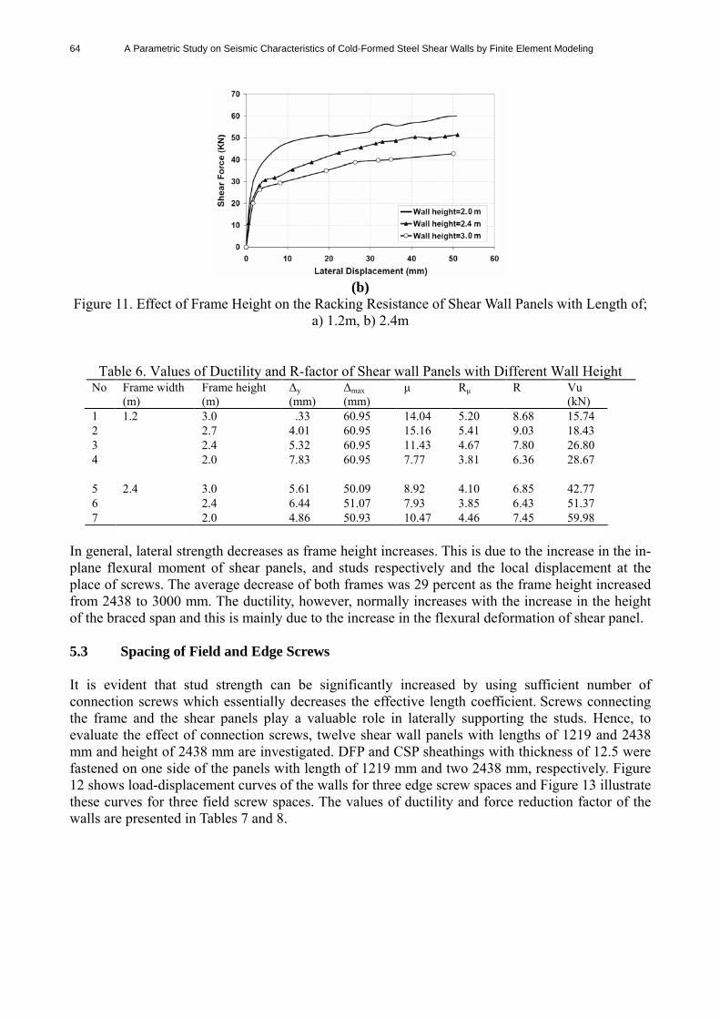
Figure 11. Effect of Frame Height on the Racking Resistance of Shear Wall Panels with Length of; a) 1.2m, b) 2.4m
Table 6. Values of Ductility and R-factor of Shear wall Panels with Different Wall Height No Frame width
(m) Frame height (m)
Δy (mm)
Δmax (mm)
μ Rμ R Vu (kN)
1 3.0 .33 60.95 14.04 5.20 8.68 15.74 2 2.7 4.01 60.95 15.16 5.41 9.03 18.43 3 2.4 5.32 60.95 11.43 4.67 7.80 26.80 4
1.2
2.0 7.83 60.95 7.77 3.81 6.36 28.67
5 3.0 5.61 50.09 8.92 4.10 6.85 42.77 6 2.4 6.44 51.07 7.93 3.85 6.43 51.37 7
2.4
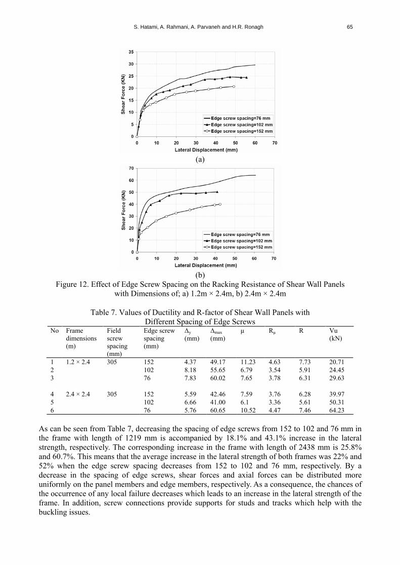
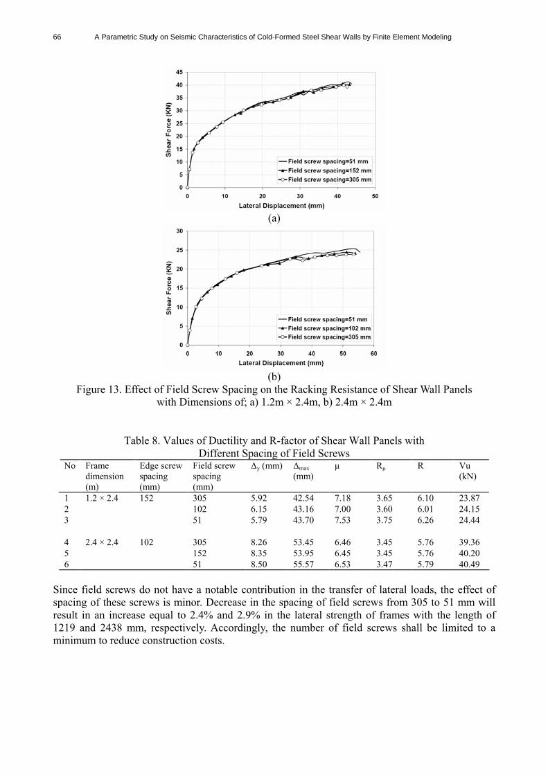
2.0 4.86 50.93 10.47 4.46 7.45 59.98 In general, lateral strength decreases as frame height increases. This is due to the increase in the in-plane flexural moment of shear panels, and studs respectively and the local displacement at the place of screws. The average decrease of both frames was 29 percent as the frame height increased from 2438 to 3000 mm. The ductility, however, normally increases with the increase in the height of the braced span and this is mainly due to the increase in the flexural deformation of shear panel. 5.3 Spacing of Field and Edge Screws It is evident that stud strength can be significantly increased by using sufficient number of connection screws which essentially decreases the effective length coefficient. Screws connecting the frame and the shear panels play a valuable role in laterally supporting the studs. Hence, to evaluate the effect of connection screws, twelve shear wall panels with lengths of 1219 and 2438 mm and height of 2438 mm are investigated. DFP and CSP sheathings with thickness of 12.5 were fastened on one side of the panels with length of 1219 mm and two 2438 mm, respectively. Figure 12 shows load-displacement curves of the walls for three edge screw spaces and Figure 13 illustrate these curves for three field screw spaces. The values of ductility and force reduction factor of the walls are presented in Tables 7 and 8.
S. Hatami, A. Rahmani, A. Parvaneh and H.R. Ronagh 65
(a)
(b)
Figure 12. Effect of Edge Screw Spacing on the Racking Resistance of Shear Wall Panels with Dimensions of; a) 1.2m × 2.4m, b) 2.4m × 2.4m
Table 7. Values of Ductility and R-factor of Shear Wall Panels with
Different Spacing of Edge Screws No Frame
dimensions (m)
Field screw spacing (mm)
Edge screw spacing (mm)
Δy (mm)
Δmax (mm)
μ Rμ R Vu (kN)
1 305 152 4.37 49.17 11.23 4.63 7.73 20.71 2 102 8.18 55.65 6.79 3.54 5.91 24.45 3
1.2 × 2.4
76 7.83 60.02 7.65 3.78 6.31 29.63 4 305 152 5.59 42.46 7.59 3.76 6.28 39.97 5 102 6.66 41.00 6.1 3.36 5.61 50.31 6
2.4 × 2.4
76 5.76 60.65 10.52 4.47 7.46 64.23
As can be seen from Table 7, decreasing the spacing of edge screws from 152 to 102 and 76 mm in the frame with length of 1219 mm is accompanied by 18.1% and 43.1% increase in the lateral strength, respectively. The corresponding increase in the frame with length of 2438 mm is 25.8% and 60.7%. This means that the average increase in the lateral strength of both frames was 22% and 52% when the edge screw spacing decreases from 152 to 102 and 76 mm, respectively. By a decrease in the spacing of edge screws, shear forces and axial forces can be distributed more uniformly on the panel members and edge members, respectively. As a consequence, the chances of the occurrence of any local failure decreases which leads to an increase in the lateral strength of the frame. In addition, screw connections provide supports for studs and tracks which help with the buckling issues.
66 A Parametric Study on Seismic Characteristics of Cold-Formed Steel Shear Walls by Finite Element Modeling
(a)
(b)
Figure 13. Effect of Field Screw Spacing on the Racking Resistance of Shear Wall Panels with Dimensions of; a) 1.2m × 2.4m, b) 2.4m × 2.4m
Table 8. Values of Ductility and R-factor of Shear Wall Panels with Different Spacing of Field Screws
No Frame dimension (m)
Edge screw spacing (mm)
Field screw spacing (mm)
Δy (mm) Δmax (mm)
μ Rμ R Vu (kN)
1 152 305 5.92 42.54 7.18 3.65 6.10 23.87 2 102 6.15 43.16 7.00 3.60 6.01 24.15 3
1.2 × 2.4
51 5.79 43.70 7.53 3.75 6.26 24.44 4 102 305 8.26 53.45 6.46 3.45 5.76 39.36 5 152 8.35 53.95 6.45 3.45 5.76 40.20 6
2.4 × 2.4
51 8.50 55.57 6.53 3.47 5.79 40.49 Since field screws do not have a notable contribution in the transfer of lateral loads, the effect of spacing of these screws is minor. Decrease in the spacing of field screws from 305 to 51 mm will result in an increase equal to 2.4% and 2.9% in the lateral strength of frames with the length of 1219 and 2438 mm, respectively. Accordingly, the number of field screws shall be limited to a minimum to reduce construction costs.
S. Hatami, A. Rahmani, A. Parvaneh and H.R. Ronagh 67
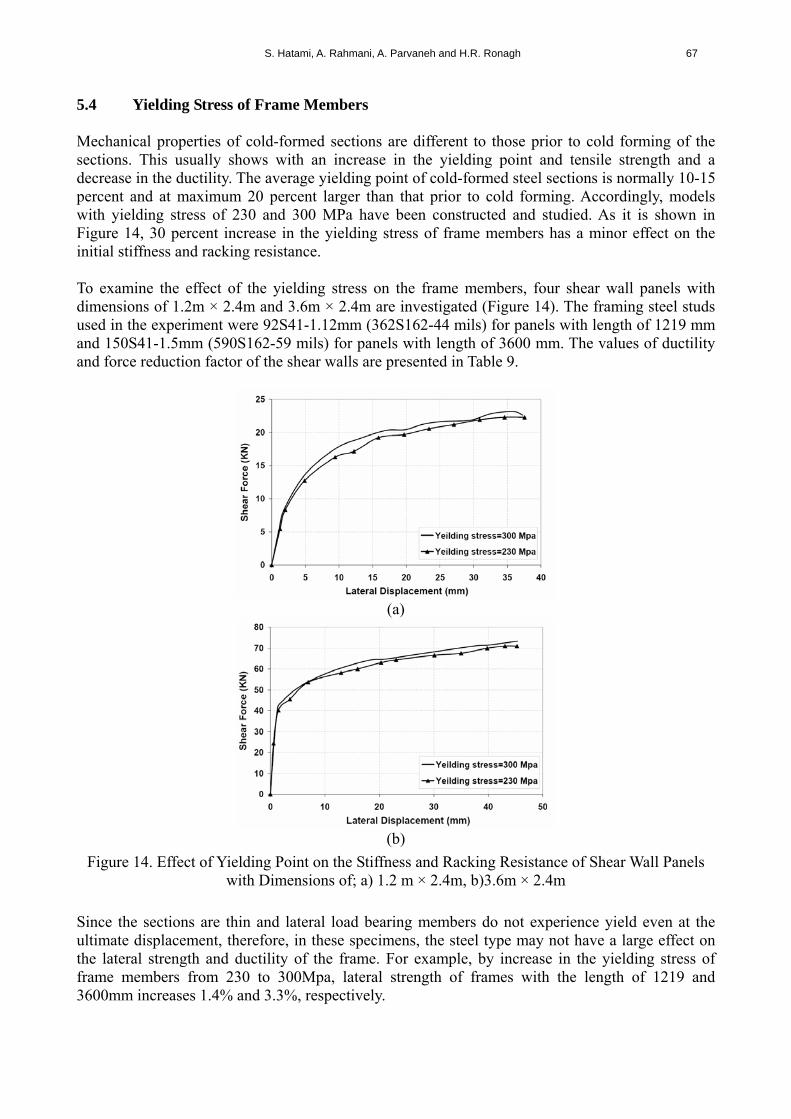
5.4 Yielding Stress of Frame Members Mechanical properties of cold-formed sections are different to those prior to cold forming of the sections. This usually shows with an increase in the yielding point and tensile strength and a decrease in the ductility. The average yielding point of cold-formed steel sections is normally 10-15 percent and at maximum 20 percent larger than that prior to cold forming. Accordingly, models with yielding stress of 230 and 300 MPa have been constructed and studied. As it is shown in Figure 14, 30 percent increase in the yielding stress of frame members has a minor effect on the initial stiffness and racking resistance. To examine the effect of the yielding stress on the frame members, four shear wall panels with dimensions of 1.2m × 2.4m and 3.6m × 2.4m are investigated (Figure 14). The framing steel studs used in the experiment were 92S41-1.12mm (362S162-44 mils) for panels with length of 1219 mm and 150S41-1.5mm (590S162-59 mils) for panels with length of 3600 mm. The values of ductility and force reduction factor of the shear walls are presented in Table 9.
(a)
(b)
Figure 14. Effect of Yielding Point on the Stiffness and Racking Resistance of Shear Wall Panels with Dimensions of; a) 1.2 m × 2.4m, b)3.6m × 2.4m
Since the sections are thin and lateral load bearing members do not experience yield even at the ultimate displacement, therefore, in these specimens, the steel type may not have a large effect on the lateral strength and ductility of the frame. For example, by increase in the yielding stress of frame members from 230 to 300Mpa, lateral strength of frames with the length of 1219 and 3600mm increases 1.4% and 3.3%, respectively.
68 A Parametric Study on Seismic Characteristics of Cold-Formed Steel Shear Walls by Finite Element Modeling
Table 9. Values of Ductility and R-factor of Shear Wall Panels with Different Yielding Stress of Frame Members
No Frame dimension (m)
Yielding stress (MPa)
Δy (mm)
Δmax (mm)
μ Rμ R Vu (kN)
1 230 6.15 37.55 6.09 3.34 5.58 22.29 2
1.2 × 2.4 300 6.15 37.31 6.06 3.33 5.56 22.60
3 230 4.34 45.26 10.41 4.45 7.43 70.92 4
3.6 × 2.4 300 3.59 45.35 12.61 4.92 8.22 73.27
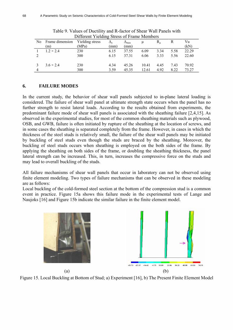
6. FAILURE MODES In the current study, the behavior of shear wall panels subjected to in-plane lateral loading is considered. The failure of shear wall panel at ultimate strength state occurs when the panel has no further strength to resist lateral loads. According to the results obtained from experiments, the predominant failure mode of shear wall panels is associated with the sheathing failure [2,4,15]. As observed in the experimental studies, for most of the common sheathing materials such as plywood, OSB, and GWB, failure is often initiated by rupture of the sheathing at the location of screws, and in some cases the sheathing is separated completely from the frame. However, in cases in which the thickness of the steel studs is relatively small, the failure of the shear wall panels may be initiated by buckling of steel studs even though the studs are braced by the sheathing. Moreover, the buckling of steel studs occurs when sheathing is employed on the both sides of the frame. By applying the sheathing on both sides of the frame, or doubling the sheathing thickness, the panel lateral strength can be increased. This, in turn, increases the compressive force on the studs and may lead to overall buckling of the studs. All failure mechanisms of shear wall panels that occur in laboratory can not be observed using finite element modeling. Two types of failure mechanisms that can be observed in these modeling are as follows: Local buckling of the cold-formed steel section at the bottom of the compression stud is a common event in practice. Figure 15a shows this failure mode in the experimental tests of Lange and Naujoks [16] and Figure 15b indicate the similar failure in the finite element model.
(a) (b)
Figure 15. Local Buckling at Bottom of Stud; a) Experiment [16], b) The Present Finite Element Model
S. Hatami, A. Rahmani, A. Parvaneh and H.R. Ronagh 69
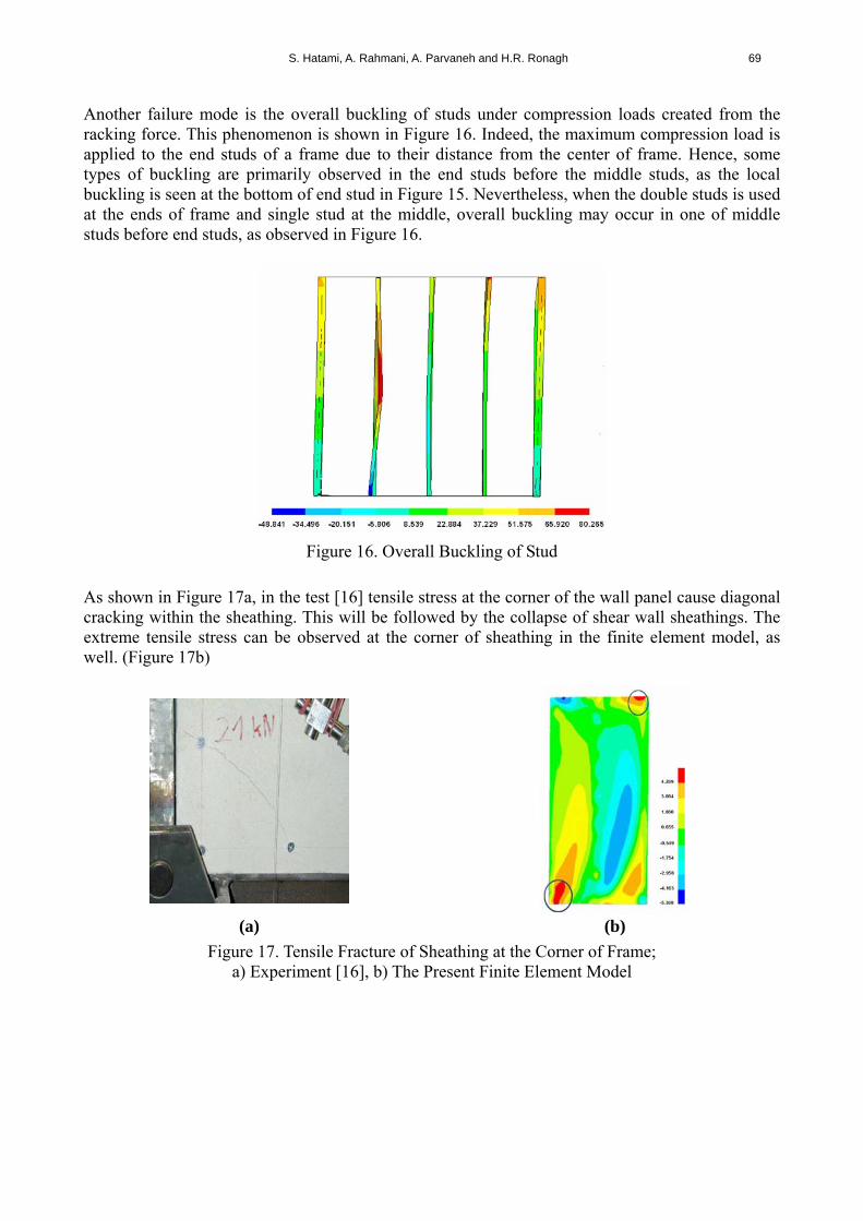
Another failure mode is the overall buckling of studs under compression loads created from the racking force. This phenomenon is shown in Figure 16. Indeed, the maximum compression load is applied to the end studs of a frame due to their distance from the center of frame. Hence, some types of buckling are primarily observed in the end studs before the middle studs, as the local buckling is seen at the bottom of end stud in Figure 15. Nevertheless, when the double studs is used at the ends of frame and single stud at the middle, overall buckling may occur in one of middle studs before end studs, as observed in Figure 16.
Figure 16. Overall Buckling of Stud
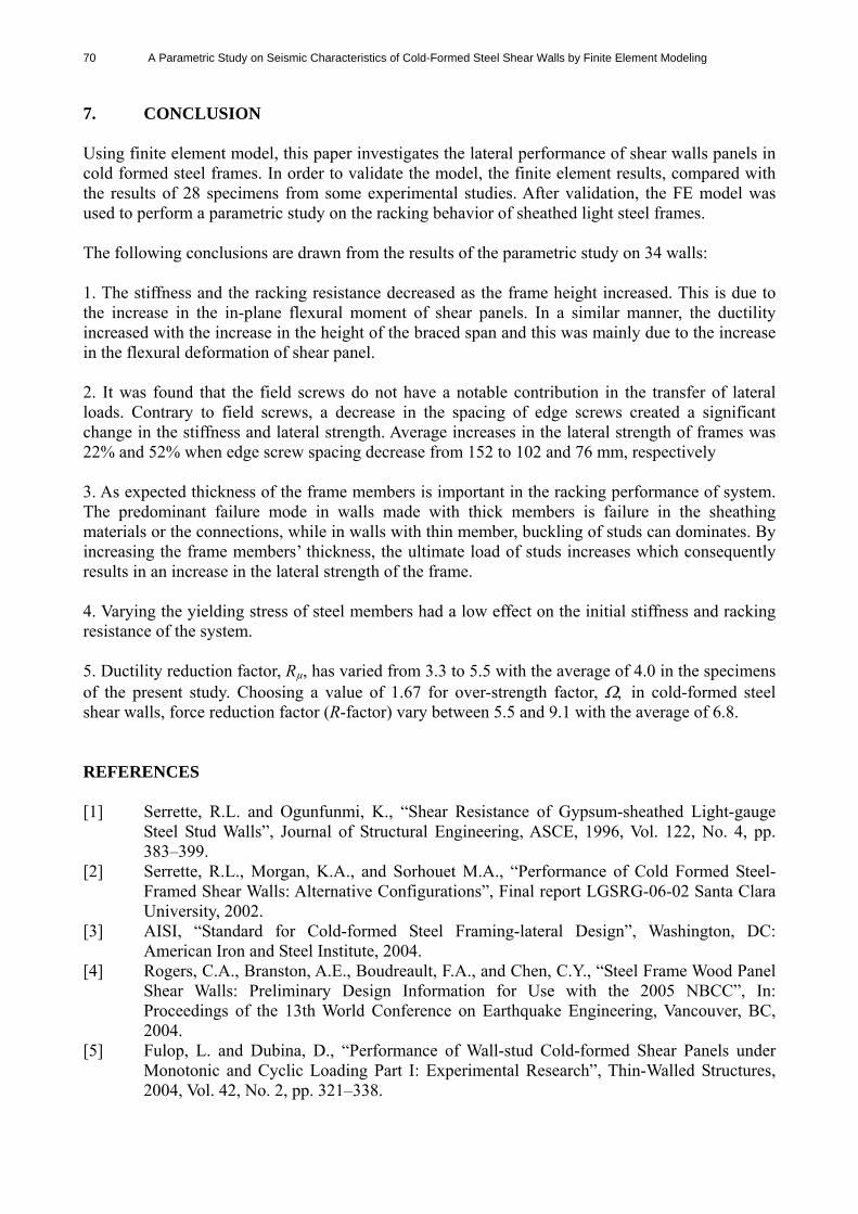
As shown in Figure 17a, in the test [16] tensile stress at the corner of the wall panel cause diagonal cracking within the sheathing. This will be followed by the collapse of shear wall sheathings. The extreme tensile stress can be observed at the corner of sheathing in the finite element model, as well. (Figure 17b)
(a) (b)
Figure 17. Tensile Fracture of Sheathing at the Corner of Frame; a) Experiment [16], b) The Present Finite Element Model
70 A Parametric Study on Seismic Characteristics of Cold-Formed Steel Shear Walls by Finite Element Modeling
7. CONCLUSION Using finite element model, this paper investigates the lateral performance of shear walls panels in cold formed steel frames. In order to validate the model, the finite element results, compared with the results of 28 specimens from some experimental studies. After validation, the FE model was used to perform a parametric study on the racking behavior of sheathed light steel frames. The following conclusions are drawn from the results of the parametric study on 34 walls: 1. The stiffness and the racking resistance decreased as the frame height increased. This is due to the increase in the in-plane flexural moment of shear panels. In a similar manner, the ductility increased with the increase in the height of the braced span and this was mainly due to the increase in the flexural deformation of shear panel. 2. It was found that the field screws do not have a notable contribution in the transfer of lateral loads. Contrary to field screws, a decrease in the spacing of edge screws created a significant change in the stiffness and lateral strength. Average increases in the lateral strength of frames was 22% and 52% when edge screw spacing decrease from 152 to 102 and 76 mm, respectively 3. As expected thickness of the frame members is important in the racking performance of system. The predominant failure mode in walls made with thick members is failure in the sheathing materials or the connections, while in walls with thin member, buckling of studs can dominates. By increasing the frame members’ thickness, the ultimate load of studs increases which consequently results in an increase in the lateral strength of the frame. 4. Varying the yielding stress of steel members had a low effect on the initial stiffness and racking resistance of the system. 5. Ductility reduction factor, Rµ, has varied from 3.3 to 5.5 with the average of 4.0 in the specimens of the present study. Choosing a value of 1.67 for over-strength factor, in cold-formed steel shear walls, force reduction factor (R-factor) vary between 5.5 and 9.1 with the average of 6.8. REFERENCES [1] Serrette, R.L. and Ogunfunmi, K., “Shear Resistance of Gypsum-sheathed Light-gauge
Steel Stud Walls”, Journal of Structural Engineering, ASCE, 1996, Vol. 122, No. 4, pp. 383–399.
[2] Serrette, R.L., Morgan, K.A., and Sorhouet M.A., “Performance of Cold Formed Steel-Framed Shear Walls: Alternative Configurations”, Final report LGSRG-06-02 Santa Clara University, 2002.
[3] AISI, “Standard for Cold-formed Steel Framing-lateral Design”, Washington, DC: American Iron and Steel Institute, 2004.
[4] Rogers, C.A., Branston, A.E., Boudreault, F.A., and Chen, C.Y., “Steel Frame Wood Panel Shear Walls: Preliminary Design Information for Use with the 2005 NBCC”, In: Proceedings of the 13th World Conference on Earthquake Engineering, Vancouver, BC, 2004.
[5] Fulop, L. and Dubina, D., “Performance of Wall-stud Cold-formed Shear Panels under Monotonic and Cyclic Loading Part I: Experimental Research”, Thin-Walled Structures, 2004, Vol. 42, No. 2, pp. 321–338.
S. Hatami, A. Rahmani, A. Parvaneh and H.R. Ronagh 71
[6] Fulop, L. and Dubina, D., “Performance of Wall-stud Cold-formed Shear Panels under Monotonic and Cyclic Loading Part II: Numerical Modeling and Performance Analysis”, Thin-Walled Structures, 2004, Vol. 42, No. 2, pp. 339–349.
[7] Xu, L. and Martinez, J., “Strength and Stiffness Determination of Shear Wall Panels in Cold Formed Steel Framing”, Thin-Walled Structures, 2006, Vol. 44, No. 10, pp. 1084–1095.
[8] Pan, C.L. and Shan, M.Y., “Monotonic Shear Tests of Cold-formed Steel Wall Frames with Sheathing”, Thin-Walled Structures, 2011, Vol. 49, No. 2, pp. 363-370.
[9] Newmark, N.M. and Hall, W.J., “Earthquake Spectra and Design”, Engineering Monograph, Earthquake Engineering Research Institute, Berkeley, California, 1982.
[10] OSB Design Manual, “Design Rated Oriented Strand Board”, Willowdale, ON: Structural Board Association, 1995.
[11] CANPLY, “Plywood Design Fundamentals”, Vancouver, BC: Canadian Plywood Association, 2003.
[12] Gypsum, “Association Gypsum Board Typical Mechanical and Physical Properties”, Report GA-235-01, Washington, DC, 2002.
[13] FEMA 356, “Prestandard and Commentary for the Seismic Rehabilitation of Buildings, 2000 edition”, Washington (DC, USA): Building Seismic Safety Council, National Institute of Building Science, 2000.
[14] Gad, E.F., Chandler, A.M., Duffield, C.F., and Hutchinson, G.L., “Earthquake Ductility and Over Strength in Residential Structures”, Structural Engineering and Mechanics, 1999, Vol. 8, No. 4, pp. 361-382.
[15] Gad, E.F., Chandler, A.M., Duffield, C.F., and Stark, G., “Lateral Behaviour of Plasterboard-Clad Residential Steel Frames”, Journal of Structural Engineering, ASCE, January 1999, Vol. 125, No. 1, pp. 32–39.
[16] Lange, J. and Naujoks, B., “Behaviour of Cold-formed Steel Shear Walls under Horizontal and Vertical Loads”, Thin-Walled Structures, 2006, Vol. 44, No. 12, pp. 1214–1222.