Embed Size (px)
Citation preview

This is a repository copy of A Particle Element Approach for Modelling the 3D Printing Process of Fibre Reinforced Polymer Composites.
White Rose Research Online URL for this paper:http://eprints.whiterose.ac.uk/121170/
Version: Published Version
Article:
Yang, D, Wu, K, Wan, L et al. (1 more author) (2017) A Particle Element Approach for Modelling the 3D Printing Process of Fibre Reinforced Polymer Composites. Journal of Manufacturing and Materials Processing, 1 (1). 10. ISSN 2504-4494
https://doi.org/10.3390/jmmp1010010
[email protected]://eprints.whiterose.ac.uk/
Reuse
Items deposited in White Rose Research Online are protected by copyright, with all rights reserved unless indicated otherwise. They may be downloaded and/or printed for private study, or other acts as permitted by national copyright laws. The publisher or other rights holders may allow further reproduction and re-use of the full text version. This is indicated by the licence information on the White Rose Research Online record for the item.
Takedown
If you consider content in White Rose Research Online to be in breach of UK law, please notify us by emailing [email protected] including the URL of the record and the reason for the withdrawal request.
Manufacturing andMaterials Processing
Journal of
Article
A Particle Element Approach for Modellingthe 3D Printing Process of Fibre ReinforcedPolymer Composites
Dongmin Yang *, Ke Wu, Lei Wan ID and Yong Sheng
School of Civil Engineering, University of Leeds, Leeds LS2 9JT, UK; [email protected] (K.W.);
[email protected] (L.W.); [email protected] (Y.S.)
* Correspondence: [email protected]; Tel.: +44-(0)113-343-2291
Received: 4 August 2017; Accepted: 2 September 2017; Published: 8 September 2017
Abstract: This paper presents a new numerical approach for modelling the 3D printing process of
fibre reinforced polymer composites by fused deposition modelling (FDM). The approach is based on
the coupling between two particle methods, namely smoothed particle hydrodynamics (SPH) and
discrete element method (DEM). The coupled SPH-DEM model has distinctive advantages in dealing
with the free surface flow, large deformation of fibres, and/or fibre-fibre interaction that are involved
in the FDM process. A numerical feasibility study is carried out to demonstrate its capability for
both short and continuous fibre reinforced polymer composites, with promising results achieved for
the rheological flow and fibre orientation and deformation.
Keywords: fibre reinforced polymer composites; 3D printing; fused deposition modelling; smoothed
particle hydrodynamics; discrete element method
1. Introduction
Fibre-reinforced polymer (FRP) composites are extensively used in lightweight constructions
in the aerospace, automotive, infrastructure, energy, and sports sectors. Commercially used FRPs
are mainly based on the use of thermosetting polymer matrices, but the increasing demand for
rapid processes and improved impact performance has led to an increased interest in the use of
thermoplastic polymer matrices [1]. Additionally, the pursuit of higher performance composites with
more complex shapes and even lighter weight continues. The ever-new applications of FRPs pose
a significant challenge to the traditional composites manufacturing technologies, which have limited
control of the internal structures. Very often the traditional manufacturing of composites still requires
machining/trimming/drilling and joining processes in order to meet the final geometric requirements,
which further increases the risk of introducing random manufacturing defects/voids that are difficult
to predict and could cause catastrophic failure.
In contrast, additive manufacturing (AM) builds a part layer by layer based on Computer-aided
design (CAD) models. AM’s fast progress in recent times has enabled the material usage from
initially single polymers to latterly polymer composites. This move towards the use of polymer
composites for AM was driven by the fact that printed polymer (mainly thermoplastic) products show
a lack of strength and are limited in functionality, whilst fully functional and load-bearing parts are
required by industries. The incorporation of fibre reinforcement in the printing polymer leads to
improved mechanical performance and additional functionality [2]. Existing AM technologies for
FRP composites are mainly based on thermal extrusion methods, such as Fused Deposition Modelling
(FDM) originally developed by Stratasys [3] and adopted in [4], and Direct Writing (DW) [5]. In FDM,
short fibres and polymer pellets are mixed and fabricated into extruded filaments for printing. Whilst in
DW processes, short fibres and polymer paste are mixed and extruded directly from the printer.
J. Manuf. Mater. Process. 2017, 1, 10; doi:10.3390/jmmp1010010 www.mdpi.com/journal/jmmp
J. Manuf. Mater. Process. 2017, 1, 10 2 of 11
The Mark One and Mark Two printers recently developed by Markforged are capable of printing
continuous carbon fibres using FDM [6]. Other different AM technologies for FRP composites are
Selective Lamination Composite Object Manufacturing (SLCOM), which cuts and bonds woven
composite sheets [7], and Laser Powder Bed Fusion (LPBF), which uses laser to melt a fibre-filled
polymer powder [8]. In this study, we will focus on the extrusion based FDM technology. It should
be noted that together with control on the printing path, FDM 3D printing provides the flexibility to
incorporate multi-functionality, such as ultrasound [9] and magnetic field [10], to print composites
with desired architectures.
However, one of the main limitations of FDM printing for fibre reinforced polymer composites
is that the printed composites have a lower mechanical performance as compared to traditionally
manufactured composites, due to fibre misalignment and porosity (or voids) introduced during
the manufacturing process [2]. Most of the current research is focused mostly on investigating
the effects of process and material parameters on the mechanical performance of printed part
in material science [11–14] and tissue engineering [15]. However, the inter-relationship between
the materials, process, and product is still not fully studied and incorporated. Therefore, 3D printing
of composites is still a trial and error process, which lacks systematic studies, i.e., a combination of
analytic, computational, and experimental approaches. There is lack of an integrated modelling and
optimisation tools for the design and implementation of 3D printing of composites. To maximize
the advantages of 3D printing for composites, there is a need for the development of a computer
tool to model and optimise the printing process. The FDM printing process of short fibre reinforced
composites is a fluid-solid flow problem, where fibres are the solid and the melted plastic is the fluid.
The FDM printing process of continuous fibre reinforced composites is a typical fluid-structure
interaction (FSI) problem, where fibres deform and deposit in the melted plastic, which is extruded
as a fluid. In our previous work we have developed particle models for both fluid-solid flow [16]
and fluid-structure interaction [17], which allows the free surface flow of melted plastic, fibre-resin
interaction, and fibre collision/failure. Thus, in this study we attempt to model the 3D printing process
of composites. It should be noted that several particle methods have been proposed and adopted to
model the 3D printing of single phase materials, such as polymer [18] and metal powder [19], but to
the authors’ best knowledge, the modelling of the 3D printing process of fiber reinforced composites
has been rarely reported.
As a long term goal, we aim to establish an integrated, particle methods based approach to
model and to optimise the whole process of the 3D printing of fibre-reinforced polymer composites,
from the printing materials, through the printing processes, to printed composites. As a first step,
in this study we adopt our newly developed particle methods based approach for modelling the flow
of the composites and their interaction with the print head, print nozzle, and print bed during
the 3D printing process. Next, we will extend the present model by considering more physical
(e.g., transient heat transfer between polymer and fibres, as well as the heat transfer between
printed beads and printing bead) and chemical (e.g., solidification and crystallization of polymer)
phenomenon. Combined with the optimisation approach and together with experimental validations,
such through-process computational tool can be used to improve the printable materials, optimise
the printing processes, and evaluate the printed composites.
2. Methodology
In the 3D printing process of fibre reinforced polymer composites, fibres and resins are a mixture
contained in the chamber of printing head. Modelling the printing process of composites is much more
complicated than single materials and the interaction between fibres and resin must be considered to
understand the spatial distribution of fibres. To better model the 3D printing process, we proposed
a particle method based approach that is based on the coupling of two particle methods, i.e., Smoothed
Particle Hydrodynamics (SPH) and Discrete Element Method (DEM). In this coupled SPH-DEM
model, fibres are represented by bonded DEM particles to allow for deformation and even fracture
J. Manuf. Mater. Process. 2017, 1, 10 3 of 11
when it necessarily occurs, and resin as a Newtonian incompressible fluid is represented by discrete
SPH particles governed by Naiver-Stokes equations. In addition, a physical model was introduced
to compute the drag force acting on the fibre and its reaction force returned to surrounding resin.
It should be noted that drag force is the only interaction force considered in the current 2D simulations
of the 3D printing process of composites. Besides, a local average technique, which is a widely used
method for simulating sedimentation [20], is employed in this study to deal with the immersed
fibre-resin interaction.
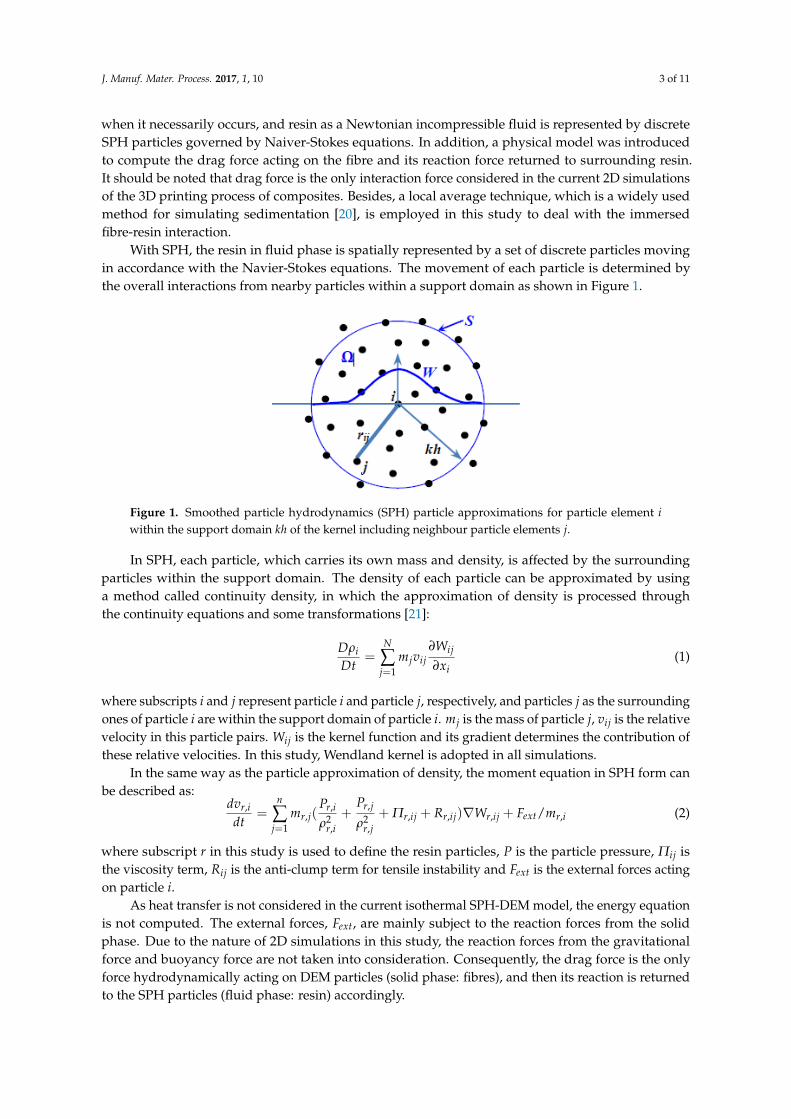
With SPH, the resin in fluid phase is spatially represented by a set of discrete particles moving
in accordance with the Navier-Stokes equations. The movement of each particle is determined by
the overall interactions from nearby particles within a support domain as shown in Figure 1.
件倦月 倹
経貢沈経建 噺 布 兼珍懸沈珍朝珍退怠
項激沈珍項捲沈件andj 件 倹 倹件 件 兼珍倹 懸沈珍 激沈珍
穴懸追┸沈穴建 噺 布 兼追┸珍岫鶏追┸沈貢追┸沈態 髪 鶏追┸珍貢追┸珍態 髪 梗追┸沈珍 髪 迎追┸沈珍岻稿激追┸沈珍津珍退怠 髪 繋勅掴痛【兼追┸沈
堅 鶏 梗沈珍迎沈珍 繋勅掴痛件 繋勅掴痛
Figure 1. Smoothed particle hydrodynamics (SPH) particle approximations for particle element i
within the support domain kh of the kernel including neighbour particle elements j.
In SPH, each particle, which carries its own mass and density, is affected by the surrounding
particles within the support domain. The density of each particle can be approximated by using
a method called continuity density, in which the approximation of density is processed through
the continuity equations and some transformations [21]:
Dρi
Dt=
N
∑j=1
mjvij
∂Wij
∂xi(1)
where subscripts i and j represent particle i and particle j, respectively, and particles j as the surrounding
ones of particle i are within the support domain of particle i. mj is the mass of particle j, vij is the relative
velocity in this particle pairs. Wij is the kernel function and its gradient determines the contribution of
these relative velocities. In this study, Wendland kernel is adopted in all simulations.
In the same way as the particle approximation of density, the moment equation in SPH form can
be described as:dvr,i
dt=
n
∑j=1
mr,j(Pr,i
ρ2r,i
+Pr,j
ρ2r,j
+ Πr,ij + Rr,ij)∇Wr,ij + Fext/mr,i (2)
where subscript r in this study is used to define the resin particles, P is the particle pressure, Πij is
the viscosity term, Rij is the anti-clump term for tensile instability and Fext is the external forces acting
on particle i.
As heat transfer is not considered in the current isothermal SPH-DEM model, the energy equation
is not computed. The external forces, Fext, are mainly subject to the reaction forces from the solid
phase. Due to the nature of 2D simulations in this study, the reaction forces from the gravitational
force and buoyancy force are not taken into consideration. Consequently, the drag force is the only
force hydrodynamically acting on DEM particles (solid phase: fibres), and then its reaction is returned
to the SPH particles (fluid phase: resin) accordingly.
J. Manuf. Mater. Process. 2017, 1, 10 4 of 11
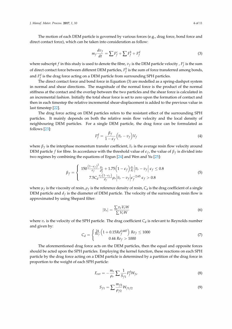
The motion of each DEM particle is governed by various forces (e.g., drag force, bond force and
direct contact force), which can be taken into consideration as follow:
m f
dv f
dt= ∑ Fc
f + ∑ Fbf + Fd
f (3)
where subscript f in this study is used to denote the fibre, v f is the DEM particle velocity , Fcf is the sum
of direct contact force between different DEM particles, Fbf is the sum of force transferred among bonds,
and Fdf is the drag force acting on a DEM particle from surrounding SPH particles.
The direct contact force and bond force in Equation (3) are modelled as a spring-dashpot system
in normal and shear directions. The magnitude of the normal force is the product of the normal
stiffness at the contact and the overlap between the two particles and the shear force is calculated in
an incremental fashion. Initially the total shear force is set to zero upon the formation of contact and
then in each timestep the relative incremental shear-displacement is added to the previous value in
last timestep [22].
The drag force acting on DEM particles refers to the resistant effect of the surrounding SPH
particles. It mainly depends on both the relative resin flow velocity and the local density of
neighbouring DEM particles. For a single DEM particle, the drag force can be formulated as
follows [23]:
Fdf =
β f
1 − ǫ f
(
vr − v f
)
Vf (4)
where β f is the interphase momentum transfer coefficient, vr is the average resin flow velocity around
DEM particle f for fibre. In accordance with the threshold value of ǫ f , the value of β f is divided into
two regimes by combining the equations of Ergun [24] and Wen and Yu [25]:
β f =
150(1−ǫ f )
2
ǫ f
µr
d2f
+ 1.75(
1 − ǫ f
)
ρr
dr
∣
∣
∣vr − v f
∣
∣
∣ǫ f ≤ 0.8
7.5Cdǫ f (1−ǫ f )
d fρr
∣
∣
∣vr − v f
∣
∣
∣ǫ−2.65
f ǫ f > 0.8
(5)
where µ f is the viscosity of resin, ρ f is the reference density of resin, Cd is the drag coefficient of a single
DEM particle and d f is the diameter of DEM particle. The velocity of the surrounding resin flow is
approximated by using Shepard filter:
|vr| =∑ vrVrW
∑ VrW(6)
where vr is the velocity of the SPH particle. The drag coefficient Cd is relevant to Reynolds number
and given by:
Cd =
{
24Re f
(
1 + 0.15Re0.687f
)
Re f ≤ 1000
0.44 Re f > 1000(7)
The aforementioned drag force acts on the DEM particles, then the equal and opposite forces
should be acted upon the SPH particles. Employing the kernel function, these reactions on each SPH
particle by the drag force acting on a DEM particle is determined by a partition of the drag force in
proportion to the weight of each SPH particle:
Fext = −mr
ρr∑
1
S f 1Fd
f W f r (8)
S f 1 = ∑m f 2
ρ f 2W f 1 f 2 (9)
J. Manuf. Mater. Process. 2017, 1, 10 5 of 11
Replacing the external force term Fext in the momentum equation for fluid phase, we find that
Equation (2) becomes:
dvr,i
dt=
n
∑j=1
mr,j(Pr,i
ρ2r,i
+Pr,j
ρ2r,j
+ Πr,ij + Rr,ij)∇Wr,ij − (mr
ρr∑
1
S f 1Fd
f W f r)/mr,i (10)
The acceleration of SPH and DEM particles obtained from Equations (2) and (3) will be used to
calculate the velocity and displacement using a central difference method. The position of the each
particle is updated according to the new displacement and a new computation circle starts with
the searching of neighbour particles. Details of SPH and DEM approaches and their coupling as well
as validations are referred to [17].
3. Numerical Study
Two cases of 3D printing of composites are investigated using the coupled SPH-DEM model to
demonstrate its capability and potential for simulating the printing process of short and continuous
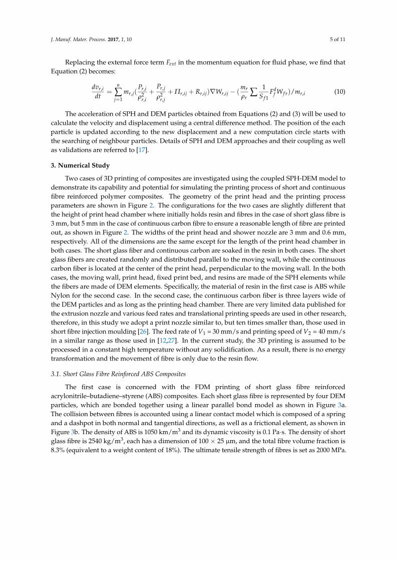
fibre reinforced polymer composites. The geometry of the print head and the printing process
parameters are shown in Figure 2. The configurations for the two cases are slightly different that
the height of print head chamber where initially holds resin and fibres in the case of short glass fibre is
3 mm, but 5 mm in the case of continuous carbon fibre to ensure a reasonable length of fibre are printed
out, as shown in Figure 2. The widths of the print head and shower nozzle are 3 mm and 0.6 mm,
respectively. All of the dimensions are the same except for the length of the print head chamber in
both cases. The short glass fiber and continuous carbon are soaked in the resin in both cases. The short
glass fibers are created randomly and distributed parallel to the moving wall, while the continuous
carbon fiber is located at the center of the print head, perpendicular to the moving wall. In the both
cases, the moving wall, print head, fixed print bed, and resins are made of the SPH elements while
the fibers are made of DEM elements. Specifically, the material of resin in the first case is ABS while
Nylon for the second case. In the second case, the continuous carbon fiber is three layers wide of
the DEM particles and as long as the printing head chamber. There are very limited data published for
the extrusion nozzle and various feed rates and translational printing speeds are used in other research,
therefore, in this study we adopt a print nozzle similar to, but ten times smaller than, those used in
short fibre injection moulding [26]. The feed rate of V1 = 30 mm/s and printing speed of V2 = 40 mm/s
in a similar range as those used in [12,27]. In the current study, the 3D printing is assumed to be
processed in a constant high temperature without any solidification. As a result, there is no energy
transformation and the movement of fibre is only due to the resin flow.
3.1. Short Glass Fibre Reinforced ABS Composites
The first case is concerned with the FDM printing of short glass fibre reinforced
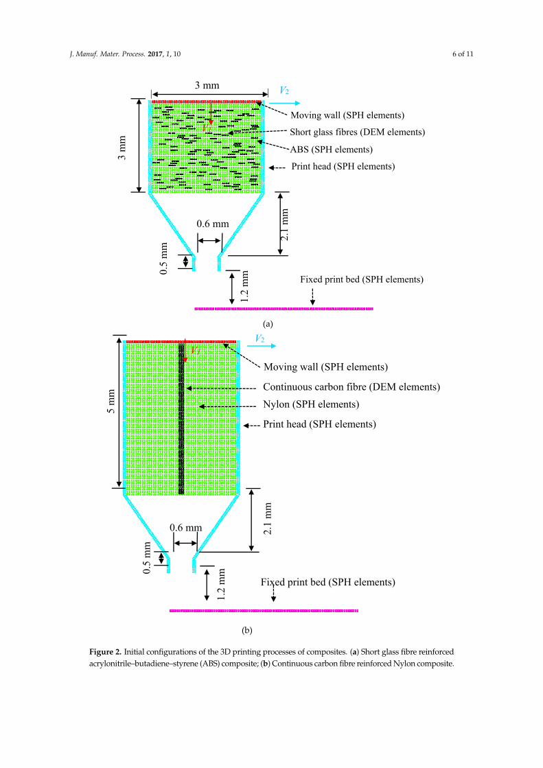
acrylonitrile–butadiene–styrene (ABS) composites. Each short glass fibre is represented by four DEM
particles, which are bonded together using a linear parallel bond model as shown in Figure 3a.
The collision between fibres is accounted using a linear contact model which is composed of a spring
and a dashpot in both normal and tangential directions, as well as a frictional element, as shown in
Figure 3b. The density of ABS is 1050 km/m3 and its dynamic viscosity is 0.1 Pa·s. The density of short
glass fibre is 2540 kg/m3, each has a dimension of 100 × 25 µm, and the total fibre volume fraction is
8.3% (equivalent to a weight content of 18%). The ultimate tensile strength of fibres is set as 2000 MPa.
J. Manuf. Mater. Process. 2017, 1, 10 6 of 11
(a)
0.6 mm
0.5
mm
2.1
mm
1.2
mm
3 m
m
3 mm V2
V1
Moving wall (SPH elements)
Short glass fibres (DEM elements)
Print head (SPH elements)
ABS (SPH elements)
Fixed print bed (SPH elements)
(b)
ȉ
5 m
m
V1
Moving wall (SPH elements)
Continuous carbon fibre (DEM elements)
Print head (SPH elements)
Nylon (SPH elements)
Fixed print bed (SPH elements)
V2
0.5
mm
2.1
mm
1.2
mm
0.6 mm
Figure 2. Initial configurations of the 3D printing processes of composites. (a) Short glass fibre reinforced
acrylonitrile–butadiene–styrene (ABS) composite; (b) Continuous carbon fibre reinforced Nylon composite.
J. Manuf. Mater. Process. 2017, 1, 10 7 of 11
ȉ
(a)
(b)
喧銚 喧長倦博 倦博航 購博 潔違and剛博
ȉ
倦博津 噺 継迎銚 髪 迎長倦博鎚 噺 倦博津倦
Figure 3. (a) A short glass fibre represented by four bonded Discrete Element Method (DEM) particles.
(b) The components of linear parallel bond model, connecting particles pa and pb. Here kn and ks are
the normal and shear spring stiffness, kn and ks are the normal and shear bond stiffness, gs is the surface
gap between two particles, µ is the friction coefficient, σn is the tensile strength, c and φ are cohesion
and friction angle.
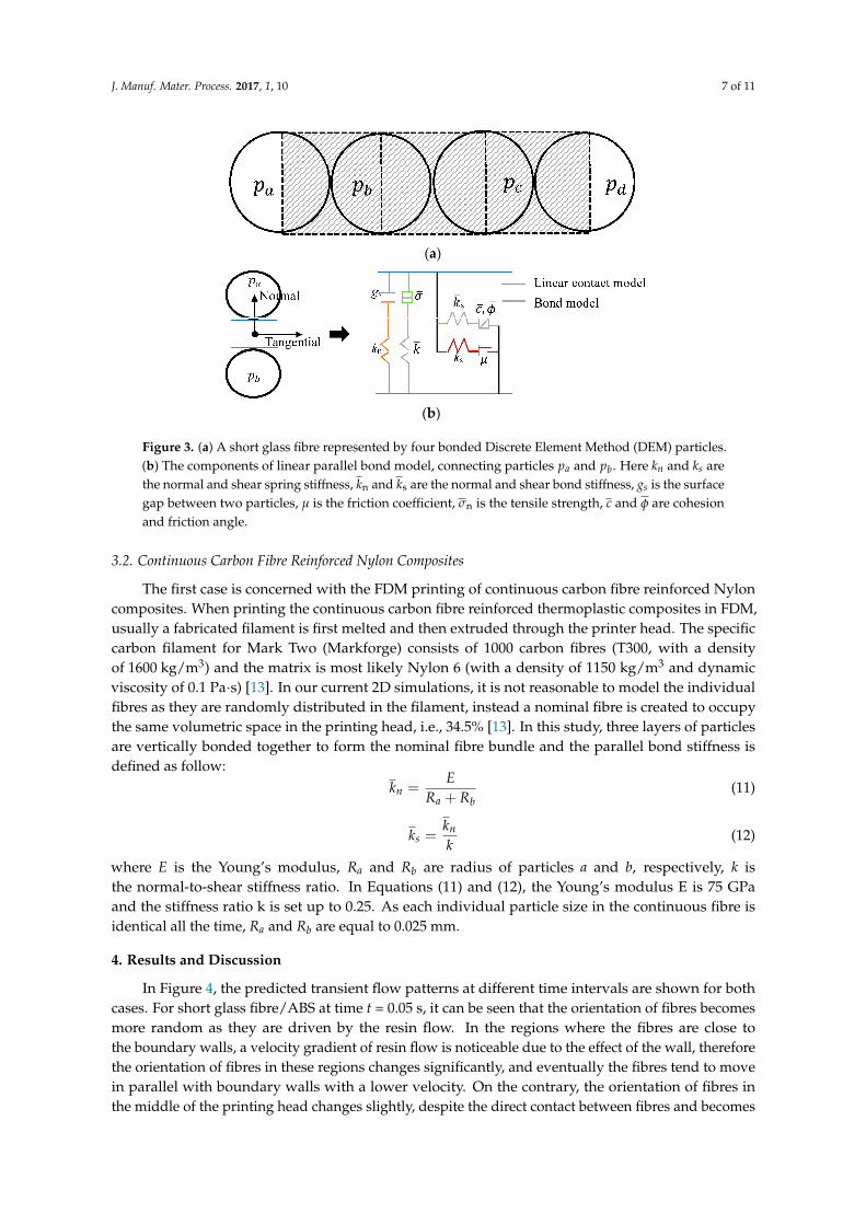
3.2. Continuous Carbon Fibre Reinforced Nylon Composites
The first case is concerned with the FDM printing of continuous carbon fibre reinforced Nylon
composites. When printing the continuous carbon fibre reinforced thermoplastic composites in FDM,
usually a fabricated filament is first melted and then extruded through the printer head. The specific
carbon filament for Mark Two (Markforge) consists of 1000 carbon fibres (T300, with a density
of 1600 kg/m3) and the matrix is most likely Nylon 6 (with a density of 1150 kg/m3 and dynamic
viscosity of 0.1 Pa·s) [13]. In our current 2D simulations, it is not reasonable to model the individual
fibres as they are randomly distributed in the filament, instead a nominal fibre is created to occupy
the same volumetric space in the printing head, i.e., 34.5% [13]. In this study, three layers of particles
are vertically bonded together to form the nominal fibre bundle and the parallel bond stiffness is
defined as follow:
kn =E
Ra + Rb(11)
ks =kn
k(12)
where E is the Young’s modulus, Ra and Rb are radius of particles a and b, respectively, k is
the normal-to-shear stiffness ratio. In Equations (11) and (12), the Young’s modulus E is 75 GPa
and the stiffness ratio k is set up to 0.25. As each individual particle size in the continuous fibre is
identical all the time, Ra and Rb are equal to 0.025 mm.
4. Results and Discussion
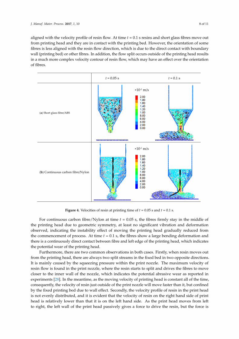
In Figure 4, the predicted transient flow patterns at different time intervals are shown for both
cases. For short glass fibre/ABS at time t = 0.05 s, it can be seen that the orientation of fibres becomes
more random as they are driven by the resin flow. In the regions where the fibres are close to
the boundary walls, a velocity gradient of resin flow is noticeable due to the effect of the wall, therefore
the orientation of fibres in these regions changes significantly, and eventually the fibres tend to move
in parallel with boundary walls with a lower velocity. On the contrary, the orientation of fibres in
the middle of the printing head changes slightly, despite the direct contact between fibres and becomes
J. Manuf. Mater. Process. 2017, 1, 10 8 of 11
aligned with the velocity profile of resin flow. At time t = 0.1 s resins and short glass fibres move out
from printing head and they are in contact with the printing bed. However, the orientation of some
fibres is less aligned with the resin flow direction, which is due to the direct contact with boundary
wall (printing bed) or other fibres. In addition, the flow split occurs outside of the printing head results
in a much more complex velocity contour of resin flow, which may have an effect over the orientation
of fibres.
t = 0.05 s t = 0.1 s
(a) Short glass fibre/ABS
(b) Continuous carbon fibre/Nylon
×10-1 m/s
×10-1 m/s
Figure 4. Velocities of resin at printing time of t = 0.05 s and t = 0.1 s.
For continuous carbon fibre/Nylon at time t = 0.05 s, the fibres firmly stay in the middle of
the printing head due to geometric symmetry, at least no significant vibration and deformation
observed, indicating the instability effect of moving the printing head gradually reduced from
the commencement of process. At time t = 0.1 s, the fibres show a large bending deformation and
there is a continuously direct contact between fibre and left edge of the printing head, which indicates
the potential wear of the printing head.
Furthermore, there are two common observations in both cases. Firstly, when resin moves out
from the printing head, there are always two split streams in the fixed bed in two opposite directions.
It is mainly caused by the squeezing pressure within the print nozzle. The maximum velocity of
resin flow is found in the print nozzle, where the resin starts to split and drives the fibres to move
closer to the inner wall of the nozzle, which indicates the potential abrasive wear as reported in
experiments [28]. In the meantime, as the moving velocity of printing head is constant all of the time,
consequently, the velocity of resin just outside of the print nozzle will move faster than it, but confined
by the fixed printing bed due to wall effect. Secondly, the velocity profile of resin in the print head
is not evenly distributed, and it is evident that the velocity of resin on the right hand side of print
head is relatively lower than that it is on the left hand side. As the print head moves from left
to right, the left wall of the print head passively gives a force to drive the resin, but the force is
J. Manuf. Mater. Process. 2017, 1, 10 9 of 11
firstly transferred to the resin close to the left wall of print head, therefore, there is a delay in force
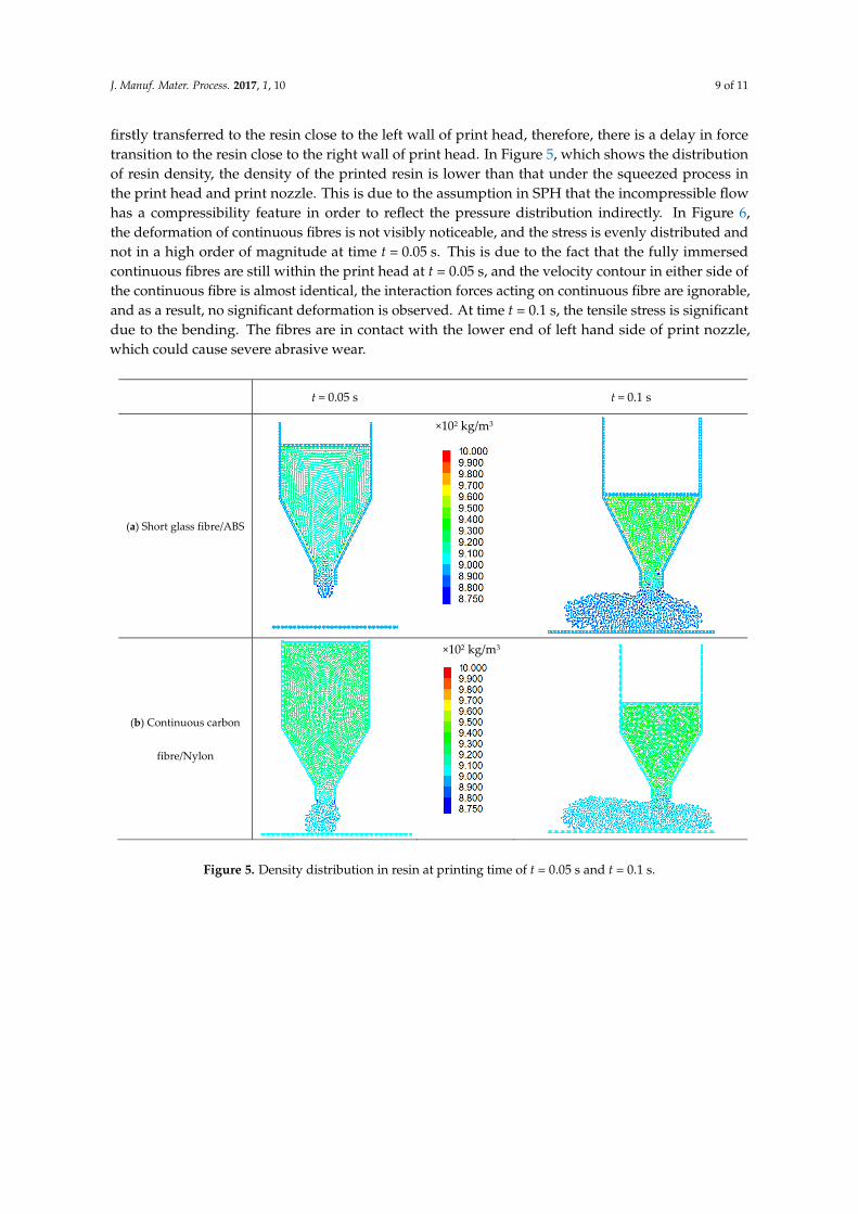
transition to the resin close to the right wall of print head. In Figure 5, which shows the distribution
of resin density, the density of the printed resin is lower than that under the squeezed process in
the print head and print nozzle. This is due to the assumption in SPH that the incompressible flow
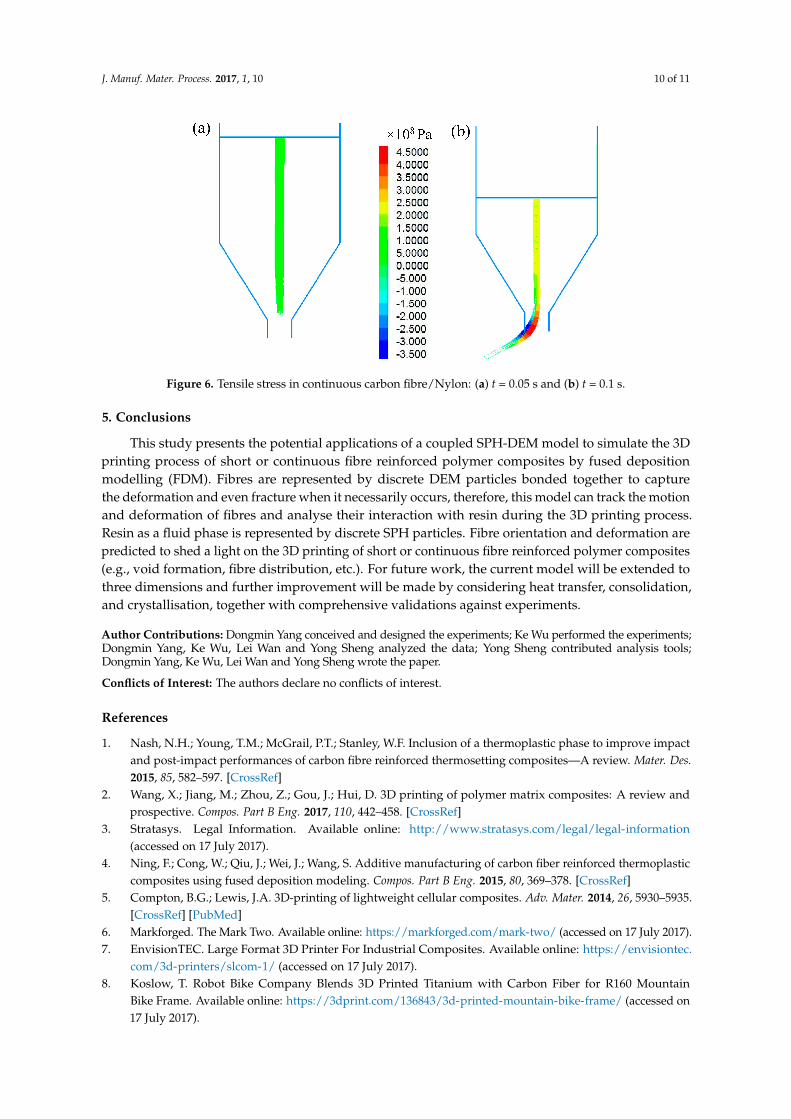
has a compressibility feature in order to reflect the pressure distribution indirectly. In Figure 6,
the deformation of continuous fibres is not visibly noticeable, and the stress is evenly distributed and
not in a high order of magnitude at time t = 0.05 s. This is due to the fact that the fully immersed
continuous fibres are still within the print head at t = 0.05 s, and the velocity contour in either side of
the continuous fibre is almost identical, the interaction forces acting on continuous fibre are ignorable,
and as a result, no significant deformation is observed. At time t = 0.1 s, the tensile stress is significant
due to the bending. The fibres are in contact with the lower end of left hand side of print nozzle,
which could cause severe abrasive wear.
t = 0.05 s t = 0.1 s
(a) Short glass fibre/ABS
(b) Continuous carbon
fibre/Nylon
×102 kg/m3
×102 kg/m3
Figure 5. Density distribution in resin at printing time of t = 0.05 s and t = 0.1 s.
J. Manuf. Mater. Process. 2017, 1, 10 10 of 11
Figure 6. Tensile stress in continuous carbon fibre/Nylon: (a) t = 0.05 s and (b) t = 0.1 s.
5. Conclusions
This study presents the potential applications of a coupled SPH-DEM model to simulate the 3D
printing process of short or continuous fibre reinforced polymer composites by fused deposition
modelling (FDM). Fibres are represented by discrete DEM particles bonded together to capture
the deformation and even fracture when it necessarily occurs, therefore, this model can track the motion
and deformation of fibres and analyse their interaction with resin during the 3D printing process.
Resin as a fluid phase is represented by discrete SPH particles. Fibre orientation and deformation are
predicted to shed a light on the 3D printing of short or continuous fibre reinforced polymer composites
(e.g., void formation, fibre distribution, etc.). For future work, the current model will be extended to
three dimensions and further improvement will be made by considering heat transfer, consolidation,
and crystallisation, together with comprehensive validations against experiments.
Author Contributions: Dongmin Yang conceived and designed the experiments; Ke Wu performed the experiments;Dongmin Yang, Ke Wu, Lei Wan and Yong Sheng analyzed the data; Yong Sheng contributed analysis tools;Dongmin Yang, Ke Wu, Lei Wan and Yong Sheng wrote the paper.
Conflicts of Interest: The authors declare no conflicts of interest.
References
1. Nash, N.H.; Young, T.M.; McGrail, P.T.; Stanley, W.F. Inclusion of a thermoplastic phase to improve impact
and post-impact performances of carbon fibre reinforced thermosetting composites—A review. Mater. Des.
2015, 85, 582–597. [CrossRef]
2. Wang, X.; Jiang, M.; Zhou, Z.; Gou, J.; Hui, D. 3D printing of polymer matrix composites: A review and
prospective. Compos. Part B Eng. 2017, 110, 442–458. [CrossRef]
3. Stratasys. Legal Information. Available online: http://www.stratasys.com/legal/legal-information
(accessed on 17 July 2017).
4. Ning, F.; Cong, W.; Qiu, J.; Wei, J.; Wang, S. Additive manufacturing of carbon fiber reinforced thermoplastic
composites using fused deposition modeling. Compos. Part B Eng. 2015, 80, 369–378. [CrossRef]
5. Compton, B.G.; Lewis, J.A. 3D-printing of lightweight cellular composites. Adv. Mater. 2014, 26, 5930–5935.
[CrossRef] [PubMed]
6. Markforged. The Mark Two. Available online: https://markforged.com/mark-two/ (accessed on 17 July 2017).
7. EnvisionTEC. Large Format 3D Printer For Industrial Composites. Available online: https://envisiontec.
com/3d-printers/slcom-1/ (accessed on 17 July 2017).
8. Koslow, T. Robot Bike Company Blends 3D Printed Titanium with Carbon Fiber for R160 Mountain
Bike Frame. Available online: https://3dprint.com/136843/3d-printed-mountain-bike-frame/ (accessed on
17 July 2017).

J. Manuf. Mater. Process. 2017, 1, 10 11 of 11
9. Llewellyn-Jones, T.M.; Drinkwater, B.W.; Trask, R.S. 3D printed components with ultrasonically arranged
microscale structure. Smart Mater. Struct. 2016, 25, 02LT1. [CrossRef]
10. Martin, J.J.; Fiore, B.E.; Erb, R.M. Designing bioinspired composite reinforcement architectures via 3D
magnetic printing. Nat. Commun. 2015. [CrossRef] [PubMed]
11. Spackman, C.C.; Frank, C.R.; Picha, K.C.; Samuel, J. 3D printing of fiber-reinforced soft composites:
Process study and material characterization. J. Manuf. Process. 2016, 23, 296–305. [CrossRef]
12. Ning, F.; Cong, W.; Hu, Z.; Huang, K. Additive manufacturing of thermoplastic matrix composites using
fused deposition modeling: A comparison of two reinforcements. J. Compos. Mater. 2017. [CrossRef]
13. Van Der Klift, F.; Koga, Y.; Todoroki, A.; Ueda, M.; Hirano, Y.; Matsuzaki, R. 3D printing of continuous
carbon fibre reinforced thermo-plastic (CFRTP) tensile test specimens. Open J. Compos. Mater. 2015, 6, 18.
[CrossRef]
14. Singh, R.; Singh, S.; Singh, I.P.; Fabbrocino, F.; Fraternali, F. Investigation for surface finish improvement of
FDM parts by vapor smoothing process. Compos. Part B Eng. 2017, 111, 228–234. [CrossRef]
15. Souness, A.; Zamboni, F.; Walker, G.M.; Collins, M.N. Influence of scaffold design on 3D printed
cell constructs. J. Biomed. Mater. Res. Part B Appl. Biomater. 2017. [CrossRef] [PubMed]
16. Wu, K.; Yang, D.; Wright, N. A coupled SPH-DEM model for fluid-structure interaction problems with
free-surface flow and structural failure. Comput. Struct. 2016, 177, 141–161. [CrossRef]
17. Wu, K.; Yang, D.; Wright, N.; Khan, A. An integrated particle model for fluid-particle-structure interaction
problems with free-surface flow and structural failure. J. Fluids Struct. 2017. submitted.
18. Makino, M.; Fukuzawa, D.; Murashima, T.; Kawakami, M.; Furukawa, H. Analysis of deposition modeling
by particle method simulation. Microsyst. Technol. 2017, 23, 1177–1181. [CrossRef]
19. Steuben, J.C.; Iliopoulos, A.P.; Michopoulos, J.G. Discrete element modeling of particle-based additive
manufacturing processes. Comput. Methods Appl. Mech. Eng. 2016, 305, 537–561. [CrossRef]
20. Anderson, T.B.; Jackson, R. Fluid mechanical description of fluidized beds. Equations of motion. Ind. Eng.
Chem. Fundam. 1967, 6, 527–539. [CrossRef]
21. Liu, G.R.; Liu, M.B. Smoothed Particle Hydrodynamics: A Meshfree Particle Method; World Scientific:
Singapore, 2003.
22. Itasca Consulting Group, Inc. PFC 5.0 Documentation; Itasca Consulting Group: Minneapolis, MN, USA, 2011.
23. Sun, X.; Sakai, M.; Yamada, Y. Three-dimensional simulation of a solid–liquid flow by the DEM–SPH method.
J. Comput. Phys. 2013, 248, 147–176. [CrossRef]
24. Ergun, S. Fluid flow through packed columns. Chem. Eng. Prog. 1952, 48, 89–94.
25. Wen, C.; Yu, Y. Mechanics of fluidization. Chem. Eng. Prog. Symp. Ser. 2013, 6, 100–101.
26. Yashiro, S.; Okabe, T.; Matsushima, K. A numerical approach for injection molding of short-fiber-reinforced
plastics using a particle method. Adv. Compos. Mater. 2011, 20, 503–517. [CrossRef]
27. Tian, X.; Liu, T.; Yang, C.; Wang, Q.; Li, D. Interface and performance of 3D printed continuous carbon fiber
reinforced PLA composites. Compos. Part A Appl. Sci. Manuf. 2016, 88, 198–205. [CrossRef]
28. Kraft, C. Detailed Breakdown: How Carbon Fiber Filament Ruins 3D Printer Nozzles. Available online:
http://makezine.com/2015/09/11/carbon-fiber-filament-ruins-nozzles/ (accessed on 17 July 2017).
© 2017 by the authors. Licensee MDPI, Basel, Switzerland. This article is an open access
article distributed under the terms and conditions of the Creative Commons Attribution
(CC BY) license (http://creativecommons.org/licenses/by/4.0/).