Embed Size (px)
Citation preview

A Passive Pediatric Exoskeleton to Improve the Walking Ability
of Children with Neuromuscular Disorders
Jessica Zistatsis
A thesis
submitted in partial fulfillment of the
requirements for the degree of
MASTER OF SCIENCE IN MECHANICAL ENGINEERING
University of Washington
2018
Committee:
Katherine M. Steele
Kristie Bjornson
Patrick Aubin
Mark Ganter
Program Authorized to Offer Degree:
Mechanical Engineering

ii
©Copyright 2018
Jessica Zistatsis

iii
University of Washington
Abstract
A Passive Pediatric Exoskeleton to Improve the Walking Ability
of Children with Neuromuscular Disorders
Jessica Zistatsis
Chair of the Supervisory Committee:
Katherine M. Steele, Ph.D.
Assistant Professor
Mechanical Engineering
Children with neuromuscular disorders, such as cerebral palsy (CP) often have walking
limitations. Assistive devices for home use, such as walkers and crutches, may not provide
optimal participation opportunities or lead to effective walking dosage. Even with therapy and
assistive devices, children with CP get significantly less walking practice than typically
developing peers. Recent research has shown that passive exotendon driven exoskeletons are
effective for improving walking outcomes for adults with neurologic injury. A passive pediatric
exoskeleton using exotendons was developed and evaluated for improving gait of children with
CP and other forms of hemiparesis. Three typically developing (TD) children and two children
with hemiparesis walked on level ground with the exoskeleton at three stiffness settings. Motion
capture and electromyography data were collected to evaluate changes in joint kinematic
symmetry, walking speed, and step width. The exoskeleton had no significant impact on gait

iv
outcome measures for TD participants, but for participants with hemiparesis the exoskeleton
significantly improved kinematic joint symmetry at the hip or the ankle depending on the
participant’s natural gait pattern. These results suggest that exotendon-based designs for passive
exoskeletons may provide a novel platform to improve walking for children with neurologic
injuries and support community-based gait training.

v
Table of Contents
Chapter 1 INTRODUCTION ............................................................................................... 10
1.1 Cerebral Palsy ............................................................................................................. 10
1.2 Cerebral Palsy Gait and Activity ................................................................................. 11
1.3 Current Rehabilitation and Assistive Device Solutions ................................................ 13
1.3.1 Clinical Solutions ................................................................................................. 13
1.3.2 Home and Community Solutions.......................................................................... 16
1.4 Exotendon-Based Exoskeletons ................................................................................... 17
1.5 Thesis Objective ......................................................................................................... 18
Chapter 2 DEVICE DEVELOPMENT ................................................................................. 20
2.1 Core Functions and Design Specifications ................................................................... 20
2.2 PlayGait Design .......................................................................................................... 22
2.3 Device Evaluation ....................................................................................................... 26
Chapter 3 PARTICIPANT TESTING .................................................................................. 28
3.1 Aim & Hypotheses ...................................................................................................... 28
3.2 Methods ...................................................................................................................... 29
3.2.1 Participant Demographics .................................................................................... 29
3.2.2 Data Collection .................................................................................................... 29
3.2.3 Data Processing ................................................................................................... 34
3.2.4 Outcome Measure Calculations ............................................................................ 35
3.3 Results ........................................................................................................................ 38
3.3.1 Kinematics ........................................................................................................... 38
3.3.2 Spatiotemporal ..................................................................................................... 43
3.3.3 Electromyography ................................................................................................ 45
3.4 Discussion................................................................................................................... 47
3.4.1 Kinematic Symmetry ........................................................................................... 47
3.4.2 Walking Speed and Step Width ............................................................................ 48
3.4.3 Electromyography ................................................................................................ 49
3.4.4 Limitations........................................................................................................... 50
3.4.5 Recommendations for Future Work...................................................................... 51
Chapter 4 CONCLUSION.................................................................................................... 53
vi
References ............................................................................................................................ 54
Appendix A: Design Specifications ........................................................................................... 59
Appendix B: Mechanical Testing .............................................................................................. 62
Appendix C: Motion Capture Study Protocol ............................................................................ 68
Appendix D: OpenSim Musculoskeletal Modeling and Simulation............................................ 75
Appendix E: Inverse Kinematics and Correlation Plots for all Conditions ................................. 84
Appendix F: Electromyography Results .................................................................................... 94

vii
LIST OF FIGURES
Figure 2-1: Kickstart®, a passive adult exoskeleton produced by Cadence Biomedical. ............ 20
Figure 2-2: A CAD rendering of PlayGait, a passive pediatric exoskeleton, demonstrating the
bilateral configuration. .............................................................................................................. 22
Figure 2-3: Section view of an assembled hip pulley mechanism featuring the Geneva
mechanism. ............................................................................................................................... 23
Figure 2-4: An exploded view of PlayGait's hip pulley mechanism. The spiral torsion spring
(black) shares an axis of rotation with the geneva mechanism (gray disk and pin). .................... 23
Figure 2-5: A unilateral assembly of PlayGait showcasing the spiral torsion spring in the hip
assembly (top) connected to an exotendon wrapping anteriorly around the hip and knee pulleys
and wrapping posteriorly around the ankle pulley. ..................................................................... 23
Figure 2-6: The spool used to store extra exotendon length while preloading the spring. ........... 24
Figure 2-7: Leg strut featuring a telescoping mechanism. .......................................................... 24
Figure 2-8: Example custom foot orthosis attaching to PlayGait's ankle joint. ........................... 25
Figure 2-9: A footplate design featuring slots through which to loop Velcro. The inset area holds
the stirrup which connects the footplate to the ankle. ................................................................. 25
Figure 3-1: Modified Helen Hayes marker set (red dots) used for motion capture. Black boxes
represent EMG sensors. ............................................................................................................. 32
Figure 3-2: MATLAB data processing pipeline to generate outcomes of step width, walking
speed, muscle activations and kinematics. ................................................................................. 35
Figure 3-3: Kinematic symmetry comparison for the average of the No Exo trials for one TD
subject. The left column depicts the unimpaired/left leg joint angles plotted against the
impaired/right leg joint angles. High symmetry is indicated by a linear fit slope line with high
correlation to the angle-angle trendline. ..................................................................................... 37
Figure 3-4: Average R2 coefficient of each joint by condition for TD participants. Error bars
represent the standard deviation of R2 values for the three TD participants. ............................... 41
Figure 3-5: R2 coefficient for each joint versus condition for participant H1. ............................. 42
Figure 3-6: R2 coefficient for each joint versus condition for participant H2. ............................. 42
Figure 3-7: Nondimensionalized walking speed for each participant across conditions. Error bars
represent standard deviations across trials. ................................................................................ 44
Figure 3-8: Normalized step width for each participant across conditions. Error bars represent the
standard deviation across trials. ................................................................................................. 45
Figure 3-9: Muscle activations for a TD participant ................................................................... 46
Figure 3-10: Comparison of muscle activation in the biceps femoris and medial gastric. for a
representative TD participant and both participants with hemiparesis. ....................................... 47

viii
LIST OF TABLES
Table 1-1: Characteristics of GMFCS Levels. ........................................................................... 12
Table 2-1: Comparison of PlayGait and other assistive devices. ................................................ 27
Table 3-1: Demographic data. ................................................................................................... 31
Table 3-2: Electromyography sensor placement and type. ......................................................... 32
Table 3-3 Walking trials for motion capture. ............................................................................. 33
Table 3-4 Spring stiffness for each participant. .......................................................................... 34
Table 3-5: R2 correlation coefficients quantifying level of symmetry between participants' left
and right legs............................................................................................................................. 39
Table 3-6: Slopes of linear fit comparing participants' left and right kinematics for each condition
................................................................................................................................................. 40

ix
ACKNOWLEDGEMENTS
I would like to acknowledge Kristie Bjornson, PhD, PT for her assistance with this work and
expertise in clinical studies of cerebral palsy and Brian Glaister, COO for inspiring the
development of a pediatric exoskeleton. Thank you to Katherine Steele, PhD for advising this
research and to Keshia Peters, Heather Feldner, PhD, PT, Daniel Ballesteros, and Brianna
Goodwin for assisting with data collection and processing. Also, thank you to Chris Richburg at
the Seattle VA Hospital for assistance with 3D printing and to Andrea Willson for providing
MATLAB code and assisting with OpenSim. Thanks to Alex Gong, Daniel Parrish, Jeffrey
Bergeson, and Kira Newman for their excellent teamwork during initial prototype development
in the University of Washington’s Engineering Innovations in Health capstone course. Sections
from the capstone report are included in this thesis.
Additionally, I would like to acknowledge my funding sources: the CoMotion Innovation
Fund, the NEPDC and FDA award P50FD004907 and TREAT and NIH award R24HD065703
and P2CHD086841, the Orthotic and Prosthetic Education and Research Foundation, Inc.
(OPERF) under grant number OPERF-2017-FA-1, and a 2017 Developmental Grant from the
University of Washington Global Center for Integrated Health of Women, Adolescents, and
Children (Global WACh) and the University of Washington Coulter Translational Research
Partnership Program.

10
Chapter 1 INTRODUCTION
Hemiparesis is a neurologic condition in which half the body is affected by motor
impairments. There are many causes for hemiparesis such as stroke, spinal cord injury, and viral
infections such as nonpolio enterovirus-D68 (Khetsuriani et al. 2006). However, the largest
cause of hemiparesis among children is cerebral palsy (CP) (NSCIS 2004, Krigger 2006,
Agrawal et al. 2009). As such, the following sections provide background on CP and currently
available assistive devices for children with CP since this is the largest population that informed
and motivated this research.
1.1 Cerebral Palsy
Approximately 2-3.8 out of every 1000 children born in the United States (US) are
diagnosed with CP (Krigger 2006, Cans et al. 2008, Yeargin-Allsopp et al. 2008). This
population has been mostly steady or slightly downward trending depending on a child’s birth
weight since the 1980s both in the US and Europe (Cans et al. 2008). In 2013, there were 10,000
infants born in the US with CP, with an additional 1200-1500 preschoolers diagnosed (Palsy
2013).
CP is a non-progressive neurologic condition resulting from brain injury before, during,
or shortly after birth that causes impaired movement (CerebralPalsy.org , Krigger 2006).
Individuals with CP are typically classified into bilateral CP, in which both sides of the body are
affected, or unilateral CP, in which one side of the body is affected. Subtypes of these
classifications include quadriplegia, diplegia, and hemiplegia. Quadriplegia affects all four limbs,
diplegia affects both legs, and hemiplegia affects both limbs on the same side of the body. A

11
study of nearly 500 children with CP in the US reported that quadriplegia affects 15%, diplegia
affects 59%, and hemiplegia affects 23% (Wren et al. 2005).
The cost of care for individuals with CP varies by country, but was estimated to be
$920,000 per individual (2003 dollars) in the US over an individual’s lifetime (Honeycutt A
2004). Assistive devices for children cost at any given point in time an average of $3,416 (1989
dollars) per child across all devices used by children in the home, daycare, and school
environments, with orthoses and prostheses accounting for 23.4% and personal mobility devices
accounting for 26.5% of the these costs (Korpela et al. 1992).
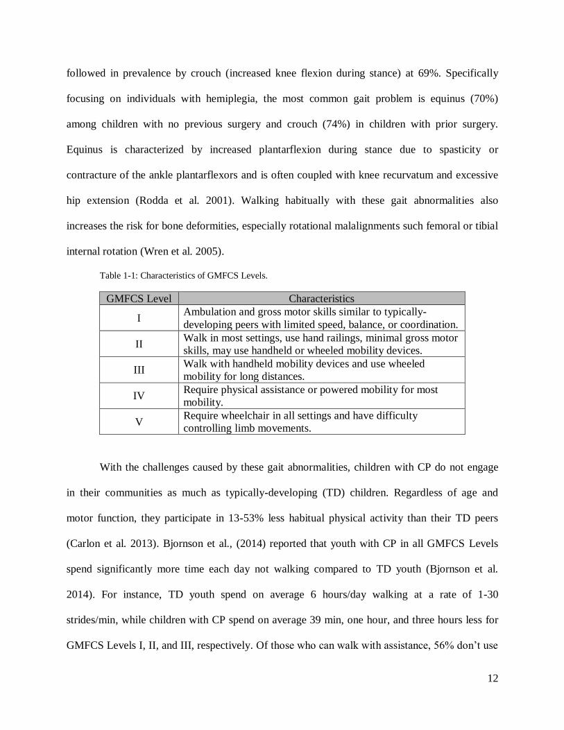
1.2 Cerebral Palsy Gait and Activity
CP ambulation levels are typically categorized by the Gross Motor Function
Classification System (GMFCS). Classification ranges from Level I (mild, requiring no assistive
devices) to Level V (severe, requiring powered mobility devices, Table 1.1) (Palisano et al.
1997). In a study of children with CP in nine countries, it was found that 59.3% have mild
impairment (Levels I-II), 11.5% have moderate impairment (Level III), and 29.3% have severe
impairment (Levels IV-V) (Reid et al. 2011). A longitudinal study demonstrated that motor
function declines through adolescence for GMFCS levels III-V, with peak function at an
approximate age of 7 years (Hanna et al. 2009).
Children with CP demonstrate a wide variety of gait patterns. The most common gait
abnormality is stiff knee gait, defined by Wren et al., (2005) as “decreased arc of knee motion
from maximum knee extension in stance to peak knee flexion in swing, and/or delay in peak
swing knee flexion to mid- or terminal swing” (Wren et al. 2005). Wren et al. reported that stiff
knee gait is seen in 80% of CP patients visiting clinical motion analysis laboratories, and is
12
followed in prevalence by crouch (increased knee flexion during stance) at 69%. Specifically
focusing on individuals with hemiplegia, the most common gait problem is equinus (70%)
among children with no previous surgery and crouch (74%) in children with prior surgery.
Equinus is characterized by increased plantarflexion during stance due to spasticity or
contracture of the ankle plantarflexors and is often coupled with knee recurvatum and excessive
hip extension (Rodda et al. 2001). Walking habitually with these gait abnormalities also
increases the risk for bone deformities, especially rotational malalignments such femoral or tibial
internal rotation (Wren et al. 2005).
Table 1-1: Characteristics of GMFCS Levels.
GMFCS Level Characteristics
I Ambulation and gross motor skills similar to typically-
developing peers with limited speed, balance, or coordination.
II Walk in most settings, use hand railings, minimal gross motor
skills, may use handheld or wheeled mobility devices.
III Walk with handheld mobility devices and use wheeled
mobility for long distances.
IV Require physical assistance or powered mobility for most
mobility.
V Require wheelchair in all settings and have difficulty
controlling limb movements.
With the challenges caused by these gait abnormalities, children with CP do not engage
in their communities as much as typically-developing (TD) children. Regardless of age and
motor function, they participate in 13-53% less habitual physical activity than their TD peers
(Carlon et al. 2013). Bjornson et al., (2014) reported that youth with CP in all GMFCS Levels
spend significantly more time each day not walking compared to TD youth (Bjornson et al.
2014). For instance, TD youth spend on average 6 hours/day walking at a rate of 1-30
strides/min, while children with CP spend on average 39 min, one hour, and three hours less for
GMFCS Levels I, II, and III, respectively. Of those who can walk with assistance, 56% don’t use

13
that assistance at home, one third do not walk at school, and 59% do not ambulate in the
community (Tieman et al. 2004).
A key to improving functional ability is practice (Adolph et al. 2003, Valvano 2004,
Garvey et al. 2007). For example, after studying activity-focused motor interventions, Valvano
(2004) reported that with repeated practice the coordination of the ankle and pelvis changed in
children with spastic diplegia. This increased movement coordination was also associated with
improvements in walking speed and efficiency. She further noted that generalizing the practiced
movement of meaningful functional tasks to many situations is important, especially for children
with CP in school and community environments. Garvey et al. (2007) similarly found through a
neuroscience approach that children with CP require more practice to demonstrate a small level
of learning compared to TD peers and thus need more “off-line learning” (Garvey et al. 2007).
Bjornson et al. (2007) discussed that “interventions aimed at improving daily ambulation activity
performance appear to have the most potential for change in youth with CP in GMFCS levels II
and III” (Bjornson et al. 2007). These results point to a need for youth with CP to have assistive
devices that offer them the same opportunities for activity in the home, school, or community as
their TD peers.
1.3 Current Rehabilitation and Assistive Device Solutions
1.3.1 Clinical Solutions
Children with CP often see a therapist at least twice a week either in school or through
private therapy. Physical therapists focus on improving walking activity and performance, but
the goal is not on normal movement quality (Valvano 2004). However, many clinics incorporate
gait training and robotic exoskeletons to facilitate movement patterns more similar to TD peers.

14
Gait training, such as bodyweight-supported treadmill training, is one of the most widely
available treatments and supports walking practice as the participant practices movement
patterns with or without therapist assistance. Treadmill training has been shown to have small,
positive effects for providing repetitive, task-specific walking practice (Damiano et al. 2009) In a
systematic review, Damiano & DeJong (2009) reported that the strength of evidence is weak for
the effectiveness of treadmill training in pediatric populations with CP as there have been no
randomized trials, but individual studies in the review demonstrated significant positive
outcomes. For example, Chan et al., (2004) investigated two types of treadmill training and
reported significant increases in gross motor function measure (GMFM) scores for standing,
walking, running, and jumping along with significantly increased gait speed during a ten-meter
walk test after 4 weeks of training. However, this study did not include a no-treatment group for
comparison. Similarly, Dodd & Foley (2007) reported that bodyweight supported treadmill
training effectively increased self-selected gait speed for children with CP (Dodd et al. 2007).
Robotic-assisted gait training (RAGT) has more recently been developed and can help to
guide an individual’s limb movements instead of the therapist needing to support or guide
positioning (Lefmann et al. 2017). In a systematic review, eight of nine studies using RAGT
(e.g., Lokomat, Gait Trainer GT1, and ReoAmbuator) demonstrated statistically significant
improvements in standing (identified through the GMFM-66: Item D) after RAGT and six of
nine studies showed statistically significant improvements in walking (identified through the 10
m walk test) after RAGT. While treadmill training and RAGT are beneficial, they can only be
used in the clinic and require large commitments in time and resources. Many clinics cannot
offer RAGT due to the high cost of the machinery.

15
More recently, robotic exoskeletons that can be used to walk around the clinic and are not
constrained to a treadmill have been developed. While several commercial adult exoskeletons are
now available on the market, primarily for individuals with spinal cord injury and stroke
(Westlake et al. 2009, Esquenazi et al. 2012, Glaister et al. 2015), no pediatric devices are
currently available outside of research settings. However, initial results with robotic exoskeletons
are promising. Lerner et al. (2017) developed a robotic knee exoskeleton to assist with crouch
gait and tested it with eight children with spastic diplegic CP (Lerner et al. 2017, Lerner et al.
2017). With this exoskeleton, knee extension improved on average 18% during stance and total
knee range of motion increased by 21°; changes in gait that are similar to outcomes after
orthopedic surgery (Stout et al. 2008, De Mattos et al. 2014). Furthermore, the exoskeleton
elevated muscle activity during late stance phase in the rectus femoris and semitendinosus
muscles. Laubscher et al., (2017) published a conference abstract outlining the preliminary
assessment of a powered pediatric lower limb orthosis for children with neurologic impairments
consisting of hip, thigh, and shank segments with actuators at the hip and knee. Initial testing
with a dummy representing a 32 kg child indicated the orthosis could successfully track
representative predefined pediatric hip and knee trajectories (Laubscher et al. 2017). While these
devices demonstrate promise for improving gait in CP, they are active devices, requiring heavy
and bulky motors and batteries. The increased weight and cost of these devices largely restricts
their use to clinical settings.
Treadmill training, RAGT training, and robotic exoskeletons have shown merit for
improving important gait metrics, such as improved GMFM scores and walking speed, for
children with CP, yet their restriction to clinical settings limits the amount of repetitious walking
practice children can obtain. Thus, a need emerges to provide gait training in home and

16
community settings so children with CP and other neurologic injuries have the maximum
opportunity to improve ambulation.
1.3.2 Home and Community Solutions
Outside of therapy, children with CP are prescribed assistive mobility devices. These
include walkers (front- and rear-facing), crutches, and orthoses. While walkers and crutches
often provide critical support to balance and improve mobility (Park et al. 2001), they occupy the
child’s hands, are difficult to navigate in tight spaces, and present challenges for traversing
uneven terrain. Orthoses are braces and other such devices used to provide a base of support,
facilitate training in skills, and improve efficiency of gait (Condie et al. 1995). They are
fabricated by certified orthotists for each child. While orthoses can be designed to cross and
assist with motion across multiple joints, children with CP are commonly prescribed ankle foot
orthoses (AFOs) which cross the ankle joint, providing mediolateral ankle support and assisting
with dorsiflexion and/or plantarflexion. There are many types of AFOs with the most common
types in CP including hinged, leaf spring, ground reaction, or solid AFOs (Rodda et al. 2001).
However, customizing these AFOs to each child’s unique gait pattern remains challenging and
improvements in gait are highly variable (Ries et al. 2015). Other types of orthoses for assisting
with gait include the knee-ankle orthosis (KAFO) and the hip-knee-ankle orthosis (HKAFO),
which is similar to the reciprocating gait orthosis (RGO) – a rigid bilateral device used to assist
polio survivors. However, these multi-joint orthoses are rarely prescribed. While there is
continuous research and development of powered orthoses spanning the ankle or knee, there are
no passive devices that cross and provide assistance at the ankle, knee, and hip that are
commonly prescribed in CP.

17
1.4 Exotendon-Based Exoskeletons
Passive orthoses such as AFOs have traditionally relied upon the form or structure of the
device to assist motion. For example, the thickness of the material used in a solid AFO will
dictate the resistance to ankle dorsiflexion as a function of ankle angle. Alternatively, passive
exoskeletons rely on the energy stored in the device from the user’s actions to assist motion.
Collins et al., (2015) designed a passive ankle exoskeleton to reduce energy cost of walking in
unimpaired populations by placing an elastic mechanism in parallel with the calf muscles to
offload muscle energy that would otherwise be consumed in muscle contractions. Energy was
stored in the elastic mechanism through a spring that was loaded during stance. This system
reduced the metabolic cost during walking by 7% (Collins et al. 2015). In biological systems,
ligaments, tendons, and other passive structures are used to assist and constrain movement
(Wilson et al. 1998, Kawakami et al. 2008). These passive elements can be important
contributors to efficient motion. For example, horses possess extremely efficient leg locomotion
as they have long muscle tendon units spanning multiple joints (Van den Bogert 2003), whereas
human lower-extremity muscle tendon units primarily span one or two joints. In systems with
long tendons, energy can be saved during movement such that the negative power required at one
joint may be transferred to a joint requiring positive power.
Recent research has suggested that drawing inspiration from these biological systems
may enhance exoskeleton design and function. Simulations by van den Bogert (2003) suggested
that using exotendons, long spring-like devices that can be integrated into exoskeletons, could
assist human locomotion and reduce energy costs (Van den Bogert 2003). From simulations, he
suggested that in human locomotion the most efficient exotendon system that minimized residual
joint moments and residual joint power, was an exotendon spanning three joints in one leg: the

18
hip, knee, and ankle. This system reduced joint moments by 46% when simulated with
unimpaired human walking. Van Dijk et al. (2011) applied this theory to an experimental
exoskeleton with unimpaired adults and found the reduction in energy expenditure was
negligible and hypothesized this was due to a required learning effect with the device and
increased mass and mechanical movement constraints (Van Dijk et al. 2011). This exoskeleton
idea was further investigated by Glaister et al. (2015) with their invention of Kickstart®, a
mobility training tool for adults recovering from neurological injuries. Kickstart uses pulleys at
the hip, knee, and ankle to provide assistive flexion moments through the exotendon. In a case
series, they demonstrated increased walking speed and endurance for three adults with
neurologic injury due to incomplete spinal cord injury or stroke – such a dramatic increase that
patients achieved community ambulation levels (Glaister et al. 2015). Passive exotendon-based
exoskeletons spanning the entire lower extremities thus provide a promising framework for
reducing energy cost of walking and improving gait outcomes for individuals with neurologic
injury in settings outside the clinic, and should be investigated with pediatric populations.
1.5 Thesis Objective
The long-term goal for this research is to address a gap in the therapy of children with
hemiparesis, primarily by addressing the deficit of quality repetitious walking practice with a
community-accessible device solution. The goal of this thesis was to develop and test a passive
pediatric exoskeleton that spans the hip, knee, and ankle joints using exotendon technology. The
principal contributions of this work included:
1. Design of a passive pediatric exoskeleton for children with hemiparesis

19
2. Analysis of the impacts of a passive exotendon-based exoskeleton on the gait of
children with cerebral palsy and TD peers

20
Chapter 2 DEVICE DEVELOPMENT
Exotendon technology as a means of passive energy storage and
return to assist with walking for people with neurological injury has
previously only been investigated for adults with the Kickstart, an adult
exoskeleton developed by Cadence Biomedical (Figure 2-1). Kickstart
features a large hip pulley to provide a hip flexion moment, a small
pulley at the knee to guide the exotendon along the exoskeleton frame,
and an ankle pulley to provide a dorsiflexion moment. An extension
spring in series with the exotendon is enclosed in a protective pouch
between the knee and ankle joints. Challenges of the Kickstart design
include its bulkiness, difficulty adjusting height due to hardware used,
and its inability to assist pediatric populations. To adapt exotendon-
based designs for pediatric populations safety, adjustability, and ease of
use were important considerations. The following sections detail the
design of PlayGait, the pediatric exoskeleton designed and tested
through this thesis. The following sections identify the core functions
and design specifications, document PlayGait’s design features, and evaluate how well the final
design meets these specifications.
2.1 Core Functions and Design Specifications
To identify the core functions and design specifications for an exotendon-based
exoskeleton, we conducted phone interviews and surveys with pediatric physical therapists and
parents of children with CP. These interviews and surveys were conducted to discuss current
Figure 2-1: Kickstart®, a
passive adult exoskeleton
produced by Cadence
Biomedical.

21
treatment practice for CP, assistive devices used, and the challenges in achieving mobility goals
for children with neuromuscular disorders. Questions included:
• What do you see as the strengths and weaknesses of current treatment options to improve
walking ability for cerebral palsy and other neuromuscular disorders?
• What are the biggest challenges or unmet needs in helping children learn to walk?
• What gaps are present in your current treatment options that if met would improve your
patients’ functional abilities? (e.g., features of assistive devices or other treatment
options, amount of therapy time, amount of in-home practice time, etc.)
Parents noted that their children’s walkers do not work in many environments such as on the
playground or climbing school bus stairs. Further, balance and stamina are limited with these
devices and occupy their children’s hands, limiting participation in daily activities. Their
children want to keep up with their peers and siblings, but are limited by current devices.
Common themes in the PTs responses included that it is difficult for therapy to carryover from
the therapy to the clinic, that there is a need for high quality repetitious walking practice, and that
the lack of in-home walking practice is a huge gap in therapy.
Based upon these interviews and prior research, the following set of core functions were
identified to guide the development of the pediatric exoskeleton:
• Fit children just learning to walk, as young as three years old, to support early walking
practice and prevent bone deformities
• Be easily adjustable for growth (changes in height, waist size)
• Be easily don/doffed by the therapist and/or parent
• Increase walking time outside of therapy
• Promote fluid movement (minimize jerk during gait transitions)

22
• Fail in a predictable manner
• Prevent scratching or breaking of skin
• Remain durable
From these core functions, a set of design specifications was developed (adapted from a previous
report provided in Appendix A) to guide development and provide metrics for evaluation:
• Fit / Growth: Leg length adjustable between 17.4 – 24.5 in (Kuczmarski 2002)
• Fit / Range of motion: hip abduction/adduction 13°, hip flexion/extension 45°, hip
rotation 16° (Ounpuu et al. 1991)
• Don/doff and adjust within 5 minutes
• Fluid movement: Tibial accelerations of -2.09 g’s peak negative anterior-posterior, 0.90
g’s peak lateral, and 1.70 g’s peak axial
(LaFortune 1991)
2.2 PlayGait Design
To address these core functions and design
specifications, this research led to the development of
PlayGait, a passive pediatric exoskeleton spanning the
hip, knee, and ankle that utilizes an exotendon to assist
with walking for children with neuromuscular walking
impairments (Figure 2-2). PlayGait was designed such
that the leg supports may be removed independently so
the device accommodates unilateral or bilateral users. For
unilateral configurations, PlayGait allows 5 degrees of
Figure 2-2: A CAD rendering of PlayGait, a
passive pediatric exoskeleton, demonstrating
the bilateral configuration.

23
freedom: knee and ankle flexion/extension in the
sagittal plane and full hip range of motion (3 degrees
of freedom including flexion/extension, ab/adduction,
and internal/external rotation).
For an exotendon-based system, a key
component is the
energy storage and return mechanism. For the design of PlayGait,
enclosing the energy storage and return mechanism inside the hip
pulley via a spiral torsion spring was an innovation to improve
safety by protecting the design from users’ fingers and enabling a
compact design. The spiral torsion spring connects to a Geneva
mechanism for two-way ratcheting, further improving the
adjustability of the device’s assistance level (Figure 2-3). The
Geneva mechanism consists of a circular ratchet and a pin. A user
can turn the pin while the device is fully assembled to increase or
Figure 2-4: An exploded view of PlayGait's hip pulley mechanism. The spiral
torsion spring (black) shares an axis of rotation with the geneva mechanism
(gray disk and pin).
Figure 2-5: A unilateral assembly
of PlayGait showcasing the spiral torsion spring in the hip assembly
(top) connected to an exotendon
wrapping anteriorly around the
hip and knee pulleys and
wrapping posteriorly around the
ankle pulley.
Figure 2-3: Section view of an assembled hip
pulley mechanism featuring the Geneva
mechanism.

24
decrease the winding of the spiral torsion spring, which
is aligned with the ratchet (Figure 2-4). This spring is in
series with an exotendon, or cable, that connects the hip,
knee, and ankle pulleys (Figure 2-5). To adjust the slack
length of the exotendon, a spool was enclosed in the hip
pulley mechanism and secured along the same axis as
the Geneva mechanism (Figure 2-6). For experimental
testing with easy adjustment of the spring stiffness, the
internal spiral torsion spring may be substituted with an
external extension spring, as shown with the Kickstart
design.
To address adjustability for rapidly growing
children and challenges with hardware used in prior adult
designs, a low-profile pin mechanism was used to allow
leg length to be adjusted between 17.75 - 28.0 in (Figure
2-7). These dimensions are characteristic of the leg
length for 5th percentile three-year olds and 95th
percentile six-year olds, when leg length is approximately half of a child’s height (Kuczmarski
2002). The pin pulls outward and swivels to lock in an open position for easy adjustment. To
accommodate the full height range, the exoskeleton has two lengths of telescoping thigh struts
that may be easily substituted depending on the user.
Another adaptation for pediatric use was redefining the biomechanical impact of the
exotendon by sizing the hip, knee, and ankle pulleys. While an optimization can be run to
Figure 2-6: The spool used to store extra
exotendon length while preloading the
spring.
Figure 2-7: Leg strut featuring a telescoping
mechanism.

25
optimize pulley size, similar to that presented by van den Bogert (Van den Bogert 2003) for
passive adult exoskeletons, since joint moments can vary greatly between children with
hemiparesis, this research focused upon selecting a baseline set of pulleys to test with a range of
springs of varying stiffness. For the initial testing, PlayGait pulleys were manufactured with radii
of 34.0 mm, 4.8 mm, and 26.9 mm for the hip, knee, and ankle, respectively. This design
provided a baseline set of measures for evaluation with children and future research could
optimize the size of pulleys and path of the exotendon based upon a child’s specific gait pattern
and joint moments.
Additional design components for PlayGait included the footplate and tendon spool. For
community use, PlayGait would include a custom foot orthosis (Figure 2-8) replacing the flat
metal stirrup shown in Figure 2-4 to allow maximum biomechanical benefit to each user through
a unique fit inside their shoe. For experimental testing and clinical therapy with multiple users,
PlayGait was initially designed and tested with a standard footplate that could use Velcro to
secure the device around the user’s shoe (Figure 2-9).
PlayGait was manufactured using steel cable for the exotendon, 7000 series aluminum for
Figure 2-8: Example custom foot orthosis
attaching to PlayGait's ankle joint.
Figure 2-9: A footplate design featuring slots through
which to loop Velcro. The inset area holds the stirrup
which connects the footplate to the ankle.

26
the leg struts, polylactic acid (PLA) for the hip pulley, belt, and leg cuffs, and acrylonitrile
butadiene styrene (ABS) for the footplate, tendon spool, and ankle pulley. 3D-printing was used
for the PLA and ABS fabrication using FlashForge 3D Printer Creator Pro for PLA and both a
Stratasys Connex 3 and a Stratasys Fortus 250mc for ABS. PlayGait’s design was created in a
computer-aided design (CAD) software (SolidWorks, Dassault Systems) for evaluating the
design and assembly.
2.3 Device Evaluation
The PlayGait prototype was evaluated through mechanical testing to compare with the
design specifications. Range of motion and leg segment adjustability measurements indicated the
final PlayGait design allowed 9 in of height change and range of motion needed for walking and
sitting. A pendulum test was conducted to identify tibial accelerations and demonstrated
PlayGait met required peek accelerations in the anterior-posterior and lateral directions. A 3-
point bend test was used to evaluate whether PlayGait’s knee joint could withstand lateral
loading. These test results are detailed in Appendix B.
Compared to current assistive walking devices on the market, PlayGait is the only device
that meets the needs specified by therapists and parents of children with CP (Table 2.1).

27
Table 2-1: Comparison of PlayGait and other assistive devices.
AFOs Walkers Crutches PlayGait
Fit children age
3+ ✓ ✓
Don/doff with
ease ✓
Increase “correct”
walking outside
therapy
✓ (variable results)
✓ (expected)
Adjust for growth ✓ ✓ ✓ Promote fluid
movement ✓ ✓
Durable ✓ ✓ ✓
Fail predictably ✓ ✓ ✓ Skin health ✓ ✓ ✓ ✓

28
Chapter 3 PARTICIPANT TESTING
To evaluate the PlayGait’s impact on walking, a case series study was conducted with
three TD children and two children with gait impairments. The protocols described were
approved by the Institutional Review Board at the University of Washington and all participants
and parents provided informed consent and/or assent.
3.1 Aim & Hypotheses
Aim: Determine whether PlayGait impacts gait in children with hemiparesis and TD peers.
The primary goal of this research was to analyze the impacts of a passive exotendon-
based exoskeleton on the gait of children with hemiparesis and TD peers. Specifically, we sought
to evaluate the impact of PlayGait on four primary outcome measures (1) gait symmetry, (2)
walking speed, (3) step width, and (4) muscle activity. Gait symmetry was evaluated as the
correlation of the average right and left limb kinematics in the sagittal plane. Walking speed was
evaluated as average nondimensionalized walking speed (Equation 1) (Hof 1996, Vaughan et al.
2003), where V is velocity in m/s, g is acceleration due to gravity (9.8 m/s2), and LL is leg length
in meters (Vaughan et al. 2003). Leg length was defined as the vertical distance from the greater
trochanter to the ground (Hof 1996). Step width was evaluated as the average step width
normalized by leg length. Muscle activity during walking was evaluated from four muscles using
surface electromyography (EMG) recordings.
𝛽 = 𝑉
√𝑔 𝑥 𝐿𝐿 Equation 1
Among TD children, we sought to evaluate the magnitude of change of these outcome
measures while walking with the PlayGait. Ideally, PlayGait would have minimal impact on
walking symmetry or stability (i.e., step width) for TD children, but may increase walking speed

29
or reduce muscle activity due to the potential energy-savings provided by the exotendon. For
children with hemiparesis, we hypothesized that:
1.1: Joint angle symmetry would increase with PlayGait compared to unassisted walking.
1.2: Walking speed would increase with PlayGait compared to unassisted walking.
1.3: Step width would decrease with PlayGait compared to unassisted walking.
1.4: Muscle activity during gait would be reduced compared to unassisted walking
While this small case series was not designed or powered to definitively address these
hypotheses, this research sought to investigate and document the first observed changes with an
exotendon-based pediatric exoskeleton. The results from this case series can be used to inform
future design iterations and power analyses for clinical evaluation. Further, since children with
hemiparesis represent a heterogeneous population with varying gait patterns, we anticipated that
different stiffness levels would be most beneficial for each individual participant.
3.2 Methods
3.2.1 Participant Demographics
Data were collected for five participants (age 5 ± 2 yr, height 1.15 ± 0.10 m, weight 25.68
± 10.84 kg): three TD children, one child with CP, and one child with hemiparesis from the D68
virus (Table 3.1).
3.2.2 Data Collection
Five participants were recruited through Seattle Children’s Hospital and private physical
therapy clinics in the greater Seattle area based on the inclusion criteria listed below. This study
was approved by the UW Institutional Review Board (IRB) (STUDY00001789). Researchers
emailed flyers to patients, colleagues, and posted notices on Facebook. Each child visited the

30
data collection facility, the Amplifying Movement and Performance (AMP) Lab, at the
University of Washington for one data collection visit. If the participant was not a patient of the
recruiting physical therapist, an additional visit was conducted or a video of the child walking
was reviewed to assess the child’s gait pattern and determine if he/she met the following
inclusion criteria:
• For all participants:
o Over 3 years of age
o Ankle range of motion to neutral position
o Hip extension range of motion ≥ 10 degrees
o No surgery, hospitalization, or musculoskeletal injury in the past year
o Cognitive ability to follow simple instructions in English with parent and
therapist assistance
• For children with CP:
o GMFCS Levels I-III
o No dystonia or other restrictive muscle tone
o Modified Ashworth Scale Levels 0-1 (pharmacological spasticity management
permitted)
During the data collection session, participants were tested for three hours on average
with a four-hour maximum. The full protocol is provided in Appendix C. The consent form was
explained to parents and their participating children and willing parents documented written
consent. Children under 7 years of age did not document written assent (verbal assent was
given), but children ages 8 years and older documented assent. In a small exam room with a
physical therapist or kinesiologist present, the child’s height, weight, and age were recorded.

31
Reflective markers were placed on the child following a modified Helen Hayes marker set along
with EMG sensors (2000 Hz, Trigno, Delsys, Boston, MA) (Figure 3-1). For trials with the child
wearing PlayGait, the ASIS and PSIS were removed to accommodate belt placement and five
markers were placed on PlayGait: one centered on each of the hip, knee, and ankle pullies and
one placed anywhere on each of the thigh and shank segments. Trigno snap lead sensors were
used for the gastrocnemius and Trigno IM sensors were used for the rectus femoris, biceps
femoris, and tibialis anterior (Table 3-2, see Appendix C for a diagram of sensor placement).
Measurements were taken of body segments (see tables in Appendix C). Motion capture data
were collected with an eight-camera optical motion capture system (120 Hz, Qualisys, Sweden).
Table 3-1: Demographic data.
Participant
Abbreviation Sex Age
Height
(m)
Weight
(kg) Diagnosis
Prescribed
Orthosis
TD1 M 4 1.09 42.9 TD N/A
TD2 F 4 1.12 16.06 TD N/A
TD3 M 8 1.33 29.3 TD N/A
H1 M 6 1.13 21.7 R sided hemiplegic CP AFO - FC
H2 M 3 1.08 18.46 R sided hemiparesis,
D68 virus
SMO, AFO,
KAFO Abbreviations: AFO - FC = Ankle Foot Orthoses Footwear Combination, SMO = Supra Malleolar Orthosis,
KAFO = Knee Ankle Foot Orthosis

32
Table 3-2: Electromyography sensor placement and type.
Location Sensor Type
Left biceps femoris long head IM
Right biceps femoris long head IM
Left medial gastrocnemius Snap Lead
Right medial gastrocnemius Snap Lead
Left rectus femoris IM
Right rectus femoris IM
Left tibialis anterior IM
Right tibialis anterior IM
Figure 3-1: Modified Helen Hayes marker set (red dots) used for motion capture. Black boxes represent EMG
sensors.

33
Participants walked over level ground at a self-selected walking speed for three trials in
each walking condition. Four walking conditions without PlayGait and with PlayGait at varying
spring stiffness levels were completed in a non-randomized format (Table 3.3). In all trials, the
participants wore their own tennis shoes and used no other assistive devices, such as AFOs. A
static trial was completed before the first trials with and without the exoskeleton for scaling the
model used for kinematic analysis and data processing. If markers fell off or moved during the
trials, another static trial was completed. Medial knee and ankle markers could be removed after
the static trials if the participant’s gait pattern caused them to fall off.
Table 3-3 Walking trials for motion capture.
Condition Description Trials
1 No exoskeleton (No Exo) 1 Static + 3 Dynamic
2 Exoskeleton, low stiffness (Exo Low) 1 Static + 3 Dynamic
3 Exoskeleton, medium stiffness (Exo Med) 3 Dynamic
4 Exoskeleton, high stiffness (Exo High) 3 Dynamic
Exotendon stiffness was varied by using a series of extension springs normalized to each
participant’s body weight and leg length (Equation 2), where k’ is the normalized spring
stiffness, k is spring stiffness, LL is leg length, m is mass, and g is gravitational acceleration
(Domingo et al. 2009). When selecting springs, the leg length was approximated as half the body
height.
𝑘′ = 𝑘 𝐿𝐿
𝑚𝑔 Equation 2
Using the optimal spring stiffness from Kickstart and the average adult male body size, the
normalized spring stiffness of 1.62 was selected for the medium stiffness level. The normalized
stiffness for low and high settings were arbitrarily chosen as 0.62 and 2.62, respectively, to
provide a wide range of stiffness values for this initial evaluation. According to the spring
stiffness normalization in Equation 2, springs with a normalized stiffness closest to 0.62 for Low,

34
1.62 for Med, and 2.62 for High were selected for each participant out of an inventory of 14
springs with a stiffness range of 1 lb/in – 17 lb/in (Table 3.4).
Table 3-4 Spring stiffness for each participant.
Low stiffness Medium Stiffness High Stiffness
Participant Normalized lb/in Normalized lb/in Normalized lb/in
TD1 0.678 2.0 1.39 4.1 2.54 7.5
TD2 0.621 1.0 1.68 2.7 2.55 4.1
TD3 0.62 1.55 1.66 4.1 2.84 7.0
H1 0.721 1.55 1.67 3.6 2.33 5.0
H2 0.522 1.0 1.41 2.7 2.61 5.0
Note: Participant H2 did not advance to condition 3 and thus did not test with the high stiffness spring.
PlayGait was fit to the impaired leg of participants with hemiparesis, which was the right
leg for both participants, and the right leg of all TD participants for consistency. When fitting
PlayGait to each participant, the belt, femur, and tibia segments were adjusted to align the joints
with the participant’s joints. Foam padding was placed in the belt and cuffs for improved fit and
comfort before PlayGait was strapped in place using Velcro. The exotendon and spring were
slack for this step. The knee joint of the device was aligned with the participants knee center of
rotation; however, this was not possible for the tallest participant (TD3) as the tibia segment
could not adjust long enough for his shank and thus the femur segment was extended past the
knee center of rotation and may have adversely impacted his knee kinematics. Once the device
was fit to size, the exotendon was tightened to slack length (taut) using the hip ratcheting
mechanism. The mechanism was ratcheted 1-2 more times to preload the spring. Each rotation
click corresponds to 51.4 degrees rotation of the Geneva mechanism.
3.2.3 Data Processing
Motion capture data was processed in Qualisys by labeling all markers and gap filling
marker trajectories. Each trial was truncated in length such the maximum number of steps were

35
included with the heel, lateral ankle, 5th metatarsal, and toe markers at or near 100%. Gaps over
100 frames were not filled, as the Qualisys-estimated marker trajectories for large gaps were
inaccurate. Trials were exported into MATLAB (MathWorks, MA, USA) for post-processing
and analysis.
Custom MATLAB code was used to compute spatiotemporal and muscle activation
outcomes from the experimental data and to generate input files for inverse kinematic
processing. OpenSim, an open-source musculoskeletal modeling software platform was used for
the kinematic analysis (NCSRR, USA). See Figure 3-2 for a depiction of the MATLAB
processing pipeline and Appendix D for a detailed description of the OpenSim processing
pipeline.
3.2.4 Outcome Measure Calculations
3.2.4.1 Kinematic Symmetry
For each participant, the average joint angles from the right and left legs of each walking
condition were plotted against each other, as exemplified with the No Exo condition for P006 in
Figure 3-2: MATLAB data processing pipeline to generate outcomes of step width, walking speed, muscle
activations and kinematics.

36
Figure 3-3. All participants were fitted with PlayGait to the right leg (the impaired leg for both
participants with hemiparesis) so the horizontal axis is consistently the right/impaired leg and the
vertical axis is consistently the left/unimpaired leg. MATLAB’s fitlm function was used generate
a linear fit of the joint angle comparison, and from this linear fit, the R2 value was obtained as a
measure of symmetry. Values near one indicate high symmetry between the left and right joints
while values near zero indicate low symmetry based on the amount of vertical or horizontal
offset between the left and right joint angle trends. Slope was also evaluated as a measure of
symmetry and indicates the difference in amplitude between the left and right joint angle trends.
A slope of one indicates the trend lines exhibit the same amplitude while a slope less than one
indicates the left (unimpaired) joint has a higher amplitude than the right (impaired) joint.

37
3.2.4.2 Spatiotemporal Parameters
Spatiotemporal changes in gait were evaluated through walking speed and step width.
Walking speed was quantified by dividing the fore-aft distance traveled of the S_JN marker
(Sternum – Jugular Notch) for each trial by the time to travel that distance, as velocity must be
measured over a distance for subjects with unequal step lengths (Sutherland 1997). The speed
was nondimensionalized for each participant according to Equation 1.
Step width was defined as the average mediolateral distance between the lateral ankle
markers during double stance phase. The lateral ankle marker was chosen as it best reflects the
Figure 3-3: Kinematic symmetry comparison for the average of the No Exo trials for one TD subject. The left
column depicts the unimpaired/left leg joint angles plotted against the impaired/right leg joint angles. High
symmetry is indicated by a linear fit slope line with high correlation to the angle-angle trendline.

38
center of pressure with the experimental marker set. Several participants had variable in-toeing
or out-toeing gait patterns so the heal and toe markers would yield variable quantification of step
width. Step width was normalized by leg length (Veneman et al. 2008).
3.2.4.3 Electromyography
EMG data for each muscle was high-pass filtered at 40 Hz, rectified, low-pass filtered at
10 Hz, and then divided into gait cycles. Each gait cycle was divided into seven phases: initial
loading (0-12% gait cycle), mid-stance (12-30% gait cycle), terminal stance (30-50% gait cycle),
pre-swing (50-62% gait cycle), initial swing (62-75% gait cycle), mid-swing (75-87% gait
cycle), and terminal swing (87-100% gait cycle). In each phase, the EMG signal was integrated
to evaluate muscle activity and compared across walking conditions (Hidler et al. 2005).
3.3 Results
3.3.1 Kinematics
Overall, TD participants exhibited high symmetry across all walking conditions, but each
hemiplegic participant demonstrated differing, low degrees of symmetry for each condition.
Inverse kinematic plots for each participant and the corresponding correlation plots are provided
in Appendix E. Average R2 and slope values for each condition and participant are presented in
Table 3.5 and Table 3-6, respectively. Averaging the R2 values for the TD participants across
conditions shows the hip had the highest level of symmetry and the ankle had the lowest level of
symmetry (Figure 3-4). The differences in symmetry at each joint were similar across conditions.
The average symmetry at the hip across conditions was an R2 of 0.98 ± 0.02 with a slope of 1.08
± 0.19 for the TD participants, versus an R2 0.89 ± 0.08 and a slope of 1.02 ± 0.21 at the ankle.
Slope values near one indicate symmetry of amplitude of the joint angles for the TD participants.

39
Table 3-5: R2 correlation coefficients quantifying level of symmetry
between participants' left and right legs
Condition TD1 TD2 TD3 H1 H2
Hip
No Exo 0.99 0.97 0.98 0.14 0.84
Exo Low 0.97 0.98 0.98 0.11 0.51
Exo Med 0.97 0.99 0.99 0.13 0.92
Exo High 0.98 0.93 0.98 0.13
Knee
No Exo 0.99 0.96 0.98 0.63 0.35
Exo Low 0.93 0.989 0.93 0.38 0.17
Exo Med 0.92 0.95 0.97 0.41 0.17
Exo High 0.93 0.83 0.95 0.34
Ankle
No Exo 0.95 0.94 0.95 0.00 0.43
Exo Low 0.88 0.94 0.93 0.08 0.31
Exo Med 0.74 0.95 0.92 0.00 0.36
Exo High 0.94 0.80 0.75 0.20

40
Table 3-6: Slopes of linear fit comparing participants' left and right
kinematics for each condition
Condition TD1 TD2 TD3 H1 H2
Hip
No Exo 1.05 0.89 1.11 0.44 1.96
Exo Low 1.32 1.06 0.90 0.46 1.62
Exo Med 1.27 1.07 0.90 0.50 2.20
Exo High 1.45 1.08 0.87 0.47
Knee
No Exo 1.01 0.95 1.02 0.88 0.60
Exo Low 1.21 1.20 0.96 0.84 0.66
Exo Med 1.15 1.19 0.98 0.87 0.65
Exo High 1.09 1.14 0.88 0.81
Ankle
No Exo 0.68 0.77 1.17 0.03 0.43
Exo Low 0.86 1.01 1.38 0.22 0.56
Exo Med 0.93 1.13 1.28 0.03 0.65
Exo High 0.86 0.96 1.19 0.29
The participants with hemiparesis demonstrated different responses to the exoskeleton
based upon their impairments and gait patterns. Among these participants the slope deviated
from one, demonstrating asymmetry in the amplitude of kinematic patterns. H1 demonstrated the
highest symmetry at the knee for all conditions with an average R2 of 0.44 ± .13 and slope of
0.85 ± .0.03 (Figure 3-5). The knee symmetry was relatively constant across conditions, but there
was a large increase in ankle symmetry for the Exo High condition (R2 from 0.00 to 0.20 and
slope from 0.03 to 0.29 for No Exo to Exo High). H2 demonstrated consistently higher symmetry
of cyclic motion at the hip compared to other joints across conditions with an average R2 of 0.76
± 0.22, similar to the TD participants (Figure 3-6). However, there was an offset between the left
and right sides for H2 with the left side demonstrating increased flexion based on an average
slope of 1.93 ± 0.30. H2 exhibited lower symmetry at the knee and ankle for both Exo conditions
compared to the No Exo condition (R2 of 0.35 versus 0.17 ± 0.00 for the knee and 0.43 versus

41
0.34 ± 0.04 for the No Exo and Exo conditions, respectively), but exhibited the highest hip
symmetry for the Exo Med condition (R2 of 0.92 for Exo Med versus 0.84 for No Exo and 0.51
for Exo Low). While the cyclic motion of the knee and ankle caused decreased symmetry with
Exo conditions, the offset between the left and right sides improved with PlayGait for H2 (slope
of 0.60 versus 0.65 ± 0.01 for the knee and 0.43 versus 0.61 ± 0.07 for the ankle for the No Exo
and Exo conditions, respectively). Due to severe fatigue, H2 could not complete the high
stiffness condition. He completed the three No Exo walking trials, but only two of the three Exo
Low trials and one of three Exo Med trials. Furthermore, he held the hand of an adult during the
Exo conditions for stability, while he walked independently for the No Exo condition which may
have also impacted his measures of symmetry.
Figure 3-4: Average R2 coefficient of each joint by condition for TD participants.
Error bars represent the standard deviation of R2 values for the three TD
participants.

42
Figure 3-5: R2 coefficient for each joint versus condition for participant H1.
Figure 3-6: R2 coefficient for each joint versus condition for participant H2.
43
3.3.2 Spatiotemporal
TD1 and TD3 had similar walking speeds across conditions, but TD2 had a lower
walking speed for the No Exo condition (Figure 3-7). The average walking speed was also highly
variable between the TD participants, ranging from 0.31 to 0.56 without the exoskeleton, likely
due to the age range and allowing the participants to pick their self-selected speed for all trials.
H1’s average walking speed was 0.35 without the exoskeleton, and this speed remained similar
during the Low and Med Exo conditions. However, his walking speed increased to 0.46 during
the Exo High condition. H2’s walking speed was 0.31 without the exoskeleton, versus 0.17 and
0.11 during the Exo Low and Med conditions. As previously noted, H2 elected to hold the
therapist’s hand throughout the exoskeleton conditions which likely impacted his self-selected
walking speed.
Step width was similar across conditions for all participants (Figure 3-8). The average
step width among the TD participants was 0.28 and 0.30 with and without the exoskeleton,
respectively. H1 and H2 had an average step width of 0.42 and 0.55, respectively, without the
exoskeleton. For H1, this step width remained similar across conditions, but H2 demonstrated a
decreased step width (0.39) during the Exo Low condition, which may reflect his initial learning
and exposure to the device.

44
Figure 3-7: Nondimensionalized walking speed for each participant across conditions. Error
bars represent standard deviations across trials.

45
3.3.3 Electromyography
Electromyography of the rectus femoris (RF), biceps femoris (BF), medial gastrocnemius
(MG), and tibialis anterior (TA) indicated variable changes in muscle activity across participants
(Appendix F). The primary outcome of interest was the changes in activation in the right leg, as
that was the leg receiving assistance from PlayGait. Given that the device assists with hip flexion
and dorsiflexion, we anticipated that the RF (hip flexor) and ankle muscles would exhibit the
greatest changes with the exoskeleton. Among the TD participants, TD1 and TD2 demonstrated
similar muscle activations for all muscles with and without the exoskeleton (Figure 3-9). TD3
demonstrated increased MG activity during terminal swing and increased TA activity during
terminal stance for all Exo conditions. H1 had lower activations of the RF with Exo conditions at
initial loading, mid-stance, and initial swing, and in the MG with Exo Med at initial loading. H2
Figure 3-8: Normalized step width for each participant across conditions. Error bars represent
the standard deviation across trials.

46
demonstrated lower activations in the BF with Exo Low during pre-swing and terminal swing.
On the left leg, TD 3 demonstrated increased BF activity with Exo Med in initial swing and H2
demonstrated lower activity with Exo Med in initial swing. The activation patterns and
magnitudes differed between TD participants and participants with hemiparesis. A representative
TD activation plot for the BF and MG shows nearly zero activation during pre-swing and initial
swing, but H1 demonstrated higher BF activations and H2 had higher activations in both BF and
MG (Figure 3-10).
Figure 3-9: Muscle activations for a TD participant

47
3.4 Discussion
The goal of this research was to evaluate changes in gait with a passive pediatric
exoskeleton, specifically the impact of this device on kinematic symmetry, spatiotemporal gait
parameters, and muscle activity. A functional prototype of PlayGait which used an exotendon-
spring system was developed and tested with five participants. The following sections will
describe the study interpretations, limitations, and recommendations for future work.
3.4.1 Kinematic Symmetry
PlayGait had minimal impact on gait symmetry for the TD participants, suggesting that
the device did not hinder natural walking patterns. For participants with hemiparesis, PlayGait
facilitated an increased joint correlation symmetry at one joint for each participant. H1 exhibited
an increase in ankle joint symmetry for the Exo High condition while H2 increased hip
symmetry for the Exo Med condition. It is interesting to note that H1 (CP) walked with an
Figure 3-10: Comparison of muscle activation in the biceps femoris and medial gastric. for a representative TD
participant and both participants with hemiparesis.

48
equinus and stiff knee gait on the paretic side, and that PlayGait improved ankle symmetry, thus
providing assistance to the joint seemingly most needing assistance. Additionally, H2 (D68
virus) had very low muscle tone in the paretic limb and walked by swinging his leg with the
ankle plantarflexed and dropping his leg at stance. PlayGait could not address excessive
plantarflexion as there is currently no locking mechanism in its ankle joint, but it facilitated
improved symmetry at the hip – the joint seemingly needing the most assistance for this
participant. The non-normalized spring stiffness that had the greatest improvement in joint
symmetry was 5.0 lb/in for H1 (Exo High) and 2.7 lb/in for H2 (Exo Med), so no conclusions
can be drawn about an optimal spring stiffness. However, H2 could not complete the study due
to severe fatigue, so potentially the Exo High condition with a spring stiffness of 5.0 lb/in would
have shown improved joint symmetry outcomes. These variable results between participants
demonstrate that exotendon-based exoskeletons likely need to be tuned to the unique dynamics
of each child’s gait pattern.
3.4.2 Walking Speed and Step Width
TD participants showed similar walking speed and step width across conditions. While
we hypothesized that PlayGait would increase walking speed due to the added assistance, we
found that walking speed was similar across conditions for H1 and decreased for H2. H1 did
increase walking speed for the Exo High condition. However, rather than attributing this to
acclimatization to PlayGait or improved speed due to the assistance of PlayGait, this increase is
more likely due to H1’s playful behavior towards the end of the data collection session. He
imagined PlayGait was a rocket booster, and would tap the hip pulley before starting each trial
and “blast off” at a much higher speed than his normal walking speed. H2’s significant decrease
in speed for each consecutive condition may be attributed to his rapid fatigue. His parents say

49
this is typical during long periods of walking or standing, regardless of assistive device use. Step
width was similar across conditions for all participants. Step width is often used as a rough
measure of stability (Owings et al. 2004, Young et al. 2012), and thus these results suggest that
wearing the rigid PlayGait device did not adversely impact walking stability, although H2
requested to hold the therapist’s hand during these trials. Examining long-term changes with
further instructions and gait training will be critical to understand the potential impacts of
exotendon-based devices on spatiotemporal parameters of gait and walking stability for use in
daily life.
3.4.3 Electromyography
Evaluation of EMG data demonstrated that muscle activation patterns differed between
TD participants and participants with hemiparesis, both with and without the exoskeleton. Figure
3-10 highlights the increased muscle demand and activation commonly seen among children
with hemiparesis (Unnithan et al. 1996, Crenna 1998, Damiano et al. 2000). With PlayGait, two
of the three TD participants had similar muscle activity across conditions, but TD3 demonstrated
increased muscle activity in the MG during terminal swing and in TA during terminal stance.
Among the participants with hemiparesis, muscle activity decreased in the right leg with
PlayGait, but the muscle with reduced activity and the phase of gait in which the reduction
occurred was unique to each participant. These results demonstrate promise that exotendon-
based exoskeletons may be able to reduce excess muscle activity among children with
hemiparesis. Evaluations of EMG data without the exoskeleton may be useful to optimize the
design and assistance provided by these devices. Further, monitoring EMG data while training
with an exoskeleton may help to inform the guidance given by the therapist to optimize gait with
assistive devices.

50
3.4.4 Limitations
This research represents the first evaluation of exotendon-based devices to assist gait
among children. Conclusions from this study are limited by the small population of participants,
but provide guidance for future design iterations and gait evaluations. To best understand how
PlayGait can improve the gait of children with hemiparesis, and to make conclusions for children
with specific diagnoses such as hemiplegic CP, the study should be repeated with more
participants and longer training periods. TD participants should be age matched with the children
with hemiparesis to serve as more accurate controls, particularly since gait patterns continue to
change for children until roughly age seven (Sutherland 1997, Bril et al. 1998). As characteristic
of most children, study participants often deviated from straight line walking which could impact
step width outcomes (due to in-toeing and out-toeing) and joint angle symmetry (due to
inconsistent joint rotation). One child (H2) held an adult’s hand during trials with PlayGait
which may impact step width and walking speed outcomes. Additionally, for more accurate
findings from the control group, TD participants should be fitted with PlayGait on their non-
dominant side (Rossi et al. 2013).
All outcome measures could be affected by the brief training period provided to the
participants in this research. While time was provided for participants to walk and test the
device, most participants opted to cut this period short. Their choice to cut this period short
demonstrates comfort in walking with the exoskeleton, but a longer acclimation period with the
device or specific instructions of gait training could impact the magnitude of changes observed
with PlayGait. The exoskeleton walking conditions and spring stiffness levels were also not
randomized, and could have resulted in training and improvements of outcomes with greater

51
practice with the device, although there was only one significant outcome associated with a later
condition (hip symmetry with Exo Med for H2). The goal of this research was to provide a
proof-of-concept of evaluation of the device with minimal instructions or training, but these
factors will be important to examine in future research.
3.4.5 Recommendations for Future Work
The current prototype is functional for laboratory testing with human subjects, but further
design advances should be considered before the exoskeleton is ready for clinical and
community trials. The leg supports currently have no contour; there is a straight line from the hip
to the ankle. To best fit users, the cuffs – which attach to the thigh and calf struts – should be as
close as possible to the thigh and calf without interfering with clothing. This means a medially
curved strut component should be added just below the hip. To improve fit of the cuffs, they
should be manufactured with a more compliant material than PLA such as thermoformed plastic.
This new material choice could allow a degree of customizability in the cuffs between users.
Parent and child feedback indicates PlayGait looks robotic and bulky, and that they’d be
hesitant to use it unless it made a huge impact on the child’s ability to ambulate. In contrast, PT’s
remarked that PlayGait is very lightweight, low-profile, and has potential to be a great tool in
therapy. Work should be done to improve cosmetic appearance and reduce bulk, if possible.
Additional considerations, such as allowing for easy use of the restroom and testing for falls that
are common among children during daily life (Adolph et al. 2012) should also be evaluated.
Within the specific population of CP, crouch gait and stiff-knee gait are two of the most
common gait patterns. However, the current PlayGait prototype that was based upon the adult
design and analyses of unimpaired gait has minimal impact at the knee, allowing free knee
flexion. Optimizing the pulley sizes and exotendon path based upon a child’s unique joint

52
moments may increase the potential positive impacts of exotendon-based devices on gait for
children with diverse gait patterns. Incorporating a knee joint that facilitates passive resistance to
flexion during stance could also expand the population that this device could assist.

53
Chapter 4 CONCLUSION
To improve gait for children with hemiparesis, a passive pediatric exoskeleton using an
exotendon was developed and tested. Our analyses of gait among three TD children suggest that
a passive exotendon can be comfortable when worn during walking with minimal changes in
kinematics, walking speed, step width, or muscle activity. For children with hemiparesis, the
results of this research suggest that exotendon-based design hold promise for improving
kinematic joint symmetry at the hip or the ankle, depending on a child’s natural gait pattern,
although with this initial testing we found minimal changes in walking speed or step width with
PlayGait. Changes in muscle activity as measured from EMG recordings also suggest that a
pediatric exoskeleton may be useful for reducing excessive muscle activity commonly observed
among children with hemiparesis. Further research to identify optimal spring stiffness and
improve device function should be completed, along with incorporating design features based on
feedback from therapists, children with hemiparesis, and their caregivers. A need exists for novel
solutions that can support early walking practice in the clinic, at home, and in the community for
children with gait impairments. Passive pediatric exoskeletons may provide a novel affordable
platform for enhancing daily walking practice while enabling activities of daily life and
increasing community participation.

54
References
Adolph, K. E., W. G. Cole, M. Komati, J. S. Garciaguirre, D. Badaly, J. M. Lingeman, G. L.
Chan and R. B. Sotsky (2012). "How do you learn to walk? Thousands of steps and dozens of
falls per day." Psychological science 23(11): 1387-1394.
Adolph, K. E., B. Vereijken and P. E. Shrout (2003). "What changes in infant walking and why."
Child development 74(2): 475-497.
Agrawal, N., S. C. Johnston, Y. W. Wu, S. Sidney and H. J. Fullerton (2009). "Imaging data
reveal a higher pediatric stroke incidence than prior US estimates." Stroke 40(11): 3415-3421.
Bjornson, K. F., B. Belza, D. Kartin, R. Logsdon and J. F. McLaughlin (2007). "Ambulatory
physical activity performance in youth with cerebral palsy and youth who are developing
typically." Physical Therapy 87(3): 248-257.
Bjornson, K. F., C. Zhou, R. Stevenson, D. Christakis and K. Song (2014). "Walking activity
patterns in youth with cerebral palsy and youth developing typically." Disability and
rehabilitation 36(15): 1279-1284.
Bril, B. and A. Ledebt (1998). "Head coordination as a means to assist sensory integration in
learning to walk." Neuroscience & Biobehavioral Reviews 22(4): 555-563.
Cans, C., J. De-la-Cruz and M.-A. Mermet (2008). "Epidemiology of cerebral palsy." Paediatrics
and child health 18(9): 393-398.
Carlon, S. L., N. F. Taylor, K. J. Dodd and N. Shields (2013). "Differences in habitual physical
activity levels of young people with cerebral palsy and their typically developing peers: a
systematic review." Disability and Rehabilitation 35(8): 647-655.
CerebralPalsy.org. "Definition of Cerebral Palsy." 2018, from
http://www.cerebralpalsy.org/about-cerebral-palsy/definition.
Collins, S. H., M. B. Wiggin and G. S. Sawicki (2015). "Reducing the energy cost of human
walking using an unpowered exoskeleton." Nature 522(7555): 212.
Condie, D. N. and C. B. Meadows (1995). Report of a Consensus Conference on the Lower
Limb Orthotic Management of Cerebral Palsy: Held at Duke University, Durham, N. Carolina,
from 10-12 November 1994, International Society for Prosthetics and Orthotics.
Crenna, P. (1998). "Spasticity andspastic'gait in children with cerebral palsy." Neuroscience &
Biobehavioral Reviews 22(4): 571-578.
Damiano, D. L. and S. L. DeJong (2009). "A systematic review of the effectiveness of treadmill
training and body weight support in pediatric rehabilitation." Journal of neurologic physical
therapy: JNPT 33(1): 27.

55
Damiano, D. L., T. L. Martellotta, D. J. Sullivan, K. P. Granata and M. F. Abel (2000). "Muscle
force production and functional performance in spastic cerebral palsy: relationship of
cocontraction." Archives of Physical Medicine and Rehabilitation 81(7): 895-900.
De Mattos, C., K. Patrick Do, R. Pierce, J. Feng, M. Aiona and M. Sussman (2014).
"Comparison of hamstring transfer with hamstring lengthening in ambulatory children with
cerebral palsy: further follow-up." Journal of children's orthopaedics 8(6): 513-520.
Dodd, K. J. and S. Foley (2007). "Partial body‐weight‐supported treadmill training can improve
walking in children with cerebral palsy: a clinical controlled trial." Developmental Medicine &
Child Neurology 49(2): 101-105.
Domingo, A. and D. P. Ferris (2009). "Effects of physical guidance on short-term learning of
walking on a narrow beam." Gait & posture 30(4): 464-468.
Esquenazi, A., M. Talaty, A. Packel and M. Saulino (2012). "The ReWalk powered exoskeleton
to restore ambulatory function to individuals with thoracic-level motor-complete spinal cord
injury." American journal of physical medicine & rehabilitation 91(11): 911-921.
Garvey, M. A., M. L. Giannetti, K. E. Alter and P. S. Lum (2007). "Cerebral palsy: new
approaches to therapy." Current neurology and neuroscience reports 7(2): 147-155.
Glaister, B., J. Schoen, C. Kawahara, A. Pacanowsky, M. C. Zachar and N. P. Byl (2015).
"Mobility Training for Patients Recovering from Neurological Injuries with Kickstart®: A Case
Series." Physical Medicine and Rehabilitation - International 2(8).
Hanna, S. E., P. L. Rosenbaum, D. J. Bartlett, R. J. Palisano, S. D. Walter, L. Avery and D. J.
Russell (2009). "Stability and decline in gross motor function among children and youth with
cerebral palsy aged 2 to 21 years." Developmental Medicine & Child Neurology 51(4): 295-302.
Hidler, J. M. and A. E. Wall (2005). "Alterations in muscle activation patterns during robotic-
assisted walking." Clinical Biomechanics 20(2): 184-193.
Hof, A. L. (1996). "Scaling gait data to body size." Gait & posture 3(4): 222-223.
Honeycutt A, D. L., Chen H, al Homsi G, Grosse S, Schendel D. (2004). "Economic Costs
Associated with Mental Retardation, Cerebral Palsy, Hearing Loss, and Vision Impairment ---
United States, 2003." Retrieved 12/22/17, 2017, from
https://www.cdc.gov/mmwr/preview/mmwrhtml/mm5303a4.htm.
Kawakami, Y., H. Kanehisa and T. Fukunaga (2008). "The relationship between passive ankle
plantar flexion joint torque and gastrocnemius muscle and achilles tendon stiffness: implications
for flexibility." journal of orthopaedic & sports physical therapy 38(5): 269-276.
Khetsuriani, N., A. LaMonte-Fowlkes, S. Oberst, M. A. Pallansch, C. f. D. Control and
Prevention (2006). "Enterovirus surveillance—United States, 1970–2005." MMWR Surveill
Summ 55(8): 1-20.

56
Korpela, R. A., T. O. Siirtola and M. J. Koivikko (1992). "The cost of assistive devices for
children with mobility limitation." Pediatrics 90(4): 597-602.
Krigger, K. W. (2006). "Cerebral palsy: an overview." American family physician 73(1).
Kuczmarski, R. J. (2002). "2000 CDC growth charts for the United States; methods and
development."
LaFortune, M. A. (1991). "Three-dimensional acceleration of the tibia during walking and
running." Journal of biomechanics 24(10): 877881-879886.
Laubscher, C. A., R. J. Farris and J. T. Sawicki (2017). Design and Preliminary Evaluation of a
Powered Pediatric Lower Limb Orthosis. ASME 2017 International Design Engineering
Technical Conferences and Computers and Information in Engineering Conference, American
Society of Mechanical Engineers.
Lefmann, S., R. Russo and S. Hillier (2017). "The effectiveness of robotic-assisted gait training
for paediatric gait disorders: systematic review." Journal of neuroengineering and rehabilitation
14(1): 1.
Lerner, Z. F., D. L. Damiano and T. C. Bulea (2017). "A lower-extremity exoskeleton improves
knee extension in children with crouch gait from cerebral palsy." Science translational medicine
9(404): eaam9145.
Lerner, Z. F., D. L. Damiano, H.-S. Park, A. J. Gravunder and T. C. Bulea (2017). "A robotic
exoskeleton for treatment of crouch gait in children with cerebral palsy: Design and initial
application." IEEE Transactions on Neural Systems and Rehabilitation Engineering 25(6): 650-
659.
NSCIS, C. (2004). "The 2004 annual statistical report for the model spinal cord injury care
systems." University of Alabama at Birmingham, Birmingham.
Ounpuu, S., J. Gage and R. Davis (1991). "Three-dimensional lower extremity joint kinetics in
normal pediatric gait." Journal of Pediatric Orthopaedics 11(3): 341&hyhen.
Owings, T. M. and M. D. Grabiner (2004). "Step width variability, but not step length variability
or step time variability, discriminates gait of healthy young and older adults during treadmill
locomotion." Journal of biomechanics 37(6): 935-938.
Palisano, R., P. Rosenbaum, S. Walter, D. Russell, E. Wood and B. Galuppi (1997).
"Development and reliability of a system to classify gross motor function in children with
cerebral palsy." Developmental Medicine & Child Neurology 39(4): 214-223.
Palsy, U. C. (2013). Fact Sheet.
Park, E. S., C. I. Park and J. Y. Kim (2001). "Comparison of anterior and posterior walkers with
respect to gait parameters and energy expenditure of children with spastic diplegic cerebral
palsy." Yonsei medical journal 42(2): 180-184.

57
Rajagopal, A., C. L. Dembia, M. S. DeMers, D. D. Delp, J. L. Hicks and S. L. Delp (2016).
"Full-body musculoskeletal model for muscle-driven simulation of human gait." IEEE
Transactions on Biomedical Engineering 63(10): 2068-2079.
Reid, S. M., J. B. Carlin and D. S. Reddihough (2011). "Using the Gross Motor Function
Classification System to describe patterns of motor severity in cerebral palsy." Developmental
Medicine & Child Neurology 53(11): 1007-1012.
Ries, A. J., T. F. Novacheck and M. H. Schwartz (2015). "The efficacy of ankle-foot orthoses on
improving the gait of children with diplegic cerebral palsy: a multiple outcome analysis." PM&R
7(9): 922-929.
Rodda, J. and H. Graham (2001). "Classification of gait patterns in spastic hemiplegia and
spastic diplegia: a basis for a management algorithm." European journal of neurology 8(s5): 98-
108.
Rossi, S., A. Colazza, M. Petrarca, E. Castelli, P. Cappa and H. I. Krebs (2013). "Feasibility
study of a wearable exoskeleton for children: is the gait altered by adding masses on lower
limbs?" PloS one 8(9): e73139.
Stout, J. L., J. R. Gage, M. H. Schwartz and T. F. Novacheck (2008). "Distal femoral extension
osteotomy and patellar tendon advancement to treat persistent crouch gait in cerebral palsy."
JBJS 90(11): 2470-2484.
Sutherland, D. (1997). "The development of mature gait." Gait & posture 6(2): 163-170.
Tieman, B. L., R. J. Palisano, E. J. Gracely and P. L. Rosenbaum (2004). "Gross motor
capability and performance of mobility in children with cerebral palsy: a comparison across
home, school, and outdoors/community settings." Physical therapy 84(5): 419-429.
Unnithan, V., J. Dowling, G. Frost, B. A. Volpe and O. Bar-Or (1996). "Cocontraction and
phasic activity during GAIT in children with cerebral palsy." Electromyography and clinical
neurophysiology 36(8): 487-494.
Valvano, J. (2004). "Activity-focused motor interventions for children with neurological
conditions." Physical & occupational therapy in pediatrics 24(1-2): 79-107.
Van den Bogert, A. J. (2003). "Exotendons for assistance of human locomotion." Biomedical
engineering online 2(1): 17.
Van Dijk, W., H. Van der Kooij and E. Hekman (2011). A passive exoskeleton with artificial
tendons: Design and experimental evaluation. Rehabilitation Robotics (ICORR), 2011 IEEE
International Conference on, IEEE.
Vaughan, C. L., N. G. Langerak and M. J. O'malley (2003). "Neuromaturation of human
locomotion revealed by non-dimensional scaling." Experimental Brain Research 153(1): 123-
127.

58
Veneman, J. F., J. Menger, E. H. van Asseldonk, F. C. van der Helm and H. van der Kooij
(2008). "Fixating the pelvis in the horizontal plane affects gait characteristics." Gait & posture
28(1): 157-163.
Westlake, K. P. and C. Patten (2009). "Pilot study of Lokomat versus manual-assisted treadmill
training for locomotor recovery post-stroke." Journal of neuroengineering and rehabilitation 6(1):
18.
Wilson, D., J. Feikes and J. O’connor (1998). "Ligaments and articular contact guide passive
knee flexion." Journal of biomechanics 31(12): 1127-1136.
Wren, T. A., S. Rethlefsen and R. M. Kay (2005). "Prevalence of specific gait abnormalities in
children with cerebral palsy: influence of cerebral palsy subtype, age, and previous surgery."
Journal of Pediatric Orthopaedics 25(1): 79-83.
Yeargin-Allsopp, M., K. V. N. Braun, N. S. Doernberg, R. E. Benedict, R. S. Kirby and M. S.
Durkin (2008). "Prevalence of cerebral palsy in 8-year-old children in three areas of the United
States in 2002: a multisite collaboration." Pediatrics 121(3): 547-554.
Young, P. M. M. and J. B. Dingwell (2012). "Voluntarily changing step length or step width
affects dynamic stability of human walking." Gait & posture 35(3): 472-477.

59
Appendix A: Design Specifications
Stakeholders Core Functions Design Specifications Evaluation
Patients and Physical Therapists/Orthotists
Patient can easily
don/doff the device Don/Doff and adjust within 5
minutes
- Record the amount of
time it takes to
open/close each type of
proposed fastener. - Therapists/orthotists
can practice donning
and doffing the device
with a pediatric sized
model.
Promote fluid
movement (minimize
jerks at the transition
between toe off and
swing phase)
Adult male walking in shod
conditions (tibial accelerations)
(m/s2): anterior-posterior Peak
positive acceleration 2.33 g. Peak
negative acceleration -2.09 g.
Lateral max accel 0.90g. Axial max accel 1.70g. [1] From double differentiating normative joint angles, peak
sagittal plane accelerations are
(deg/sec2): -Ankle 2720.6 -Knee 5730.7 -Hip 1920.4 (% stride was converted to sec) During walking, we want to keep
these accelerations similar.
- To test tibial
acceleration, fix the belt
and thigh bracing,
weight the foot, and let
the foot/tibia bracing
swing like a pendulum
while measuring the
acceleration of the
ankle. - Clinical study in
which patients walk
with accelerometers.
Peak accelerations and
maximum changes in
accelerations will be
computed.* - Compare accelerations
achieved with and
without our device.*
Pediatric Range of motion: -Hip abduction/adduction 13° -Hip flexion/extension 45° (90° for
sitting) -Hip rotation 16° [2] These measures should be achieved
so that the device does not
compromise movement.
- Fix the belt and rotate
the femoral bracing
about the hip joint while
recording the minimum
and maximum rotation
achieved.
Patients and Physical
Therapists/Orthotists
and Cadence
Biomedical
Durability
Fatigue failure
ISO 22675 [3] and
ASTM E399 [4] Waistband: Abrasion testing on the
material used as
padding for the
waistband.
Impact Testing Metals: ISO/DIS 148-1 [5]

60
Plastic Pulley: Charpy impact test to
determine the force at
failure.
Bending Failure
Metals: ISO 7438:2016 [6] Bend the knee joint
laterally with an Instron.
Increase walking time
outside of therapy
Normative data indicates 7,998
steps per day for 2-3 year olds,
9,069 steps for 4-5 year olds, and
9,794 steps for 6-7 year olds [7]. see also [8]
- Place a pedometer on
the device and verify it counts the number of
steps properly. - Clinical study trials
with a pedometer, such
as Step Watch.
- Measure steps per day
for one week without
the exoskeleton and one
week with the
exoskeleton.*
Industry Partners
Fail in a predictable
manner
The components that would not
compromise safety should fail first
(i.e. tendon, ankle joint, pulley).
The bracings should not fail.
For the final design, test
the whole device with
an instron or a 3 point
bending test (with load
applied in various
configurations) to the
point of failure
Does not scratch or
break skin
Rounded edges on metal and
plastic components (no perfect 90°
corners)
Using a material with
toughness similar to that
of skin, run the material
over all surfaces
watching for abrasion.
Also swing the device
into the material and
watch for snagging.
Patients, Physical
Therapists/Orthotist, Industry Partners, and
Insurers
Easily be adjusted or
modified for growth
(changes in height,
waist size)
Total height must adjust 13”-22” Total width must adjust 18.07”-
25.8”
- Record the time it takes to reconfigure the
device from its smallest
size to its largest size. - Measure the maximum
and minimum height
and width achieved.
* Future evaluation plans recommended for preparing a device for clinical use.
References:
[1] Lafortune, Mario A. "Three-Dimensional Acceleration Of The Tibia During Walking And
Running". Journal of Biomechanics 24.10 (1991): 877-886. Web.

61
[2] Ounpuu, S., J. R. Gage, and R. B. Davis. "Three-Dimensional Lower Extremity Joint
Kinetics In Normal Pediatric Gait". Journal of Pediatric Orthopaedics 11.3 (1991): 341-349.
Web.
[3] Iso.org,. "ISO 22675:2006(En) Prosthetics — Testing Of Ankle-Foot Devices And Foot
Units — Requirements And Test Methods". N.p., 2016. Web. 12 Feb. 2016.
https://www.iso.org/obp/ui/#iso:std:iso:22675:ed-1:v1:en
[4] ASTM Compass,. "Standard Test Method For Linear-Elastic Plane-Strain Fracture
Toughness Kic Of Metallic Materials1". N.p., 2016. Web. 12 Feb. 2016.
http://compass.astm.org/EDIT/html_annot.cgi?E399+12e3#s00001
[5] Iso.org,. "ISO/DIS 148-1 - Metallic Materials -- Charpy Pendulum Impact Test -- Part 1: Test
Method". N.p., 2016. Web. 12 Feb. 2016.
http://www.iso.org/iso/home/store/catalogue_tc/catalogue_detail.htm?csnumber=63802
[6] Iso.org,. "SO 7438:2016(En) Metallic Materials — Bend Test". N.p., 2016. Web. 12 Feb.
2016. https://www.iso.org/obp/ui/#iso:std:iso:7438:ed-3:v1:en
[7] Measurement of Walking Activity Throughout Childhood:Influence of Leg Length. K
Bjornson
[8] Kristie F. Bjornson, Chuan Zhou, Richard Stevenson, Dimitri Christakis & Kit Song (2014)
Walking activity patterns in youth with cerebral palsy and youth developing typically, Disability
and Rehabilitation, 36:15, 1279-1284, DOI: 10.3109/09638288.2013.845254
Note: This material is from in the Engineering Innovations in Health final report created by
Jessica Zistatsis, Kira Neuman, Alex Gong, Jeffrey Bergeson, and Daniel Parrish (2016).

62
Appendix B: Mechanical Testing
Range of Motion & Adjustability
Both range of motion and adjustability were tested by manually moving the device and
measuring the minimum and maximum values. For adjustability, the design specification
required 9 in (228.6 mm) for vertical adjustment as well as 8 in (203.2 mm) of adjustment
around the waist. The device was measured in both its shortest and tallest configurations to
confirm the leg struts will accommodate the desired range of patients and found to allow 9.67 in
(245.6 mm) of change (Table B.1). The hip belt adjusts 5.5 in (139.7 mm) circumferentially,
with the largest circumference at 25.5 in (647.7 mm). The angular ranges of motion allowed at
each joint are recorded in Table B.2, with the primary reference for average unimpaired range
from Ounpuu et al., (1991) [1]. Though PlayGait slightly restricts motion in many directions, it
meets the range required for both walking and sitting.
Table B.1: Leg segment adjustability.
Shortest tibia length (ankle center to knee center) 183.0 mm
Shortest femur length (knee center to screw connecting the hip pulley to ball joint) 196.0 mm
Longest tibia length 289.0 mm
Longest femur length 345.0 mm

63
Table B.2: Angular range of motion at the knee and hip joint.
Joint Type of Motion
Average Unimpaired
Range
(Children ages 2- 8)
PlayGait Range
Hip Joint
Flexion 136° 106°
Extension 28° 109°
Rotation 16° 360°
Abduction 13° 10°
Adduction 13° 10°
Knee Joint Flexion 150° 107°
Extension 4° 0°
Pendulum Test
A pendulum test was conducted to evaluate whether the PlayGait might prevent natural
passive movement which is important during unimpaired gait, either through jerk during the
swing phase of walking or overall reductions in tibial accelerations. Although the device is
passive, it was important to ensure that the patient would not be working against the device while
walking. The test was conducted by attaching an accelerometer to the ankle of PlayGait while it
was weighted to simulate either a 3 year or 6 year old patient, by adding weights of
approximately 1.5 lbs and 3.6 lbs, respectively. Including testing equipment, the total weights
added were 1.43 lbs and 3.88 lbs. The hip and thigh were secured in a horizontal position; the
lower leg was extended into a straightened position and released to swing freely (Figure B-1).
With the positioning of the acceleration, the x -axis measured proximal/distal motion, the y-axis
measured anterior/posterior motion, and the z-axis measured medial/lateral motion.

64
(a)
(b)
(c)
(d)
Figure B-1: Pendulum test. (a) Testing configuration with the thigh strut fixed to the table and the foot and tibia free
to swing about the knee joint. (b) The leg completely extended, preparing to release. (c) The foot freely swinging.
(d) The foot at rest after the pendulum test.
In Table B.3 below, the peak tibial accelerations recorded during the pendulum test are
provided along with the design specifications as determined by an adult male walking in shod
conditions [2]. The anterior-posterior peak accelerations shown for the 3 and 6 year old bottom
out at -2g which is most likely an issue with the accelerometer and not actually the true
acceleration values.
The anterior-posterior peak accelerations show that PlayGait weighted with a 3- and 6-
year-old foot meets design specification of -2.09g. PlayGait weighted with a 3-year-old foot
allow motion greater than needed but not when weighted with a 6 year old foot. The axial
accelerations of allowed by the PlayGait are slightly restricted compared to the 1.70g in the
design specification. Though this test does not fully demonstrate that the PlayGait promotes fluid
movement by not impeding the acceleration of typical gait, this was a limitation of the test setup

65
rather than the device. Only motion of the lower leg was evaluated, but walking requires a
complex combination of movements that are difficult to replicate under the time and budget
restraints of this project. These results alone do not support the core function, but are a strong
indication that the device would perform as needed under further testing.
Table B.3: Tibial acceleration results from the pendulum test.
Anterior-Posterior
Peak Negative Accel (g’s)
(Y)
Lateral
Peak Positive Accel (g’s)
(Z)
Axial
Peak Accel (g’s)
(X)
Adult male
(design specification) -2.09 0.90 1.7
Three year old -2 1.4 1.3
Six year old -2 0.54 1.3
3-Point Bend Test
As a Class I medical device, the FDA requires demonstration of mechanical failure
testing, although there is no standard. The joint most likely to experience high bending forces
perpendicular to its axis of
motion is the knee joint. As
such, this joint was tested until
failure in a three-point bend test
with an Instron (Instron 5585H
250 kN) (Figure B-2). The test
was conducted on a partially
assembled leg consisting of the
knee joint, thigh strut, and calf
strut. Supports were located 65 mm to the right and left of the knee joint’s axis of rotation. This
Figure B-2: The three-point bend test conducted on the knee joint.

66
placement was close to the knee rather than at the ends of the struts, which would result in
testing the bending strength of the struts themselves, rather than the connection between the
struts and the knee. The load was applied at 3 mm per minute until failure for three specimens.
Figure B-3 depicts the results of this bend test and demonstrates both snapping failure
and plastic deformation. The lowest point of failure out of three trials occurred just over 900 N
which exceeds expected forces from a pediatric user in this direction. Failure occurred at the
small tabs used to screw the knee joint to the struts rather than in the joint itself. Variability in
the maximum load achieved may be due to inconsistencies in manufacturing of the three knee
joints.
Figure B-3: The load vs. extension curve produced by the three-point bend test indicates variability in load
response.

67
References:
[1] Ounpuu, S., J. R. Gage, and R. B. Davis. "Three-Dimensional Lower Extremity Joint
Kinetics In Normal Pediatric Gait". Journal of Pediatric Orthopaedics 11.3 (1991): 341-349.
Web.
[2] Lafortune, Mario A. "Three-Dimensional Acceleration Of The Tibia During Walking And
Running". Journal of Biomechanics 24.10 (1991): 877-886. Web.
Note: This material is from in the Engineering Innovations in Health final report created by
Jessica Zistatsis, Kira Neuman, Alex Gong, Jeffrey Bergeson, and Daniel Parrish (2016).

68
Appendix C: Motion Capture Study Protocol
Equipment to bring:
- PlayGait and Kickstart
- DelSys (2 snap leads, 6 regular)
- Heart rate monitor & watch
- Load Cell + Data Logger
- Array of springs
- Cigna spray
- Coban and Athletic Tape
- Tight fitting clothing
- Consent, assent, and survey forms
- Clipboard
- Parking validation & reimbursement
check
- Toy/stuffed animal
- Trial note sheet
- Body weight scale (AMP Lab office)
- Flexible measuring tape
- Small tape measure
- 2 Video cameras + tripods
- Allen wrench set
- Flat headed screw driver
Before participant arrives:
1. Turn on computers and connect them.
2. Charge Delsys system Garmin watch.
3. Camera and force plate calibration (45 min). Plug into the SS USB port.
4. Turn on heart rate monitor watch and verify it is collecting data. Set up activity online.
Charge watch.
5. Tape on markers (place on cardboard) and EMG sensors.
6. Put low stiffness spring on Exoskeleton.
7. Set up EMG workspace. Start Analog then open Qualisys with Window layout 3. Verify
it’s setup to start on trigger, it’s sampling at 2000 Hz, and the configuration is with snap
leads. Connect the 3-prong cable to the control port of one camera.
8. Set up load cell data logger software (USB connection) and verify data is collecting.
Verify all leads are connected.
9. Place tape on floor to mark end regions and width of walking track.
10. Set up video cameras for frontal and sagittal plane viewing with chargers plugged in.
11. Verify PlayGait hip joint is entirely screwed in.
Roles of assistants:
- Physical therapist and spotter: ________________________
- Photographer: _____________________________________
- Videographer: _____________________________________
- Note taker and audio recorder (for interviews): __________________
- Biostamp monitor: __________________________________
- Qualisys operator: _________Jessica____________________
Once participant arrives, before data collection:

69
In exam room (bring Delsys & laptop):
12. CONSENT FORM / ASSENT FORM
13. If needed, have participant change into tight fitting clothing
14. See if child needs to use the bathroom
15. Participant info
a. Paretic side: _________
Birthdate: Height: m
Gender: Weight: kg
b. Determine spring stiffness using excel chart
i. Low stiffness: ____________ N/m
ii. Medium stiffness: _________ N/m
iii. High stiffness: ____________ N/m
16. Place heart rate monitor. Wet contacts first.
17. Skin prep for EMG sensors:
a. Shave area (can mark the regions with surgical marker: heart, 8 EMG locations)
b. Alcohol wipe over the area.
c. Cigna spray on a paper towel and wipe on the area and let air dry.
18. Place EMG sensors bilaterally (in the exam room)
See next page for placement instructions.
MAKE SURE KIDS ARE IN A COMFORTABLE POSITION
19. Test the sensors by:
a. Biceps femorus: While standing, raise leg and push against my hand, which is
pushing downward on the shank.
b. Gastroc: standing on toes and standing on heels.
c. Rectus Femoris: Sit down and raise knee to my hand or do squats.
d. Ant tib: Heel on ground with toes elevated and rotated medially. Flex foot
proximal-distal
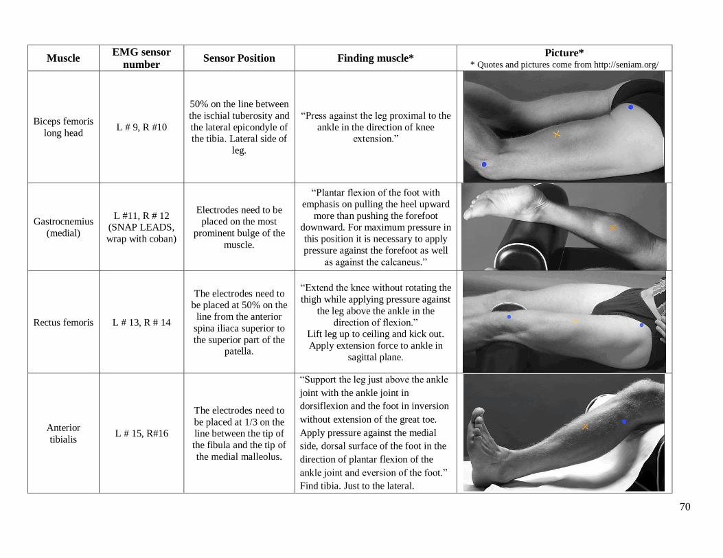
70
Muscle EMG sensor
number Sensor Position Finding muscle*
Picture* * Quotes and pictures come from http://seniam.org/
Biceps femoris
long head L # 9, R #10
50% on the line between
the ischial tuberosity and
the lateral epicondyle of the tibia. Lateral side of
leg.
“Press against the leg proximal to the
ankle in the direction of knee extension.”
Gastrocnemius
(medial)
L #11, R # 12 (SNAP LEADS,
wrap with coban)
Electrodes need to be
placed on the most
prominent bulge of the
muscle.
“Plantar flexion of the foot with
emphasis on pulling the heel upward
more than pushing the forefoot downward. For maximum pressure in
this position it is necessary to apply
pressure against the forefoot as well
as against the calcaneus.”
Rectus femoris L # 13, R # 14
The electrodes need to be placed at 50% on the
line from the anterior
spina iliaca superior to
the superior part of the patella.
“Extend the knee without rotating the
thigh while applying pressure against
the leg above the ankle in the
direction of flexion.” Lift leg up to ceiling and kick out.
Apply extension force to ankle in
sagittal plane.
Anterior
tibialis L # 15, R#16
The electrodes need to
be placed at 1/3 on the line between the tip of
the fibula and the tip of
the medial malleolus.
“Support the leg just above the ankle
joint with the ankle joint in
dorsiflexion and the foot in inversion
without extension of the great toe.
Apply pressure against the medial
side, dorsal surface of the foot in the
direction of plantar flexion of the
ankle joint and eversion of the foot.”
Find tibia. Just to the lateral.

71
20. Place reflective markers on body. Wrap coban under segment markers. Hold up
exoskeleton for placement of pelvic markers before placing PSIS and ASIS.
R Acrom - L Acrom: cm
A. Pelvis (LASIS - RASIS): cm P. Pelvis (LPSIS-RPSIS): cm
R ASIS-R Med Knee: cm L ASIS-L Med Knee: cm
R ASIS-R Lat Knee: cm L ASIS-L Lat Knee: cm
R Knee (Med - Lat Con): cm L Knee (Med - Lat Con): cm
R Lat Knee-R Lat Mal: cm L Lat Knee-L Lat Mal: cm
R Ank (Med - Lat Mal): cm L Ank (Med - Lat Mal): cm
R 5MT-R Toe: cm L 5MT-L Toe: cm
R Heel-R Toe
(wrap lat under mal):
cm L Heel-L Toe
(wrap lat under mal):
cm
R Heel-R 5MT
(wrap lat under mal):
cm L Heel-L 5MT
(wrap lat under mal):
cm
a: ___________ cm (directly vertical L iliac crest to
L_IC)
b: ___________ cm (directly vertical R iliac crest to
R_IC)
c: ___________ cm (L_IC to L GTroch)
d: ___________ cm (R_IC to R GTroch)
e: ___________ cm (L ASIS to L GTroch)
f: ___________ cm (R ASIS to R GTroch)
g: ___________ cm (L_IC to L ASIS)
h: ___________ cm (R_IC to R ASIS)
ASI
Iliac
b a
c d
e f
g h
GTroc
h
IC
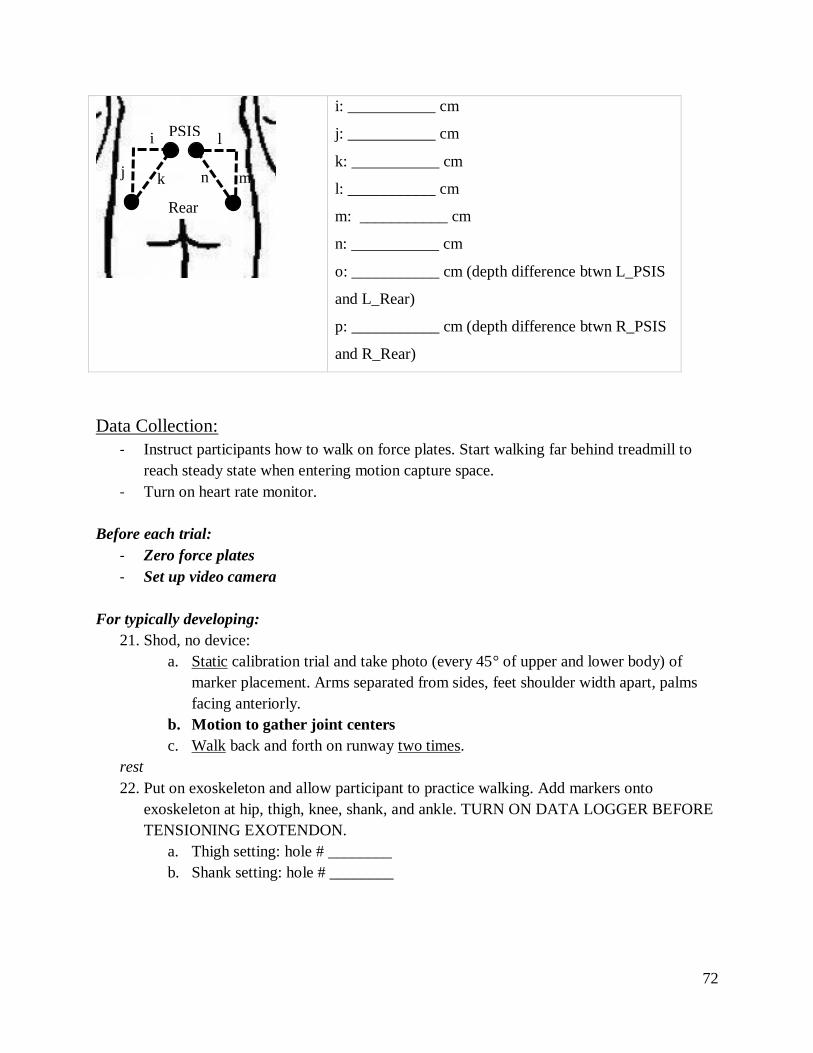
72
i: ___________ cm
j: ___________ cm
k: ___________ cm
l: ___________ cm
m: ___________ cm
n: ___________ cm
o: ___________ cm (depth difference btwn L_PSIS
and L_Rear)
p: ___________ cm (depth difference btwn R_PSIS
and R_Rear)
Data Collection:
- Instruct participants how to walk on force plates. Start walking far behind treadmill to
reach steady state when entering motion capture space.
- Turn on heart rate monitor.
Before each trial:
- Zero force plates
- Set up video camera
For typically developing:
21. Shod, no device:
a. Static calibration trial and take photo (every 45° of upper and lower body) of
marker placement. Arms separated from sides, feet shoulder width apart, palms
facing anteriorly.
b. Motion to gather joint centers
c. Walk back and forth on runway two times.
rest
22. Put on exoskeleton and allow participant to practice walking. Add markers onto
exoskeleton at hip, thigh, knee, shank, and ankle. TURN ON DATA LOGGER BEFORE
TENSIONING EXOTENDON.
a. Thigh setting: hole # ________
b. Shank setting: hole # ________
PSIS i
j k
l
m n
Rear

73
23. With Exoskeleton:
a. Static calibration trial and take photos of marker placement.
b. Two good trials walking trials with each stiffness.
For children with CP:
24. With AFO (baseline):
a. Static calibration trial and take photo of marker placement (if any markers have to
change, such as malleolus)
b. Walk back and forth on runway
rest
25. With AFO + Exoskeleton low stiffness (repeat a. and b. from step 25)

74
rest
26. With AFO + Exoskeleton medium stiffness (repeat b. from step 25)
rest
27. With AFO + Exoskeleton high stiffness (repeat b. from step 25)
rest
28. No AFO and no Exoskeleton (baseline)
a. Static calibration trial and take photo of marker placement (if any markers have to
change, such as malleolus)
b. Walk back and forth on runway
29. No AFO + Exoskeleton low stiffness (repeat a. and b. from step 25)
rest
30. No AFO + Exoskeleton medium stiffness (repeat b. from step 25)
rest
31. No AFO + Exoskeleton high stiffness (repeat b. from step 25)
rest
Post Motion Capture
32. Remove PlayGait, markers, and sensors
33. Interview questions with caregiver and child & survey with child (AUDIO RECORD)
34. Provide reimbursement (check and parking) and toy/stuffed animal. Check number:
_______ Coupon number: __________
After participant leaves
35. Clean up
a. Rub PlayGait and EMG sensors with alcohol prep wipes
b. Rinse heart rate monitor chest strap with water after removing cover plate.
c. Remove tape from markers
36. Save Qualisys data onto thumb drive
a. Export .tsv and .mat after gap filling and applying AIM model
37. Export load cell data to .csv.

75
Appendix D: OpenSim Musculoskeletal Modeling and Simulation
The full-body OpenSim musculoskeletal model developed by Rajogopal 2016 was used
for kinematic analysis (Rajagopal et al. 2016). This model features boney geometry for the full
body. The model has 37 degrees of freedom across the entire body including 6 degrees of
freedom for the pelvis and 7 per leg [1]. To scale the model according to the pipeline in Figure
D-1, we developed a marker set consisting of 62 markers corresponding to the experimental
protocol (Figure D-2). To improve scaling for each participant, anatomical landmark markers on
the elbow, wrist, pelvis, knee, and ankle with a high degree of experimental placement accuracy
were fixed in position for scaling (Table D.1). The No Exo static trials were used to scale the
model for each participant (Table D.2). Scaling adjusts each body segment of the model (hand,
pelvis, etc.) independently to create a subject-specific model that matches experimental data
from the No Exo static trial. The markers on the unscaled model are compared to the
experimental markers, and the distance between the model and experimental markers is
minimized through a weighted least squares algorithm of measurement pairs for each body
segment. Marker weights were specified on a 0 to 20 scale, where zero indicated the
experimental marker had extremely low positional accuracy compared to the markers on the
unscaled model (such as for segment markers placed on the thigh, humerus, and radius) and 20
indicated very high positional accuracy (such as for markers placed on bony landmarks).
Segment marker trajectories experience high displacements due to skin motion artifacts, where
the fleshy skin moves relative to the bone, and thus have low positional accuracy.
As body segments are three-dimensional objects, each segment was scaled independently
in the x, y, and z directions, when possible [2]. When the experimental markers on a body were
not on the same axis, virtual markers were created by projecting the experimental markers along

76
a specific axis, and measurement pairs were then created for markers along this axis. For
instance, when scaling the tibia vertically, it is more accurate to scale based on the knee joint
center and the ankle joint center than using the medial or lateral knee and ankle markers as they
are not aligned vertically. A description of the virtual markers created for static scaling is
provided in Table D.3. Markers placed on bony landmarks have a higher degree of certainty for
positional accuracy, and thus they were weighted higher than markers placed on fleshy body
segments. A sample of scaling factors (Figure D-3), measurement sets (Figure D-4), and marker
weights (Figure D-5) for static scaling is depicted at the end of this Appendix.
Figure D-2: Unscaled Rajagopal model with the
adapted experimental marker set.
Figure D-1: OpenSim data processing pipeline with
models highlighted in dark purple and outputs bolded.

77
Table D.1: Markers fixed in the adapted Rajagopal 2016 model before static scaling for specific subjects.
Marker name
(applies to left and right side of body) Description
HME Medial epicondyle (elbow)
HLE Lateral epicondyle (elbow)
RSP Radial styloid process (wrist)
USP Ulnar styloid process (wrist)
ASIS Anterior superior iliac spine (pelvis)
FLE Lateral femoral epicondyle (knee)
FME Medial femoral epicondyle (knee)
AnkL Lateral malleolus (ankle)
AnkM Medial malleolus (ankle)
Table D.2: Inputs and outputs for each OpenSim process.
OpenSim Process Inputs Outputs
Static Scaling
TRC file of static marker trajectories,
subject weight,
Rajagopal model,
Static marker weights
Subject-specific model
Inverse Kinematics
Subject-specific model,
TRC file of dynamic marker trajectories,
Dynamic marker weights
Joint angles (MOT files)
Table D.3: Description of virtual markers used for static scaling.
Virtual Marker Associated Scale Factor(s) Description
RWJC, LWJC hand Right and left wrist joint centers
RPm, LPm torso_x, torso_y,
thigh_R_y, thigh_L_y
Right and left mid-pelvis (mid in the anterior –
posterior direction)
RSHv, LSHv torso_x, Right and left shoulder
ASIm pelvis_x Mid-point of the right and left ASIS markers
PSIm pelvis_x Mid-point of the right and left PSIS markers
RKJC, LKJC thigh_R_y, thigh_L_y,
tibia_R_y, tibia_L_y Right and left knee joint centers
RAJC, LAJC tibia_R_y, tibia_L_y Right and left ankle joint centers
RATv, LATv foot_x Right and left projection of the toe marker to
the ankle vertical position
RAHv, LAHv foot_x Right and left projection of the heel marker to
the ankle vertical position

78
To generate a model for use with the exoskeleton trials, the OpenSim Scaling Tool was
used to add the 5 additional markers applied on the exoskeleton. Before scaling, all of the
model’s markers that did not change position between the No Exo and Exo conditions were
fixed. The unfixed markers included the left and right ASIS, PSIS, and thigh markers as they
were removed or moved to accommodate wearing the exoskeleton. All scale factors were set to
one to ensure the size of the model would not change, and measurement pairs and marker
weights remained the same to identify the relative position of the additional exoskeleton markers.
Inverse kinematics was run on the No Exo and Exo models using the marker trajectory
data from each walking trial and a different set of marker weights (Figure D-6). Again, weighted
least squares optimization was used to minimize the difference between experimental markers
and the scaled model markers. As this study’s outcome measures focus on hip, knee, and ankle
movement, the bony landmark markers on the pelvis, knee, and foot were weighted highest.
Maximum errors between model and experimental markers are recommended as 2-4 cm [2], but
we saw larger errors in the upper body markers since study participants moved their head
drastically which could not be accommodated by the model’s rigid torso.

79
Figure D-3: Sample scale factors used for static scaling
Figure D-4: Marker pairs used to generate measurement sets

80

81
Figure D-5: Marker weights based on a 0-20 scale for static scaling

82

83
Figure D-6: Sample marker weights on a 0-20 scale for inverse kinematics
References:
[1] Rajagopal, A., C. L. Dembia, M. S. DeMers, D. D. Delp, J. L. Hicks and S. L. Delp (2016).
"Full-body musculoskeletal model for muscle-driven simulation of human gait." IEEE
Transactions on Biomedical Engineering 63(10): 2068-2079.
[2] OpenSimVideos (2017). OpenSim Webinar: Tips and Tricks for Data Collection, Scaling and
Inverse Kinematics in OpenSim, YouTube.

84
Appendix E: Inverse Kinematics and Correlation Plots for all Conditions
TD1

85
No Exo
Exo Low
Exo Med
Exo High

86
TD 2

87
No Exo
Exo Low
Exo Med
Exo High

88
TD3

89
No Exo
Exo Low
Exo Med
Exo High

90
H1

91
No Exo
Exo Low
Exo Med
Exo High

92
H2

93
No Exo
Exo Low
Exo Med
No Exo High data

94
Appendix F: Electromyography Results
TD1 – Right Leg

95
TD1 – Left Leg

96
TD2 – Right Leg

97
TD2 – Left Leg

98
TD3 – Right Leg

99
TD3 – Left Leg

100
H1 – Right Leg

101
H1 – Left Leg

102
H2 – Right Leg
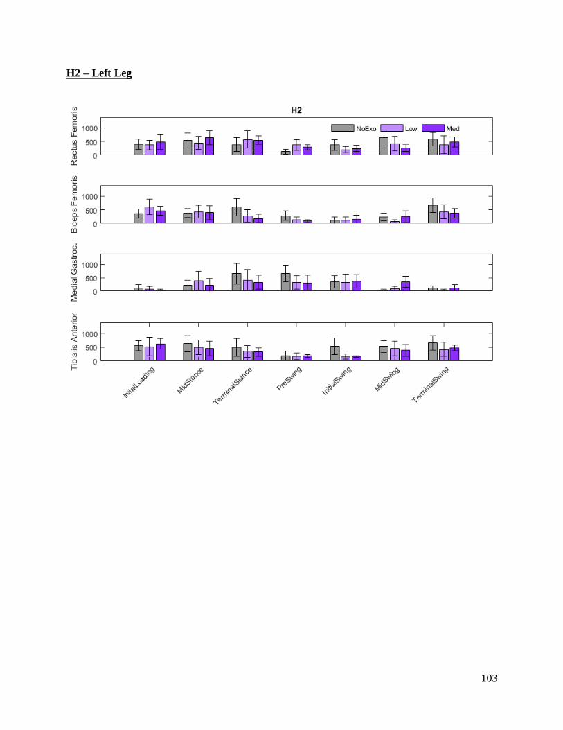
103
H2 – Left Leg