Embed Size (px)
Citation preview

16
A Performance Model for Integrated Layer Processing*
Bengt Ahlgren Swedish Institute of Computer Science Box 1263, S-164 28 Kista, Sweden E-mail: [email protected]
Abstract Integrated Layer Processing is an implementation technique for data manipulation functions in communication protocols. The purpose of this technique is to increase communication performance. It reduces the number of memory accesses and thus relieves the memory bandwidth bottleneck. Integrated Layer Processing can however, in some situations, substantially increase the number of memory accesses, and therefore instead reduce performance. The main reason is contention for processor registers.
We present a performance model that captures the memory behavior of data manipulation functions for both integrated and sequential implementations. By comparing the model to measurements of real and synthetic data manipulation functions, we show that the model accurately predicts the performance. The model can be used to assess whether an integrated implementation will perform better or worse than a sequential implementation. The situations where integration would reduce performance can then be avoided without spending a lot of effort on a more complex integrated implementation.
Keywords ILP, Integrated Layer Processing, performance modeling, protocol implementation techniques
'This work is supported in part by the CEC DO III Esprit LTR project 21926 HIPPARCH.
A. Tantawy (ed.), High Performance Networking VII© Springer Science+Business Media Dordrecht 1997
250 Part Six Architectural Issues
1 INTRODUCTION
The communication performance of workstation class computers is limited by the performance of their primary memory system (Druschel, Abbott, Pagels and Peterson, 1993; Smith and Traw, 1993). The reason is that software implementation of protocol data manipulation, such as checksum calculation, needs to access every byte of message data in memory. Since the access time of memory chips are decreasing at a much slower pace than CPU speeds are increasing (Patterson and Hennessy, 1994; Wulf and McKee, 1995), the bottleneck is getting more and more severe relative to the CPU performance of future computer systems.
Integrated Layer Processing, ILP, is an implementation technique for data manipulation functions in communication protocols presented by Clark and Tennenhouse (1990). The purpose with ILP is to relieve the memory bottleneck by reducing the number of memory accesses for message data and thus increase communication performance. The potential reduction comes from combining the manipulation functions of several protocol layers into a pipeline in a single processing loop. For each iteration of the loop the manipulations are run in succession on a small quantity of data, typically a word or a couple of words. Message data is pipelined via registers between the manipulations and need not be accessed from memory by each function.
ILP has been shown to considerably improve throughput of simple functions (Abbott and Peterson, 1993; Gunningberg, Partridge, Sirotkin and Victor, 1991; Partridge and Pink, 1993) and to improve throughput less for more complicated functions and when used in complete systems (Braun and Diot, 1995; Gunningberg, Partridge, Sirotkin and Victor, 1991).
In a previous paper (Ahlgren, Bjorkman and Gunningberg, 1996) we have shown that ILP also can substantially decrease performance compared to a conventional sequential implementation. The conclusion in that paper was that the use of CPU registers play a very important role for the performance gain, or loss, for an integrated implementation compared to a sequential. We found that when the aggregated state size of the data manipulation functions does not fit in processor registers, the integrated implementation quickly becomes much slower than the sequential implementation.
In this paper we continue to study the performance behavior of integrated and sequential implementations of data manipulation functions . Since the purpose of ILP is to reduce the number of memory accesses, we are particularly interested in the memory behavior and the role of the CPU registers. We present a performance model that predicts the performance of the two implementation techniques. The model calculates the number of clock cycles per message byte given a set of architecture parameters and a set of function parameters describing the computer system and the data manipulation functions, respectively. We show that the predicted performance from the model compare well with measurements.
The important contribution of our performance model is that it does not only consider memory accesses for message data, but also memory accesses for function state that does not fit in processor registers.
The motivation behind this work is to fully understand how different parameters affect the performance of the two implementation techniques. This knowledge can be useful for tools ("ILP compilers" (Braun and Diot, 1996b» that automatically generate integrated implementations.
A performance model for integrated layer processing 251
(]I
0~ad f ~ite j I output buffer
mput buffer
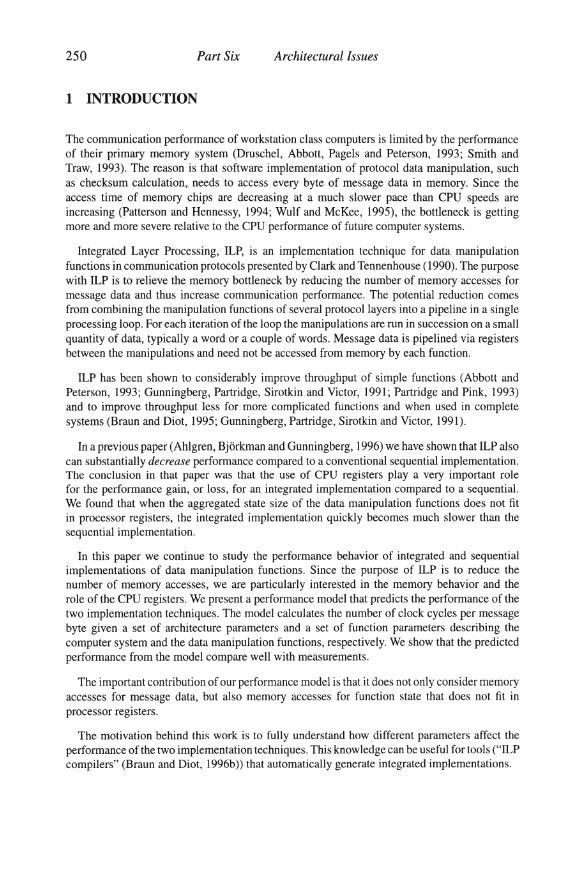
Figure 1 A data manipulation function "f".
2 RELATED WORK
We have studied Integrated Layer Processing using a technique with synthetic data manipulation functions. These results are presented in a previous paper (Ahlgren, Bjorkman and Gunningberg, 1996). We concluded that the key factor is whether the aggregated function state fits in the available CPU registers or not. We showed experimentally that an integrated implementation can be slower than the corresponding sequential.
Abbott and Peterson (1993) also recognizes that "the key limiting factor is register pressure" when the number of integrated functions is increased. They also predict that the integrated implementation can be slower than the sequential but do not show it analytically or verify it experimentally. They present a performance model, but it only includes memory references to message data. In their model, the integrated implementation is therefore always faster than the sequential implementation. We compare our model with their model in a later section of this paper.
Integrated Layer Processing has also been studied by a number of other researchers (Braun and Diot, 1995; Braun and Diot, 1996a; Gunningberg, Partridge, Sirotkin and Victor, 1991). They have however not presented any performance model for comparing an integrated implementation with a sequential.
Previous work have paid quite a lot of attention to the practical problem of applying ILP to a real protocol stack (Abbott and Peterson, 1993; Braun and Diot, 1996a). We are aware of these problems but do not address them in our work. These problems are independent of whether integration as such has the potential of producing a faster implementation for a specific set of data manipulation functions or not.
3 DATA MANIPULATION FUNCTIONS AND ILP
Communication protocol processing can be divided in two parts: protocol control and data manipulation. The protocol control part processes the information in message headers and maintains the state needed by the protocol, for example, connection state. The control processing is usually specified and implemented as a finite state machine. The data manipulation part processes the data part of the messages. Examples of data manipulation functions are checksums, encryption and presentation encoding. They all have in common that they process each byte of the message data and possibly produce new data. This is illustrated in Figure 1. The data to be manipulated is stored in buffers. The input and output buffers are often the same buffer in a real implementation, but to be more general we illustrate them as separate buffers. The data manipulation function f is implemented as a loop which reads a block of data from the input
252 Part Six
I input buffer
~ad
~~ad ~
~~i' lJl ~ite ! I output buffer
Architectural Issues
II
h
h
input buffer
~~~d
1 ~i~lte ___ ~~_ . output buffer
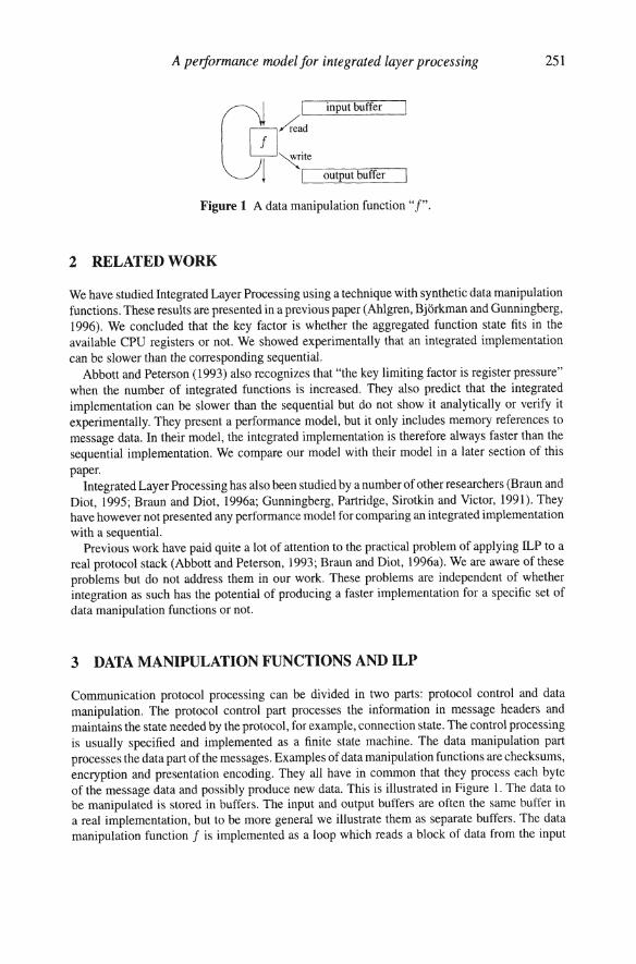
Figure 2 Composition of data manipulation functions, sequential (left) and integrated (right).
buffer, computes the function value and writes the result to the output buffer. The minimum size of the block depends on the function .
3.1 Sequential vs. integrated implementations
In a traditional implementation of a protocol stack, the data manipulation functions are executed independently in their respective layer, as illustrated to the left in Figure 2. We call this implementation a sequential implementation. Each function follows sequentially and reads and, possibly, writes all data in the buffer. The functions need not be immediately adjacent as in the figure. They can even be located in different address spaces. An example of this is the implementation of the TCPIIP protocol stack with an RPC protocol in a typical Unix system. It has presentation layer encoding in the application and the UDP or TCP checksum in the operating system kernel.
The idea with Integrated Layer Processing (Clark and Tennenhouse, 1990) is to combine the data manipulation functions of several protocol layers into one processing loop as illustrated to the right in Figure 2. The purpose is to avoid reading and writing the message data in the buffers several times. The performance gain has shown to be substantial (Abbott and Peterson, 1993). We call this implementation an integrated implementation. It reads a block of data from the input buffer and applies all functions in succession on the data. The assumption is that the transformed data is stored in processor registers between the functions and need not be accessed from memory by each function. After the last manipulation function the resulting block of data is written to the output buffer and the loop continues with the next block until the input buffer is finished . In this particular example with three functions each producing new data, the number of memory accesses for message data is reduced to t of the sequential implementation.
3.2 Characterizing data manipulation functions
Before we can develop the model explaining and predicting the behavior of an integrated implementation compared to a sequential implementation, we first need a way to describe the
A performance model for integrated layer processing 253
data manipulation functions at a suitable level of abstraction. Since the purpose with an integrated implementation is to save memory accesses, we must capture the characteristics that define the memory behavior of the function.
The following paragraphs describe the parameters we have identified as relevant.
Input data block The size of the input block is fundamental to a data manipulation function. The whole block must be present in order to do the processing. The function processes one block of data in each iteration. For example, the TCPIIP checksum has an input block size of 2 bytes, the DES encryption has 8 bytes and the MD-5 message digest has 16 bytes.
Output data block Depending on the particular function, the size of the output data block may be the same, less than or greater than the size of the input data block. A data compression function is an example of a function that produces less data than input. Some functions, like checksums, do not produce output data at all.
State Many data manipulation functions keep a state between iterations. This is the case for the TCPIIP checksum and the DES encryption algorithm in CBC mode. The checksum algorithm adds a 16 bit data block to the accumulated sum of previous blocks, i.e., the sum is the state. The state need to be stored somewhere-preferable in registers, since it is accessed for each iteration. The size of the state is therefore important for the memory behavior of the function . The final state is usually the result of functions that do not produce output data.
Constants Data manipulation functions can use constant values in its computation. A constant is explicit in the code and is accessed at least once per loop iteration. A constant is therefore a candidate for register allocation by the compiler. As such, constants compete for register space with the function state. A difference is that constants in memory need only be read, while the state is updated and must be both read and written. A constant can however be used more than once, so the compiler must analyze the number of references to be able to make a good register allocation.
Table look-ups Tables are similar to constants in that they contain constant values. The difference is that only a fraction of the entries in a table are accessed for each iteration. A table is also usually too large for the processor registers and must therefore be accessed from memory. The interesting parameters are the number of table lookups per iteration and the size of the table.
Temporaries A data manipulation function will use a number of temporary variables for intermediate results. The temporaries need not be explicit in the original source code. The compiler usually puts temporary variables in registers.
Instructions We distinguish between three logical categories of machine level instructions: computation, memory and loop overhead. The computation instructions are arithmetic-logic and control instructions used to compute the state or the output data of the data manipulation function. The memory instructions transfer data between the CPU registers and the memory or the cache. The loop overhead instructions consist of instructions for incrementing the buffer pointers, decrementing and testing the loop variable and a conditional branch back to the beginning of the loop.
The particular machine instructions and the number of them in an implementation depend both on the machine architecture and the compiler used to produce the code. The computation instructions, however, are pretty well defined by the data manipulation function. The number of memory instructions depend on register allocation, except for the accesses to the input and output data buffers which always are referenced in memory. The loop overhead instructions depend mainly on the processor instruction set, but also on the compiler.
254 Part Six Architectural Issues
Table 1 Model parameters.
Architecture parameters
R number of available CPU registers (word size) Ac access time of first level cache (clocks/word) AM access time of memory (clocks/word) CPt cycles per instruction L loop overhead (instructions/loop) C CPU clock frequency W word size (bytes)
Function parameters
n number of functions Si state size for function i (words) ai computation instructions for function i per input block bl" input block size for function i (bytes) b~ut output block size for function i (0 if no output)
4 THE PERFORMANCE MODEL
In this section we present a performance model for data manipulation functions. The model computes the cost in time per data byte both for an integrated implementation and for a sequential implementation of the same combination of data manipulation functions. The costs of the implementations can then be compared to see which performs best.
4.1 Model parameters
Table I lists the input parameters ofthe model. The parameters are of two kinds. The architecture parameters specify the characteristics of the target computer system. The function parameters specify the characteristics of the desired data manipulation functions.
The number of CPU registers (R) denotes the number of registers that the compiler has available for the function state. This parameter is thus compiler dependent in addition to being CPU dependent. We assume that this number is invariant when the other parameters of the model are varied. The memory access time (AM) is the average access time for reading and writing memory sequentially through the cache(s) of the system. The effects of cache line fills and cache line write-backs are included in this average. We assume that the read and the write access times are the same.
The CPl parameter models the superscalarity of the system. A superscalar processor can execute more than one instruction in a single clock cycle. Non-superscalar processors have CPf ~ I. Superscalar processors can have CPl < I, but the value is usually very dependent on the mix of instructions.
The loop overhead (L) depends on the instruction set of the CPU, but can also depend on the compiler. As defined in the previous section, the loop overhead consist of incrementing two buffer pointers (or one pointer for checksum-like functions), decrementing and testing the loop variable, and a conditional branch back to the beginning of the loop.
To make the model as simple as possible, yet still capturing the desired behavior, we have

A peifonnance model for integrated layer processing 255
chosen to not include constants and tables of the function parameters described in the previous section. We believe that this does not significantly affect the modeled memory behavior of the respective implementation techniques. The constants have almost the same influence on the memory behavior and total performance as the function state has, since the constants also compete for the available registers and overflows on the stack. The tables add a random component of scattered memory accesses which is very similar, if not identical, for both implementation techniques.
Another limitation in the model is the selection of the output block size. A function must either not produce output at all (checksum-like functions), or produce the same amount of output as input, i.e., the output block size must be the same as the input block size.
4.2 Model formulas
The purpose of the performance model is to accurately model the register, cache and memory behavior ofthe integrated and sequential implementations of a set of data manipulation functions . The number of memory accesses are therefore central in the model. There are two kinds: accesses for message data, denoted DA (data accesses), and accesses for function state, denoted SA (state accesses). Both of these are expressed as the number of word accesses (load or store) per byte of message data. DA for the integrated case is simply:
(1)
that is, one load and one store for each word of data. We here assume that there is at least one function producing new data. We also assume that functions with a block size that is less than the word size still can read and write data a word at a time.
In the sequential case we have to add the loads and stores for each function:
DA SEQ = ~ x ~ ( W' = 0 : 1) W ~ bOu, > 0 : 2
1= 1 t
(2)
If b1u, is zero, the function only reads the message data (I access). Otherwise it writes as well (2 accesses).
The number of state accesses for the integrated implementation is:
SA1LP = - X -2 \ SILP < R : 0
bILP SILP > R : SILP - R (3)
The important factor in this equation is the parameter R, the number of CPU registers available for function state, and its relationship to SILP, which is the aggregated state of all functions:
n
SILP = LSi i ::;:; l
(4)
If the whole state fits in the registers, there are no memory accesses. Otherwise, part of the state has to be stored in memory. This is the key behavior of the model that is expressed by Equation 3.
256 Part Six Architectural Issues
We assume that the state in memory has to be loaded from and stored back to memory once per iteration of the ILP loop, thus the "2" in the numerator of the fraction in Equation 3. bILP in the denominator is the block size common for all functions in the integrated implementation. It is the least common mUltiple of the block sizes of all manipulation functions:
(5)
The SA formula for the sequential implementation is a sum over the functions:
SEQ ~ ( 2 {Si :s: R : 0 ) SA =L.. ~ x i= I bin Si > R : Si - R
(6)
The expression inside the sum is essentially the same as for the integrated case, but the state and block sizes are for the respective original functions instead of for the integrated function .
Equations 3 and 6 simplify the case where there is a function whose state alone overflows the registers. The model assumes that the code can be arranged so that only one load and one store are required for each word of overflowed state. This is not true for all functions. It depends on the specific details of the function algorithm. For functions where more memory accesses than one load and one store are necessary, the model underestimates the number of accesses. The underestimation may be larger, but never less, for the integrated implementation compared to the sequential, because the overflowed state in the former is never smaller than the overflowed state of any individual function in the latter.
The message data and state accesses just defined can either be satisfied by the processor cache or the real memory. We assume that the state accesses will always be present in the first level cache of the processor. This is a reasonable assumption, since the state is accessed on every iteration of the loop. The message data is on the other hand not always present in the cache. We are therefore interested in both the case when data are present in the (first level) cache and the case when data has to be fetched from memory. The behavior of a real system will be somewhere in between. Below we present one formula each for these two cases. The formulas are used for both the sequential and integrated cases with the respective substitution of the above defined formulas for DA and SA.
The number of clock cycles per byte of message data in the cached case is:
clocks (cached) = ePl x (~~~ + La) + Ae x (DA + SA) (7)
The second term is the time to access the message data and the state from the cache (Ae is the cache access time parameter). The first term is the number of clock cycles for the non-memory instructions. The sum is the number of computation instructions per byte for all functions. La is the number of instructions of loop overhead. It is computed with the following formulas :
ILP L La = bILP
LOSEQ = ~ L L.. bIn i = 1 t
(8)
(9)
A perfonnance model for integrated layer processing 257
The sum of the computation instructions and the loop overhead is then multiplied by CPI, the cycles per instruction parameter, to get the time to execute all instructions. The total formula then represents the number of clock cycles to execute the instructions and access the memory.
The non-cached, or memory, case is similar to the cached case, but the data accesses are multiplied by AM, the memory access time:
clocks (memory) = CPI x (~ ~~ + LO) + AM x DA + Ac x SA (10)
Finally, if the time in seconds is desired instead of clock cycles, the number of clock cycles are divided by the CPU clock frequency:
clocks time per byte = -----c-
5 COMPARISON WITH MEASURED RESULTS
(11)
In this section we compare the modeled performance to the measurements from a previous paper (Ahlgren, Bjorkman and Gunningberg, 1996). In that paper we measured the performance of integrated and sequential implementations of "synthetic" data manipulation functions . The synthetic functions are generated from the same set of function parameters as we use in the model. The synthetic implementations process data and use memory and registers according to the parameters, but does not produce any "useful" output. Synthetic functions makes it easy to study the behavior when one parameter (e.g., the size of the state) is varied and all other parameters are kept constant.
5.1 The Abbott & Peterson loop
The first comparison is both with a real implementation of the BSWAP/PES/CKSUM function combination used by Abbott and Peterson (1993) (see their Figure 2) and with a synthetic implementation with the same characteristics. The BSWAP/PES/CKSUM loop consists of a byteswap, a "pseudo-encryption" and the Internet checksum. We have made one change to their original integrated implementation. We use a block size of two words which saves the "if' statement and gives better performance. We discuss the block size further in Section 6.
Table 2 presents the measured performance of the real and synthetic implementations compared with the modeled performance for three computer systems. The modeled performance values compare well to the measured real implementation for all three systems. The largest deviation is about 10 % (for the HP, sequential with warm cache). Tables 3 and 4 lists the model parameters used in the comparison.
The available CPU registers have been determined by looking at the machine code produced by the respective compilers from synthetic functions with varying state size. The compilers used are the stock "cc" compilers for both operating systems (SunOS 4.l.x and HP-UX A.9.5). The SunOS compiler is not particularly good at register allocation. The value of the register parameter therefore varies with the situation.
Of the memory access figures, the value for the SPARCstation 2 is calculated from the actual memory access time. For the SPARCstation 20171, the value is calculated from the maximum
258 Part Six Architectural Issues
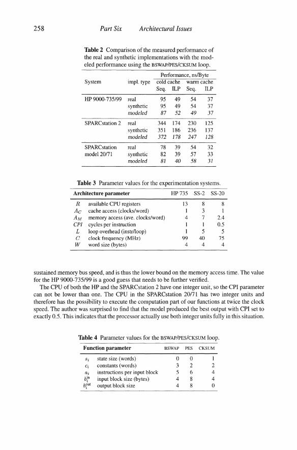
Table 2 Comparison of the measured performance of the real and synthetic implementations with the mod-eled performance using the BSWAP/PES/CKSUM loop.
Performance, ns/Byte System imp\. type cold cache warm cache
Seq. ILP Seq. ILP
HP 9000-735/99 real 95 49 54 37 synthetic 95 49 54 37 modeled 87 52 49 37
SPARCstation 2 real 344 174 230 125 synthetic 351 186 236 137 modeled 372 178 247 128
SPARCstation real 78 39 54 32 model 20171 synthetic 82 39 57 33
modeled 81 40 58 31
Table 3 Parameter values for the experimentation systems.
Architecture parameter HP735 SS-2 SS-20
R available CPU registers 13 8 8 Ac cache access (clocks/word) 3 1 AM memory access (ave. clocks/word) 4 7 2.4 ePi cycles per instruction I I 0.5 L loop overhead (instr/loop) I 5 5 C clock frequency (MHz) 99 40 75 W word size (bytes) 4 4 4
sustained memory bus speed, and is thus the lower bound on the memory access time. The value for the HP 9000-735/99 is a good guess that needs to be further verified.
The CPU of both the HP and the SPARCstation 2 have one integer unit, so the CPI parameter can not be lower than one. The CPU in the SPARCstation 20171 has two integer units and therefore has the possibility to execute the computation part of our functions at twice the clock speed. The author was surprised to find that the model produced the best output with CPI set to exactly 0 .5. This indicates that the processor actually use both integer units fully in this situation.
Table 4 Parameter values for the BSWAP/PES/CKSUM loop.
Function parameter BSWAP PES CKSUM
Si state size (words) 0 0 I Ci constants (words) 3 2 2 ai instructions per input block 5 6 4 bin
t input block size (bytes) 4 8 4
bout t output block size 4 8 0

A performance model for integrated layer processing 259
150
50
Message data accessed lrom cache
Sequential, modeled .• " Integrated, modeled --". equential, measured -
Integrated, measured ---
Siale size (words)
Message data accessed from memory
200 r-~-~~-~~-~~-~-,
Sequential, modeled . + .. Integrated. modeled .. >< ••
equenlial, measured -Integrated. measured ----
I 100 r----~_-/
50
Stale size (words)
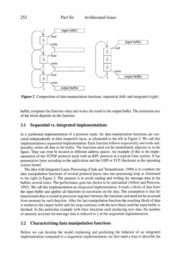
Figure 3 Comparison of measured performance with modeled performance for the HP 9000-735/99.
As previously mentioned, for simplicity we chose not to include the constants parameter in the model. It does not affect the result in this case, because all of the state and the constants fits in the available registers. But it leads to a weakness in the comparison. Since the state fits in the registers, the register exhaustion part of the model is not exercised. In the next section we therefore also compare with synthetic loops with varying state sizes.
5.2 Synthetic loops
The second comparison is with measurements of synthetic data manipulation functions on the HP 9000-735/99. We have varied the state size and the number of functions. The other function parameters have been kept constant: 3 functions, 4 byte input and output block sizes and 10 computation instructions per input block. The architecture parameters used are those for the HP in Table 3.
As can be seen in Figure 3, the measured and modeled performance correspond very well. We can see that the model captures the register exhaustion just as intended for the integrated implementation when the state size grows above 4 words. For a state size of 5 words, the aggregated state is 3 x 5 = 15 words, which does not fit in the available 13 registers.
6 MODEL ANALYSIS
How do different factors affect the performance of an integrated implementation compared to a sequential? In this section we will discuss the role of the parameters in the model and how they affect the performance of the two implementation techniques.
6.1 Abbott and Peterson's model
But first we compare the performance model with the model presented by Abbott and Peterson (1993) (see Figure 4). Their model computes the number of clock cycles for loop overhead, computation and data accesses. This basic structure is very similar to our model. We also count
260 Part Six Architectural Issues
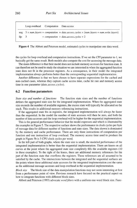
Loop overhead Computation Data access
seq: 3 x num-Layers + computation + datallCCesLcycles x (num_layers + num_writLlayers)
ilp: 3 + computation + datallccessJ:ycles x 2
Figure 4 The Abbott and Peterson model, estimated cycles to manipulate one data word.
the cycles for loop overhead and computation instructions. If we set the CPI parameter to I, we basically get the same result. Both models also compute the cost for accessing the message data.
The main difference is that their model does not include memory accesses for function state. It can therefore not be used to study the situation we are interested in when the aggregated function state does not fit in the processor registers. As a consequence, in their model the integrated implementation always performs better than the corresponding sequential implementation.
Another difference is that we have chosen to have separate expressions for the cached and non-cached cases, whereas they capture cache access time, cache hit rate and memory access time in one parameter (data_accesLcycles).
6.2 Function parameters
State size and number of functions The function state sizes and the number of functions defines the aggregated state size for the integrated implementation. When the aggregated state size exceeds the number of available registers, the excess state will typically be allocated on the stack. This results in additional memory referencing instructions.
If the aggregated state fits in registers, the integrated implementation will always be faster than the sequential. In the model the number of state accesses will then be zero, and both the number of data accesses and the loop overhead will be higher for the sequential implementation.
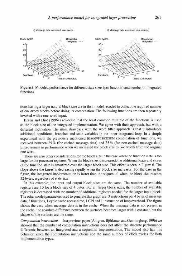
This is the general performance behavior that the model expresses and which is illustrated by the examples in Figure 5. The respective surface shows the performance in clock cycles per byte of message data for different number of functions and state sizes. The data shown is dominated by the memory and cache performance. There are only three instructions of computation per function and one instruction of loop overhead. The memory access time used to produce the graph in Figure 5b is 5 CPU clock cycles per word.
In the left part of both graphs, where the state size is small, the modeled performance of the integrated implementation is better than the sequential implementation. There are knees on all curves at the point where the aggregated state size completely fills the available registers (10 in these examples). To the right of the knees, there are additional memory references for the part of the function state that overflows the registers. These references are all assumed to be satisfied by the cache. The intersections between the integrated and the sequential surfaces are the points where these additional state accesses for the integrated implementation cost the same as the additional message accesses and loop overhead in the sequential implementation.
Block size The block size of the data manipulation functions may not seem interesting at first from a performance point of view. Previous research have focused on the practical aspect on how to integrate functions with different block sizes.
Abbott and Peterson (1993) advocate word filters with a uniform one-word block size. Func-
A performance model for integrated layer processing
a) Message data accessed from cache b) Message data accessed from memory
Clock cycles
40
30
20
10
50
Functions
Sequential -Integrated
15
State size (words) o State size (words)
261
Figure 5 Modeled performance for different state sizes (per function) and number of integrated functions.
tions having a larger natural block size are in their model recoded to collect the required number of one-word blocks before doing its computation. The following functions are then repeatedly invoked with a one-word input.
Braun and Diot (1996a) advocate that the least common multiple of the functions is used as the block size of the integrated implementation. We agree with their approach, but with a different motivation. The main drawback with the word filter approach is that it introduces additional conditional branches and state variables in the inner integrated loop. In a simple experiment with the previously mentioned BSWAP/PES/CKSUM combination of functions, we received between 25 % (for cached message data) and 35 % (for non-cached message data) improvement in performance when we increased the block size to two words from the original one word.
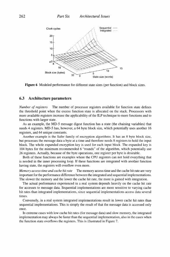
There are also other considerations for the block size in the case when the function state is too large for the processor registers. When the block size is increased, the additional loads and stores of the function state is amortized over the larger block size. This effect is seen in Figure 6. The slope above the knees is decreasing rapidly when the block size increases. For the case in the figure, the integrated implementation is faster than the sequential when the block size reaches 32 bytes, regardless of state size.
In this example, the input and output block sizes are the same. The number of available registers are 10 for a block size of 4 bytes. For all larger block sizes, the number of available registers is decreased with the number of additional registers needed for the larger input block. The other model parameters used to generate this graph are: 3 instructions per 4 bytes of message data, 3 functions, 1 cycle cache access time, 1 CPI and 1 instruction of loop overhead. The figure shows the case when message data is in the cache. When the message data is not present in the cache, the absolute difference between the surfaces becomes larger with a constant, but the shapes of the surfaces are the same.
Computation instructions In a previous paper (Ahlgren, Bjorkman and Gunningberg, 1996) we showed that the number of computation instructions does not affect the absolute performance difference between an integrated and a sequential implementation. The model also has this behavior, since the computation instructions add the same number of clock cycles for both implementation types.
262 Part Six Architectural Issues
Clock cycles Sequential -Integrated
20
15
10
5
15
Block size (bytes) 0 State size (words)
Figure 6 Modeled performance for different state sizes (per function) and block sizes.
6.3 Architecture parameters
Number of registers The number of processor registers available for function state defines the threshold point when the excess function state is allocated on the stack. Processors with more available registers increase the applicability of the ILP technique to more functions and to functions with larger state.
As an example, the MD-5 message digest function has a state (the chaining variables) that needs 4 registers. MD-5 has, however, a 64 byte block size, which potentially uses another 16 registers, and 64 unique constants.
Another example is the Safer family of encryption algorithms. It has an 8 byte block size, but processes the message data a byte at a time and therefore needs 8 registers to hold the input block. The whole expanded encryption key is used for each input block. The expanded key is 104 bytes for the minimum recommended 6 "rounds" of the algorithm, which potentially use 26 registers. Actually, because of the byte operations, one register per byte is desirable.
Both of these functions are examples where the CPU registers can not hold everything that is needed in the inner processing loop. If these functions are integrated with another function having state, the registers will overflow even more.
Memory access time and cache hit rate The memory access time and the cache hit rate are very important for the performance difference between the integrated and sequential implementations. The slower the memory and the lower the cache hit rate, the more is gained with integration.
The actual performance experienced in a real system depends heavily on the cache hit rate for accesses to message data. Sequential implementations are more sensitive to varying cache hit rates than integrated implementations, since sequential implementations access data several times.
Conversely, in a real system integrated implementations result in lower cache hit rates than sequential implementations. This is simply the result of that the message data is accessed only once.
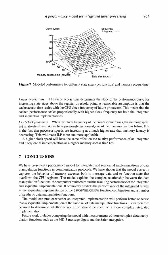
In extreme cases with low cache hit rates (for message data) and slow memory, the integrated implementation may always be faster than the sequential implementation, also in the cases when the function state overflows the registers. This is illustrated in Figure 7.
A performance model for integrated layer processing
Clock cycles
40
o
Sequential -Integrated .
15
State size (words)
263
Figure 7 Modeled performance for different state sizes (per function) and memory access time.
Cache access time The cache access time determines the slope of the performance curve for increasing state sizes above the register threshold point. A reasonable assumption is that the cache access time scales with the CPU clock frequency of future processors. This means that the cached performance scales proportionally with higher clock frequency for both the integrated and sequential implementations.
CPU clockfrequency When the clock frequency of the processor increases, the memory speed get relatively slower. As we have previously mentioned, one of the main motivations behind ILP is the fact that processor speeds are increasing at a much higher rate than memory latency is decreasing. This will make ILP more and more applicable.
A higher clock speed will have the same effect on the relative performance of an integrated and a sequential implementation as a higher memory access time has.
7 CONCLUSIONS
We have presented a performance model for integrated and sequential implementations of data manipulation functions in communication protocols. We have shown that the model correctly captures the behavior of memory accesses both to message data and to function state that overflows the CPU registers. The model explains the complex relationship between the data manipulation functions, the computer architecture and the resulting performance of the integrated and sequential implementations. It accurately predicts the performance of the integrated as well as the sequential implementation of the BSWAP/PES/CKSUM function combination and a number of synthetic data manipulation functions .
The model can predict whether an integrated implementation will perform better or worse than a sequential implementation of the same set of data manipulation functions . It can therefore be used to determine whether or not effort should be spent on a more complex integrated implementation.
Future work includes comparing the model with measurements of more complex data manipulation functions such as the MD-5 message digest and the Safer encryption.
264 Part Six Architectural Issues
ACKNOWLEDGMENTS
The author wishes to thank Per Gunningberg and Mats Bjorkman for the discussions during the development of the model and for comments on drafts of this paper.
The author also thanks the anonymous reviewers for valuable comments.
REFERENCES
Abbott, M.B. and Peterson, L.L. (1993) Increasing network throughput by integrating protocol layers. IEEEIACM Transactions on Networking, 1(5):600-610, October.
Ahlgren, B., Bjorkman, M. and Gunningberg, P. (1996) Integrated layer processing can be hazardous to your performance. In IFfP Protocols for High Speed Networks , Sophia-Antipolis, France, October 28-30.
Braun, T. and Diot, C. (1995) Protocol implementation using integrated layer processing. In SIGCOMM '95 Conference Proceedings, pages 151-161, Cambridge, MA, USA, August 28-September 1. ACM SIGCOMM Computer Communication Review, 25(4).
Braun, T. and Diot, C. (1996a) Performance evaluation and cache analysis of an ILP protocol implementation. IEEEIACM Transactions on Networking, 4(3) :318-330, June.
Braun, T. and Diot, C. (1996b) Automated code generation for integrated layer processing. In IFIP Protocols for High Speed Networks, Sophia-Antipolis, France, October 28-30.
Clark, D.D. and Tennenhouse, D.L. (1990) Architectural considerations for a new generation of protocols. In SIGCOMM '90 Conference Proceedings, pages 200-208, Philadephia, Pennsylvania, September 24-27. ACM SIGCOMM Computer Communication Review, 20(4).
Druschel, P., Abbott, M.B., Pagels, M.A. and Peterson, L.L. (1993) Network subsystem design. IEEE Network, 7(4):8-17, July.
Gunningberg, P. , Partridge, c., Sirotkin, T. and Victor, B. (1991) Delayed evaluation of of gigabit protocols. In Proceedings of the 2nd MultiG Workshop , Electrum, Stockholm-Kista, Sweden, June 17.
Partridge, C. and Pink, S. (1993) A faster UDP. IEEEIACM Trans. on Networking, 1(4), August. Patterson, D.A. and Hennessy, J.L. (1994) Computer Organization and Design: The Hard
ware/Software Interface. Morgan Kaufmann Publishers. ISBN 1-55860-281-X. Smith, J.M. and Traw, C.B.S. (1993) Giving applications access to Gb/s networking. IEEE
Network, 7(4):44-52, July. Wulf, w.A. and McKee, S.A. (1995) Hitting the memory wall: Implications of the obvious .
Computer Architecture News, April.
BIOGRAPHY
Bengt Ahlgren received his MSc degree in Computer Science from Uppsala University in 1989. He joined the PhD program at the Department of Computer Systems at Uppsala University in 1990 and is currently finishing his PhD thesis with expected graduation in March 1997.
He has been employed full time as a researcher at the Swedish Institute of Computer Science (SICS) since 1989. The first few years he worked on communication security. Later work has been focused on high speed communication and the performance of protocol implementations and host/network interfaces.


![Dossier editorial BYTE - 2021 - Revista Byte TI...[DOSSIER EDITORIAL BYTE - 2021] Información a medida Publicaciones Informáticas MKM, S.L. Avda. Adolfo Suárez, 14, 2º B 28660](https://img.pdfslide.net/doc/110x75/613b4bcdf8f21c0c8268eb8b/dossier-editorial-byte-2021-revista-byte-ti-dossier-editorial-byte-2021.jpg)