Embed Size (px)
Citation preview
A PERSPECTIVE ON THE INDIAN PROGRAMME ON FAST REACTORS AND
ASSOCIATED FUEL CYCLES
Indira Gandhi Centre for Atomic Research,
Kalpakkam 603102, India
P.R.Vasudeva Rao, P.Chellapandi,
G.Srinivasan, K.K.Rajan,
R.Natarajan, P.V.Kumar and
T.Jayakumar

Fast Breeder and Fuel Cycle Facilities
FRFCF
FBTR
PFBR(500 MWe)
CFBR (2 x500 MWe)
MFTR (120 MWe) MFBR (1000 MWe)
DFRP
CORAL
Fast Reactor Fuel Cycle Facility
Prototype Fast Breeder Reactor
Fast Breeder Test Reactor
Metal Fuel Test Reactor Metal Fuel Breeder Reactor

The performance of sodium systems for the past 27 years has been
excellent. Sodium pumps have crossed 7, 39,000 hours of cumulative,
continuous operation. Steam generators have performed without a single
leak incident
PFBR test fuel irradiated in FBTR to a burn-up of 112 GWd/t and
discharged for Post-irradiation Examination
FBTR: operation summary
FBTR, in operation since 1985, is the flag-ship of
IGCAR and is the test bed for fast reactor fuels
and materials.
It has completed 20 irradiation campaigns .
During the campaigns, the reactor has been
operated to a power level of 20.3 MW, and sodium
outlet temperature of 540 deg C.
Its unique carbide fuel has set an international record in burn-up (165
GWd/t). One fuel pin failure event was observed and the failed fuel
subassembly was quickly detected and removed for PIE

Irradiation of six sodium bonded metallic fuel test pins
(Natural Uranium + 6% Zr) (continuing)
Irradiation of D9 structural materials.
Irradiation of Impact specimens of SS304LN and SS316LN
for low dose irradiation studies
Irradiation of Yttria capsule in a special subassembly for trial
production of Sr89
Irradiation of ferro-boron shielding material
Testing of high temperature fission chamber (HTFC) for
PFBR, up to a maximum power of 10 MWt
Testing of industrial version of Kalman filter based
instrument, meant for drop time measurement of DSRDM for
PFBR.
Campaign Missions of FBTR

Life Extension and Safety Evaluation
Several refurbishments and modifications have been carried out towards life extension of FBTR, eg. Replacement of steam generator rupture discs, Main boiler feed pumps, etc.
Creep-fatigue damage assessment has been calculated and long residual life is available.
Life of the reactor is governed by dose on the Grid Plate. Irradiation of specimens indicated that the allowable residual ductility of 10% for core structures is reached at 4.37 dpa. The effective residual life is estimated as ~ 7 Effective Full Power Years.
Post Fukushima, safety studies were taken up and the plant was seen to be safe against even extended blackout.
Retrofits planned for protection against flooding

Carbide Fuel Cycle of FBTR
100 GWd/t
Fuel Fabricated at BARC
Over 1200 Mark-I fuel pins have
reached 155 GWd/t burn-up in
FBTR; maximum burn-up reached
165 GWd/t
Fuel discharged at burn-up upto
150 GWd/t reprocessed in CORAL
facility
The plutonium recovered from
reprocessing has been used to
fabricate fresh fuel for FBTR, thus
closing the fuel cycle

FBTR Fuel Reprocessing
16 Stage Centrifugal Extractor Bank
CORAL facility: Over the
years, the decontamination
factors have been
improved, and the waste
volumes have been
reduced
DFRP: View of Cell Piping

Current Status of PFBR (500 MWe)
Dummy core in core LRP/SRP on Roof Slab
Sodium Filling by
End of 2013
Hot commissioning
during first quarter
of 2014
Reactor criticality
by Sep.2014
All SGs erected Erection of sodium piping Turbo Generator

Vault Top View

Component Testing for PFBR
Primary Ramp & Primary Tilting Mechanism of PFBR in LCTR
Transfer Arm testing in air and sodium in LCTR
Performance testing of
Critical PFBR
Components Shut down Mechanisms
CSRDM, DSRDM
Tested, qualified and
delivered to BHAVINI
Fuel Handling machines
IFTM: PR &PTM
tested, qualified &
erected in PFBR
Transfer Arm : Sodium
testing is in progress
Electromagnetic pumps;
Tested in sodium
Annular linear induction pump (ALIP) CSRDM DSRDM

Mutual Inductance Level probes for PFBR and its calibration in LCTR
In-sodium Sensors Mutual Inductance level Probes
Ultrasonic transducers for Under Ultrasonic sodium
scanner
Eddy Current Flow meters for primary pump and core
flow measurement
Sodium aerosol detector
Under sodium ultrasonic transducer
Under sodium ultra sonic scanner of PFBR Eddy Current Flow meter for primary pump and core flow monitoring
sodium aerosol detector
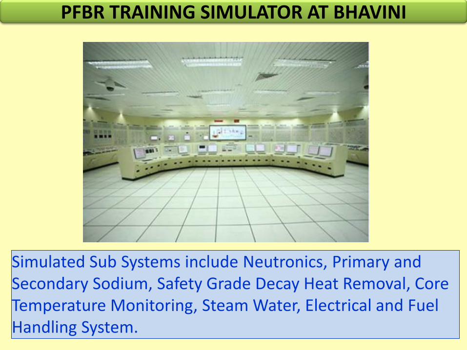
PFBR TRAINING SIMULATOR AT BHAVINI
Simulated Sub Systems include Neutronics, Primary and Secondary Sodium, Safety Grade Decay Heat Removal, Core Temperature Monitoring, Steam Water, Electrical and Fuel Handling System.

PIE of PFBR MOX Test FSA in FBTR up to 112 GWd/t
MOX fuel composition (U0.29 Pu0.71) O2
53.5% U233
O/M 1.98 to 2.00
No. of fuel pins & Fuel stack length 37 pin, 240 mm
Linear mass 2.18 g/cm
Fuel Density 91 1 % TD
Pellet diameter OD & ID 5.55 & 1.75 (mm)
Fuel pin OD & ID 6.6 & 5.7 (mm)
Clad & Wrapper material 20 % CW D9
Peak linear power 450 W/cm
Neutron dose 62 dpa
12kW 22min In (Epithermal neutrons)
• Stress-Strain curve of clad & wrapper • Diametral strain on D9 cladding has both void swelling & irradiation creep • Retention of adequate strength and ductility in D9 clad & wrapper • Fission gas release and fission product distribution by gamma scanning
X-ray & Neutron- radiographs of MOX fuel pin
Dimensional changes in wrapper & clad
Fuel stack length increase measured by different NDE techniques is in the range of 0.8 – 1.25 %
Inter pellet gap & radial cracks Central hole in the pellets
Post Irradiation Examination established that the MOX fuel and D9 clad/wrapper of PFBR test SA have performed well in FBTR up to a burnup of 112 GWd/t.

Pins being assembled
PFBR Fuel Subassembly Fabrication
Welding in progress

REACTOR
REPROCESSING
PLANT
FUEL & BLANKET PIN PLANT
FUEL
ASSEMBLY
PLANT WMP
CLOSED FUEL CYCLE
Fast Reactor Fuel Cycle
Facility (FRFCF) is being
planned to close the fuel
cycle of PFBR
Design of the facility has
been completed and MoEF
clearance has been
obtained. Consent for
construction expected.
Fast Reactor Fuel Cycle Facility

Challenges in Future FBR Development
Cost
Capital Cost
Design Improvement
Construction time
Fuel Cycle Cost Burn-up
Improved materials
Safety
Shutdown System with Passive Features
Passive Decay Heat Removal
Sodium Fire Protection
High Breeding Ratio Faster Growth Metallic Fuels

Reactor Assembly of PFBR & FBR-1
FBR 1 PFBR
Dome shaped roof slab
Support under
compression
Welded grid plate
Inner vessel with
Doubled curved torus
Thick plate
rotatable plugs
Embedded
safety vessel
Eight primary pipes
FBR 1 PFBR
Box to Dome shaped
Roof slab
Support under
Tension to compression
Four Primary
pipes to Eight
Conical to Toroidal
Inner vessel
Box to Thick plate
Rotatable plugs
Separate Safety
vessel to
Embedded vessel
Bolted to Welded
Grid plate
Motivation to introduce innovations
PFBR construction experience, significant saving in capital cost & reduced
construction time, enhanced safety…the features adoptable for future SFR series
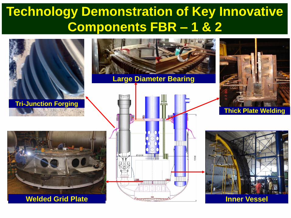
Technology Demonstration of Key Innovative
Components FBR – 1 & 2
Tri-Junction Forging
Inner Vessel Welded Grid Plate
Thick Plate Welding
Large Diameter Bearing

Metallic Fuel Development
Substantial Core Metallic Fuel in FBTR
Pin Irradiation in FBTR
Subassembly Irradiation in FBTR
120 MWe Experimental Fast Reactor
Metallic Fuel Design
1000 MWe Units
Doubling time:
30years for oxide, 12 years for metal and 8 years
for improved metallic fuel without Zr)
Reference compositions:
U-19%Pu-6%Zr (sodium bonded)
U-19% Pu (mechanically bonded / sodium
bonded)
EU-6%Zr sodium bonded fuel pins under
irradiation in FBTR
U-Pu-Zr sodium bonded pins fabricated for
irradiation in FBTR
Physicochemical property measurements and
clad compatibility studies under way

SOLID SOLIDUS SOLID + LIQUID LIQUIDUS
Unique “Spot” technique for measurement of solidus liquidus temperatures of fuel materials
Precise (+ 5 K) measurement of transition temperatures;
Provides a view of the transition and also data
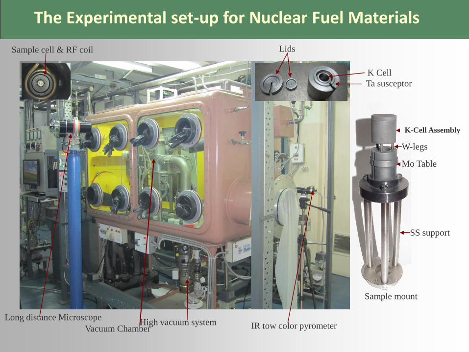
The Experimental set-up for Nuclear Fuel Materials
Long distance Microscope IR tow color pyrometer Vacuum Chamber
K Cell
Ta susceptor
High vacuum system
Lids Sample cell & RF coil
Sample mount
K-Cell Assembly
Mo Table
SS support
W-legs

0 10 20 30 40 50 60 70 80 90 100
1400
1450
1500
1550
1600
1650
1700
1750
1800
1850
1900
1950
2000
2050
2100
2150
TS Leibowitz [5]
TL Leibowitz [5]
ASM diagram [7]
TS Kanno [2]
TL Kanno [2]
TL Ohimichi [3]
TL Maeda [4]
T /
K
X Zr
TS - Present study
TL - Present study
TS Summers-Smith [1]
TL Summers-Smith [1]
Solidus-Liquidus data on U-Zr system
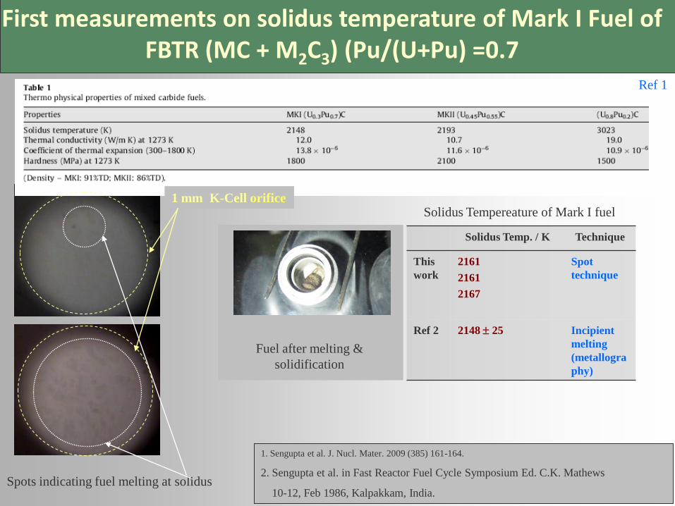
First measurements on solidus temperature of Mark I Fuel of FBTR (MC + M2C3) (Pu/(U+Pu) =0.7
Spots indicating fuel melting at solidus
Ref 1
1. Sengupta et al. J. Nucl. Mater. 2009 (385) 161-164.
2. Sengupta et al. in Fast Reactor Fuel Cycle Symposium Ed. C.K. Mathews
10-12, Feb 1986, Kalpakkam, India.
Solidus Temp. / K Technique
This
work
2161
2161
2167
Spot
technique
Ref 2
2148 25
Incipient
melting
(metallogra
phy)
1 mm K-Cell orifice
Fuel after melting &
solidification
Solidus Tempereature of Mark I fuel

Sodium Bonded Metallic Test Fuel Pin Fabrication
Sodium extruder Pin welding Sodium handling glove box with
argon recirculation system
Glove box train facility for sodium bonded
metallic fuel pin fabrication
Sodium bonded U-19Pu-6Zr test
fuel pin

Metal Fuel Test Reactor: Objectives
Full-scale testing of metal fuel subassemblies
To validate reactor physics parameters of metal fuel
Demonstrating safe operation in closed cycle mode
Mastering the industrial scale manufacture and reprocessing of metal fuel subassemblies
Material irradiation for developing advanced fuels and structural materials
Facility for isotope production for medical applications
A forerunner of a large size metallic fuelled reactors planned in future

Metal Fuel Test Reactor: Main Features
Fuel type : U-Pu-6%Zr
Bonding : Na/Mech.
Fuel smear density : 75% of TD
Clad material : Ferritic steel
Core inlet/outlet temp. : 360/510 °C
Average fuel temp. : 750 °C

Pyroprocess
activities at
IGCAR
Ceramic and Metal Waste Form Development
Studies on Direct Oxide Reduction of Actinide Oxides
Development of Materials, Coatings
Modelling and Basic Electrochemical Studies
Engineering Scale Development of Process and Equipment
Lab. scale Studies on Electrorefining and Consolidation of Cathode Deposit

Lab. scale studies on electrorefining and consolidation of cathode deposit
Lab. scale facility
Pu deposit on cathode
Pu metal
PuCl3-LiCl-KCl salt
Electrorefining of U & U bearing alloys as
anode and solid cathode studied
Electrorefining of Pu in LiCl-KCl-PuCl3
using Pu as anode (20 g) and solid cathode in
LiCl-KCl-PuCl3 electrolyte; T= 773 K
Electrorefining of Pu-Ce-La at 20 g scale
with solid cathode & Consolidation of Pu metal
deposit by melting the deposit at 1073 K
Studies on Pu alloys with other
lanthanides being continued
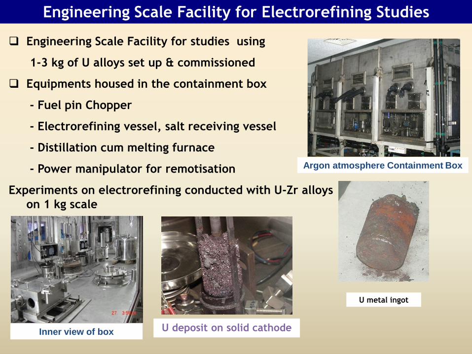
Engineering Scale Facility for Electrorefining Studies
Argon atmosphere Containment Box
Inner view of box U deposit on solid cathode
U metal ingot
Engineering Scale Facility for studies using
1-3 kg of U alloys set up & commissioned
Equipments housed in the containment box
- Fuel pin Chopper
- Electrorefining vessel, salt receiving vessel
- Distillation cum melting furnace
- Power manipulator for remotisation
Experiments on electrorefining conducted with U-Zr alloys
on 1 kg scale

30
Scaling up: Ambient Temperature ElectroRefiner (ATER)
• Ambient Temperature ElectroRefiner set up
and commissioned
• Copper electrorefining to be carried out
• Automation and remote handling aspects
to be validated and used for HTER design
ATER and sub-systems
Electrode assembly
stations
Top view of ATER

Yttria powder
Milled
particle
Cr 8.8-9.2
C 0.11-0.13
W 1.9-2.1
Ti 0.19-0.22
Y2O3 0.32-0.35
Mn < 0.04
N < 0.01
O 0.12
2.5-4.5 4.5-6.5 6.5-8.5 8.5-10.5 10.5-12.5 12.5-15
0
100
200
300
400
fre
qu
en
cy
of
the
dis
pe
rs
oid
s
Size (nm)2.5 4.5 6.5 8.5 10.5 12.5 15
9%Cr ODS Steel Fuel Cladding Tubes
Pre-alloyed
powder
Pressure Resistance Weld
6.6 mm OD/0.45mm WT/4.2 m long cladding tube

Devices developed for ISI of Main Vessel / Safety Vessel
ROBOTICS AND IN-SERVICE INSPECTION DEVICES FOR PFBR
COMPONENTS AND REPROCESSING FACILITIES
Robot system
developed for ISI of DFRP
waste vault
Power manipulator
developed for pyro
processing facility
Sample handling
robot for fuel
reprocessing plant

R&D on Safety related to Sodium
Performance Evaluation of Sodium Leak Collection Tray
SOCAFacility to simulate Na fire scenario on top shield
platform
20 ms 24 ms 32 ms 7200 ms 7600 ms 8600 ms
Sodium fire followed by cable fire
Fundamental Tests in MINA:
Sodium spray fire scenarios,
sodium fire followed by cable fire,
sodium concrete interactions,
sodium water/steam reactions,
qualification innovative sodium
sensors and sodium fire
extinguishes, etc
Medium & Large Scale
Experiments (SOCA, SFEF):
Qualification of sodium leak
collection trays, sodium fire
scenarios to investiagte the
integrity of safety related
components on the top sheild
platform
LabView Sodium School:
IGCAR-CEA Cooperation

Molten Fuel Coolant Interaction Studies
Estimation of work potential
Characterisation of debris: (constitution, size & heat trasfer)
Dispersion on core catcher
Post accident heat transfer modes
Woods metal in
water
Uranium in sodium SOFI Facility
Potential of main vessel: 1200 MJ
Grid plate melt-through scenario
Simulation of Severe Accident Scenario
• Mechanical consequence: Vessel deformations, integrity of SGDHR,
sodium release to Reactor Containment
Building
• Post Accident Heat Removal Scenario:
• Molten fuel coolant interactions
• Core catcher performance

Conclusion
• Indian fast reactor programme being developed
with comprehensive attention to all aspects
• High emphasis on safety and economics
• Fuel cycle development undertaken
simultaneous with reactor development
• Emphasis on breeding: metal fuel development
for long term
• High confidence level in manufacturing industry
• R & D in various domains, as well as human
resource development given emphasis

Thank You

Welcome
To
India


![Indian Air Force's Perspective on Remotely Piloted Aircraft [RPA]](https://img.pdfslide.net/doc/110x75/544bf9b9af7959ac438b57e2/indian-air-forces-perspective-on-remotely-piloted-aircraft-rpa.jpg)