Embed Size (px)
Citation preview

571
A PHASED ARRAY INSPECTION OF THE BORON INJECTION NOZZLES (RIB) AND PRESSURISER EXPANSION LINE NOZZLES (LEP) OF THE 900 MW PWR
Damien Desprez, Colin McNeil, Doosan Power Systems, United Kingdom
Jamal Kurdi, Johan Mognon, EDF, France
ABSTRACT This paper presents the on site development and implementation of a phased array system used for the qualified inspection of branch nozzles in the primary circuit of pressurised water power reactor plant.
Studies by EDF of areas sensitive to Thermal fatigue identified the need to inspect the Boron Injection nozzles (RIB) and Pressuriser Expansion Line nozzles (LEP) of the 900 MW PWR plant during their 30 year outage.
In conformance with the order of exploitation of November 10th 1999, EDF have had an obligation to qualify the non destructive examination of main primary circuit and secondary circuit components of PWR plant.
In 2007, Doosan Power Systems (DPS) were awarded a contract from EDF to design, develop, qualify and implement an ultrasonic inspection system to detect thermal fatigue cracks initiated on the inner surface of RIB and LEP branches nozzles of the 900MW PWR plant operated by EDF in France.
The inspection system has now been applied to components in various French power plant, including eleven in-service inspections on 4-off separate nozzle configurations : expansion nozzles (LEP), boron injection nozzles (RIB), set-on nozzle and set-in nozzles.
This presentation is the final chapter of the development and qualification process. It includes specific emphasis on the practical experience obtained from the site implementation and it’s impact on the qualification dossier.
INTRODUCTION Many papers present new concepts, laboratory studies or developments of new equipment etc. All such developments, improvements or evolutions are made with the intention of becoming industrial applications. The purpose of this presentation is to report the on-site implementation of a successful process of design, development and qualification of an innovative UT inspection for nuclear power plants.
The initial strategy for the qualification was based on input information available at the outset, but interventions on site began before the qualification of the application, therefore this body of input data has increased providing a great deal of feedback into the process. The key areas of feedback and their impact on the initial strategy are described.
A qualification process in accordance with the RSE-M standard for the non destructive examination of the main primary circuit and secondary circuit components of PWR plant is required.
The RSE-M qualification process for this inspection has been described previously; cf. 1) and 2).
INSPECTION REQUIREMENT The project covered 4 different nozzle configurations which correspond to the nozzle type and to the geometry and the position of the nozzle to primary pipe attachment weld.
The project requires detection, localisation and characterization of radial / axial defects, on the inner radius surface for LEP nozzle and on the inner radius and the bore surfaces for the RIB nozzle.
STAKEHOLDER NEEDS The main issues for EDF are :

572
Safety of the power plant
Availability of the power plant
Radiation hygiene and respect of the governing safety regulations.
Safety of the power plant
During the life of the plant, EDF must ensure the safe containment of radioactive products; to this end it is
necessary to implement a maintenance regime that requires the inspection of certain components,
specifically those related to the primary circuit.
The Boron Injection nozzles (RIB) and the Pressuriser Expansion Line nozzles (LEP) have been
identified as areas sensitive to thermal fatigue. The presence of cracking is not acceptable, and so their
detection is required.
Availability
Of course profitability is an important point; so it is desirable that time available for production is as high
as possible: the minimisation of outage duration is one of the keys to high availability.
Organisations performing maintenance activities must adopt procedures and processes that are
able to comply with the requirements of the overall outage planning in a safe and reliable way.
Radiation hygiene
Forming part of the primary circuit, the nozzles are located in areas of potentially significant radiation
exposure. As such, EDF require that all maintenance procedures address the need to minimise exposure.
This is achieved by the use of specific tools and best working practices.
The main issues for DPS overlap with those of EDF. These include the provision of advanced,
sustainable, inspection services to support the Nuclear energy sector both in the UK and Internationally.
Of course this must be delivered in a safe and reliable way to the customer’s satisfaction.
INSPECTION TECHNIQUE DESIGN
The general design of the inspection was presented in a previous publications 1) and 2). Four applications,
classified by type of nozzles "RIB or LEP" and by type of configuration "set-on" or "set-through" were
covered by the inspection specification. Each of these configurations imposes specific constraints for the
inspection design. These are defined in terms of:
• Geometric Characteristics;
• Metallurgical Characteristics;
• The extent of the zone to be examined;
• Characteristics of the defects;
• The environment differs significantly between the component configurations and sites (cf. Figures
1 to 4)

573
Figure 1 : LEP Set on Nozzle Figure 2 : LEP Set In Nozzle
Figure 3 : RIB Set on Nozzle Figure 4 : RIB Set In Nozzle
Additionally, the inspection design must allow access from the external surfaces of the components.
Further, the technique should not include beams that would need to pass through the nozzle to primary
pipe attachment weld. In other words, set-In nozzles need to be inspected from the nozzle boss and set-on
nozzles need to be inspected from the primary pipe.
EDF provided a variety of technical data at the outset of the project, this included :
• Laser study reports on the as built component geometry;
• Information relating to the manufacturing process;
• Material grain size measurements;
• Attenuation measurements from some sites;
• Site access information;
• Data related to expected exposure rates.
This information was analysed and taken into account by DPS for the design of techniques,
mockups and equipment i.e. the manipulator and the transducers.
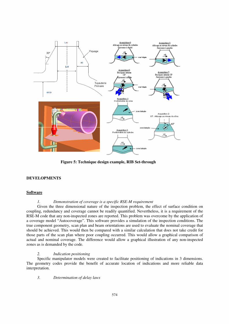
To take account of the complex geometry and the environment of the components as well as the
position in the examination zone of the possible defect, automated ultrasonic techniques were selected.
Two dimensional Phased arrays were used, these allowed the generation of beams over the spread of
orientations (angle and skew) required to obtain appropriate incidence conditions on the variety of
potential defect positions. For example, Figure 5 presents the technique design established for the RIB set-
through case.
574
Figure 5: Technique design example, RIB Set-through
DEVELOPMENTS
Software
1. Demonstration of coverage is a specific RSE-M requirement
Given the three dimensional nature of the inspection problem, the effect of surface condition on
coupling, redundancy and coverage cannot be readily quantified. Nevertheless, it is a requirement of the
RSE-M code that any non-inspected zones are reported. This problem was overcome by the application of
a coverage model “Autocoverage”. This software provides a simulation of the inspection conditions. The
true component geometry, scan plan and beam orientations are used to evaluate the nominal coverage that
should be achieved. This would then be compared with a similar calculation that does not take credit for
those parts of the scan plan where poor coupling occurred. This would allow a graphical comparison of
actual and nominal coverage. The difference would allow a graphical illustration of any non-inspected
zones as is demanded by the code.
2. Indication positioning
Specific manipulator models were created to facilitate positioning of indications in 3 dimensions.
The geometry codes provide the benefit of accurate location of indications and more reliable data
interpretation.
3. Determination of delay laws

575
An Interface with CIVA was developed to allow transfer of complex delay laws to the Ultrasonic
Flaw Detector.
Manipulator
The equipment for the inspection was designed and manufactured by Doosan Power Systems, Renfrew.
At the outset of the project there was a significant volume of input data, in particular, the general
component geometry. It was known that there could be small variations in the component geometry;
however these were not fully quantified.
It was necessary to allow some versatility in the equipment design to provide some tolerance to
variations in the component geometry. Given the high dose rates, typically 1mSv / Hr at 500mm, it was
also necessary to ensure the inspection system was tolerant to imperfect installation. Figure 6 illustrates a
typical manipulator installation.
Figure 6 : Manipulator in set-on configuration
Commissioning trials
Commissioning trials were performed; the aim of these trials was to optimise and verify the technical
performance of the candidate or selected techniques.
The trials were performed on 7 full size mock-ups with a wide range of simulated defects.
Documentation
Before the first inspection on site a dossier comprising the technical, organisational, and quality
documents were produced in accordance with EDF requirements note NT84-114.
CURRENT STATUS
The LEP set-in application was qualified in January 2012.
The RIB set-in qualification is scheduled to be qualified during 2012.
No formal qualifications are required for LEP and RIB set-on, but the qualification process has been
followed in its entirety.
INSPECTIONS
576
Of the 58 nuclear reactors operated by Electricite de France (EdF) in France, 34 are of the 900 MW type
covered by this project.
The first inspection took place at Fessenheim 1 in 2009. To date 11 units have been inspected, 6
inspections (9 nozzles) were performed in a relatively short time (actually 10 months) during 2011.
Availability of the component
The RIB LEP inspections are programmed during the 10-year outage of the units concerned. Outage
duration is a key parameter for all utilities including EDF.
The period between the shut-down of the plant and the hydraulic test of the primary circuit is
crucial as many maintenance and inspection interventions are planned during this short period.
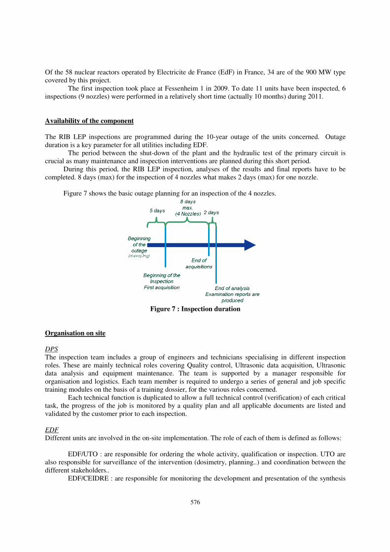
During this period, the RIB LEP inspection, analyses of the results and final reports have to be
completed. 8 days (max) for the inspection of 4 nozzles what makes 2 days (max) for one nozzle.
Figure 7 shows the basic outage planning for an inspection of the 4 nozzles.
Figure 7 : Inspection duration
Organisation on site
DPS
The inspection team includes a group of engineers and technicians specialising in different inspection
roles. These are mainly technical roles covering Quality control, Ultrasonic data acquisition, Ultrasonic
data analysis and equipment maintenance. The team is supported by a manager responsible for
organisation and logistics. Each team member is required to undergo a series of general and job specific
training modules on the basis of a training dossier, for the various roles concerned.
Each technical function is duplicated to allow a full technical control (verification) of each critical
task, the progress of the job is monitored by a quality plan and all applicable documents are listed and
validated by the customer prior to each inspection.
EDF
Different units are involved in the on-site implementation. The role of each of them is defined as follows:
EDF/UTO : are responsible for ordering the whole activity, qualification or inspection. UTO are
also responsible for surveillance of the intervention (dosimetry, planning..) and coordination between the
different stakeholders..
EDF/CEIDRE : are responsible for monitoring the development and presentation of the synthesis

577
of the qualification in the presence of the Qualification body. Ceidre are also responsible, by delegation
from EDF/UTO, for the technical supervision of the inspection as application of procedures and results
validation of the final review.
EDF/CNPE : this is the power plant team who are required to communicate the results of the
inspection with the local regulatory body before the hydraulic test of the primary circuit. The NPP are also
responsible for the supply of all logistics.
Quality assurance
A wide range of situations can be classed as “non-conformances” These can vary from parameters that are
outwith the scope of the qualification to incorrect application of the procedure. When a non-conformance
is detected, a document is written by DPS to describe the situation and the treatment. This document has
to be validated by EDF/CEIDRE (when the NDE method is concerned) and EDF/UTO. This process
ensures the traceability of the event in order to maintain the quality and control of the inspection and any
future inspections on the same component.
These documents are systematically included in the final report of the inspection and can be passed
on by the NPP to the Regulatory Body if required.
SITE IMPLEMENTATION AND FEEDBACK
The site work started before the end of the qualification process. Thus, it has been decided to conduct
inspections according to an expertise process such as defined by the RSEM code. It was therefore
necessary to designate the DPS/EDF Experts to prepare the expertise program and to deliver the expertise
report at the end of the inspection and the Expert elicitation if necessary
This allowed a great deal of valuable feed back information to be integrated into the qualification
dossier. Nevertheless, the feedback from site showed that the essential parameters that were identified
during qualification were all within the tolerances accounted for in the Technical Justification. In
particular, the calibration and qualification blocks were remarkably similar to the actual components.
Environment
As the components in question form part of a PWR Primary circuit, significant level of radiation
exposure are expected in the areas concerned. Indeed, the input data suggested that dosimetry would be an
important consideration in determination of the team size and in the design of the inspection equipment.
The difficulties caused by the environment, see Figure 8, were expected to have a direct impact on the
equipment qualification and an indirect impact on the technical qualification. During the evolution of the
project this proved to be the case.

578
Figure 8 : LEP set-on environment.
As the inspections have been undertaken on numerous occasions, it has been possible through post–
job briefing to identify and implement numerous incremental improvements in the equipment and
procedures with the objective of reducing the level of operator exposure.
Figure 9 illustrates the variation in dosimetry (per team per nozzle) that was achieved during each
intervention. The data has been normalised to take account of variations in background levels present at
each site, it is clear that a promising downward trend in exposure has been obtained (black line is a simple
best fit straight line).
These benefits are mainly due to a process of continuous improvement initiatives that were
implemented between each intervention. A variety of modifications were made, these included
improvements at all phases of the mission, e.g. mobilization, procedural and equipment modifications.
1,50
2,00
2,50
3,00
3,50
4,00
4,50
mS
v
Ident.
DOSIMETRY
Relative dosimetry / Nozzle
Linéaire (Relative dosimetry / Nozzle)
Figure 9 : Exposure Man.mSv per nozzle.
Component geometry
The design information suggests that all the components of a given type should have the same geometry,
however, from laser study information, it was expected and proved to be the case that there were certain
variations in the geometry from site to site and (in the case of RIB) between loops at the same site.
There are many parameters required to define the geometry of a nozzle, however the most

579
significant in terms of impact on the validity of these inspection are those that have an impact on the
scanning surface.
A : Set-on Nozzles : The radial position of the junction between the blend radius and the primary
pipe. This point varies as a function of the circumferential position and is also influenced by the extent of
manual grinding applied during manufacture. The inspection design required a transducer to be placed on
the primary pipe and scanned around the nozzle. The theoretical locus of this travel is governed by the
manipulator geometry, the saddle effect and certain component geometry. Nevertheless the radius of the
probe for a given circumferential location is fixed and designed to lie beyond the radius of the blend to
primary pipe junction so that the transducer remains solely on the primary pipe.
It was evident that for certain components, the as-built form of the blend radius was larger than
anticipated. This, combined with the saddle effect caused the blend radius to encroach the nominal track
of the transducer near the 90° and 270° locations. This reality had a significant impact on the validity of
the inspection design and the level of coverage that could be achieved. i.e. It would not be possible to
obtain coverage from those transducer locations at 90° and 270°. Overall coverage of the inspection
volume would not therefore be possible using the original set of focal laws.
In order to remedy the situation it was necessary to design a series of additional laws that would
provide coverage where required without relying on scan points near the 90° and 270° locations. Despite
the time pressures associated with the intervention schedule, these additional laws were determined,
verified and applied. The subsequent improvement in coverage was validated using the coverage
modelling tool, Autocoverage.
B : Set-In nozzles : The axial position of the junction between the blend radius and the nozzle boss.
Similarly, this point also varies as a function of the circumferential position and is also influenced
by the extent of manual grinding applied during manufacture. As the technique for these components is
designed for the probes to be scanned on the cylindrical nozzle boss, the variation in this parameter could
have an impact on the relative position of the scan surface and the inspection volume. Figure 10 shows
the results from a specific site where the blend radius is significantly different from the theoretical profile.
Variations associated with this feature are only problematic when the axial location is higher than the
nominal location (as is the case in Figure 10). In such a case it could be questioned whether coverage was
possible from the nozzle boss. Whilst nothing could be done to change the situation, it was nevertheless
necessary to evaluate and demonstrate the impact. In all cases it was shown that, despite the more limited
or extreme surface position, the coverage as intended by the procedure could still be achieved.
Figure 10: variation in axial position, Z, of the blend radius.
C : Set-In nozzles : The position of the upper axial position of the nozzle boss (cone cylinder
junction).
This feature is used during the installation procedure to fix the location of the manipulator. Extreme
values could have an impact on the ability to cover the complete cylindrical surface. In practice there were
significant variations in this location, since the true position of the cone /cylinder junction was always
higher than expected (+10.5 to +24.5mm). From a coverage point of view this was favourable in the sense
that the available scan surface was larger than would otherwise be the case. However there were some
580
extreme cases where the combination of this point being at a high axial location combined with a low
blend radius meant that the scan surface was significantly longer than anticipated such that there was
insufficient travel on the scanner to allow collection of the full cylindrical surface profile, i.e. at 90° and
270°. Fortunately this issue did not have an impact on the ultrasonic coverage and despite extreme
variations it was possible to cover the full extent of all the cylindrical surfaces that have been encountered
to date.
Attenuation
Attenuation due to the grain structure of the component is a very difficult parameter to control. There was
some input data available at the outset; this suggested that for some sites the grain size was of the order of
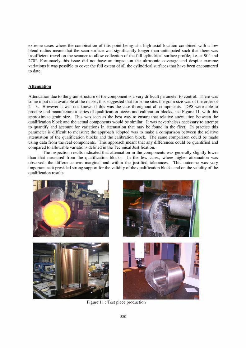
2 - 3. However it was not known if this was the case throughout all components. DPS were able to
procure and manufacture a series of qualification pieces and calibration blocks, see Figure 11, with this
approximate grain size. This was seen as the best way to ensure that relative attenuation between the
qualification block and the actual components would be similar. It was nevertheless necessary to attempt
to quantify and account for variations in attenuation that may be found in the fleet. In practice this
parameter is difficult to measure; the approach adopted was to make a comparison between the relative
attenuation of the qualification blocks and the calibration block. The same comparison could be made
using data from the real components. This approach meant that any differences could be quantified and
compared to allowable variations defined in the Technical Justification.
The inspection results indicated that attenuation in the components was generally slightly lower
than that measured from the qualification blocks. In the few cases, where higher attenuation was
observed, the difference was marginal and within the justified tolerances. This outcome was very
important as it provided strong support for the validity of the qualification blocks and on the validity of the
qualification results.
Figure 11 : Test piece production
581
Surface condition
The surface condition was known to contain some imperfections; these were in the form of scrapes, dents,
over and under-grinding. These could impact coupling to varying degrees. The strategy was to apply a 0°
beam (30° on conical surfaces) to monitor the backwall echo. This would yield any areas of poor coupling,
possibly caused by the surface condition. A profile measuring device was applied to the surface; this
would allow areas of poor coupling to be correlated with poor surface condition.
Whilst a range of beam orientations were necessary to provide coverage around the saddle shaped
geometry, this feature also helps to mitigate the impact of poor surface condition. Essentially the
inspection would benefit from a degree of redundancy, in that, a given defect could be detected from
various scan points. In the simplest sense, the application of beams in both circumferential directions
would normally allow detection from each side of any postulated defect. Further, the variety of beam
orientations applied from each side of any defect ensured there was a patch-work of transducer locations
from which any defect would be seen.. It was estimated that the presence of a localized surface
imperfection could reduce redundancy but would not impact the likelihood of detection. The coverage
actually achieved was verified during each inspection using Autocoverage.
As expected, variations in surface condition were encountered. Despite this, the inspection proved
resilient, and, by virtue of the coverage model, it was possible to quantify and demonstrate that adequate
coverage was achieved.
Artefacts
The qualification process included a number of trials on realistic test pieces. Whilst it was important to
reliably detect the defects of concern, it was also important to discriminate any artefacts that were
detected. Artefacts are non defect signals that may occur, for example, geometric echoes, effect of
subsidiary lobes etc. The source of all artefacts was analysed and this provided feed back into the
continuous evolution of the analysis procedures.
CONCLUSION
1. Design, Development and on-site implementation of an innovative UT inspection for RIB/LEP
nozzles of the 900 MWPWR is complete.
2. Nevertheless, lack of definition of the inspection requirements could lead to an inadequate
inspection and even with the best efforts it is difficult to recognise and appreciate the impact and relevance
of all inspection parameters at the outset of a development.
3. For complex inspections, if we have some doubt of the exhaustive description of the input
data, real site feed back is required in order to establish a robust qualification dossier.
4. Inspections were realized before the end of the qualification process, according to an
expertise process as required by the RSEM code.
5. LEP application is now qualified and RIB application is intended to be qualified during
2012.
6. The technique applied, the knowledge and experience acquired and the complete set of
documentation produced are now consolidated and available for application on components of similar
geometry.
REFERENCES
1) Qualification of an Ultrasonic Inspection System for the RSEM Examination of Primary Pipe Branch
Nozzle Inner surfaces Damien DESPREZ, Colin McNEIL, Doosan Power Systems, United Kingdom
Jamal KURDI, Virginie LE-GUERROUE, EDF, France Eighth International Conference on NDE in

582
Relation to Structural Integrity for Nuclear and Pressurised Components Conference, Berlin,
Germany – 9th September -1st October 2010
2) Contrôlabilité par les techniques multiéléments des piquages RIB/LEP des centrales nucléaires à eau
pressurisée Jamal KURDI, Loïc De ROUMILLY, Virginie LE-GUERROUE; EDF, France, Barry
DIKSTRA, Colin McNEIL , Damien DESPREZ, Doosan Power Systems, United Kingdom Journées
Cofrend - Dunkerque 2011 - France – 24th – 27th May 2011