Embed Size (px)
Citation preview

2 3 2 . 4 91PH
RERIC International Energy Journal: Vol. 13, No. 2, December 1991 81
A Photovoltaic Water Pump Testing Facility
P.K. Koner and J.C. JoshiPhotovoltaic Laboratory, Centre for Energy Studies
Indian Institute of Technology, DelhiNew Delhi 110016, INDIA
K.L. ChopraDirector, Indian Institute of Technology, Kharagpur
Kharagpur 721302, INDIA.LIBRARY IRC
PO Box 93190, 2509 AD THE HAGUETel.: +31 70 30 689 80Fax: +31 70 35 899 64
ABSTRACT BARCODE: yty
A closed loop and multipurpose photovoltaic water pump testing system has been designedand fabricated. It has been used to carry out a comparative study of the individual and conjugatefield performances and system efficiencies (individual components and total) of two motor-pumps.Three power sources can be used to characterize the motor-pumps and to compare the studyresults of different pump systems. A high wattage current/voltage characteristics meter for solarcells or arrays and a switching device for changing the combinations ofPV modules have been de-signed and developed and these were connected to the testing system. The importance and the fieldperformance of this test system have been discussed by a comparative and individual technicaland cost analysis study of two different motor-pump systems. A comparative study of both thesystems show the superiority of the DC series motor-pump (C.E.L., India) system under Indianconditions.
INTRODUCTION
Photovoltaic (PV) water pumping as an application of PV energy is expected to increase inpopularity in the near future. The characteristics of a PV pumping system depend on a number ofrequirements and environmental parameters. Therefore, before the installation of a PV waterpumping system on site, a detailed study of its performance equivalent to outdoor conditions
* should be made. The manufacturer's specifications are not sufficient to design a system for out-door conditions because the specified data are generally quoted only for the best results of the
, system under a particular set of conditions, viz., water head and voltage. The main variables underoutdoor conditions are the variation of seasonal ground water depth and change in solar insolation
: level during a day. For studying the performance of a PV water pump system, a test facility isi required. Different types of PV water pump testing systems have been reported in the literature [1-l 3], However, these test systems were designed and developed for the study of a particular type of
PV water pump system. A modified and versatile closed loop and multipurpose PV water pumptesting system has been designed and fabricated and is discussed herein.
The field performance of the testing system has been verified by a comparative study of twodifferent water pump systems. Individual component and total system studies, operating norms

82 RERIC International Energy Journal: Vol. 13, No. 2, December 1991
and cost analysis for both the systems have been made with solar insolation and static water headas variables. The average daily efficiency and projected specific capital cost (S.C.C.) have beencalculated from the collected field data and compared for both the systems.
DESCRIPTION OF TESTING FACILITY
The design versatility of PV water pump systems, as shown in Fig.l, necessitates the designand development of a multipurpose PV water pump testing system, and this is shown in Fig. 2.The testing system consists of a 2 kWp PV generator, a 12 kVA battery bank, a 1 kVA DC-ACinverter to produce AC power from a PV generator, a 1 kVA DC-AC power supply to supplyconstant voltage to the load, a 220 volts AC supply,.a 500 watts current/voltage characteristicsmeter for solar cells and arrays, a 600 watts MPPT and a switching device for changing thecombination of PV modules. This system can study the individual and comparative field perform-ances of a number of different water pump systems. Different power sources e.g. battery, DCconstant voltage source, PV generator, AC supply are connected to the water pump testing systemto compare their performances. The system has three pumps in parallel, separated by valves andflanges, in such a fashion that their individual and conjugate performance can be studied. A globevalve regulating device has been employed in the PV water pump set-up to create back pressure onthe pump for the calibration of an equivalent water head. The developed back pressure has been
Solar generatorPower
condensorMotor Pump
PVGenerator
Non-trocking
Batteryor
SMPS
-InverterDC-AC
A.C.motor
Synchronous]-
\ Asynchronous (•
Converter DC- DCor MPPT
Switchingcontroller
Batterycharger
Batterybank
Directcoupling
DCmotor
Separatelyexcited
— Series I - - Centrifugal
Shunt
\ Volumetric
M P P T - M a x i m u m power point trackerSMPS-Swi tch mode power supply
Fig. 1. Block diagram for the components of a photovoltaic water pump system.

RERIC International Energy Journal: Vol. 13, No. 2, December 1991 83
PVGenerator
- I-VPlotter
Pressuregauge
Globevalve
Fig. 2. Experimental set-up of photovoltaic water pump.
Table 1. Specification of C.E.L. cz-Si PV module at STC.
No. of Solar Cells(connected in series)
36
Area of EachSolar Cell
(cm)
78.5
ym
(volts)
21.0
(amps)
2.2
(volts)
16.2
L(amps)
1.98
(watts)
32.0
measured and calibrated by a pressure gauge where 1 kg/cm2 is equal to a water head of 10 metres.One water meter is used here for measuring the flow rate and total volume of water for a day. Toevaluate the motor constant (M) and torque of the system, speed is an important parameter. Thespeed of the system has been measured by using a tachometer.
PV Generator
The PV generator is formed by 70 PV modules which are manufactured by C.E.L., India.The specifications of these modules are shown in Table 1.
The PV generator can be characterized under field conditions by drawing current-voltagecurves by a high wattage I-V plotter. Therefore, a high wattage current/voltage characteristicsmeter is an important component of a PV water pump testing facility. From the I-V curves, V ,Im, Ix and Vx of the PV generator are found. The efficiency (Ea) of the PV array can be computedby measuring solar insolation as
E = P x 100/(S/x/t) (1)

84 RERIC International Energy Journal: Vol. 13, No. 2, December 1991
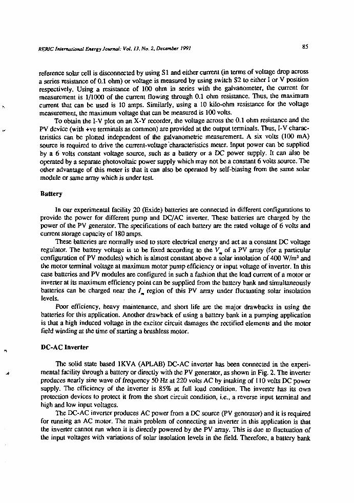
To study the performance of the PV generator, a 500 watts current/voltage characteristicsmeter has been designed and fabricated as shown in Fig. 3. The basic principle of the electronicload current/voltage characteristics meter is described. The resistance of a power transistor isvaried from almost zero to infinity by controlling its base current from 0 to ( / ^ by changing itsvoltage from 0.7 volt to 0.0 volt Therefore, the operating point of the PV device is varied fromnear short circuit to open circuit. Since the collector to emitter saturation voltage of the transistoris 0.7 volt in ON condition, the voltage across the PV device does not reach 0.0 volt correspondingto short circuit. However, this does not affect the llc value because the current is nearly constantuntil the voltage is a few volts.
In this plotter, a galvanometer is used for measuring three parameters, namely: solar insola-tion, current, and voltage of the solar cells or array by proper switchings. On connecting a refer-ence solar cell (0.036 cm1) using SI directly to the galvanometer (resistance nearly 0.0 ohm), wecan obtain the solar insolation in terms of the short circuit current measured. Since maximumgalvanometer current limit is 12 mA, this will give us a maximum of 1200 W/m2 solar insolation,because the short circuit current of the reference solar cell is 12 mA at a solar insolation of 1200W/m2. For I-V measurement of a PV device, the galvanometer is used as a voltmeter. The
0.1 Si.
2N3773-
100 J l-VWVV-
O S 2
10KJL
Fig. 3 . Circuit of current/voltage plotter for solar cells and array.
RER1C International Energy Journal: Vol. 13, No. 2, December 1991 85
reference solar cell is disconnected by using SI and either current (in terms of voltage drop acrossa series resistance of 0.1 ohm) or voltage is measured by using switch S2 to either I or V positionrespectively. Using a resistance of 100 ohm in series with the galvanometer, the current formeasurement is 1/1000 of the current flowing through 0.1 ohm resistance. Thus, the maximumcurrent that can be used is 10 amps. Similarly, using a 10 kilo-ohm resistance for the voltagemeasurement, the maximum voltage that can be measured is 100 volts.
To obtain the I-V plot on an X-Y recorder, the voltage across the 0.1 ohm resistance and thePV device (with +ve terminals as common) are provided at the output terminals. Thus, I-V charac-teristics can be plotted independent of the galvanometric measurement. A six volts (100 mA)source is required to drive the current-voltage characteristics meter. Input power can be suppliedby a 6 volts constant voltage source, such as a battery or a DC power supply. It can also beoperated by a separate photovoltaic power supply which may not be a constant 6 volts source. Theother advantage of this meter is that it can also be operated by self-biasing from the same solarmodule or same array which is under test.
Battery
In our experimental facility 20 (Exide) batteries are connected in different configurations toprovide the power for different pump and DC/AC inverter. These batteries are charged by thepower of the PV generator. The specifications of each battery are the rated voltage of 6 volts andcurrent storage capacity of 180 amps.
These batteries are normally used to store electrical energy and act as a constant DC voltageregulator. The battery voltage is to be fixed according to the Vm of a PV array (for a particularconfiguration of PV modules) which is almost constant above a solar insolation of 400 W/m2 andthe motor terminal voltage at maximum motor pump efficiency or input voltage of inverter. In thiscase batteries and PV modules are configured in such a fashion that the load current of a motor orinverter at its maximum efficiency point can be supplied from the battery bank and simultaneouslybatteries can be charged near the Im region of this PV array under fluctuating solar insolationlevels.
Poor efficiency, heavy maintenance, and short life are the major drawbacks in using thebatteries for this application. Another drawback of using a battery bank in a pumping applicationis that a high induced voltage in the excitor circuit damages the rectified elements and the motorfield winding at the time of starting a brushless motor.
DC-AC Inverter
The solid state based 1KVA (APLAB) DC-AC inverter has been connected in the experi-mental facility through a battery or directly with the PV generator, as shown in Fig. 2. The inverterproduces nearly sine wave of frequency 50 Hz at 220 volts AC by intaking of 110 volts DC powersupply. The efficiency of the inverter is 85% at full load condition. The inverter has its ownprotection devices to protect it from the short circuit condition, i.e., a reverse input terminal andhigh and low input voltages.
The DC-AC inverter produces AC power from a DC source (PV generator) and it is requiredfor running an AC motor. The main problem of connecting an inverter in this application is thatthe inverter cannot run when it is directly powered by the PV array. This is due to fluctuation ofthe input voltages with variations of solar insolation levels in the field. Therefore, a battery bank

g6 RERIC International Energy Journal: Vol. 13, No. 2, December 1991
or electronic control device is required which decreases the total system efficiency. Anotherproblem is that the inverter is tripped by passing a high current at the time of starting the motor.
MPPT (DC-DC Converter)
One 600 watts MPPT (60V and 10A) is connected to our testing facility, which is designedand developed by CNRS (France). It is operated by a 220 volts AC supply.
The matching of the load to the solar cell array is accomplished by incorporating an elec-tronic control device - an MPPT for maximum utilization of PV energy into the system. TheMPPT may be viewed as a time variable transformer (TVT), in which the transformation ratio ischanged electronically, corresponding to the variations of the load operating point due to thevariations of the insolations. The basic principle of an MPPT is that it forces the pump to trackelectronically the maximum power of a PV array at the given load. It is reported [4] that a singlestage centrifugal pump, for an application of a static water head of less than 10 metres, connectedwith a DC motor, can be designed in such a way that it can track near the maximum power pointof the PV array output from morning to evening without an MPPT. However, a multistage cen-trifugal pump or a positive displacement pump, for a static water head of more than 10 metres,connected to a DC motor cannot track the maximum power of a PV array for a whole day withoutan MPPT.
Switching Device
The electrical coupling efficiency of a photovoltaic water pump system increases [5,6] byusing an appropriate combination of PV modules in accordance with the variation of solar insola-tion levels. If the number of modules connected in parallel is increased at a low solar insolationlevel by reducing the number of modules connected in series (where the total number of modulesis fixed), the field performance efficiency of the direct coupled pump is improved. An automaticcontrol electronic circuit, as shown in Fig. 4, for changing the combinations of PV modules hasbeen designed and fabricated and consists of:
i) a sensing circuit,ii) a comparator circuit, andiii) a switching circuit.The sensing circuit senses solar insolation by the LDR or short circuit current of a PV device.
The resistance of the LDR varies with solar insolation levels. This LDR is connected in series withanother resistance (10 k) across a 12 volts DC source. The voltage of the junction point (A)between the resistance and the LDR varies with solar insolation levels in the field and it sensed in
-terms of voltage to pin No.2 of two ICs (311).-This sensing signal is compared with a reference"signal which is equivalent to the 'cut-off solar insolation' of a particular pump in a comparatorcircuit, as discussed by Koner et al. [7]. Two potentiometers (20 k) are used across the same 12volts DC supply for producing fixed reference voltage for the two ICs. These reference voltagesare supplied to pin No.3 of these ICs. A voltage equal to that developed at point A for a particularsolar insolation can be generated for the ICs' reference voltage by controlling the potentiometer.By this process, the reference voltage can be changed for different pumping systems according totheir 'cut-off solar insolations'.

RERIC International Energy Journal: Vol. 13, No. 2, December 1991 87
ce.o i
o
8" 1 2
100
^L100Mq>L
SL-100
la)
••-in
•-ii
So-,
7o—
1XJ
1_LT
6o-
5o-
(b)
3 2 10 0 0
5 6 «0 Q 0
111 o-o l
+ 12V(C)
-ve
TJ
. 80 0
TL,Fig. 4. Automatic switching controller circuits for changing the pattern of
combining the P V modulesa) Sensing and comparator circuitb) Connecting patterns of the terminals of PV modules.c) Relay circuit

88 RER1C International Energy Journal: Vol. 13, No. 2, December 1991
Three combination patterns of PV modules can be obtained by this facility. At very low solarinsolation, two ICs and three relays are at 'OFF condition. At that time, for a particular arrange-ment of the terminals of the PV modules, it would give a particular configuration. IC-1 will be'ON1 and IC-2 will be 'OFF at medium solar insolation. Because of the 'ON' condition of IC-1, thefirst two relays will operate and change the configuration for a second set. When the solar insola-tion is high, both the ICs will turn 'ON'. The relay drive circuit is configured in such a fashion thatwhen both ICs are at 'ON' condition, only relays 1 and 3 will operate and it will give the third typeof combination of PV modules.
Each relay draws a current of 250 mA which cannot pass through any IC. Therefore, a buffercircuit has been connected in between the ICs and the relays, which comprises two SL-100transistors. The solar insolation varies very rapidly in the field which generates a highly fluctuat-ing voltage at point A. To stabilize this fluctuation, one 1000 mfd capacitor is connected betweenpoint A and the ground.
Motor
In this experimental facility, two types of AC and DC motors can be characterized bymeasuring their terminal voltage, intake current, total resistance of field and coil and speed of themotor. A DC motor directly connected to a PV generator is cheaper and it simplifies the systemdesign as compared to the use of an AC motor for a stand alone PV system. DC motors can beclassified into three categories according to their mechanism as: i) scries, ii) shunt and iii) sepa-rately excited. Among these motors the DC series motor has been chosen as a specific example inthis study. A DC series motor can be characterized as
V, = ' „ * , + Em (2)
Ea = MIaM> (3)
T = M (/,)* (4)
Em = P^/P^ = M^VIiyj) (5)
Pump
Pumps are also divided into two categories according to their working mechanism: i) Roto--dynamics and ii) Displacement. Both type of pumps can be characterized in the present facility bythe measurement of the speed, water head and flow of a pump. The rotodynamics pump is a venti-lator load torque pump which can be matched to a PV generator without power conditioning for astatic water head of less than 10 metres. The centrifugal pump was chosen for verifying the per-formance of the test system. A centrifugal pump can be mathematically characterized as
h = Kpl (Wf (6)
Q = Kp2*r (7)
, = gQhl{WV) (8)

RERIC International Energy Journal: Vol. 13, No. 2, December 1991 89
OTHER OPTIONS OF THE TESTING FACILITY
Apart from the technical studies of the PV water pump system, the testing facility has theoption of measuring the operating norms, average daily efficiency and the cost analysis of thesystem as discussed below.
Operating Norms
The operating norms to design a PV water pump are: i) current, ii) voltage of the motor-pump at its maximum efficiency point and its threshold condition, and iii) threshold solar insola-tion for a particular load. The required threshold solar insolation not only depends on the startingvoltage and current, it also depends on the series and parallel combination of PV modules. Thethreshold solar insolation can be reduced by changing the combination of the PV modules.
Average Daily Efficiency
The average daily efficiency (E *) of PV water pump system is defined asmp •
total water discharged in one day (watts) x 100
V = (9)solar insolation in one day x area of the PV array (watts)
The average daily efficiency can be maximized by either increasing the individual compo-nent efficiency or by reducing the operating norms of the PV water pump or both.
Projected Specific Capital Cost
Projected specific capital cost (SCC) is not an economic analysis of a system. It can give apreliminary idea about the cost of a system only. It is defined [4] as
SCC = Clip g h VJ Rs./KJD (10)
FIELD PERFORMANCE OF THE TESTING FACILITY
To verify its field performance we have measured an array comprising of 5 series and 4parallel C.E.L. PV modules. Figure 5 shows the I-V plot of a C.E.L. (Central Electronics Ltd., Sa-hibabad, India) PV module using an X-Y plotter and galvanometer. The two curves are nearlyidentical. The slight difference in current values is due to the resistance value not being exactlyequal to the calibrated value. This difference can be eliminated by using precision resistances. Thephotovoltaic parameters using plotter are comparable to the values measured using a maximumpower point tracker (which is available in our laboratory). Table 2 shows a comparison of thevalues.
This meter has the advantage that it can operate by self-biasing. Therefore, an I-V plot of aC.E.L. PV module has been made by using a constant 6 volts input and direct input power supplyfrom a PV module which is under test, as shown in Fig. 6. The I-V curve of one PV module is

90 RERIC International Energy Journal: Vol. 13, No. 2, December 1991
Galvanometer o- o
Voltage
Fig. 5. Measurement of 1-V performance ot a r v module by galvanometer and X-Y recorder.
6V Constant sourceSelf biasing
Voltage
Fig. 6. Comparison of I-V performance for self-biasing and constant 6 volts source.

RERIC International Energy Journal: Vol. 13, No. 2, December 1991 91
found to be shifted from that which is obtained when the plotter is supplied from an independent 6volts source. This little shift is, however, negligible( less than 1% of Iic). Therefore, measurementunder self-biasing can be done avoiding use of any other source without affecting the currentvalues.
The performance of the automatic control switching has been checked by the experimentalstudy of a pump (C.E.L.) in the field. The improved daily average efficiency of the pump using theswitching device and the accuracy of the solar insolation level for switching are shown in Fig. 7.
Table 2. Comparative performance between present plotter and MPPTat solar insolation 970 W/m2 and ambient temperature 32°C.
Configuration
of PV Modules
l sx lp2sx2p5sx4p
Present Plotter
18.035.872.0
L1.93.98.0
Pm
17.971.8391
Voc
18.036.0
MPPT
/ Psc m
2.0 18.24.0 72.5
not possible
100
"^ 7 5
uc
g> 50
I 58 30
20
10
o — -o E- (a)
(b)
(a). —-o
(c)
(c)
.— — - o
"200 ^.00 600 800 1000
Solar insulat ion ( w / m )
Fig. 7. Variations of different coupling efficiencies of C.E.L. photovoltaic water pump systemwith solar insolations under different combinations of PV modules:a) 4 series x 6 parallel; b) 6 series x 4 parallel; and c) 8 series x 3 parallel.

92 RERIC International Energy Journal: Vol. 13, No. 2, December 1991
FIELD PERFORMANCE OF PUMP
The testing facility has been used to conduct a comparative field study of two differentsystems, using a series DC motor-pump (C.E.L., India) and a brushless DC motor-pump (K.S.B.,AQUSAL 50M, Germany), the specifications of which are given in Table 3.
The C.E.L. pump is characterized by a standard DC power supply as shown in Fig. 8. TheK.S.B. pump is characterized by using different combinations of PV modules at different times ofday as shown in Fig. 9. The reason for doing so is that the K.S.B. pump system has a brushless DCmotor which cannot be directly connected to a battery bank or a constant voltage source. Fromthese studies and the field condition Vm and Im data of the PV array as measured by an I-V plotter,the requirement of the optimum number of PV modules connected in series and in parallel hasbeen found. It is observed that (i) three strings of PV modules (C.E.L.) in parallel, each comprisingseven PV modules in series and (ii) four parallel strings each with five PV-modules in series arerequired to get the optimum efficiency for the C.E.L. and K.S.B. pumps, respectively.
The power intake of a motor pump in terms of operating voltage and current, maximumpower of a PV generator, flow rate, speed, threshold conditions of a PV water pump and waterdischarge for a standard day of both systems, have been collected from field study, where waterhead and solar insolation are variables. The motor-pump efficiency and coupling efficiency havebeen calculated and the variation of those for both the systems with solar insolation are shown inFigs. 7-9. The motor-pump efficiency, daily average efficiency and SCC have also been calculatedfrom these data for different water heads. A comparative study of both systems is shown in Table4. They could not be compared at the same water head because the C.E.L. pump efficiency ismaximum at 10 metres whereas the K.S.B. pump efficiency is maximum at 6 metres static waterhead. The reported [4] projected SCC of K.S.B. pump is $1.5 /KJD at a static water head of 6metres which is comparable with that of the present study.
2060 70 " 80 90 100
D C Voltage (vo l ts )
Fig. 8. The motor-pump efficiency of C.E.L. pump system versus motor terminal voltage forthe water head of: a) 5 metres; b) 7 metres; and c) 10 metres.

RER1C International Energy Journal: Vol. 13, No. 2, December 1991 93
60
£ 5 0
3a.
| * o
30
20
o Motor pump efficiency
• Total efficiency ^ — * \
o x
1 1
3.0
- 2 . 0
oCa>
O
"o
400 500 600 700 800 9001.0
100
>•
1 90
eff
ing
I 80
70
/ St~ / / /
' / /isT ° ""Ov,,0,
o Array efficiency
• Coupling efficiency
I l I400 500 600 700 800 900
Solar insulation ( w / m )
5.0 £u
a
A.S <
4.0
Fig. 9. Array efficiency and different efficiencies of K.S.B. pump versus solar insolationfor the combination of PV-modules:a) 5 series x 3 parallel; b) 5 series x 4 parallel; and c) 4 series x 4 parallel.

94 RERIC International Energy Journal: Vol. 13, No. 2, December 1991
Table 3. Specifications of water pump systems.
Description of Pump Rated voltage(volts)
Rated wattage(watts)
Water head up to(m)
CJE.L. DC series motor 60and centrifugal pump
K.S.B. brushless DC motor 68and centrifugal pump
300
480 11.5
Table 4. Comparison of the field performances of C.E.L. and K.S.B.photovoltaic water pump systems.
Characteristics
\ i~-» J L / V < I A
Total water dischargefor a standard day(6 kWh/day)
Capital cost
Threshold condition:VoltageCurrentSolar insolation
Average daily efficiency
Projected SCC (RS./KJD)
C.E.L. water pump
40%atWH=10m39%atWH= 7 m37%atWH= 5 m
26matWH=10m38matWH= 7m
Rs. 52000.00
at WH = 7 m63 volts2.3 amps400 W/m2
1.34%atWH=10m1.35%atWH = 7m
20.4 at WH= 10m20.0atWH= 7m
K.S.B. water pump
47%atWH = 8m58%atWH = 6m52% at WH = 5 m
48matWH = 7m58matWH = 5m
Rs. 67000.00
atWH = 6m45 volts3.1 amps380 W/m2
1.90%atWH = 6m1.68%atWH = 5m
20.3atWH = 6m23.1atWH = 5m

RERIC International Energy Journal: Vol. 13, No. 2, December 1991 95
CALCULATION PROCEDURE
The different efficiencies of a PV-water pump system are the PV array efficiency (£o),motor-pump efficiency (£_), power conditioner efficiency ( £ ) , electrical coupling efficiency(£/), hydraulic coupling efficiency (£/) and the total system efficiency (E). The array efficiencyhas already been defined in equation (1). The motor and pump efficiencies can be separatelyevaluated using equations (5) and (8) by an indirect process for mono-block motor-pump systems.However, the motor-pump efficiency has been directly evaluated by the following equation
^ ,a) ( i i )
Other efficiencies can be computed by the following equations
*: = V.I.WJJ <13>
Eck = gQhl(y,Ia) (14)
£, = £ * ( £ * < * £ / ) * £ , , (15)
OBSERVATIONS AND DISCUSSIONS
As shown in Fig. 9a, the array efficiency varies with solar insolation levels, which is ex-plained by the variation of series resistance effect of the solar cell. The series resistance of a solarcell decreases with the increase of solar insolation because of the decreased sheet resistance of PVmaterial. Therefore, the increase of array efficiency with increased solar insolation has thus beenfound in the first portion of the Fig. 9a for any combinations of PV modules. Another factor whichaffects the array efficiency is the temperature. At higher solar insolation levels, the array effi-ciency is reduced because the temperature effect is dominant as compared to the sheet resistanceeffect of the solar cell in this portion. Another source of variation of array efficiency whichdepends on the combination of PV modules is due to the effect of self-shadowing from the frontcontact grid of a single crystalline solar cell module [8].
Wide deviations of field measured values of Vm and Im of the PV array from quoted valueshave been found. The cause of the variations is due to the involvement of a large number of envi-ronmental factors as discussed and modelled in Ref. [9].
The reported highest water heads of C.E.L. and K.S.B. pumps are 6 and 11.5 metres respec-tively. The K.S.B. pump cannot raise the water head more than 10 metres whereas the C.E.L.pump can easily raise the water head up to 10 metres with higher efficiency. The efficiency of theCEIL, pump increases with increasing water head, but the K.S.B. pump efficiency increases tosome extent with fixed value of water head but then it decreases with increasing water head asshown in Table 4. A discussion of these effects due to the design of the pump is reported in Ref.[10].
An electronic controller for changing the configuration of PV modules has been tested in thefield to improve the daily average efficiency of the C.E.L. pump. Using this instrument thevariations of coupling efficiencies of the CJE.L. pump with different combinations of PV modules,

96 RERIC International Energy Journal: Vol. 13, No. 2, December 1991
at various solar insolation levels, are shown in Fig. 7. At least three combinations are required toget an optimum match between the pump and the PV generator for the solar insolation levels from200 W/m2 to 1000 W/m2 [5,6]. However, in this study, it was found that two combinations are suf-ficient to get the optimum hydraulic efficiency as shown in Fig. 7. The third combination is notrequired because in this combination electrical coupling efficiency is improved whereas the hy-draulic efficiency reduces drastically due to the under voltage of the motor.
CONCLUSIONS
A multipurpose photovoltaic water pump testing system has been successfully designed andfabricated. The testing system has been used to undertake a comparative study of two differentpump sets in the field. From this comparison study it can be observed that the C.E.L. PV waterpump is a better choice than the K.S.B. pump system under Indian conditions for the followingreasons:
i) the C.E.L. pump is available "off the shelf in the Indian market;ii) even though the efficiency of the C.E.L. subsystem is lower, the SCC is comparable to
thatoftheK.S.B.;andiii) the C.E.L. subsystem efficiency is affected less by a change of water head and solar
insolation compared to the K.S.B. subsystem.
NOMENCLATURE
SI = Solar insolation, W/m2
STC = Standard test conditionA = Area of PV array, m2
MPPT= Maximum power point trackerVm = Voltage at maximum power point of a PV array, voltsIm = Current at maximum power point of a PV array, ampsIK = Short circuit current of a PV array, ampsV^ = Open circuit voltage of the PV array, voltsIB = Base current of transistor, ampsla = Armature current of the motor, ampsVt = Motor terminal voltage, voltsRt = Total resistance of armatureand field coil, ohmvv"" = Speed of the motor, rad/sY? = Speed of the pump, rad/sT* = Torque of the motor, Nm7* = Torque of the pump, NmM = Motor constant, Nm/A2
Em = Motor efficiency, %Ep = Pump efficiency, %Q = Flow rate, 1/sC = Capital cost of a PV-water pump system, Rs.p = Density of water, kg/cm2

RERIC International Energy Journal: Vol. 13, No. 2, December 1991 97
g = Gravitational acceleration m/s2
h = Static water head, mVw = Total volume of water pumped per standard day, m3
Kpt and K 2 are the pump constants,
REFERENCES
1. Hermann, B., H. Karl, E. Kopf and G. Lehner (1986), Realistic Indoor Testing of Pho-tovoltaic Water Pumping System, Solar Energy, Vol.38, No.4, pp.275-279.
2. Pulfery, D.L., P.R.B. Ward and W.G. Dunford (1987), A Photovoltaic Powered System forMedium Head Pumping, Solar Energy, Vol.38, No.4, pp.255-256.
3. Chandratilleke, T.T. and J.C. Ho (1986), A Study of a Photovoltaic Array for Water Pump-ing, Solar & Wind Technology, Vol.3, No.3, pp.59-71.
4. Report of the UNDP Project GLO/80/003 (1983), Sir William Halcrow and Partners in asso-ciation with Intermediate Technology Power Ltd.
5. Faldella, E. (1989), Matching and Control Technique for Optimizing Automatic Managementof Photovoltaic Pumping Systems, presented at the Workshop on Materials Science andPhysics of Non-conventional Energy Sources, Trieste, Italy.
6. Salameh, Z. and C. Liang (1990), Optimum Switching Points for Array ReconfigurationController, Proc. of 21st IEEE Photovoltaic Specialists Conf, pp.97l-976.
7. Koner., P.K., J.C. Joshi and K.L. Chopra (1991), Study of a Pumping load by DifferentConfigurations of Photovoltaic Modules, paper presented at ISES Solar World Congress-1991, Denver, Colorado, U.S.A.
8. Koner, P.K., V. Dutta and K.L. Chopra (1992), Grid Shadowing Effect on Field Performanceofcz-Si Solar Cells and Array, Accepted for Presentation at ASME International Solar En-ergy Conference, to be held at Hyatt Regency, Maui, Hawaii, April 4-8,1992.
9. Koner, P.K., J.C. Joshi and K.L. Chopra (1991), Quantitative Field Performance Analysis ofPhotovoltaic Array, International Journal of Energy Research, Vol. 15, No.6, pp.473-482.
10. Koner., P.K., J.C. Joshi, A.K. Mukerjee and K.L. Chopra (1991), Analysis of OptimumMatching of a D.C. Series Motor Driven Centrifugal pump to a Photovoltaic generator,International Journal of Renewable Energy, in press.