Embed Size (px)
Citation preview
A Physicist’s Guide to the International Electrotechnical Commission
Geoffrey S. Ibbott, Ph.D.Chair, Subcommittee 62CMember, WG-1Chair, US TAG to WG-1
1Thursday, August 3, 2006
2Thursday, August 3, 2006

Role of the IEC and Impact of its Standards
• IEC's international standards facilitate world trade by removing technical barriers to trade, leading to new markets and economic growth.
• They also represent the core of the World Trade Organization's Agreement on Technical Barriers to Trade (TBT), whose 100-plus central government members explicitly recognize that international standards play a critical role in improving industrial efficiency and developing world trade.
• Using IEC standards for certification at the national level ensures that a certified product has been manufactured and type-tested to well established international standards. The end user can be sure that the product meets minimum (usually high) quality standards, and need not be concerned with further testing or evaluation of the product.
3Thursday, August 3, 2006

The International Electrotechnical Commission
68 member nations (including associate membersProduces standards addressing the design of electrotechnical equipment.
Safety and performance standards apply to manufacturer’s design and construction
Compliance tests can be type tests, or site tests
Site tests sometimes incorporated into acceptance testing procedures
4Thursday, August 3, 2006

Adoption of IEC Standards
In Europe:
IEC standards selected for “parallel voting” by CENELECWhen approved, assigned “EN” numberStandards adopted as written and carry the force of lawHowever, up to EC members to enforce
5Thursday, August 3, 2006

Adoption of IEC Standards
In US:
IEC standards (or sections) incorporated into ANSI standards, FDA regulations, NEMA guidelines, etc.IEC standards can be used as written; FDA requires vendor to report compliance
Elsewhere?
6Thursday, August 3, 2006
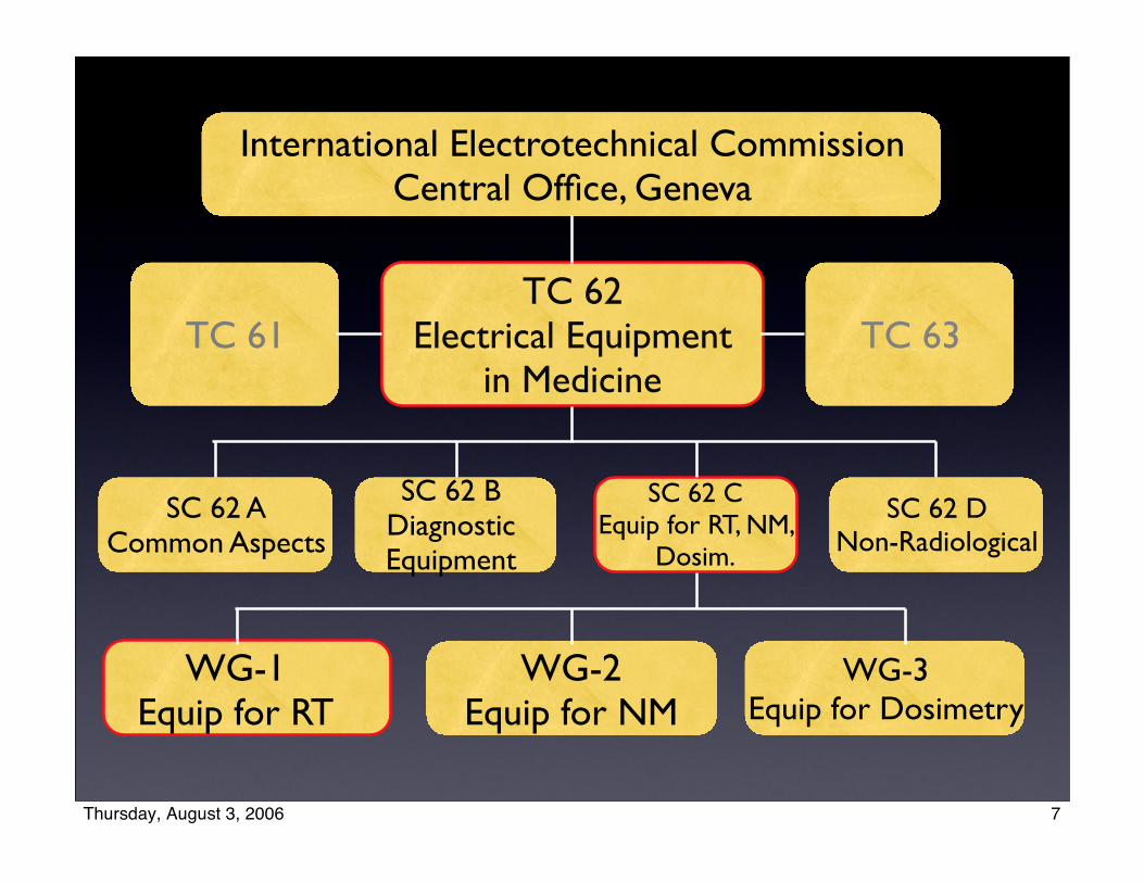
SC 62 CEquip for RT, NM,
Dosim.
International Electrotechnical CommissionCentral Office, Geneva
TC 62Electrical Equipment
in MedicineTC 61 TC 63
SC 62 ACommon Aspects
SC 62 BDiagnosticEquipment
SC 62 DNon-Radiological
WG-1Equip for RT
WG-2Equip for NM
WG-3Equip for Dosimetry
7Thursday, August 3, 2006
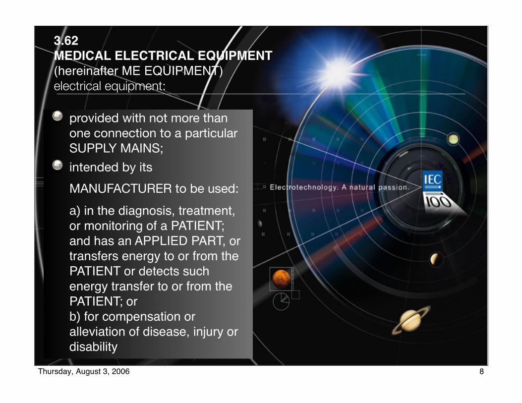
3.62MEDICAL ELECTRICAL EQUIPMENT (hereinafter ME EQUIPMENT)electrical equipment:
provided with not more than one connection to a particular SUPPLY MAINS;
intended by its
MANUFACTURER to be used:
a) in the diagnosis, treatment, or monitoring of a PATIENT; and has an APPLIED PART, or transfers energy to or from the PATIENT or detects such energy transfer to or from the PATIENT; orb) for compensation or alleviation of disease, injury or disability
8Thursday, August 3, 2006

Role of Working Group
Develop Standards
Safety Standardssafety and “essential performance”
Technical ReportsPerformance StandardsPerformance Guidelines
9Thursday, August 3, 2006

IEC 60601-seriesCollateral standards
More general requirements:
60601-1-1 Medical electrical systems 60601-1-2 Electromagnetic
compatibility 60601-1-3 X-ray - radiation protection 60601-1-4 Programmable medical
electrical systems 60601-1-5 X-ray - image quality/dose 60601-1-6 Usability 60601-1-7 Not used 60601-1-8 Alarm systems
606-1-1-3
606-1-1-2
606-1-1-1
60601-1
GeneralStandard
10Thursday, August 3, 2006
Electromagnetic Compatibility
•For medical equipment, see 60601-1-2 (9/2001)•To be included in 60601-1 3rd edition
11Thursday, August 3, 2006

60601-2-5Particular require
Ultrasound therapy equip.
60601-2-4Particular require
Defibrillator/ monitors
60601-2-3Particular require
Short-wave therapy equip.
60601-2-2Particular require
HF surgical equipment
60601-2-1Particular
requirements
Medical accelerators
Particular standards
50+ standardsAmend the general
requirements for particular types of equipment
60601-1-3
General requirements60601-1-2
General requirements60601-1-1
General requirements
60601-1
General requirements
General standardsApply to all medical electrical equipment
12Thursday, August 3, 2006

62C Safety Standards
13Thursday, August 3, 2006

62C Safety Standards
60601-1General Standard
60601-1-XCollateral Standards
13Thursday, August 3, 2006

62C Safety Standards
60601-1General Standard
60601-1-XCollateral Standards
60601-2-XParticular Standards
13Thursday, August 3, 2006
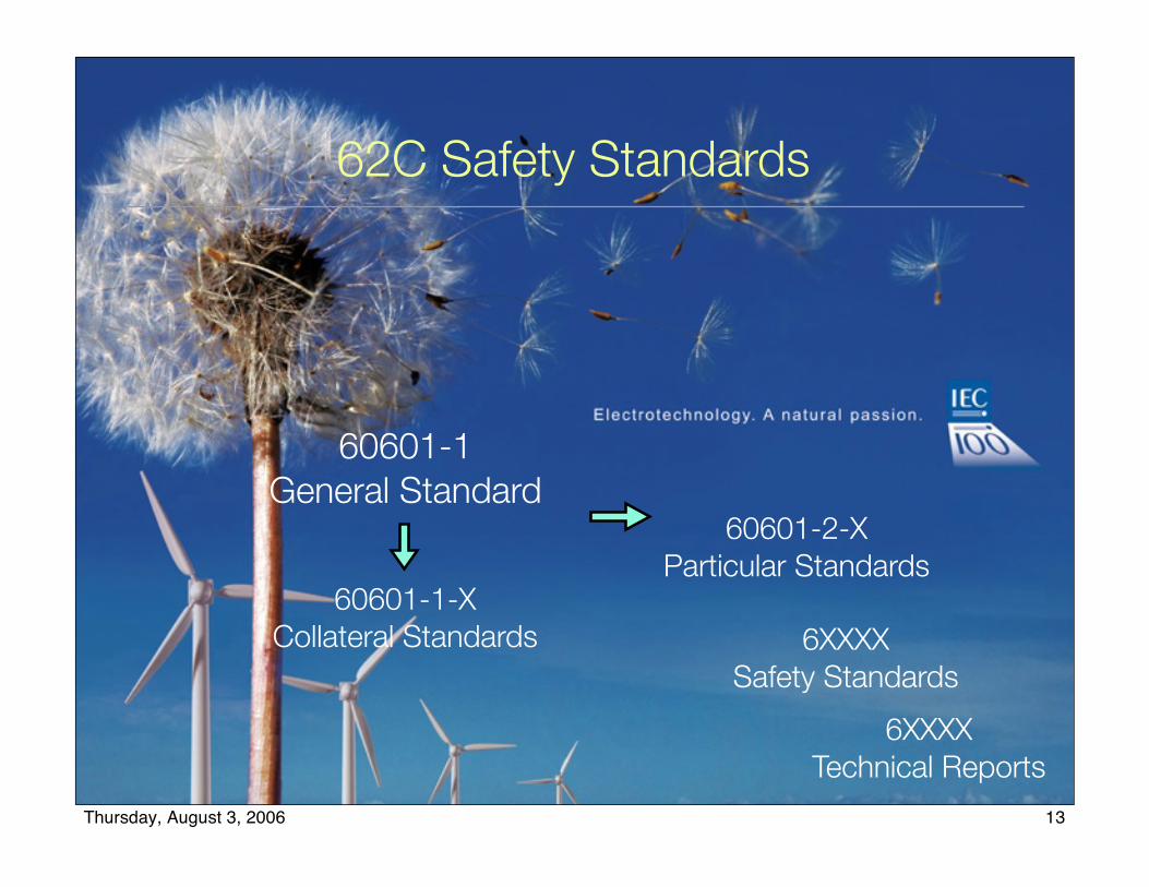
62C Safety Standards
60601-1General Standard
60601-1-XCollateral Standards
60601-2-XParticular Standards
6XXXXSafety Standards
6XXXXTechnical Reports
13Thursday, August 3, 2006
Publications from WG-1
Equipment for Radiation Therapy
Linear AcceleratorsCobalt Units (including Gammaknife)Orthovoltage Treatment UnitsSimulatorsBrachytherapy Remote AfterloadersTreatment Planning SystemsRecord & Verify Systems
14Thursday, August 3, 2006
Safety Standards fromWorking Group 1
60601-2-1: Safety of Linear Accelerators Indicator lights, light field, scales & coordinates Range and speed of motions Function of dose monitoring systems Selection and display of modality, energy,
modifiers, accessories Safety interlocks Leakage radiation Amendment for MLC
15Thursday, August 3, 2006

Defined Terms
201.3.215redundant dose monitoring combinationutilization of two dose monitoring systems where both systems are arranged to terminate irradiation according to the pre-selected number of dose monitor units
16Thursday, August 3, 2006

201.7.7 Indicator lights and push-buttonsa) Colours of indicator lights
Addition:Where indicator lights are used on the TREATMENT CONTROL PANEL (TCP) or other control panels, the colours of the lights shall accord with the following:
RADIATION BEAM "on" yellowREADY STATE greenUrgent action required in response to an unintended state of operation redPREPARATORY STATE other colour
Light emitting diodes (LEDs) are not considered to be indicator lights when
➡ on any one TCP, all indications for which no particular colour is required are given by LEDs of the same colour, and
➡ the indications for which particular colours are required are clearly distinguishable.
17Thursday, August 3, 2006

201.9 Protection against mechanical hazards of me equipment and me systems
b) Rotational movements1) The minimum speed available for each
movement shall not exceed 1o s–1.2) No speed shall exceed 7o s–1.3) When rotating at the speed nearest to, but not
exceeding, 1o s–1, the angle between the position of the moving part at the instant of operating any control to stop the movement and its final position shall not exceed 0,5o ; for speeds faster than 1o s–1, it shall not exceed 3o.
Exception – Requirement 2) above does not apply to the beam limiting system (bls).
18Thursday, August 3, 2006

201.7.1 Marking on the outside of equipment or equipment parts
d) Minimum requirements for marking on EQUIPMENT and on interchangeable parts
Addition:
The dimensions of the GEOMETRICAL RADIATION FIELD at NTD and the distance from the distal end to NTD shall be clearly legible on the outside of all interchangeable and non-adjustable BLDs and ELECTRON BEAM APPLICATORS.
Each manually interchangeable WEDGE FILTER shall be clearly marked to establish its identity.
19Thursday, August 3, 2006

22.4.3 Operation of movements of equipment parts from outside the treatment room
a) It shall be impossible to initiate or maintain movements associated with automatic set-up without continuous personal action by the operator simultaneously on the automatic set-up switch and a switch common to all movements. Each switch, when released, shall be capable of stopping movement; at least one of the switches shall be hard-wired.
20Thursday, August 3, 2006

201.10.1.101.1.1 Dose monitoring systems
The radiation detectors specified in 201.10.1.1.2 shall form part of two dose monitoring systems from whose outputs, displayed as dose monitor units, the absorbed dose at a reference point in the treatment volume can be calculated.The dose monitoring systems shall satisfy the following requirements:
a) malfunctioning of one dose monitoring system shall not affect the correct functioning of the other;
b) failure of any common element that could change the response of either dose monitoring system by more than 5 % shall terminate irradiation;
c) when separate power supplies are used, failure of either supply shall terminate irradiation
21Thursday, August 3, 2006

201.10.1.101.5 Monitoring of distribution of absorbed dose
To protect against gross distortion of the distribution of ABSORBED DOSE, e.g. resulting from failure of fixed ADDED FILTERS, electronic control systems or computer based control systems
a) the RADIATION DETECTORS described in 201.10.1.1.2, or other RADIATION DETECTORS, shall monitor different parts of the radiation beam to detect symmetrical and nonsymmetrical changes of the dose distribution;
b) means shall be provided to TERMINATE IRRADIATION before an additional ABSORBED DOSE of 0,25 Gy is delivered when, at the depth specified for flatness measurements, either the ABSORBED DOSE distribution is distorted by more than 10 %, or the signals from the RADIATION DETECTORS indicate a change greater than 10 %, in the ABSORBED DOSE distribution.
22Thursday, August 3, 2006
201.10.1.103 Absorbed dose rate
c) If, under any fault conditions, the EQUIPMENT can deliver an ABSORBED DOSE RATE at NTD of more than ten times the maximum SPECIFIED in the technical description, a RADIATION BEAM monitoring device, which shall use a circuit independent of the DOSE RATE MONITORING SYSTEM, shall be incorporated on the PATIENT side of the radiation beam distribution system. This shall limit the excess ABSORBED DOSE at any point in the radiation field to less than 4 Gy. The value of the excess ABSORBED DOSE shall be given in the technical description.
23Thursday, August 3, 2006

201.10.1.103 Absorbed dose rate
c) If, under any fault conditions, the EQUIPMENT can deliver an ABSORBED DOSE RATE at NTD of more than ten times the maximum SPECIFIED in the technical description, a RADIATION BEAM monitoring device, which shall use a circuit independent of the DOSE RATE MONITORING SYSTEM, shall be incorporated on the PATIENT side of the radiation beam distribution system. This shall limit the excess ABSORBED DOSE at any point in the radiation field to less than 4 Gy. The value of the excess ABSORBED DOSE shall be given in the technical description.
c) Type test grade A – Statement regarding the
design of radiation beam monitoring device and the
value of the excess absorbed dose that causes
termination of irradiation.
c) Site test grade C – Principle: verification of the
functioning of the radiation beam monitoring device
by generating or simulating excess electron beam
current.
23Thursday, August 3, 2006

PRO TECTIVE SHIELDING
1 m
1 m
TARG ET/ELECTRO N RADIATION window
ELECTRO N path
Non-adjustable primaryBEAM LIMITING DEVICE
NO RMAL TREATMENT
DISTANCE
ISO CEN TRE
Adjustable BEAM
LIMITING DEVICEPATIENT plane Boundary for measurement of
LEAKAGE RADIATION outside
the PATIENT plane
(29.4.1 and 29.4.2)
GEO METRICAL RADIATIO N FIELD due to
an ELECTRON BEAM LIM ITIN G DEVICE
Area M for 29.3.1.1
and area M (or M10
) for 29.3.1.2
29.3.2, 29.3.3, 29.3.4
Radius 2 m
REFERENCE AXIS
ELECTRON gun
IEC 8
Measurement of Leakage Radiation
24Thursday, August 3, 2006

Jaw Transmission
24 points for measurement
by RADIATION DETECTO R
Fully opened X-axisBEAM LIMITING DEVICES
6 equispaced axes forRADIATION DETECTO R
measurements
Any residual aperture closed by
at least two TENTH-VALUE LAYERS
of X -RADIATIO N absorbing material
Periphery of
area M Fully closed Y-axisBEAM LIMITING DEVICES
REFERENCE AXIS
R2
= 0,500 R0
R1
= 0,866 R0
R0
IEC 816/98
25Thursday, August 3, 2006

Proposed new safety clauses for SRS
Positioning accuracy
Strain caused by moving parts
Collision avoidance
26Thursday, August 3, 2006

Proposed new safety clauses for IMRT
Incorrect field shape
Incorrect MU for part of field
Record and verify capability
Neutron dose
Whole body dose
27Thursday, August 3, 2006
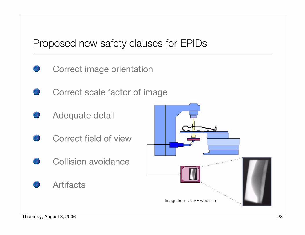
Proposed new safety clauses for EPIDs
Correct image orientation
Correct scale factor of image
Adequate detail
Correct field of view
Collision avoidance
Artifacts
Image from UCSF web site
28Thursday, August 3, 2006

Proposed new safety clauses for IGRT
Registration of images
Accuracy of movement of patient support
Movement of MLC in response to imaging
Movement of gantry in response to imaging
...
29Thursday, August 3, 2006

Additional Safety Standards
62083: Safety of radiotherapy treatment planning systems
62274: Safety of radiotherapy record and verify systems
30Thursday, August 3, 2006

IEC 62083 - Safe Operation of Treatment Planning Systems
• Format of displays, units, date & time
• Data limits, transfer
• Saving and archiving data
• Equipment and source model• Patient model
• Treatment planning
• Dose calculation
• Treatment plan report
31Thursday, August 3, 2006
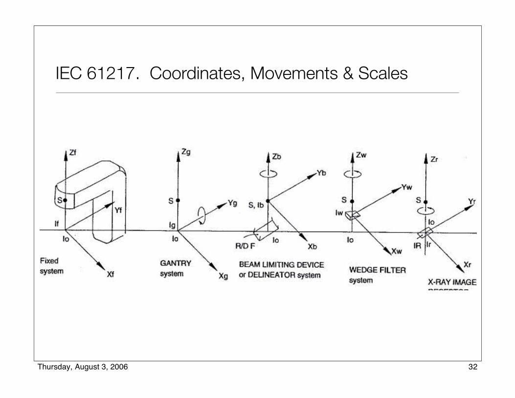
IEC 61217. Coordinates, Movements & Scales
32Thursday, August 3, 2006

IEC 61217. Coordinates, Movements & Scales
33Thursday, August 3, 2006
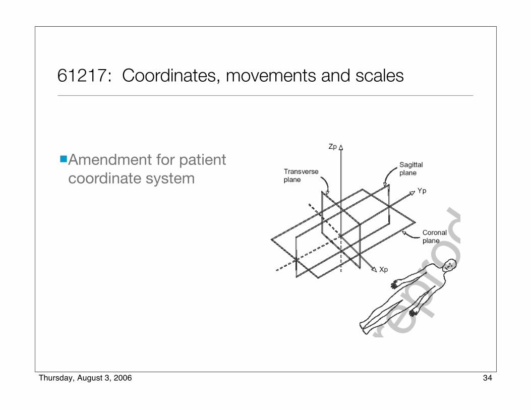
61217: Coordinates, movements and scales
Amendment for patient coordinate system
34Thursday, August 3, 2006

Performance Standards from WG-1
61168: Radiation therapy simulators - Functional performance characteristics
60976: Medical electron accelerators - Functional performance characteristics
60977: Guidelines for functional performance characteristics
35Thursday, August 3, 2006

IEC 60976. Medical electron accelerators - Functional performance characteristics
“... specifies test procedures for the determination and disclosure of functional performance characteristics,
knowledge of which is deemed necessary for proper application and use of a medical ELECTRON ACCELERATOR and which are to be declared in the ACCOMPANYING DOCUMENTS together with the greatest deviation or variation to be expected under specific conditions in NORMAL USE.”
36Thursday, August 3, 2006

6.4 Dependence on angular positions
6.4.1 Information to the USER
[R is dose per MU]
The ACCOMPANYING DOCUMENTS shall state the maximum differences between the maximum value and the minimum value of the ratio R for both X-RADIATION and ELECTRON RADIATION when the equipment is placed in different positions through the full range of rotations.
The maximum differences shall be expressed as percentages of the mean value of R for bothX-RADIATION and ELECTRON RADIATION.
37Thursday, August 3, 2006

IEC 60977. Guidelines for functional performance characteristics
Provides a suggested format for the reporting of performance characteristics
Provides suggested performance levels
38Thursday, August 3, 2006

6.4 Dependence on angular positions
Maximum difference between the maximum and minimum values of R over the full angular ranges of the GANTRY and BEAM LIMITING SYSTEM ...
X-RADIATION
Declared maximum difference ... ________ % (3)
[Where R is the average dose per MU]
39Thursday, August 3, 2006
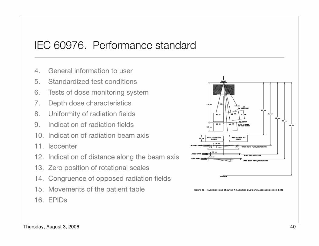
4. General information to user
5. Standardized test conditions
6. Tests of dose monitoring system
7. Depth dose characteristics
8. Uniformity of radiation fields
9. Indication of radiation fields
10. Indication of radiation beam axis
11. Isocenter
12. Indication of distance along the beam axis
13. Zero position of rotational scales
14. Congruence of opposed radiation fields
15. Movements of the patient table
16. EPIDs
IEC 60976. Performance standard
40Thursday, August 3, 2006
61852: Medical electrical equipment - Digital imaging and communications in medicine (DICOM) - Radiotherapy objects
61859: Guidelines for radiotherapy treatment rooms design
Additional Performance Standards
41Thursday, August 3, 2006

Gestation of an IEC Standard
Typical for a new standard to take at least 5 years in developmentIEC requires standards to be revised every 5 years; review begins 3 years after publication
General Standard has been revised; will require revision of all particular standards
42Thursday, August 3, 2006

Thank You!
43Thursday, August 3, 2006