Embed Size (px)
Citation preview
Automation in Construction 19 (2010) 750–761
Contents lists available at ScienceDirect
Automation in Construction
j ourna l homepage: www.e lsev ie r.com/ locate /autcon
A physics-based simulation approach for cooperative erection activities
Hung-Lin Chi, Shih-Chung Kang ⁎Dept. of Civil Engineering, National Taiwan University, Taipei City 10617, Taiwan
⁎ Corresponding author.E-mail addresses: [email protected] (H.-L. Chi), sckan
0926-5805/$ – see front matter © 2010 Elsevier B.V. Adoi:10.1016/j.autcon.2010.03.004
a b s t r a c t
a r t i c l e i n f oArticle history:Accepted 1 March 2010
Keywords:Cooperative erection activitiesRigid body dynamicsForward kinematicsConstruction cranePhysics-based simulationErection planningVirtual realityRobotics
Cooperative erection activities are critical to projects which involve the erection of heavy loads or theinstallation of special equipment. Detailed simulation on computer prior to construction can identifyconstructability problems, and subsequently avoided during actual erections. This paper describes anintegrated approach for simulating the detailed motions of cranes. This research develops a physics-basedmodel that follows the principle of closed-form forward kinematics and constraint-based dynamics topresent the dual-crane mechanism mathematically — a non-trivial task. This model can be used to analyzethe inputs from the users (i.e. virtual crane operators) and simultaneously compute the cables sway andreaction of collisions. We also implemented the model on computer and developed a simulation system,Erection Director, to render realistic cooperative erection activities. A demonstration of simulating two-cranelift has been built and three performance tests including a small building (840 elements), a medium building(1937 elements) and a large building (2682 elements) validate the feasibility of the proposed approach. Thetest results indicate that Erection Director can support real-time and physics-based visualization ofcooperative erections.
[email protected] (S.-C. Kang).
ll rights reserved.
© 2010 Elsevier B.V. All rights reserved.
1. Introduction
Cooperative erection activities are very common in modernconstruction projects, especially for plant constructions, in which atypical yet critical task is the installation of the major equipment. Theinstallation process usually involves the erection of extremely heavyequipment. Even though a detailed plan is usually developed to levelthe erection loads, the weight of a single erection can be as high as1300 t on some larger plant constructions. It is efficient to completesuch erection tasks using multiple and relatively cheap cranescooperatively rather than specifying a single more expensive crane[1,2]. In most cases, two cranes, usually a major crane and an assistingcrane, work cooperatively to complete such an erection activity.
In two-crane cases, erection planners need to consider three majorissues to properly arrange and plan cooperative erection activities. First,they need to maintain the loads of the cranes within safe workingcapacities for the duration of the erection processes. However, withoutthe use of an effective computational method, it is onerous to analyzeand calculate the loads on each individual crane. Most planners simplyrely on their experience or estimate the loads using static mechanics.Due to a lackof reliable simulations, the erectionplans are usually overlyconservative in order to reduce the possibility of dealing withunforeseen situations.
Avoiding collision is the second issue planners need to considercarefully. Since most of the cooperative erections take place aroundhalf-way into the project, the building structures are already partiallybuilt thus the two cranes need to cooperate to transport theequipment into the building. Every part of both the equipment andthe cranes must not collide with any object of or in the partially builtstructure. This requires the consideration of the 3D geometricalrelationship between the cranes' configurations, the rigging object,and the crane cables sway. In current practice, planners rely onexperience or a simplified model that preserves working space to dealwith this problem.
The third consideration is the attitude (i.e. position and orientationin space) of the equipment for the entirety of the erection processes.The equipment needs to follow a specific path or sequence to betransported safely to the location of installation, especially forprocesses performed in an environment with many obstacles. Twocranes need to work cooperatively to maintain the equipment onpredefined paths. After reaching the installation location, theequipment needs to be maintained at a certain attitude untilinstallation commences.
To handle such complexities, we need to develop a simulation thatcan realistically reflect actual erection scenarios. This simulationshould not only include the visual presentation of erection processes,but also the related physical information, such as force feedback, cablesways, and collision behaviors. Such a simulation will be workable inreal time and would facilitate erection planners in generating safe,efficient, and collision-free paths for cooperative erection activities inthe future.
751H.-L. Chi, S.-C. Kang / Automation in Construction 19 (2010) 750–761
2. Related work
Many previous studies are aimed at realizing the simulation oferection activities while considering the safety loading range, collisionavoidance, and transportation attitude [3,4]. In the field of trainingsimulator development, SimLog1 and CMLabs Corporation2 provideadvanced devices for crane operation training. These are assistanttools that help novice crane operators practice their skills usingseveral different training scenarios, each customized to prepareoperators to sit for a particular certification examination. Themovements of the virtual crane are directed by user manipulationand the reactions reflect actual physical behaviors.
Many construction consulting firms have developed adds-on orexternal modules for existing visualization tools to simulate cooper-ative erections. An engineering consulting corporation, Chung-Ting(CTCI), developed an add-on for the AutoCAD3 systemwhich providesa visualization interface for erection simulations. A product from JGCCorporation4 also provides a virtual environment with variousviewing interfaces for visualizing the planning movements. Both ofthese products can automatically generate animations of rigging pathsfor erection activities.
Some related works can also be found in academia. Researchersusually use automated approaches that integrate modern searchprocesses [5,6] or heuristic technologies from the field of numericalkinematics [7] and motion planning [8] to generate the movements ofcooperative virtual cranes automatically. Users need to set up theinitial conditions of a construction jobsite and the software deter-mines the most efficient yet safe and collision-free paths for use insimulating the erection activities.
In popular software, such as 3D Studio Max [9] and Maya [10],semi-automation is used to produce animation. Users set key framesso that the frames in-between can be interpolated. Such technology isalso feasible for planning the movements of erection processes.
These approaches and technologies are capable of simulatingdifferent aspects of erection activities, but there should be appropriateways of integrating these methods to negotiate all of the three majorissues mentioned in Introduction section. Therefore, due to thecomplexity of the combinations of the cranes' motions and issues ofrealism, the challenge in the simulation of cooperative erection is todevelop a methodology for generating accurate, feasible, andcollision-free motion paths that represent the complex interactionsbetween cooperating cranes, and to perform visualizations in real-time.
3. Research goals
This research aims at utilizing physics-based animation methods,which are widely used in game physics and training simulators, togenerate detailed cooperative erection activities in a virtual environ-ment. Unlike game environment which focus more on the visualstimulation instead of precision. Our work, on the contrary,emphasizes the precision of the simulation. By using these methodsand real construction cases, it should be more flexible to build up thesimulation scenarios and at themean time to show them at acceptableframe rate per second. The simulation is not just for training purposebut focuses on the evaluations of erection plans. Work-items need to
1 Simlog, Mobile Crane Personal Simulator, Retrieved June 25, 2007, from http://www.simlog.com/personal-crane.html.
2 CMLabs, Vortex Training Simulators, Retrieved April 2, 2007, from http://www.vortexsim.com.
3 Autodesk, AutoCAD, Retrieved June 25, 2007, from http://usa.autodesk.com/adsk/servlet/index?siteID=123112&id=2704278.
4 JGC, 4D CAD System, Retrieved June 25, 2007, from http://www.jgc.co.jp/en/03srvs/07const/02e_const/4d_cad.html.
be simulated as accurately as possible in order to find potentialproblems before physical operations commence. In order to retainflexibility and generality in solving these problems, a prototypesystem for visualizing the simulations has been developed andevaluated to perform the simulations.
4. Existing methods for generating physics-based simulation
To simulate high-risk erection activities, the integration of physics-based simulation methods plays a significant role in this research.Physics-based simulation methods utilize various theoretical laws ofphysics and a variety of mathematics; combined they describe amathematical model of the real world.
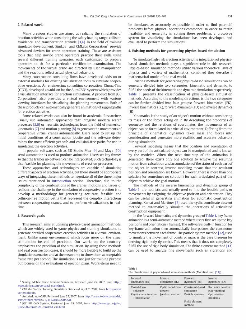
Existing methods for generating physics-based simulations can begenerally divided into two categories: kinematic and dynamic, tofulfill the needs of the kinematic and dynamic simulation respectively.Table 1 presents the classification of physics-based simulationmethods. According to the modeling directions, is the two categoriescan be further divided into four groups: forward kinematics (FK),inverse kinematics (IK), forward dynamics (FD) and inverse dynamics(ID).
Kinematics is the study of an object's motion without consideringits mass or the forces acting on it. By describing the properties ofgeometry and the relations of coordinates, the movements of anobject can be formulated in a virtual environment. Differing from theprinciple of kinematics, dynamics takes mass and forces intoconsideration and generates more realistic and accurate behaviorsduring simulation.
Forward modeling means that the position and orientation ofevery part of the articulated-object can be manipulated and is knownby the modeler. When the next time-step of the animation isgenerated, there exists only one solution to achieve the resultingmotion from calculation and accumulation of the status of each part ofthe object. In contrast, inverse modeling means that the resultantposition and orientation are known. However, there is more than onesolution (or sometimes no solution) for each articulated part of theobject to achieve the goal motion.
The methods of the inverse kinematics and dynamics group ofTable 1, are heuristic and usually used to find the feasible paths ormovements by assigning the objective position and orientation. Theycan be useful in generating animation for automatic constructionplanning. Kamat and Martinez [7] used the cyclic coordinate descentmethod to automatically simulate the operations of articulatedconstruction equipment.
In the forward kinematics and dynamics group of Table 1, key frameanimation is a semi-automatic method where users first set up the keypositions and orientations (frames). The software's built-in function forkey-frame animation then automatically interpolates the continuousmovements between each frame. The particle systemmethod [12], usedto simulate the movement of points of mass, is the base theorem forderiving rigid body dynamics. This means that it does not completelyfulfill the use of rigid body simulation. The finite element method [13]can be used to analyze fine movements such as vibrations and
Table 1The classification of physics-based simulation methods (Modified from [11]).
Forwardkinematics (FK)
Inversekinematics (IK)
Forwarddynamics (FD)
Inversedynamics (ID)
Closed-formsolutions
Cyclic coordinatedescent
Constraint-basedsimulation
Recursive newtoneuler method
Key-frame animation(interpolation)
Jacobian method Particle systems Optimizationproblems
Finite elementmethod
752 H.-L. Chi, S.-C. Kang / Automation in Construction 19 (2010) 750–761
deformations of cranes. However, a set of simplifying assumptions isrequired to be applied on the conditions, and deformations on rigidequipment are relatively small.
Unlike automatic animation, this research is focused on operational-level simulation and controllable manipulations. In other words, ittargets the situation where the crane operator manipulates the virtualcrane without knowing the exact reaction of the crane when the action
Fig. 1. The architecture of the nu
is executed. For example, the operator can control a gear to rotatethe boom of the crane, but the user would not know to where thehook of the cranewill swing. For these reasons, the remainingmethods,closed-form solutions and constraint-based simulations, are appropri-ate approaches to numerically modeling a crane. They will be calledclosed-form forward kinematics and constraint-based rigid bodydynamics, and are explained in the following sections.
5. Single crane modeling
A two-stepmethodology, as will be described, is required to develop a cooperative erection simulation. The first step is single cranemodeling.This describes a numerical modeling method using the principle of closed-form forward kinematics and constraint-based rigid body dynamics.The second step is to derive the modeling method for a cooperative dual-crane scenario.
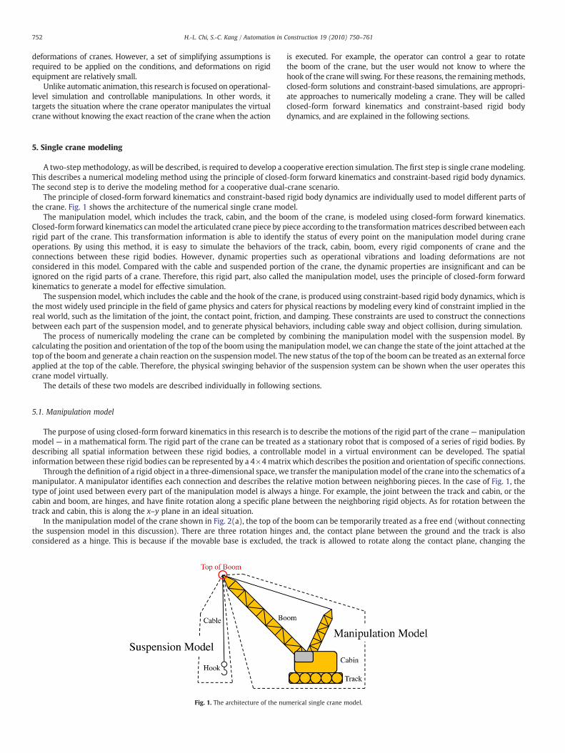
The principle of closed-form forward kinematics and constraint-based rigid body dynamics are individually used to model different parts ofthe crane. Fig. 1 shows the architecture of the numerical single crane model.
The manipulation model, which includes the track, cabin, and the boom of the crane, is modeled using closed-form forward kinematics.Closed-form forward kinematics canmodel the articulated crane piece by piece according to the transformationmatrices described between eachrigid part of the crane. This transformation information is able to identify the status of every point on the manipulation model during craneoperations. By using this method, it is easy to simulate the behaviors of the track, cabin, boom, every rigid components of crane and theconnections between these rigid bodies. However, dynamic properties such as operational vibrations and loading deformations are notconsidered in this model. Compared with the cable and suspended portion of the crane, the dynamic properties are insignificant and can beignored on the rigid parts of a crane. Therefore, this rigid part, also called the manipulation model, uses the principle of closed-form forwardkinematics to generate a model for effective simulation.
The suspension model, which includes the cable and the hook of the crane, is produced using constraint-based rigid body dynamics, which isthe most widely used principle in the field of game physics and caters for physical reactions by modeling every kind of constraint implied in thereal world, such as the limitation of the joint, the contact point, friction, and damping. These constraints are used to construct the connectionsbetween each part of the suspension model, and to generate physical behaviors, including cable sway and object collision, during simulation.
The process of numerically modeling the crane can be completed by combining the manipulation model with the suspension model. Bycalculating the position and orientation of the top of the boom using the manipulation model, we can change the state of the joint attached at thetop of the boom and generate a chain reaction on the suspensionmodel. The new status of the top of the boom can be treated as an external forceapplied at the top of the cable. Therefore, the physical swinging behavior of the suspension system can be shown when the user operates thiscrane model virtually.
The details of these two models are described individually in following sections.
5.1. Manipulation model
The purpose of using closed-form forward kinematics in this research is to describe the motions of the rigid part of the crane—manipulationmodel — in a mathematical form. The rigid part of the crane can be treated as a stationary robot that is composed of a series of rigid bodies. Bydescribing all spatial information between these rigid bodies, a controllable model in a virtual environment can be developed. The spatialinformation between these rigid bodies can be represented by a 4×4matrix which describes the position and orientation of specific connections.
Through the definition of a rigid object in a three-dimensional space, we transfer themanipulationmodel of the crane into the schematics of amanipulator. A manipulator identifies each connection and describes the relative motion between neighboring pieces. In the case of Fig. 1, thetype of joint used between every part of the manipulation model is always a hinge. For example, the joint between the track and cabin, or thecabin and boom, are hinges, and have finite rotation along a specific plane between the neighboring rigid objects. As for rotation between thetrack and cabin, this is along the x–y plane in an ideal situation.
In the manipulation model of the crane shown in Fig. 2(a), the top of the boom can be temporarily treated as a free end (without connectingthe suspension model in this discussion). There are three rotation hinges and, the contact plane between the ground and the track is alsoconsidered as a hinge. This is because if the movable base is excluded, the track is allowed to rotate along the contact plane, changing the
merical single crane model.
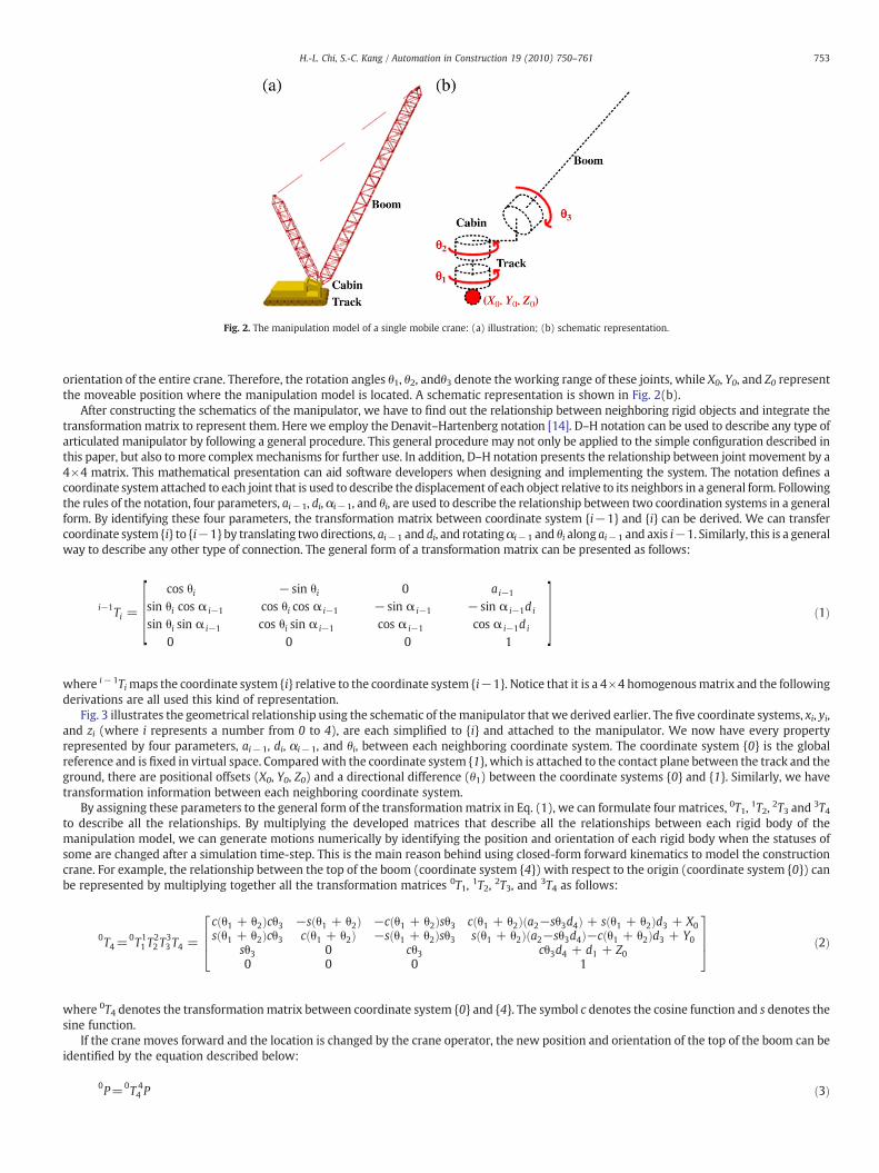
Fig. 2. The manipulation model of a single mobile crane: (a) illustration; (b) schematic representation.
753H.-L. Chi, S.-C. Kang / Automation in Construction 19 (2010) 750–761
orientation of the entire crane. Therefore, the rotation angles θ1, θ2, andθ3 denote the working range of these joints, while X0, Y0, and Z0 representthe moveable position where the manipulation model is located. A schematic representation is shown in Fig. 2(b).
After constructing the schematics of the manipulator, we have to find out the relationship between neighboring rigid objects and integrate thetransformation matrix to represent them. Here we employ the Denavit–Hartenberg notation [14]. D–H notation can be used to describe any type ofarticulated manipulator by following a general procedure. This general procedure may not only be applied to the simple configuration described inthis paper, but also to more complex mechanisms for further use. In addition, D–H notation presents the relationship between joint movement by a4×4 matrix. This mathematical presentation can aid software developers when designing and implementing the system. The notation defines acoordinate system attached to each joint that is used to describe the displacement of each object relative to its neighbors in a general form. Followingthe rules of the notation, four parameters, ai−1, di, αi−1, and θi, are used to describe the relationship between two coordination systems in a generalform. By identifying these four parameters, the transformation matrix between coordinate system {i−1} and {i} can be derived. We can transfercoordinate system {i} to {i−1} by translating two directions, ai−1 and di, and rotatingαi−1 and θi along ai−1 and axis i−1. Similarly, this is a generalway to describe any other type of connection. The general form of a transformation matrix can be presented as follows:
i−1Ti = ½ cos θi − sin θi 0 ai−1
sin θi cos α i−1 cos θi cos α i−1 − sin α i−1 − sin α i−1di
sin θi sin α i−1 cos θi sin α i−1 cos α i−1 cos α i−1di
0 0 0 1� ð1Þ
where i−1Timaps the coordinate system {i} relative to the coordinate system {i−1}. Notice that it is a 4×4 homogenousmatrix and the followingderivations are all used this kind of representation.
Fig. 3 illustrates the geometrical relationship using the schematic of themanipulator that we derived earlier. The five coordinate systems, xi, yi,and zi (where i represents a number from 0 to 4), are each simplified to {i} and attached to the manipulator. We now have every propertyrepresented by four parameters, ai−1, di, αi−1, and θi, between each neighboring coordinate system. The coordinate system {0} is the globalreference and is fixed in virtual space. Comparedwith the coordinate system {1}, which is attached to the contact plane between the track and theground, there are positional offsets (X0, Y0, Z0) and a directional difference (θ1) between the coordinate systems {0} and {1}. Similarly, we havetransformation information between each neighboring coordinate system.
By assigning these parameters to the general form of the transformation matrix in Eq. (1), we can formulate four matrices, 0T1, 1T2, 2T3 and 3T4to describe all the relationships. By multiplying the developed matrices that describe all the relationships between each rigid body of themanipulation model, we can generate motions numerically by identifying the position and orientation of each rigid body when the statuses ofsome are changed after a simulation time-step. This is the main reason behind using closed-form forward kinematics to model the constructioncrane. For example, the relationship between the top of the boom (coordinate system {4}) with respect to the origin (coordinate system {0}) canbe represented by multiplying together all the transformation matrices 0T1, 1T2, 2T3, and 3T4 as follows:
0T4=0T1
1T22T
33T4 =
c θ1 + θ2ð Þcθ3 −s θ1 + θ2ð Þ −c θ1 + θ2ð Þsθ3 c θ1 + θ2ð Þ a2−sθ3d4ð Þ + s θ1 + θ2ð Þd3 + X0s θ1 + θ2ð Þcθ3 c θ1 + θ2ð Þ −s θ1 + θ2ð Þsθ3 s θ1 + θ2ð Þ a2−sθ3d4ð Þ−c θ1 + θ2ð Þd3 + Y0
sθ3 0 cθ3 cθ3d4 + d1 + Z00 0 0 1
2664
3775 ð2Þ
where 0T4 denotes the transformation matrix between coordinate system {0} and {4}. The symbol c denotes the cosine function and s denotes thesine function.
If the crane moves forward and the location is changed by the crane operator, the new position and orientation of the top of the boom can beidentified by the equation described below:
0P=0T 44 P ð3Þ
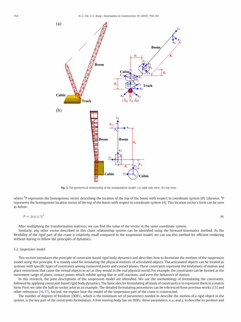
Fig. 3. The geometrical relationship of the manipulation model: (a) right side view; (b) top view.
754 H.-L. Chi, S.-C. Kang / Automation in Construction 19 (2010) 750–761
where 0P represents the homogenous vector describing the location of the top of the boom with respect to coordinate system {0}. Likewise, 4Prepresents the homogenous location vector of the top of the boom with respect to coordinate system {4}. This location vector's form can be seenas below:
P = x; y; z;1½ �T : ð4Þ
After multiplying the transformation matrices, we can find the value of the vector in the same coordinate system.Similarly, any other vector described in this chain relationship system can be identified using the forward kinematics method. As the
flexibility of the rigid part of the crane is relatively small compared to the suspension model, we can use this method for efficient renderingwithout having to follow the principles of dynamics.
5.2. Suspension model
This section introduces the principle of constraint-based rigid body dynamics and describes how to formulate the motions of the suspensionmodel using this principle. It is mainly used for simulating the physical motions of articulated objects. The articulated objects can be treated assystems with specific types of constraints among connected joints and contact planes. These constraints represent the limitations of motion andplace restrictions that cause the virtual objects to act as they would in the real physical world. For example, the constraints can be formed as themovement range of joints, contact points which exhibit spring-like or stiff reactions, and even the behaviors of motors.
In this research, the joint descriptions of the suspension model are identified. We use the methodology of formulating the constraints,followed by applying constraint-based rigid body dynamics. The basic idea for formulating all kinds of constraints is to represent them in amatrixform. First, we take the ball-in-socket joint as an example. The detailed formulating procedures can be referenced from previous works [15] andother references [16,17]. Second, we explain how the model of the suspension part of the crane is constructed.
The number of degrees of freedom (DOFs), which is the minimum set of parameters needed to describe the motion of a rigid object in thesystem, is the key part of the constraints formulation. A free moving body has six DOFs: three parameters, x, y, and z, to describe its position and
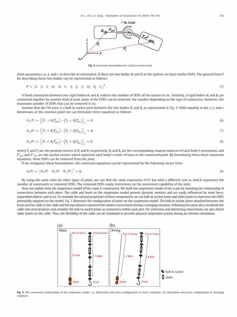
Fig. 4. Constraint formulation for a ball-in-socket joint.
755H.-L. Chi, S.-C. Kang / Automation in Construction 19 (2010) 750–761
three parameters, ω, ψ, and κ to describe its orientation. If there are two bodies Bi and Bj in the system, we have twelve DOFs. The general form Pfor describing these two bodies can be represented as follows:
P = xi yi zi ωi ψi κi xj yj zj ωj ψj κj� �T
: ð5Þ
A fixed connection between two rigid bodies Bi and Bj reduces the number of DOFs of the system to six. Similarly, if rigid bodies Bi and Bj areconnected together by another kind of joint, some of the DOFs can be removed, the number depending on the type of connection. However, themaximum number of DOFs that can be removed is six.
Assume that the l'th joint is a ball-in-socket joint between the two bodies Bi and Bj as represented in Fig. 4. With equality in the x, y, and zdimensions at the common point we can formulate three equations as follows:
Φx Pð Þ = Pi + RiPianc
� �− Pj + RjP
janc
� �h ix= 0 ð6Þ
Φy Pð Þ = Pi + RiPianc
� �− Pj + RjP
janc
� �h iy= 0 ð7Þ
Φz Pð Þ = Pi + RiPianc
� �− Pj + RjP
janc
� �h iz= 0 ð8Þ
where Pi and Pj are the position vectors of Bi and Bj respectively, Ri and Rj are the corresponding rotation matrices of each body's orientation, andP i
anc and P janc are the anchor vectors which represent each body's center of mass to the connected point. By formulating these three constraint
equations, three DOFs can be removed from the joint.If we reorganize these formulations, the constraint equations can be represented by the following vector form:
Φ Pð Þ = Φx Pð Þ Φy Pð Þ Φz Pð Þ� �T = 0: ð9Þ
By using the same rules for other types of joints, we can find the same expression Φ(P) but with a different row m, which represents thenumber of constraints or removed DOFs. The removed DOFs imply restrictions on the movement capability of the joint.
Nowwe explain how the suspension model of the crane is constructed. We built the suspension model of the crane by imitating the relationship ofconnections between each piece. The cable and hook on the suspension model present dynamic motions and are easily influenced by wind force,suspended objects, and so on. To simulate the natural properties of these components, we use ball-in-socket joints and slider joints to represent the DOFspotentially required on the model. Fig. 5 illustrates the configuration of joints on the suspension model. The ball-in-socket joints attached between thehookand the cable or the cable and the topof boomrepresent the relativemovements during a swinging situation. Following the same idea,wedivide thecable into several pieces and consider the ball-in-socket joints as connectors within each part. For extension and shorteningmovements, we also attachslider joints on the cable. Thus, the flexibility of the cable can be simulated to provide physical suspended actions during an erection simulation.
Fig. 5. The connection relationships of the suspension model: (a) illustration and joints configuration in static condition; (b) illustration and joints configuration in swingingcondition.
756 H.-L. Chi, S.-C. Kang / Automation in Construction 19 (2010) 750–761
6. Dual-crane modeling
In this section, we present the method for modeling the dual-cranebuilding cooperative erections. Dual-crane cooperation usually involveshigh risk and specialized construction events on a jobsite. In thisresearch, dual-crane cooperative erection refers to an erection taskperformed concurrently by two cranes for a specific, unusual, and large-scaled piece of construction equipment such as a petroleum tank. Thiskind of erection activity requires the operators to manipulate bothcranes synchronously to keep the rigging object stable during theerection cycle. This requires not only advanced operating skills of asingle crane, but also the careful coordination of the two cranes.
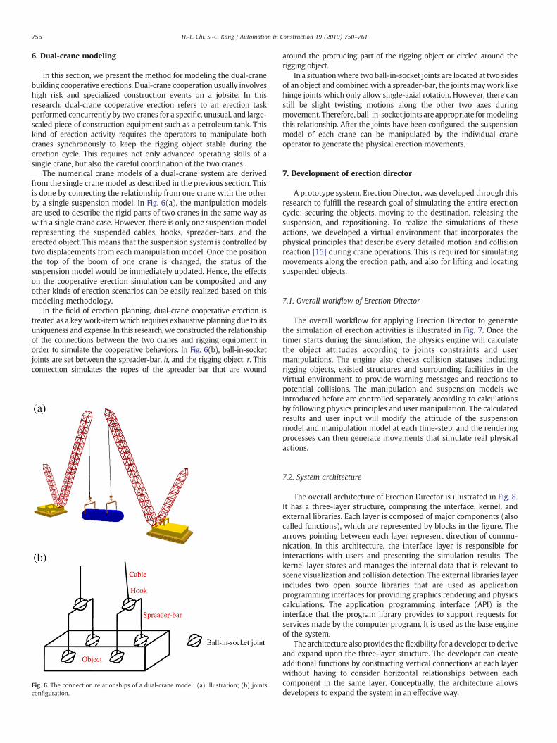
The numerical crane models of a dual-crane system are derivedfrom the single crane model as described in the previous section. Thisis done by connecting the relationship from one crane with the otherby a single suspension model. In Fig. 6(a), the manipulation modelsare used to describe the rigid parts of two cranes in the same way aswith a single crane case. However, there is only one suspensionmodelrepresenting the suspended cables, hooks, spreader-bars, and theerected object. This means that the suspension system is controlled bytwo displacements from each manipulation model. Once the positionthe top of the boom of one crane is changed, the status of thesuspension model would be immediately updated. Hence, the effectson the cooperative erection simulation can be composited and anyother kinds of erection scenarios can be easily realized based on thismodeling methodology.
In the field of erection planning, dual-crane cooperative erection istreated as a keywork-itemwhich requires exhaustive planning due to itsuniqueness and expense. In this research,we constructed the relationshipof the connections between the two cranes and rigging equipment inorder to simulate the cooperative behaviors. In Fig. 6(b), ball-in-socketjoints are set between the spreader-bar, h, and the rigging object, r. Thisconnection simulates the ropes of the spreader-bar that are wound
Fig. 6. The connection relationships of a dual-crane model: (a) illustration; (b) jointsconfiguration.
around the protruding part of the rigging object or circled around therigging object.
In a situationwhere two ball-in-socket joints are located at two sidesof an object and combinedwith a spreader-bar, the jointsmaywork likehinge joints which only allow single-axial rotation. However, there canstill be slight twisting motions along the other two axes duringmovement. Therefore, ball-in-socket joints are appropriate formodelingthis relationship. After the joints have been configured, the suspensionmodel of each crane can be manipulated by the individual craneoperator to generate the physical erection movements.
7. Development of erection director
A prototype system, Erection Director, was developed through thisresearch to fulfill the research goal of simulating the entire erectioncycle: securing the objects, moving to the destination, releasing thesuspension, and repositioning. To realize the simulations of theseactions, we developed a virtual environment that incorporates thephysical principles that describe every detailed motion and collisionreaction [15] during crane operations. This is required for simulatingmovements along the erection path, and also for lifting and locatingsuspended objects.
7.1. Overall workflow of Erection Director
The overall workflow for applying Erection Director to generatethe simulation of erection activities is illustrated in Fig. 7. Once thetimer starts during the simulation, the physics engine will calculatethe object attitudes according to joints constraints and usermanipulations. The engine also checks collision statuses includingrigging objects, existed structures and surrounding facilities in thevirtual environment to provide warning messages and reactions topotential collisions. The manipulation and suspension models weintroduced before are controlled separately according to calculationsby following physics principles and user manipulation. The calculatedresults and user input will modify the attitude of the suspensionmodel and manipulation model at each time-step, and the renderingprocesses can then generate movements that simulate real physicalactions.
7.2. System architecture
The overall architecture of Erection Director is illustrated in Fig. 8.It has a three-layer structure, comprising the interface, kernel, andexternal libraries. Each layer is composed of major components (alsocalled functions), which are represented by blocks in the figure. Thearrows pointing between each layer represent direction of commu-nication. In this architecture, the interface layer is responsible forinteractions with users and presenting the simulation results. Thekernel layer stores and manages the internal data that is relevant toscene visualization and collision detection. The external libraries layerincludes two open source libraries that are used as applicationprogramming interfaces for providing graphics rendering and physicscalculations. The application programming interface (API) is theinterface that the program library provides to support requests forservices made by the computer program. It is used as the base engineof the system.
The architecture also provides theflexibility for a developer to deriveand expand upon the three-layer structure. The developer can createadditional functions by constructing vertical connections at each layerwithout having to consider horizontal relationships between eachcomponent in the same layer. Conceptually, the architecture allowsdevelopers to expand the system in an effective way.
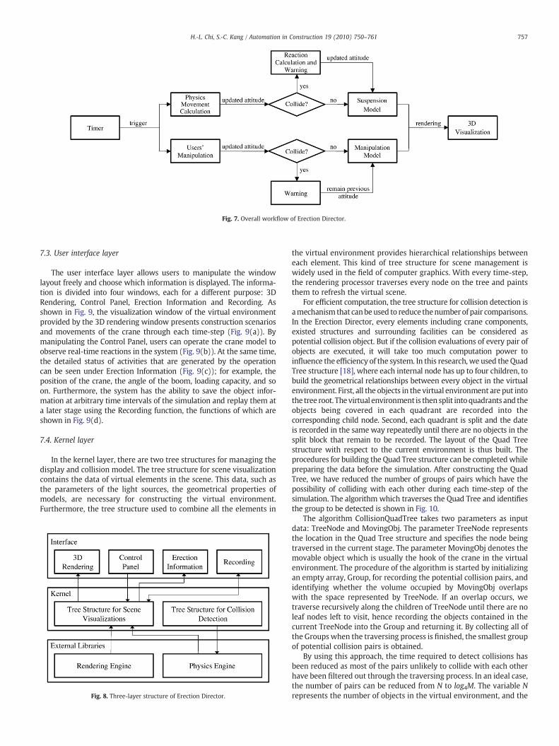
Fig. 7. Overall workflow of Erection Director.
757H.-L. Chi, S.-C. Kang / Automation in Construction 19 (2010) 750–761
7.3. User interface layer
The user interface layer allows users to manipulate the windowlayout freely and choose which information is displayed. The informa-tion is divided into four windows, each for a different purpose: 3DRendering, Control Panel, Erection Information and Recording. Asshown in Fig. 9, the visualization window of the virtual environmentprovided by the 3D rendering window presents construction scenariosand movements of the crane through each time-step (Fig. 9(a)). Bymanipulating the Control Panel, users can operate the crane model toobserve real-time reactions in the system (Fig. 9(b)). At the same time,the detailed status of activities that are generated by the operationcan be seen under Erection Information (Fig. 9(c)); for example, theposition of the crane, the angle of the boom, loading capacity, and soon. Furthermore, the system has the ability to save the object infor-mation at arbitrary time intervals of the simulation and replay them ata later stage using the Recording function, the functions of which areshown in Fig. 9(d).
7.4. Kernel layer
In the kernel layer, there are two tree structures for managing thedisplay and collision model. The tree structure for scene visualizationcontains the data of virtual elements in the scene. This data, such asthe parameters of the light sources, the geometrical properties ofmodels, are necessary for constructing the virtual environment.Furthermore, the tree structure used to combine all the elements in
Fig. 8. Three-layer structure of Erection Director.
the virtual environment provides hierarchical relationships betweeneach element. This kind of tree structure for scene management iswidely used in the field of computer graphics. With every time-step,the rendering processor traverses every node on the tree and paintsthem to refresh the virtual scene.
For efficient computation, the tree structure for collision detection isamechanism that canbeused to reduce thenumber of pair comparisons.In the Erection Director, every elements including crane components,existed structures and surrounding facilities can be considered aspotential collision object. But if the collision evaluations of every pair ofobjects are executed, it will take too much computation power toinfluence the efficiency of the system. In this research, we used the QuadTree structure [18], where each internal node has up to four children, tobuild the geometrical relationships between every object in the virtualenvironment. First, all the objects in the virtual environment are put intothe tree root. Thevirtual environment is then split intoquadrants and theobjects being covered in each quadrant are recorded into thecorresponding child node. Second, each quadrant is split and the dateis recorded in the same way repeatedly until there are no objects in thesplit block that remain to be recorded. The layout of the Quad Treestructure with respect to the current environment is thus built. Theprocedures for building the Quad Tree structure can be completedwhilepreparing the data before the simulation. After constructing the QuadTree, we have reduced the number of groups of pairs which have thepossibility of colliding with each other during each time-step of thesimulation. The algorithm which traverses the Quad Tree and identifiesthe group to be detected is shown in Fig. 10.
The algorithm CollisionQuadTree takes two parameters as inputdata: TreeNode and MovingObj. The parameter TreeNode representsthe location in the Quad Tree structure and specifies the node beingtraversed in the current stage. The parameter MovingObj denotes themovable object which is usually the hook of the crane in the virtualenvironment. The procedure of the algorithm is started by initializingan empty array, Group, for recording the potential collision pairs, andidentifying whether the volume occupied by MovingObj overlapswith the space represented by TreeNode. If an overlap occurs, wetraverse recursively along the children of TreeNode until there are noleaf nodes left to visit, hence recording the objects contained in thecurrent TreeNode into the Group and returning it. By collecting all ofthe Groups when the traversing process is finished, the smallest groupof potential collision pairs is obtained.
By using this approach, the time required to detect collisions hasbeen reduced as most of the pairs unlikely to collide with each otherhave been filtered out through the traversing process. In an ideal case,the number of pairs can be reduced from N to log4M. The variable Nrepresents the number of objects in the virtual environment, and the
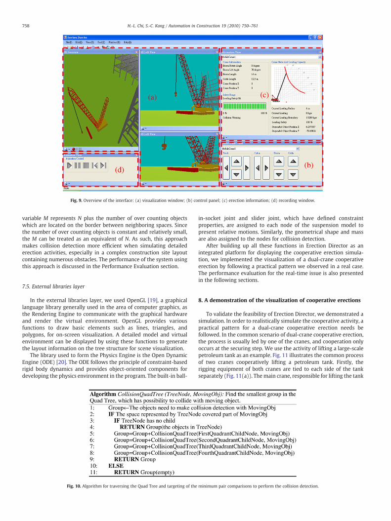
Fig. 9. Overview of the interface: (a) visualization window; (b) control panel; (c) erection information; (d) recording window.
758 H.-L. Chi, S.-C. Kang / Automation in Construction 19 (2010) 750–761
variable M represents N plus the number of over counting objectswhich are located on the border between neighboring spaces. Sincethe number of over counting objects is constant and relatively small,the M can be treated as an equivalent of N. As such, this approachmakes collision detection more efficient when simulating detailederection activities, especially in a complex construction site layoutcontaining numerous obstacles. The performance of the system usingthis approach is discussed in the Performance Evaluation section.
7.5. External libraries layer
In the external libraries layer, we used OpenGL [19], a graphicallanguage library generally used in the area of computer graphics, asthe Rendering Engine to communicate with the graphical hardwareand render the virtual environment. OpenGL provides variousfunctions to draw basic elements such as lines, triangles, andpolygons, for on-screen visualization. A detailed model and virtualenvironment can be displayed by using these functions to generatethe layout information on the tree structure for scene visualization.
The library used to form the Physics Engine is the Open DynamicEngine (ODE) [20]. The ODE follows the principle of constraint-basedrigid body dynamics and provides object-oriented components fordeveloping the physics environment in the program. The built-in ball-
Fig. 10. Algorithm for traversing the Quad Tree and targeting of the
in-socket joint and slider joint, which have defined constraintproperties, are assigned to each node of the suspension model topresent relative motions. Similarly, the geometrical shape and massare also assigned to the nodes for collision detection.
After building up all these functions in Erection Director as anintegrated platform for displaying the cooperative erection simula-tion, we implemented the visualization of a dual-crane cooperativeerection by following a practical pattern we observed in a real case.The performance evaluation for the real-time issue is also presentedin the following sections.
8. A demonstration of the visualization of cooperative erections
To validate the feasibility of Erection Director, we demonstrated asimulation. In order to realistically simulate the cooperative activity, apractical pattern for a dual-crane cooperative erection needs befollowed. In the common scenario of dual-crane cooperative erection,the process is usually led by one of the cranes, and cooperation onlyoccurs at the securing step. We use the activity of lifting a large-scalepetroleum tank as an example. Fig. 11 illustrates the common processof two cranes cooperatively lifting a petroleum tank. Firstly, therigging equipment of both cranes are tied to each side of the tankseparately (Fig. 11(a)). The main crane, responsible for lifting the tank
minimum pair comparisons to perform the collision detection.
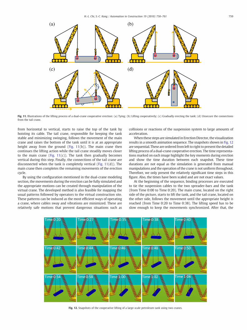
Fig. 11. Illustrations of the lifting process of a dual-crane cooperative erection: (a) Tying; (b) Lifting cooperatively; (c) Gradually erecting the tank; (d) Unsecure the connectionsfrom the tail crane.
759H.-L. Chi, S.-C. Kang / Automation in Construction 19 (2010) 750–761
from horizontal to vertical, starts to raise the top of the tank byhoisting its cable. The tail crane, responsible for keeping the tankstable and minimizing swinging, follows the movement of the maincrane and raises the bottom of the tank until it is at an appropriateheight away from the ground (Fig. 11(b)). The main crane thencontinues the lifting action while the tail crane steadily moves closerto the main crane (Fig. 11(c)). The tank then gradually becomesvertical during this step. Finally, the connections of the tail crane aredisconnected when the tank is completely vertical (Fig. 11(d)). Themain crane then completes the remaining movements of the erectioncycle.
By using the configuration mentioned in the dual-crane modelingsection, themovements during the erection can be fully simulated andthe appropriate motions can be created through manipulation of thevirtual crane. The developed method is also feasible for mapping theusual patterns followed by operators to the virtual construction site.These patterns can be induced as the most efficient ways of operatinga crane, where cables sway and vibrations are minimized. These arerelatively safe motions that prevent dangerous situations such as
Fig. 12. Snapshots of the cooperative lifting of a l
collisions or reactions of the suspension system to large amounts ofacceleration.
When these steps are simulated inErectionDirector, thevisualizationresults in a smooth animation sequence. The snapshots shown in Fig. 12are sequential. These are ordered from left to right topresent thedetailedliftingprocess of a dual-crane cooperative erection. The time representa-tionsmarked on each image highlight the key moments during erectionand show the time duration between each snapshot. These timedurations are not equal as the simulation is generated from manualmanipulations and the operation of the crane is not uniform throughout.Therefore, we only present the relatively significant time steps in thisfigure. Also, the times have been scaled and are not exact values.
At the beginning of the sequence, binding processes are executedto tie the suspension cables to the two spreader-bars and the tank(from Time 0:00 to Time 0:20). The main crane, located on the rightside of the picture, starts to lift the tank, and the tail crane, located onthe other side, follows the movement until the appropriate height isreached (from Time 0:20 to Time 0:38). The lifting speed has to beslow enough to keep the movements synchronized. After that, the
arge-scale petroleum tank using two cranes.
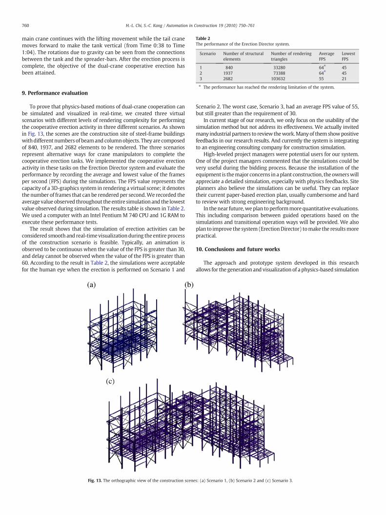
Table 2The performance of the Erection Director system.
Scenario Number of structuralelements
Number of renderingtriangles
AverageFPS
LowestFPS
1 840 33280 64⁎ 452 1937 73388 64⁎ 45
760 H.-L. Chi, S.-C. Kang / Automation in Construction 19 (2010) 750–761
main crane continues with the lifting movement while the tail cranemoves forward to make the tank vertical (from Time 0:38 to Time1:04). The rotations due to gravity can be seen from the connectionsbetween the tank and the spreader-bars. After the erection process iscomplete, the objective of the dual-crane cooperative erection hasbeen attained.
3 2682 103632 55 21
⁎ The performance has reached the rendering limitation of the system.
9. Performance evaluationTo prove that physics-based motions of dual-crane cooperation canbe simulated and visualized in real-time, we created three virtualscenarios with different levels of rendering complexity for performingthe cooperative erection activity in three different scenarios. As shownin Fig. 13, the scenes are the construction site of steel-frame buildingswithdifferent numbers of beamand columnobjects. They are composedof 840, 1937, and 2682 elements to be rendered. The three scenariosrepresent alternative ways for crane manipulators to complete thecooperative erection tasks. We implemented the cooperative erectionactivity in these tasks on the Erection Director system and evaluate theperformance by recording the average and lowest value of the framesper second (FPS) during the simulations. The FPS value represents thecapacity of a 3D-graphics system in rendering a virtual scene; it denotesthe number of frames that can be rendered per second.We recorded theaverage value observed throughout the entire simulation and the lowestvalue observed during simulation. The results table is shown in Table 2.We used a computer with an Intel Pentium M 740 CPU and 1G RAM toexecute these performance tests.
The result shows that the simulation of erection activities can beconsidered smoothand real-timevisualizationduring the entire processof the construction scenario is feasible. Typically, an animation isobserved to be continuous when the value of the FPS is greater than 30,and delay cannot be observed when the value of the FPS is greater than60. According to the result in Table 2, the simulations were acceptablefor the human eye when the erection is performed on Scenario 1 and
Fig. 13. The orthographic view of the construction scene
Scenario 2. The worst case, Scenario 3, had an average FPS value of 55,but still greater than the requirement of 30.
In current stage of our research, we only focus on the usability of thesimulation method but not address its effectiveness. We actually invitedmany industrial partners to review thework.Many of themshowpositivefeedbacks in our research results. And currently the system is integratingto an engineering consulting company for construction simulation.
High-leveled project managers were potential users for our system.One of the project managers commented that the simulations could bevery useful during the bidding process. Because the installation of theequipment is themajor concerns in aplant construction, the ownerswillappreciate a detailed simulation, especially with physics feedbacks. Siteplanners also believe the simulations can be useful. They can replacetheir current paper-based erection plan, usually cumbersome and hardto review with strong engineering background.
In the near future,weplan toperformmorequantitative evaluations.This including comparison between guided operations based on thesimulations and transitional operation ways will be provided. We alsoplan to improve the system(ErectionDirector) tomake the resultsmorepractical.
10. Conclusions and future works
The approach and prototype system developed in this researchallows for the generation and visualization of a physics-based simulation
s: (a) Scenario 1, (b) Scenario 2 and (c) Scenario 3.
761H.-L. Chi, S.-C. Kang / Automation in Construction 19 (2010) 750–761
of cooperative erection activities. The combination of the manipulationand suspension model for modeling a numerical crane model can beused to derive various construction scenarios to simulate actualsituations. The simulations in this research provide detailed informationon the motions of cooperative erection activities by following theprinciple of kinematics anddynamics. From theperformance evaluation,realistic simulations can be performed in real time. The prototypesystem, Erection Director, was developed to plan erection scenarios andprovides physical actions in an instructive way and rigging informationto assist users in evaluating feasibility and rationality before actualconstruction. It will be a clear and simple way for engineers, and non-engineers alike, to identify potentially dangerous situations due toirregular movements or collisions. Planners may then generate severalalternative plans, or modify existing plans, to produce differentsimulations. A preferred efficient solution based on the results of thesimulations can then be implemented.
In the future, the evaluations for performing the real cooperativecrane operations based on the simulation results will be promoted. Andit will be able to examine the physics-based simulation in practicalperspective. Furthermore, the boarder applications of the system couldbe extended to many purposes. For example, the simulation methodscan be used to review of erection plan. Because precise simulations areavailable, the designers can “see” the construction progress duringdesign phase. Many unsafe cranemovements can be avoided during thereview process. Another example is that the physics-based simulationcan become a good reference in a bidding process. Because all theerection details can simulated, the owners can havemore confidence toadopt the proposed solution. In addition, ourwork can also be extendedfor training purpose by designing appropriate learning lessons andintegrating them into the virtual environment. Also, it can be assisted byother equipments, such as HMD, immersive screen setups, and so on, toimprove the training performance.
Acknowledgments
This work was supported by the National Science Council ofTaiwan. We thank RUENTEX Corporation for providing the construc-tion information of the practice erection patterns.
References
[1] Hornaday, W. C., Haas, C. T. and O'Connor, J. T., Computer-aided planning for heavylifts, Journal of Construction Engineering and Management 119(3), (1993),pp. 498–515.
[2] Lin, K. L. and Haas, C. T., Multiple heavy lifts optimization, Journal of ConstructionEngineering and Management, 122(4), (1996), pp. 354–362.
[3] Kamat, V. R. and Martinez, J. C., Visualizing simulated construction operations in3D, Journal of Computing in Civil Engineering, 15(4), (2001), pp. 329–337.
[4] Kamat, V. R. and Martinez, J. C., Efficient Interference Detection in 3D Animationsof Simulated Construction Operations, Proceedings of the 2005 InternationalConference on Computing in Civil Engineering, American Society of Civil Engineers,Reston, Virginia.
[5] Sivakumar, P. L., Varghese, K. and Babu, N. R., Automated path planning ofcooperative crane lifts using heuristic search, Journal of Computing in CivilEngineering, 17(3), (2003), pp. 197–207.
[6] Ali, M. S., Babu, N. R. and Varghese, K., Collision free path planning of cooperativecrane manipulators using genetic algorithm, Journal of Computing in CivilEngineering, 19(2), (2005), pp. 182–193.
[7] Kamat, V. R. and Martinez, J. C., Dynamic 3D visualization of articulatedconstruction equipment, Journal of Computing in Civil Engineering, 19(4),(2005), pp. 356–368.
[8] Kang, S. C., Computer Planning and simulation of construction erection processesusing single or multiple cranes, Ph.D. Dissertation, Department of Civil andEnvironmental Engineering, University of Stanford, California, 2005.
[9] Bicalho, A. and Feltman, S., MAXScript and the SDK for 3D Studio MAX, Sybex.[10] Derakhshani, D., Introducing Maya 6: 3D for Beginners, Sybex.[11] K. Erleben, J. Sporring, K. Henriksen, H. Dohlmann, Physics-Based Animation,
Charles River Media, Boston, 2005.[12] Reeves, W. T., Particle Systems — a Technique for Modeling a Class of Fuzzy
Objects, ACM Transactions on Graphics (TOG), 2(2), (1983), pp. 91–108.[13] Ju, F. and Choo, Y. S., Dynamic Analysis of Tower Cranes, Journal of Engineering
Mechanics, 131(1), (2005), pp. 88–96.[14] Denavit, J. and Hartenberg, R. S., A kinematic notation for lower-pair mechanism
based on matrices, Journal of Applied Mechanics, (1955), pp. 215–221.[15] S.C. Kang, H.L. Chi, E. Miranda, Three-dimensional Simulation and Visualization of
Crane Assisted Construction Erection Processes, Journal of Computing in Civil,Engineering, 23 (6), (2009), 363–371.
[16] K.G. Murty, Linear Complementarity, Linear and Nonlinear Programming, Helderman-Verlag, 1988 This book is now available for download from http://ioe.engin.umich.edu/people/fac/books/murty/linear_complementarity_webbook.
[17] H. Goldstein, C.P. Poole, C.P.J. Poole, J.L. Safko, Classical Mechanics3 rd Edition,Prentice Hall, 2002.
[18] Finkel, R. and Bentley, J. L., Quad Trees: A data structure for retrieval on compositekeys, Acta Informatica, 4(1), (1974), pp. 1–9.
[19] Shreiner, D., Woo, M., Davis, T. and Neider, J., OpenGL Programming Guide: TheOfficial Guide to Learning OpenGL, Version 1.4, Fourth Edition, Addison-WesleyProfessional, 2003.
[20] R. Smith, Open Dynamic Engine, 2006 Retrieved May 23, 2006, from http://ode.org.