Embed Size (px)
Citation preview
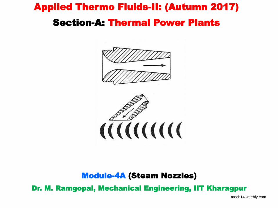
Module-4A (Steam Nozzles)
Dr. M. Ramgopal, Mechanical Engineering, IIT Kharagpur
Applied Thermo Fluids-II: (Autumn 2017)
Section-A: Thermal Power Plants
mech14.weebly.com
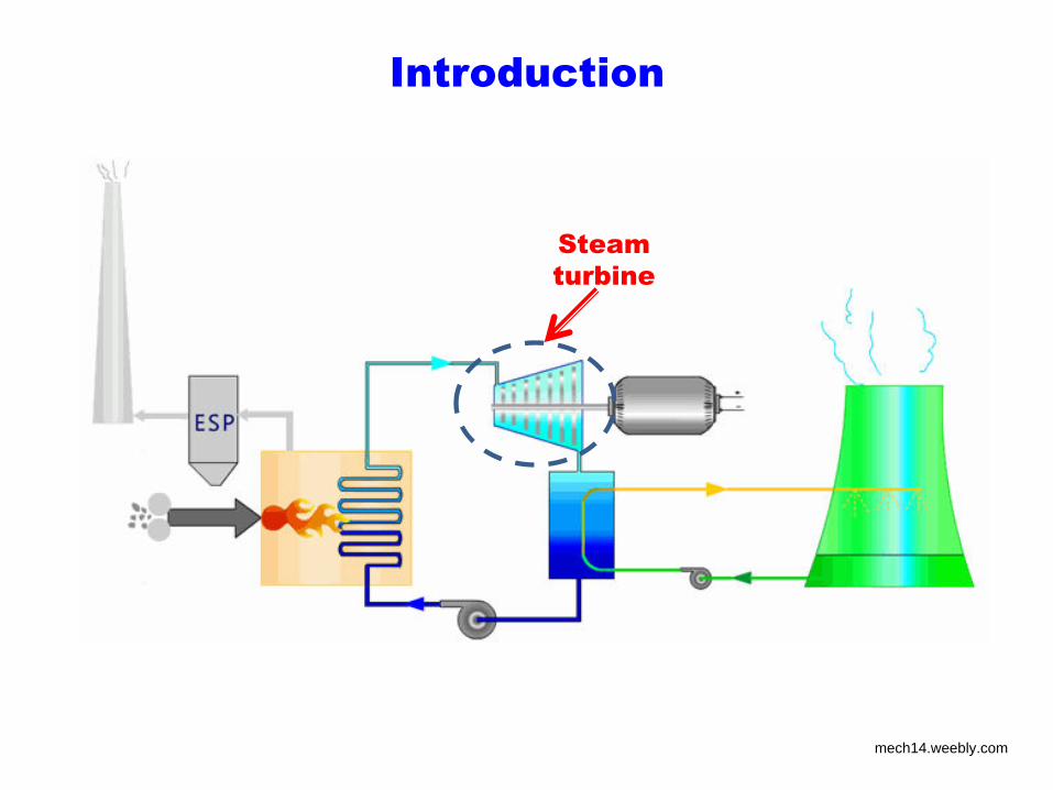
Introduction
Steam
turbine
mech14.weebly.com
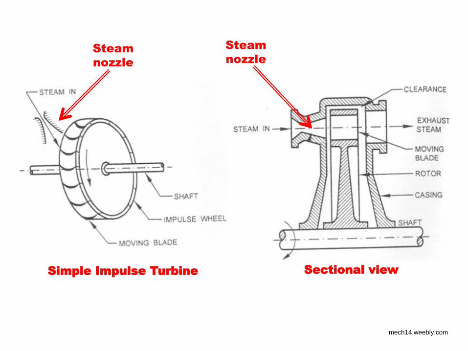
Sectional view Simple Impulse Turbine
Steam
nozzle Steam
nozzle
mech14.weebly.com
Steam nozzles
• High pressure and high temperature steam from the boiler enters
the steam turbines through a series of steam nozzles
• A nozzle is a duct of smoothly varying cross-sectional area in
which a steadily flowing fluid is made to accelerate at the expense
of pressure
• Depending upon design and operating conditions, steam nozzles
can be subsonic or supersonic
• Though steam nozzles are simple components without any
moving components, the physics underlying their operation can be
quite complex due to:
• Compressibility effects,
• Friction and Supersaturation
mech14.weebly.com
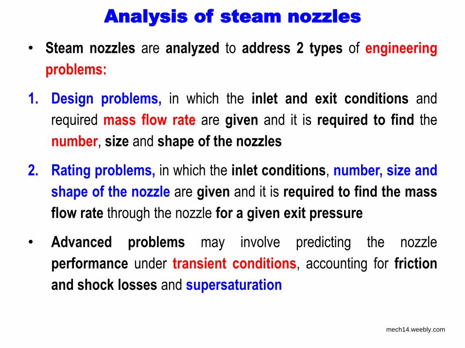
Analysis of steam nozzles
• Steam nozzles are analyzed to address 2 types of engineering
problems:
1. Design problems, in which the inlet and exit conditions and
required mass flow rate are given and it is required to find the
number, size and shape of the nozzles
2. Rating problems, in which the inlet conditions, number, size and
shape of the nozzle are given and it is required to find the mass
flow rate through the nozzle for a given exit pressure
• Advanced problems may involve predicting the nozzle
performance under transient conditions, accounting for friction
and shock losses and supersaturation
mech14.weebly.com
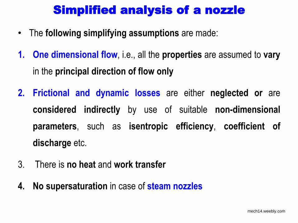
Simplified analysis of a nozzle
• The following simplifying assumptions are made:
1. One dimensional flow, i.e., all the properties are assumed to vary
in the principal direction of flow only
2. Frictional and dynamic losses are either neglected or are
considered indirectly by use of suitable non-dimensional
parameters, such as isentropic efficiency, coefficient of
discharge etc.
3. There is no heat and work transfer
4. No supersaturation in case of steam nozzles
mech14.weebly.com
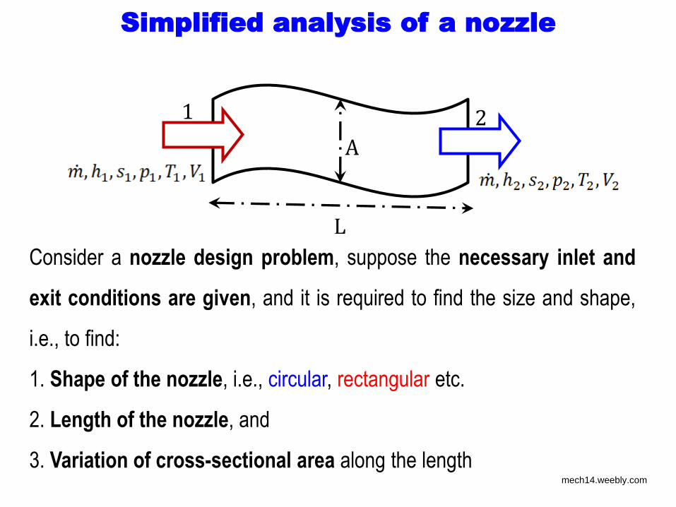
Simplified analysis of a nozzle
2 1
L
A
Consider a nozzle design problem, suppose the necessary inlet and
exit conditions are given, and it is required to find the size and shape,
i.e., to find:
1. Shape of the nozzle, i.e., circular, rectangular etc.
2. Length of the nozzle, and
3. Variation of cross-sectional area along the length mech14.weebly.com
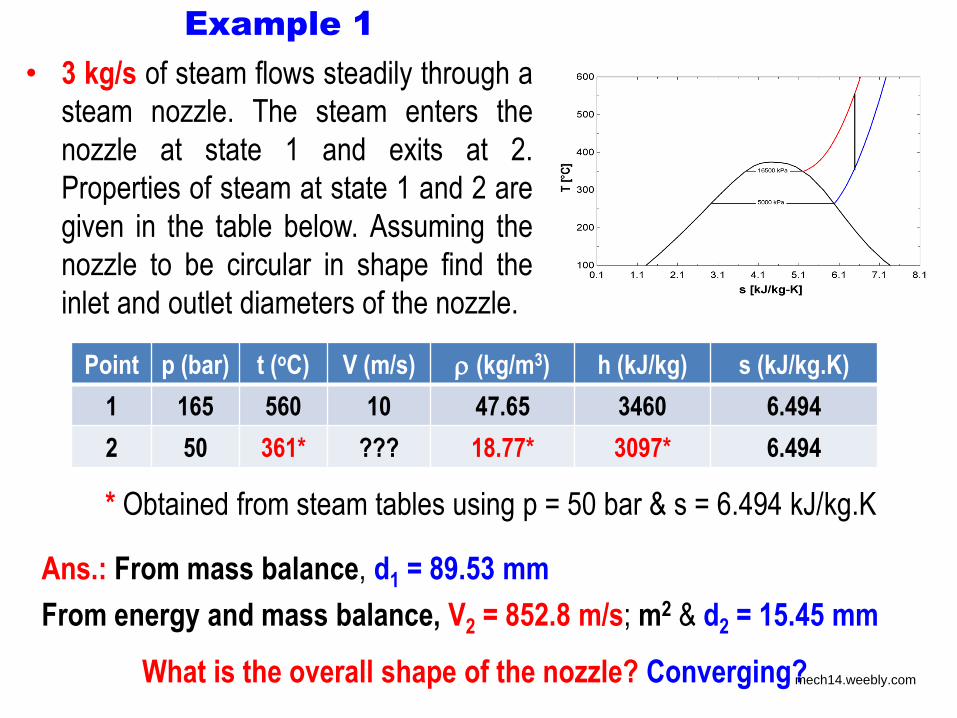
Example 1
• 3 kg/s of steam flows steadily through a
steam nozzle. The steam enters the
nozzle at state 1 and exits at 2.
Properties of steam at state 1 and 2 are
given in the table below. Assuming the
nozzle to be circular in shape find the
inlet and outlet diameters of the nozzle.
Point p (bar) t (oC) V (m/s) (kg/m3) h (kJ/kg) s (kJ/kg.K)
1 165 560 10 47.65 3460 6.494
2 50 361* ??? 18.77* 3097* 6.494
* Obtained from steam tables using p = 50 bar & s = 6.494 kJ/kg.K
Ans.: From mass balance, d1 = 89.53 mm
From energy and mass balance, V2 = 852.8 m/s; m2 & d2 = 15.45 mm
What is the overall shape of the nozzle? Converging? mech14.weebly.com
mech14.weebly.com
mech14.weebly.com
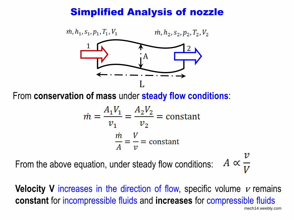
Simplified Analysis of nozzle
From conservation of mass under steady flow conditions:
2 1
L
A
From the above equation, under steady flow conditions:
Velocity V increases in the direction of flow, specific volume v remains
constant for incompressible fluids and increases for compressible fluids mech14.weebly.com
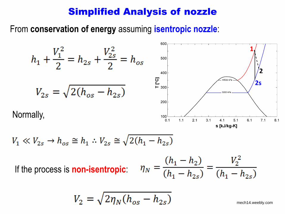
Simplified Analysis of nozzle
From conservation of energy assuming isentropic nozzle:
Normally,
If the process is non-isentropic:
2s
1
2
mech14.weebly.com
Simplified Analysis of nozzle
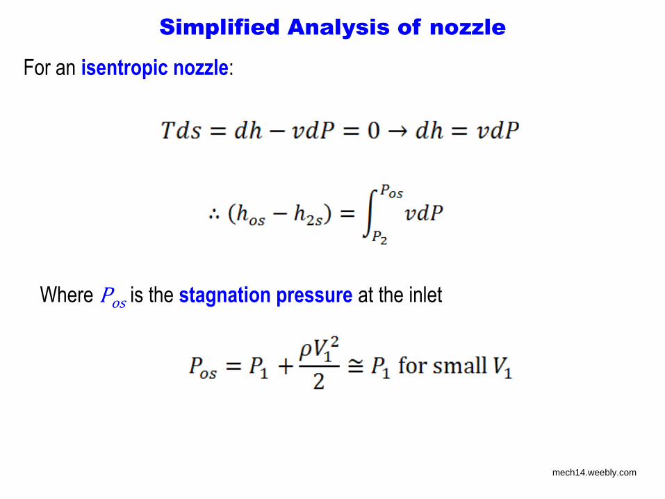
For an isentropic nozzle:
Where Pos is the stagnation pressure at the inlet
mech14.weebly.com
Simplified Analysis of nozzle
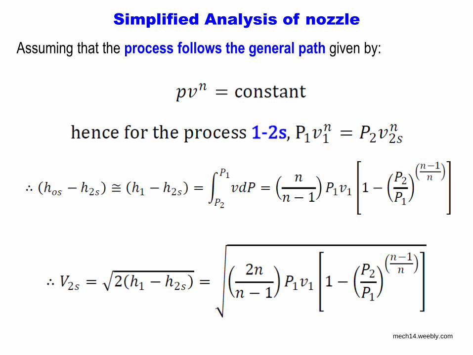
Assuming that the process follows the general path given by:
mech14.weebly.com
Simplified Analysis of nozzle
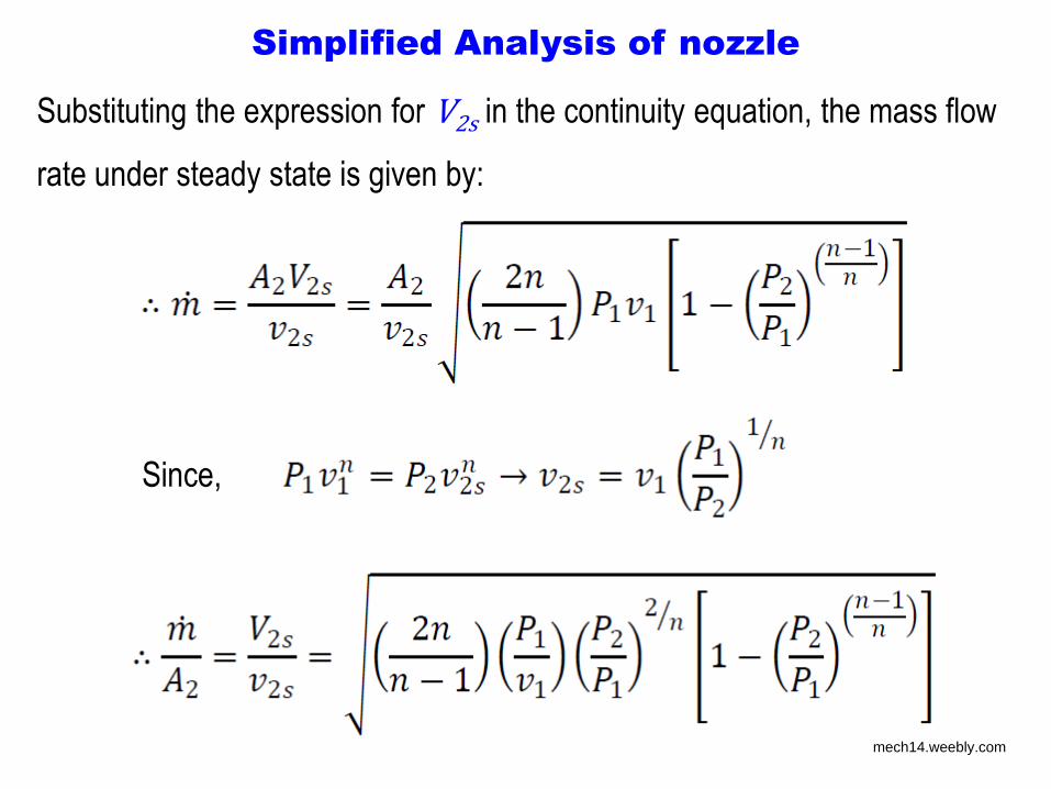
Substituting the expression for V2s in the continuity equation, the mass flow
rate under steady state is given by:
Since,
mech14.weebly.com

mech14.weebly.com
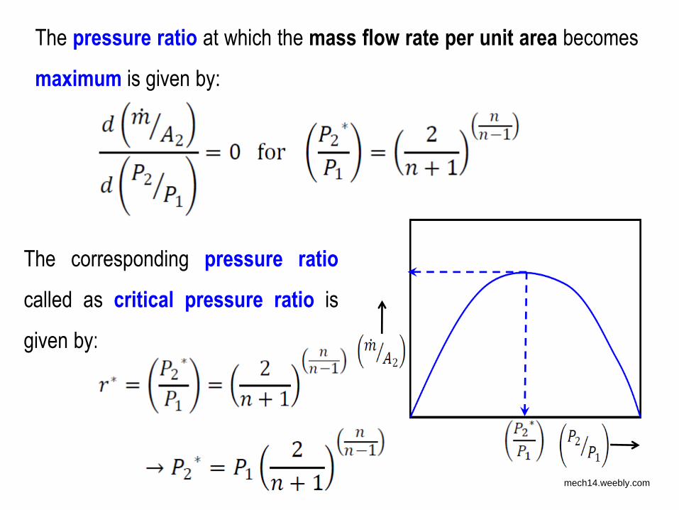
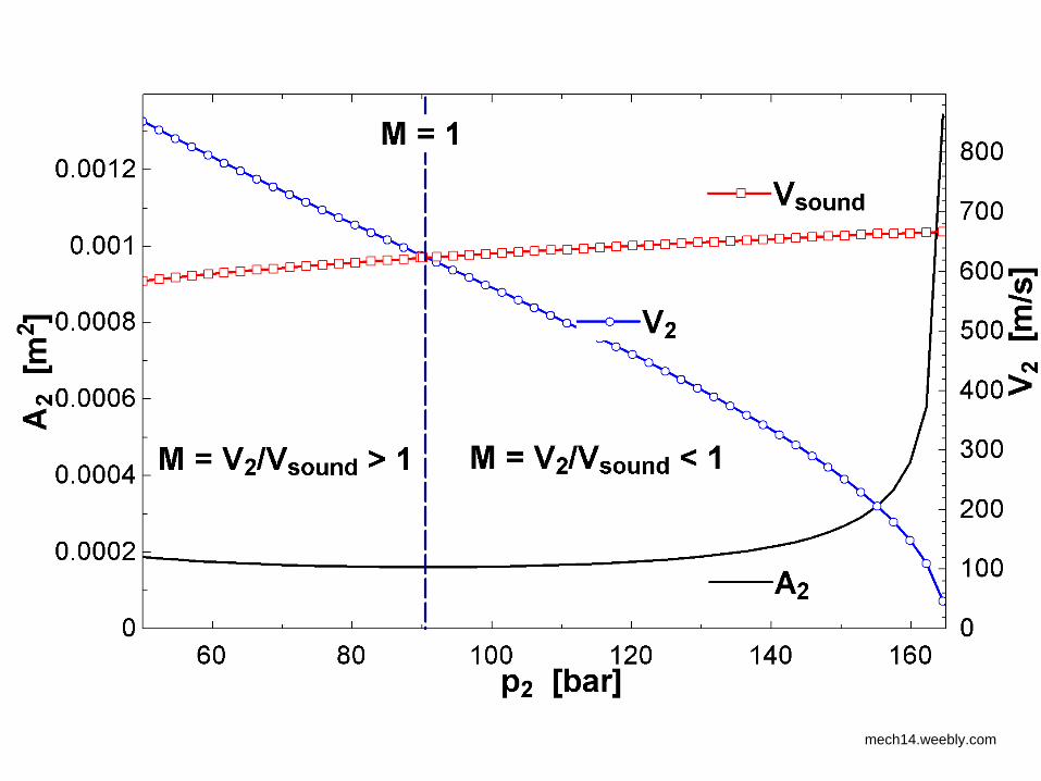
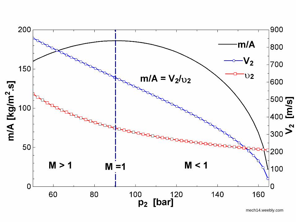
The pressure ratio at which the mass flow rate per unit area becomes
maximum is given by:
The corresponding pressure ratio
called as critical pressure ratio is
given by:
mech14.weebly.com
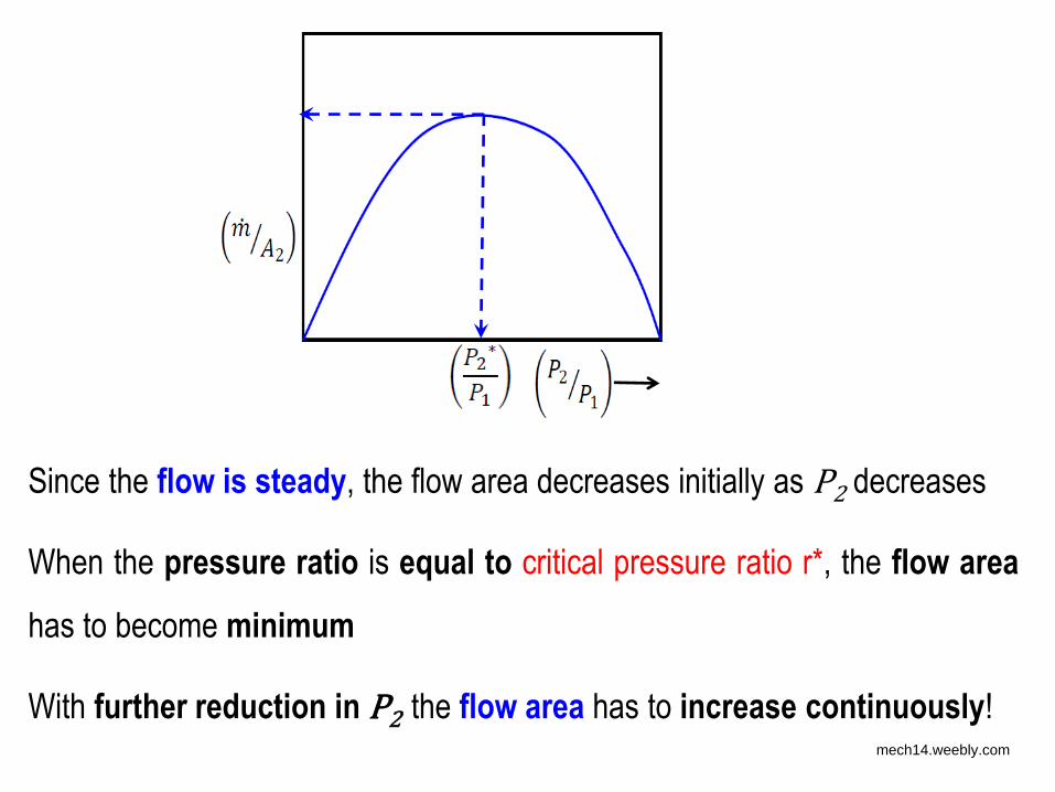
Since the flow is steady, the flow area decreases initially as P2 decreases
When the pressure ratio is equal to critical pressure ratio r*, the flow area
has to become minimum
With further reduction in P2 the flow area has to increase continuously! mech14.weebly.com
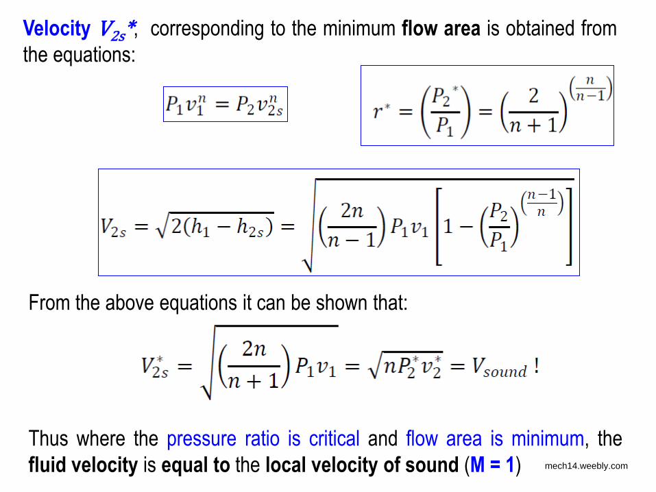
Velocity V2s*, corresponding to the minimum flow area is obtained from
the equations:
From the above equations it can be shown that:
Thus where the pressure ratio is critical and flow area is minimum, the
fluid velocity is equal to the local velocity of sound (M = 1) mech14.weebly.com

The value of coefficient n
Though the value of coefficient n changes along the process path,
approximate values of n for different fluids are given
For ideal gases, the critical temperature ratio, corresponding to critical
pressure ratio r* is given by:
mech14.weebly.com

Example 2
• Helium gas at 6.9 bar and 93oC enters a convergent nozzle with
negligible velocity and expands isentropically into a space at 3.6 bar.
Find the specific mass flow rate of helium at the exit of the nozzle.
Take the following property values for helium gas:
• cp = 5.19 kJ/kg.K, gas constant, R = 2.0785 kJ/kg.K
Ans.: 573.4 kg/m2.s
mech14.weebly.com
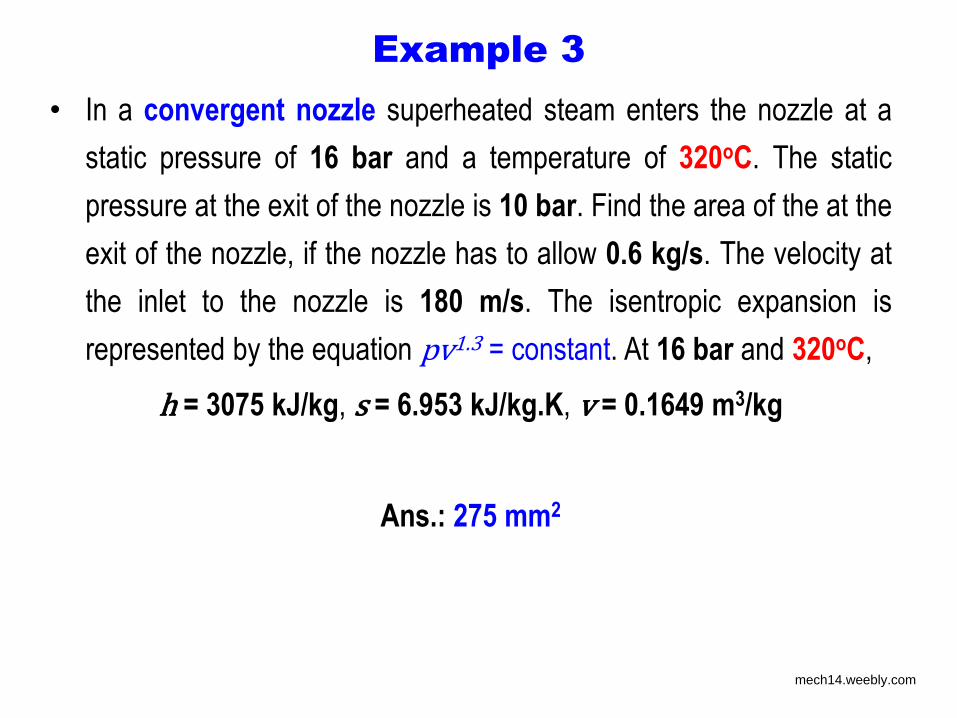
Example 3
• In a convergent nozzle superheated steam enters the nozzle at a
static pressure of 16 bar and a temperature of 320oC. The static
pressure at the exit of the nozzle is 10 bar. Find the area of the at the
exit of the nozzle, if the nozzle has to allow 0.6 kg/s. The velocity at
the inlet to the nozzle is 180 m/s. The isentropic expansion is
represented by the equation pv1.3 = constant. At 16 bar and 320oC,
h = 3075 kJ/kg, s = 6.953 kJ/kg.K, v = 0.1649 m3/kg
Ans.: 275 mm2
mech14.weebly.com
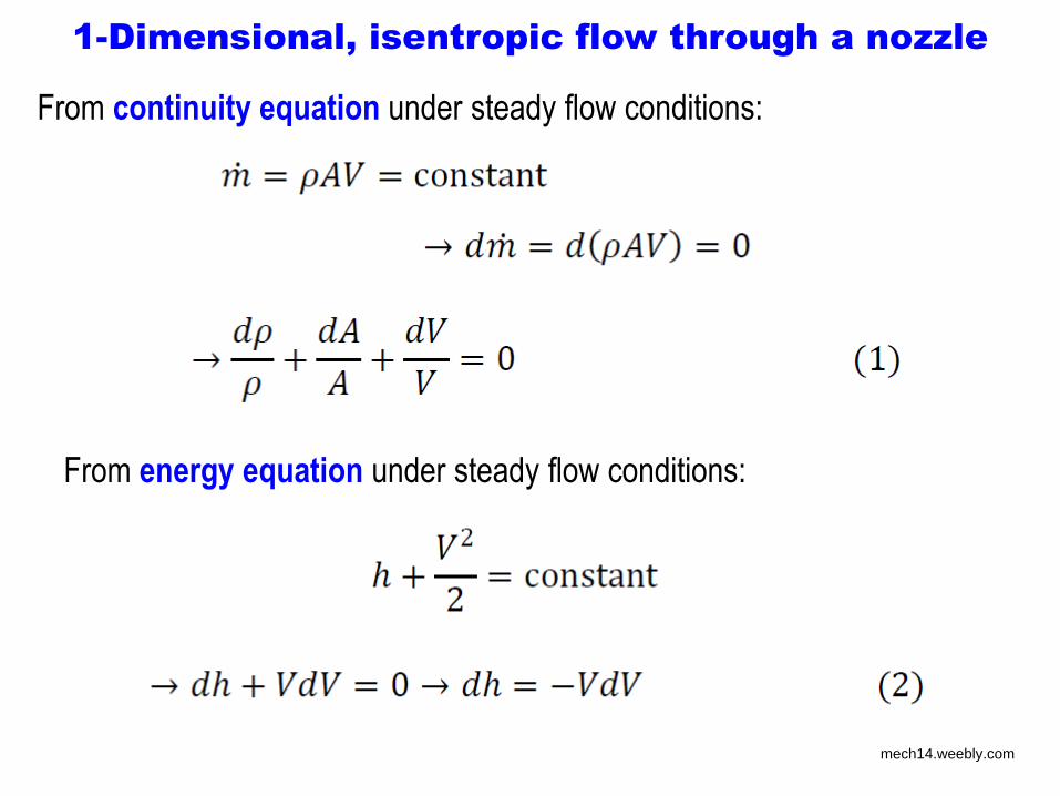
1-Dimensional, isentropic flow through a nozzle
From continuity equation under steady flow conditions:
From energy equation under steady flow conditions:
mech14.weebly.com
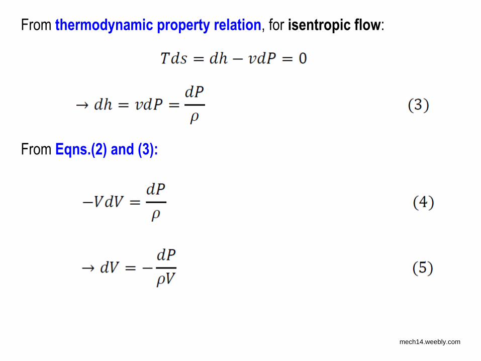
From thermodynamic property relation, for isentropic flow:
From Eqns.(2) and (3):
mech14.weebly.com
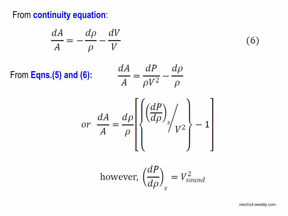
From continuity equation:
From Eqns.(5) and (6):
mech14.weebly.com
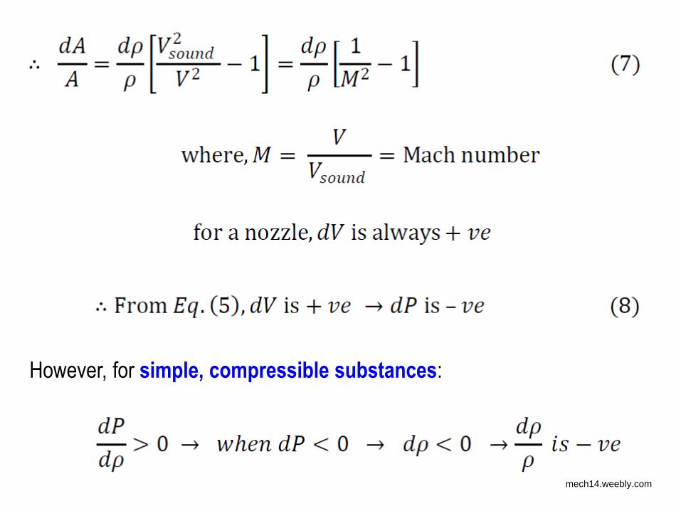
However, for simple, compressible substances:
mech14.weebly.com
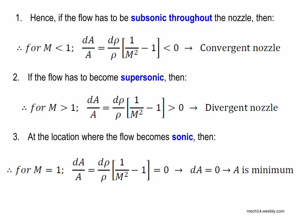
1. Hence, if the flow has to be subsonic throughout the nozzle, then:
2. If the flow has to become supersonic, then:
3. At the location where the flow becomes sonic, then:
mech14.weebly.com
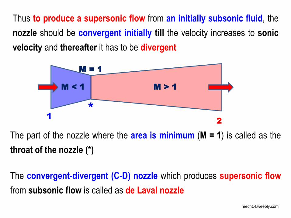
Thus to produce a supersonic flow from an initially subsonic fluid, the
nozzle should be convergent initially till the velocity increases to sonic
velocity and thereafter it has to be divergent
The part of the nozzle where the area is minimum (M = 1) is called as the
throat of the nozzle (*)
The convergent-divergent (C-D) nozzle which produces supersonic flow
from subsonic flow is called as de Laval nozzle
1 *
2
M < 1 M > 1
M = 1
mech14.weebly.com
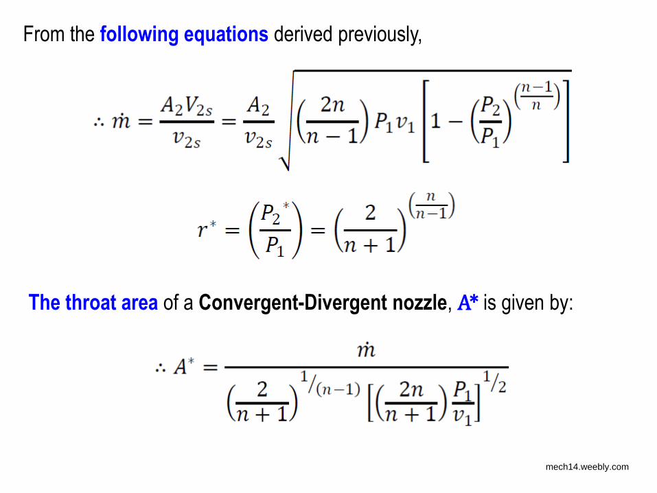
From the following equations derived previously,
The throat area of a Convergent-Divergent nozzle, A* is given by:
mech14.weebly.com
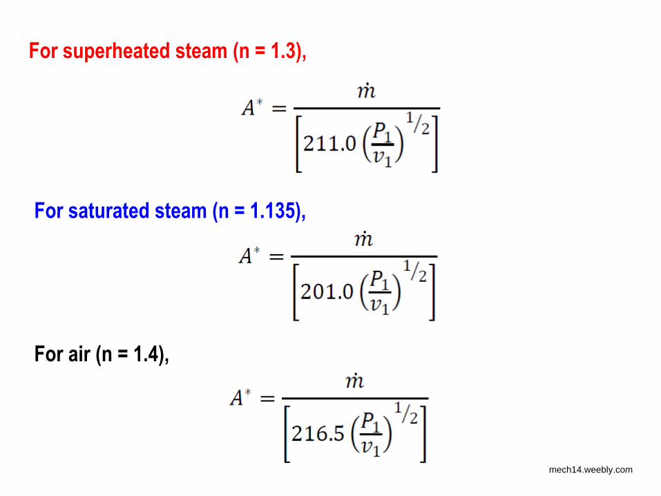
For superheated steam (n = 1.3),
For saturated steam (n = 1.135),
For air (n = 1.4),
mech14.weebly.com
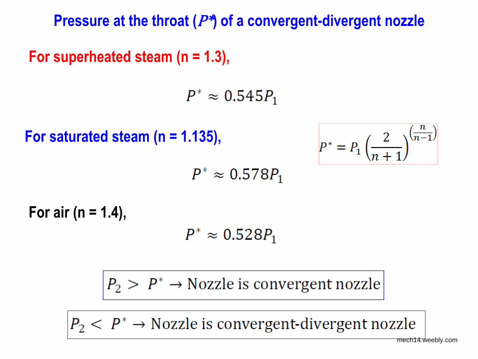
For superheated steam (n = 1.3),
For saturated steam (n = 1.135),
For air (n = 1.4),
Pressure at the throat (P*) of a convergent-divergent nozzle
mech14.weebly.com

Example 4
• A nozzle supplying steam to an impulse turbine receives steam at 11
bar superheated by 100 K. The pressure at the exit of the nozzle is
0.15 bar. A) Find the mass flow rate through the nozzle (in kg/h) if
the area at the exit of the nozzle is 9.7 cm2. Assume isentropic
nozzle. The velocity of steam at nozzle inlet is negligible. Use the
following saturated property data and constant cp of superheated
steam of 2.3 kJ/kg.K. B) What is the shape of the nozzle?
p (bar) t (oC) x v (/m3kg) h (kJ/kg) s (kJ/kg.K)
11 184.1 1 NA 2781.7 6.5536
0.15 54 0 NA 225.9 0.7549
0.15 54 1 10.022 2599.1 8.0085
Ans.: A) 491.6 kg/h, B) Convergent-Divergent mech14.weebly.com
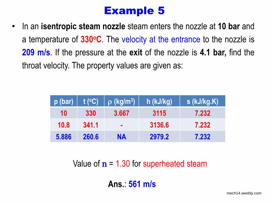
Example 5
• In an isentropic steam nozzle steam enters the nozzle at 10 bar and
a temperature of 330oC. The velocity at the entrance to the nozzle is
209 m/s. If the pressure at the exit of the nozzle is 4.1 bar, find the
throat velocity. The property values are given as:
p (bar) t (oC) (kg/m3) h (kJ/kg) s (kJ/kg.K)
10 330 3.667 3115 7.232
10.8 341.1 - 3136.6 7.232
5.886 260.6 NA 2979.2 7.232
Ans.: 561 m/s
Value of n = 1.30 for superheated steam
mech14.weebly.com
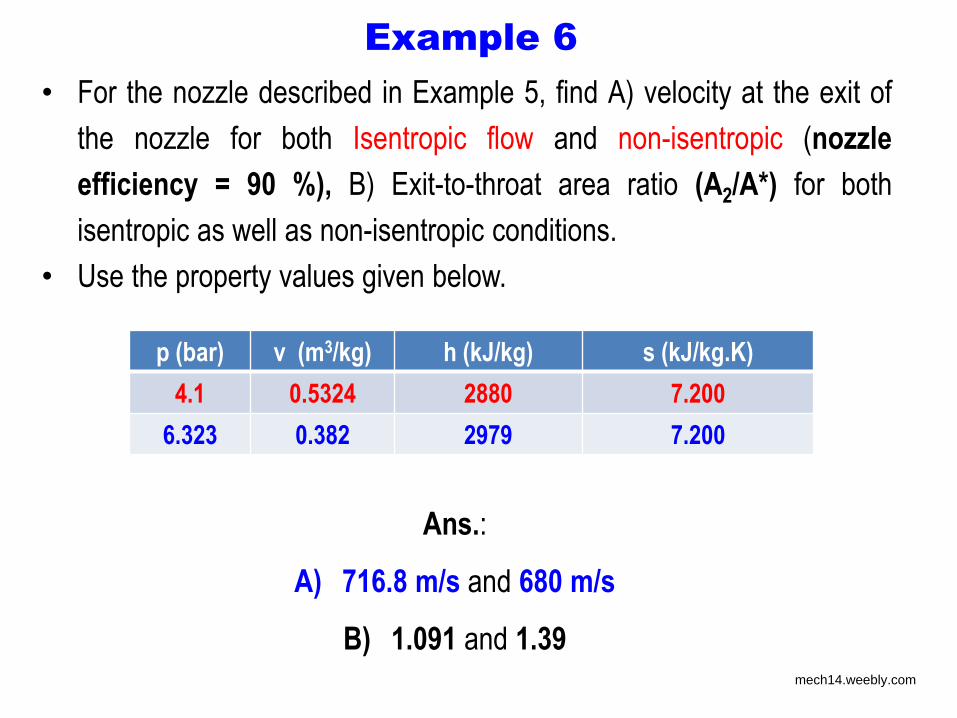
Example 6
• For the nozzle described in Example 5, find A) velocity at the exit of
the nozzle for both Isentropic flow and non-isentropic (nozzle
efficiency = 90 %), B) Exit-to-throat area ratio (A2/A*) for both
isentropic as well as non-isentropic conditions.
• Use the property values given below.
p (bar) v (m3/kg) h (kJ/kg) s (kJ/kg.K)
4.1 0.5324 2880 7.200
6.323 0.382 2979 7.200
Ans.:
A) 716.8 m/s and 680 m/s
B) 1.091 and 1.39 mech14.weebly.com
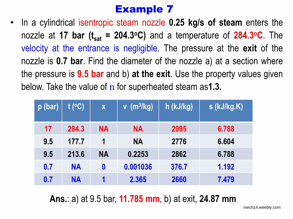
Example 7
Ans.: a) at 9.5 bar, 11.785 mm, b) at exit, 24.87 mm
• In a cylindrical isentropic steam nozzle 0.25 kg/s of steam enters the
nozzle at 17 bar (tsat = 204.3oC) and a temperature of 284.3oC. The
velocity at the entrance is negligible. The pressure at the exit of the
nozzle is 0.7 bar. Find the diameter of the nozzle a) at a section where
the pressure is 9.5 bar and b) at the exit. Use the property values given
below. Take the value of n for superheated steam as1.3.
p (bar) t (oC) x v (m3/kg)
h (kJ/kg) s (kJ/kg.K)
17 284.3 NA NA 2995 6.788
9.5 177.7 1 NA 2776 6.604
9.5 213.6 NA 0.2253 2862 6.788
0.7 NA 0 0.001036 376.7 1.192
0.7 NA 1 2.365 2660 7.479
mech14.weebly.com
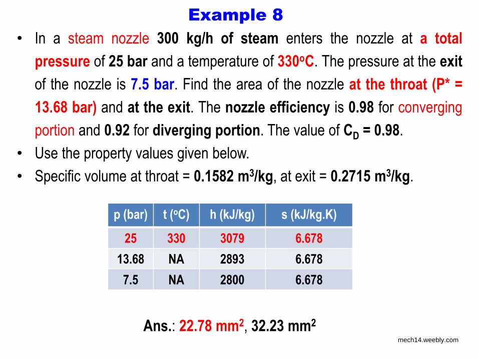
Example 8
Ans.: 22.78 mm2, 32.23 mm2
• In a steam nozzle 300 kg/h of steam enters the nozzle at a total
pressure of 25 bar and a temperature of 330oC. The pressure at the exit
of the nozzle is 7.5 bar. Find the area of the nozzle at the throat (P* =
13.68 bar) and at the exit. The nozzle efficiency is 0.98 for converging
portion and 0.92 for diverging portion. The value of CD = 0.98.
• Use the property values given below.
• Specific volume at throat = 0.1582 m3/kg, at exit = 0.2715 m3/kg.
p (bar) t (oC) h (kJ/kg) s (kJ/kg.K)
25 330 3079 6.678
13.68 NA 2893 6.678
7.5 NA 2800 6.678
mech14.weebly.com
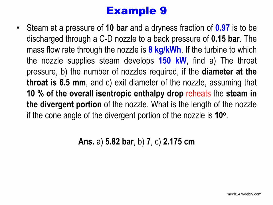
Example 9
• Steam at a pressure of 10 bar and a dryness fraction of 0.97 is to be
discharged through a C-D nozzle to a back pressure of 0.15 bar. The
mass flow rate through the nozzle is 8 kg/kWh. If the turbine to which
the nozzle supplies steam develops 150 kW, find a) The throat
pressure, b) the number of nozzles required, if the diameter at the
throat is 6.5 mm, and c) exit diameter of the nozzle, assuming that
10 % of the overall isentropic enthalpy drop reheats the steam in
the divergent portion of the nozzle. What is the length of the nozzle
if the cone angle of the divergent portion of the nozzle is 10o.
Ans. a) 5.82 bar, b) 7, c) 2.175 cm
mech14.weebly.com
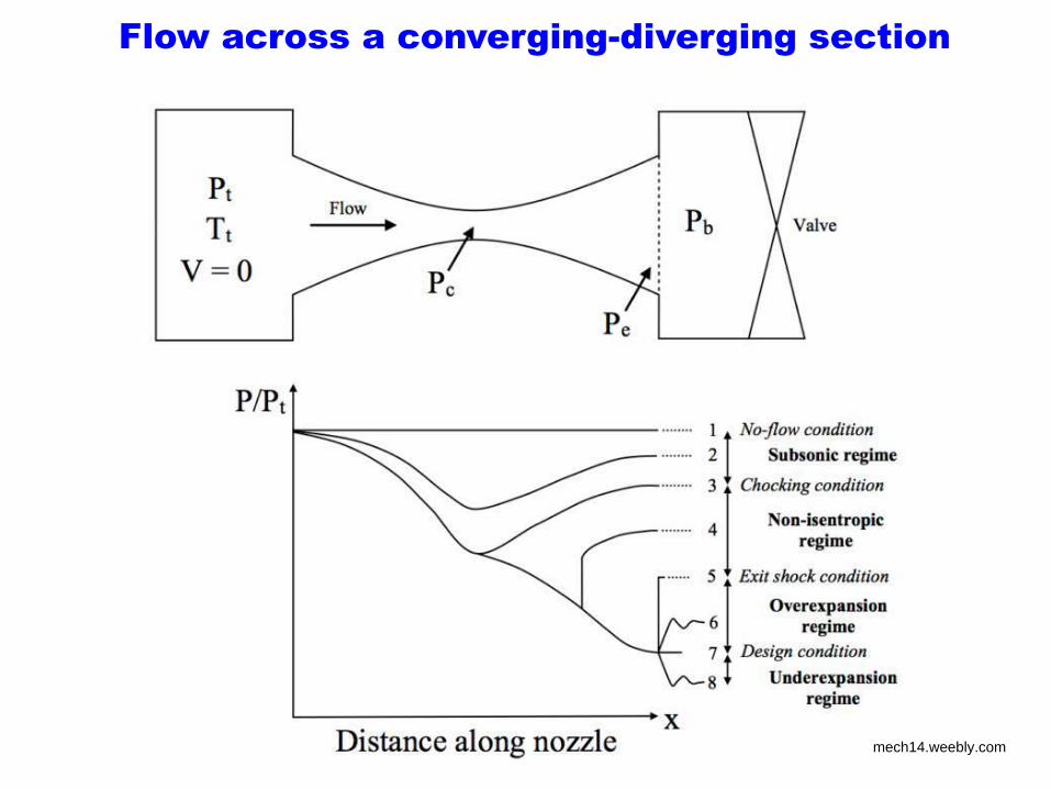
Flow across a converging-diverging section
mech14.weebly.com

Power Plant Prime movers
Applied Thermo Fluids-II (Autumn 2017): Module-4B (Prime movers)
Dr. M. Ramgopal, Mechanical Engineering, IIT Kharagpur
http://steamofboiler.blogspot.in/2011/10/steam-power-plant.html
mech14.weebly.com
Prime movers for power plants • A prime mover is that which is the cause of all movement (Aristotle)
• The component of a power plant that transforms the thermal
energy of the working fluid into mechanical energy
• The mechanical energy generated should be able to rotate a shaft
connected to the electrical generator or alternator
• The prime movers used in thermal power plants can be broadly
classified into:
1. Positive displacement type
1. Reciprocating piston cylinder engines
2. Rotating piston (e.g. Wankel) engines
2. Roto-dynamic type
1. Centrifugal turbines
2. Axial turbines mech14.weebly.com
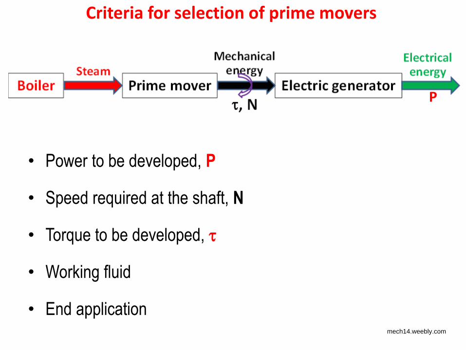
Criteria for selection of prime movers
• Power to be developed, P
• Speed required at the shaft, N
• Torque to be developed,
• Working fluid
• End application
P
mech14.weebly.com
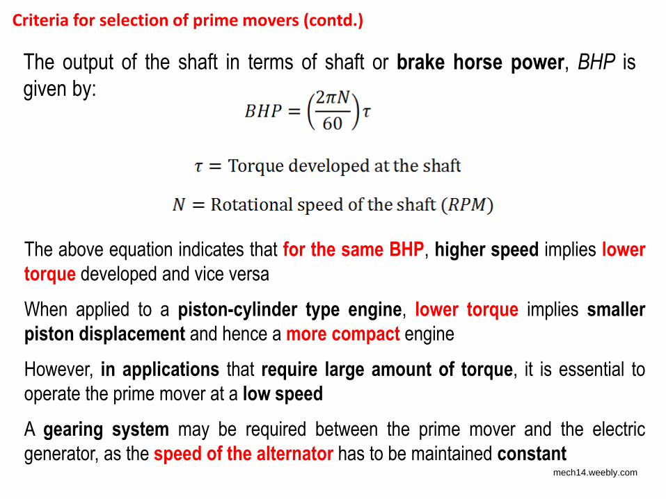
Criteria for selection of prime movers (contd.)
The above equation indicates that for the same BHP, higher speed implies lower
torque developed and vice versa
When applied to a piston-cylinder type engine, lower torque implies smaller
piston displacement and hence a more compact engine
However, in applications that require large amount of torque, it is essential to
operate the prime mover at a low speed
A gearing system may be required between the prime mover and the electric
generator, as the speed of the alternator has to be maintained constant
The output of the shaft in terms of shaft or brake horse power, BHP is
given by:
mech14.weebly.com
• The most commonly used thermal power plant
prime movers are those based on:
1. Reciprocating piston-cylinder type engines
2. Turbines
mech14.weebly.com
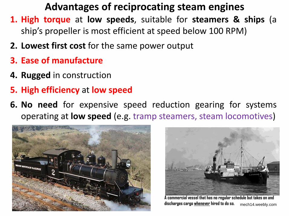
Advantages of reciprocating steam engines 1. High torque at low speeds, suitable for steamers & ships (a
ship’s propeller is most efficient at speed below 100 RPM)
2. Lowest first cost for the same power output
3. Ease of manufacture
4. Rugged in construction
5. High efficiency at low speed
6. No need for expensive speed reduction gearing for systems
operating at low speed (e.g. tramp steamers, steam locomotives)
A commercial vessel that has no regular schedule but takes on and discharges cargo whenever hired to do so. mech14.weebly.com
Limitations of reciprocating steam engines
1. Need for converting reciprocating motion into rotary
motion gives rise to:
– balancing problems, making the system very bulky
– vibration and noise
2. Need for valves and a large number of other moving
parts
3. Complex design for higher speeds
4. Lower efficiency at higher speeds
5. Large size due to need for operating the engine at lower
speed
6. The maximum power generation is limited by allowable
piston speed ( 5000 hp)
mech14.weebly.com

Introduction to turbines
• The turbine (both steam and gas) is the primary power conversion
component of thermal power plants
• In a power plant steam/gas turbine coupled to an electrical generator
– Turbine converts thermal energy into mechanical energy, and
– Electrical generator converts mechanical energy into electrical energy
• The turbines used in thermal power plants come under the general
category of “turbomachinery”
• A turbomachine is characterized by “dynamic energy exchange between
one or several rotating elements and a rapidly moving fluid”
• A turbomachine can be power generating or power absorbing, i.e.,
– Power generating – steam or gas turbine
– Power absorbing – pump or compressor mech14.weebly.com
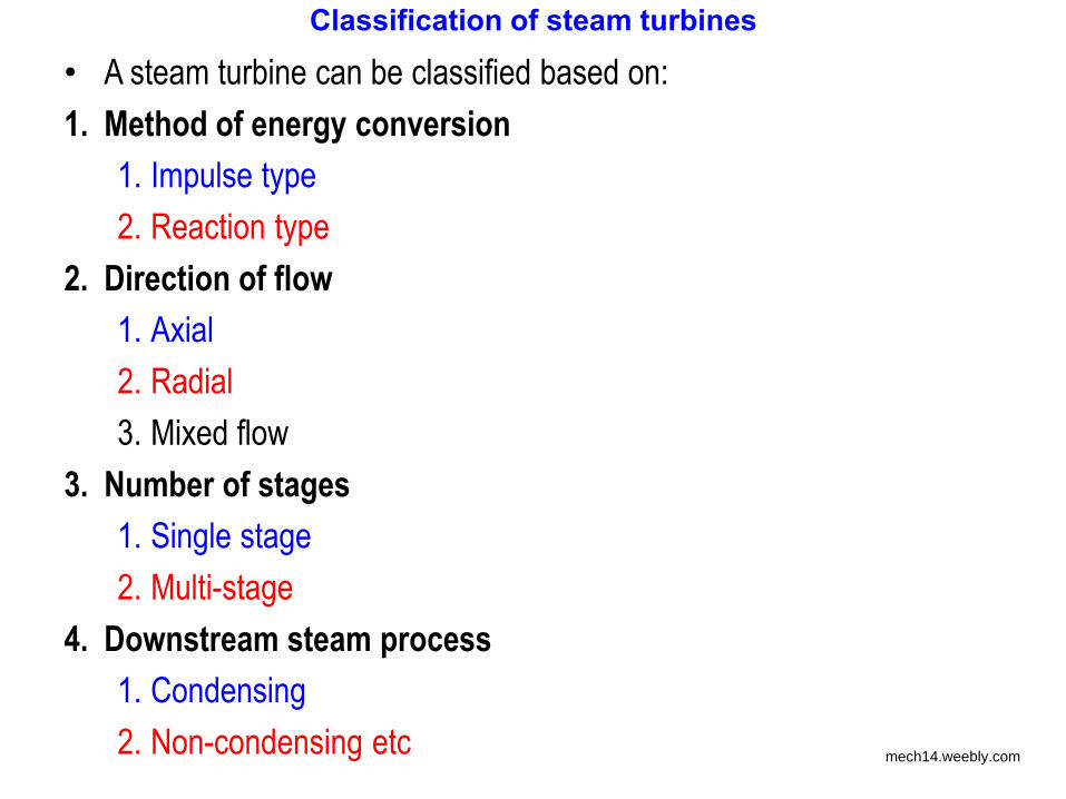
Classification of steam turbines
• A steam turbine can be classified based on:
1. Method of energy conversion
1. Impulse type
2. Reaction type
2. Direction of flow
1. Axial
2. Radial
3. Mixed flow
3. Number of stages
1. Single stage
2. Multi-stage
4. Downstream steam process
1. Condensing
2. Non-condensing etc mech14.weebly.com

Turbines vs reciprocating engines
1. Almost steady operation with no confinement or trapping of the fluid
at any point in the system – No valves!
2. High rotational speeds Very low weight-to-power ratio; 10 to 15%
of reciprocating engines
3. Minimum static and dynamic imbalance lower requirement of
vibration absorbing foundation
4. Volumetric efficiency that is almost equal to 100 %!
5. Simpler in design
6. Less noisy
7. Theoretical efficiency is marginally lower than reciprocating engine
due to high fluid friction, but actual efficiency equal to or even higher
than reciprocating engine mech14.weebly.com
Basic thermodynamics of turbines
1. In turbines, due to high fluid velocities, often close to or higher than
sonic speed, compressibility effects may play significant role
2. Due to high velocities, the changes in kinetic energy term may not
be negligible
3. Conventional method of analyzing the process by neglecting
kinetic energy term could lead to significant errors
4. Hence in the analysis of these devices, distinction has to be made
between static and stagnation properties
mech14.weebly.com
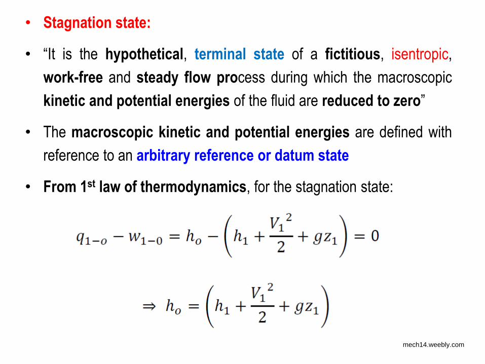
• Stagnation state:
• “It is the hypothetical, terminal state of a fictitious, isentropic,
work-free and steady flow process during which the macroscopic
kinetic and potential energies of the fluid are reduced to zero”
• The macroscopic kinetic and potential energies are defined with
reference to an arbitrary reference or datum state
• From 1st law of thermodynamics, for the stagnation state:
mech14.weebly.com
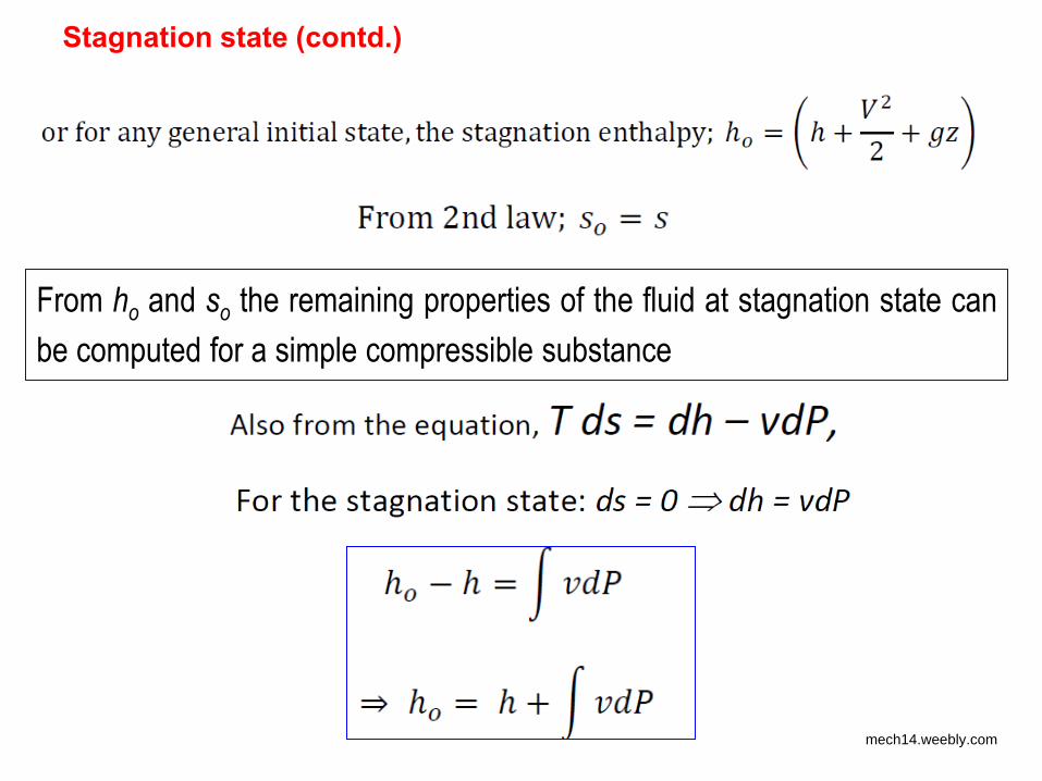
Stagnation state (contd.)
From ho and so the remaining properties of the fluid at stagnation state can
be computed for a simple compressible substance
mech14.weebly.com
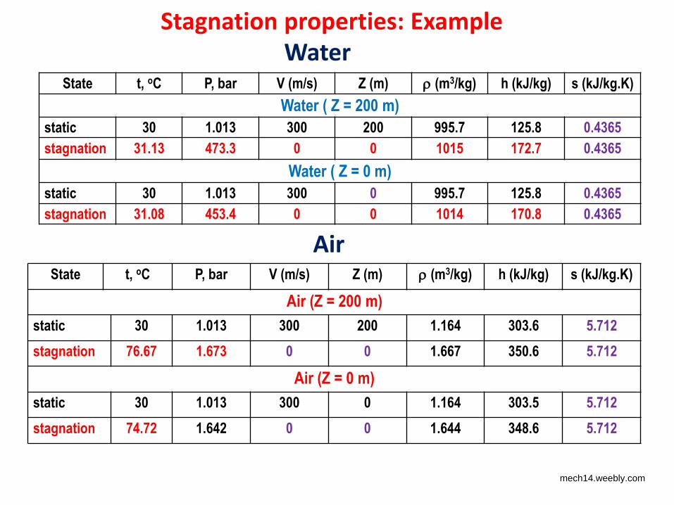
Stagnation properties: Example
State t, oC P, bar V (m/s) Z (m) (m3/kg) h (kJ/kg) s (kJ/kg.K)
Water ( Z = 200 m)
static 30 1.013 300 200 995.7 125.8 0.4365
stagnation 31.13 473.3 0 0 1015 172.7 0.4365
Water ( Z = 0 m)
static 30 1.013 300 0 995.7 125.8 0.4365
stagnation 31.08 453.4 0 0 1014 170.8 0.4365
State t, oC P, bar V (m/s) Z (m) (m3/kg) h (kJ/kg) s (kJ/kg.K)
Air (Z = 200 m)
static 30 1.013 300 200 1.164 303.6 5.712
stagnation 76.67 1.673 0 0 1.667 350.6 5.712
Air (Z = 0 m)
static 30 1.013 300 0 1.164 303.5 5.712
stagnation 74.72 1.642 0 0 1.644 348.6 5.712
Water
Air
mech14.weebly.com
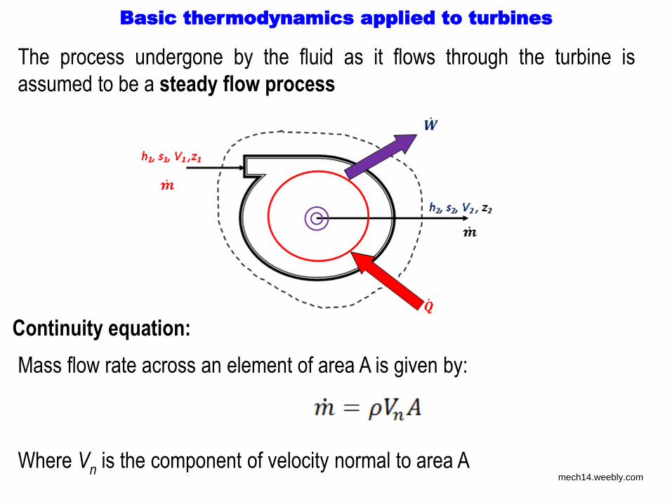
Basic thermodynamics applied to turbines
The process undergone by the fluid as it flows through the turbine is
assumed to be a steady flow process
Continuity equation:
Mass flow rate across an element of area A is given by:
Where Vn is the component of velocity normal to area A mech14.weebly.com
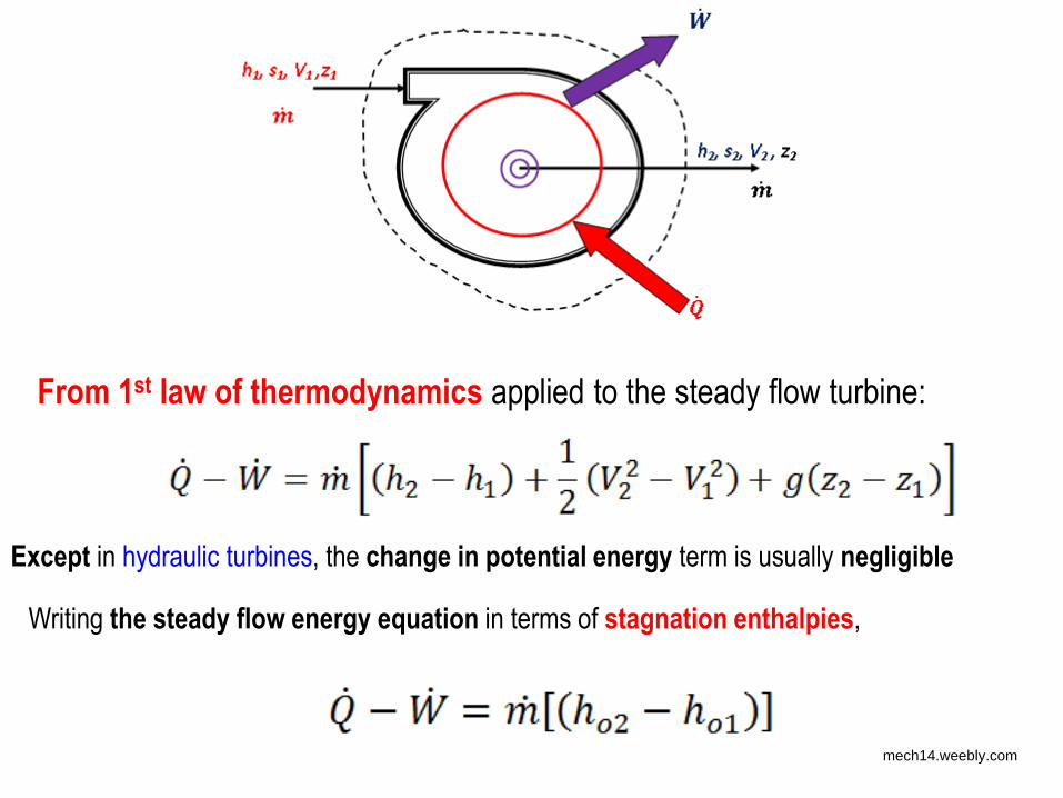
From 1st law of thermodynamics applied to the steady flow turbine:
Except in hydraulic turbines, the change in potential energy term is usually negligible
Writing the steady flow energy equation in terms of stagnation enthalpies,
mech14.weebly.com

In most of the turbo-machinery, the heat transfer term is negligible
compared to the other terms, hence:
From 2nd law of thermodynamics, for steady flow through the control
volume:
mech14.weebly.com
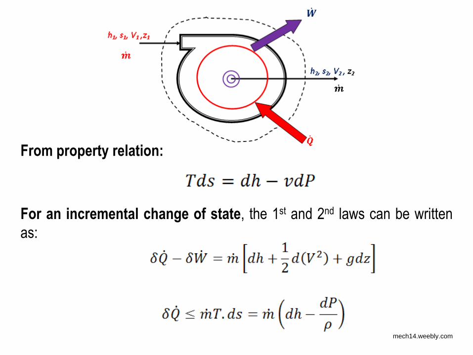
From property relation:
For an incremental change of state, the 1st and 2nd laws can be written
as:
mech14.weebly.com
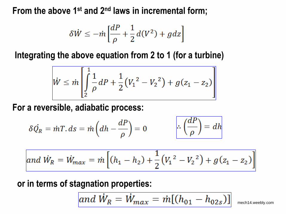
From the above 1st and 2nd laws in incremental form;
Integrating the above equation from 2 to 1 (for a turbine)
For a reversible, adiabatic process:
or in terms of stagnation properties:
mech14.weebly.com
Turbine efficiency
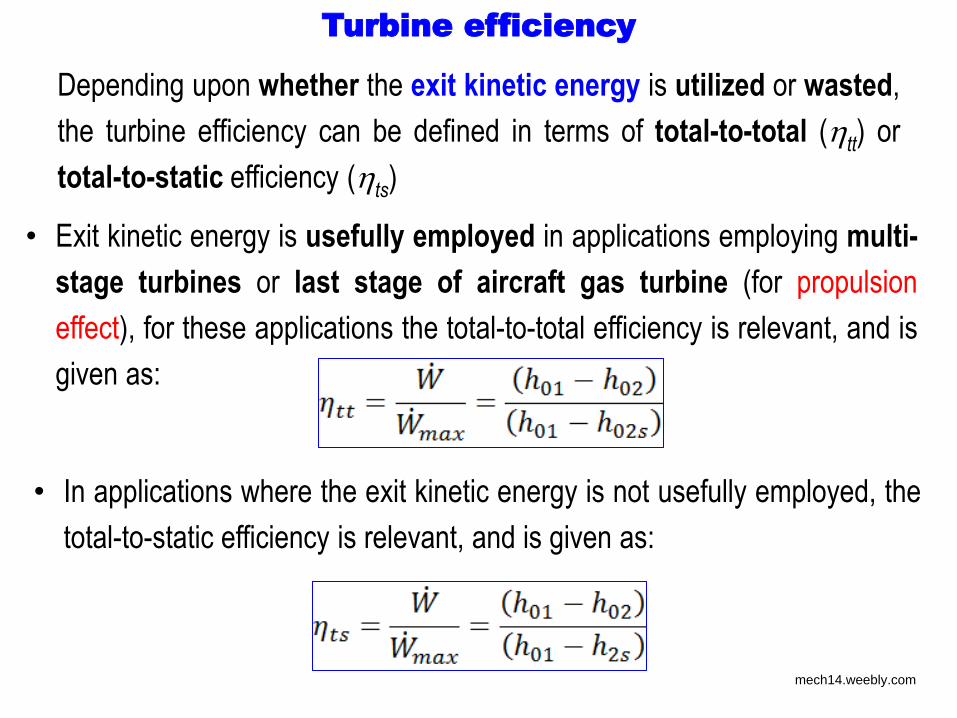
• Exit kinetic energy is usefully employed in applications employing multi-
stage turbines or last stage of aircraft gas turbine (for propulsion
effect), for these applications the total-to-total efficiency is relevant, and is
given as:
• In applications where the exit kinetic energy is not usefully employed, the
total-to-static efficiency is relevant, and is given as:
Depending upon whether the exit kinetic energy is utilized or wasted,
the turbine efficiency can be defined in terms of total-to-total (tt) or
total-to-static efficiency (ts)
mech14.weebly.com

Example problem
• In an adiabatic steam turbine, the inlet and exit conditions are as
given below:
• Inlet: 25 bar, 460oC, 700 m/s
• Exit: 0.07 bar, saturated vapour, 300 m/s
• The saturated steam properties at exit condition are:
hf = 163.4 kJ/kg, hg = 2572 kJ/kg
sf = 0.559 kJ/kg.K, sg = 8.274 kJ/kg.K
• Find the total-to-total and total-to-static efficiency of the turbine.
Ans.: 75.02 % and 72.57 %
mech14.weebly.com
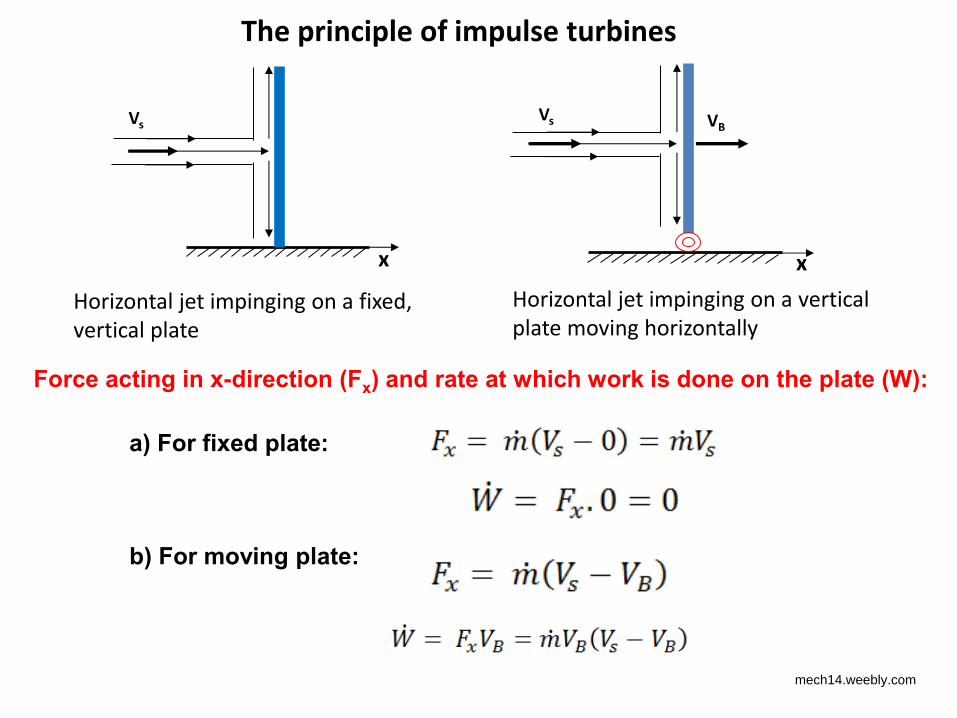
The principle of impulse turbines
Vs
Horizontal jet impinging on a fixed,
vertical plate
x
Vs VB
Horizontal jet impinging on a vertical
plate moving horizontally
x
a) For fixed plate:
Force acting in x-direction (Fx) and rate at which work is done on the plate (W):
b) For moving plate:
mech14.weebly.com
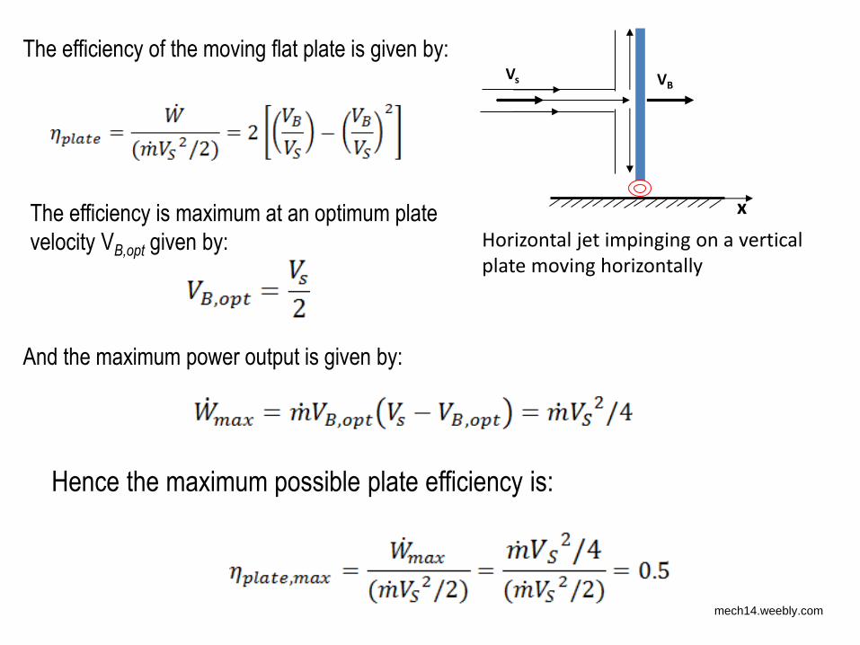
Vs VB
Horizontal jet impinging on a vertical
plate moving horizontally
x
The efficiency of the moving flat plate is given by:
The efficiency is maximum at an optimum plate
velocity VB,opt given by:
And the maximum power output is given by:
Hence the maximum possible plate efficiency is:
mech14.weebly.com
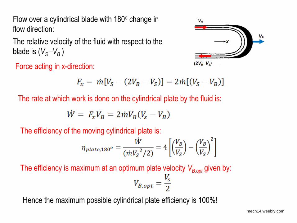
Flow over a cylindrical blade with 180o change in
flow direction:
The relative velocity of the fluid with respect to the
blade is (VSVB )
Force acting in x-direction:
The rate at which work is done on the cylindrical plate by the fluid is:
The efficiency of the moving cylindrical plate is:
The efficiency is maximum at an optimum plate velocity VB,opt given by:
Hence the maximum possible cylindrical plate efficiency is 100%! mech14.weebly.com
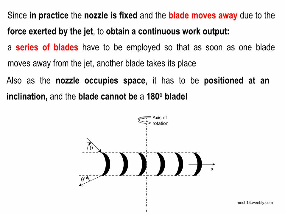
Since in practice the nozzle is fixed and the blade moves away due to the
force exerted by the jet, to obtain a continuous work output:
a series of blades have to be employed so that as soon as one blade
moves away from the jet, another blade takes its place
Also as the nozzle occupies space, it has to be positioned at an
inclination, and the blade cannot be a 180o blade!
x
Axis of
rotation
’
mech14.weebly.com
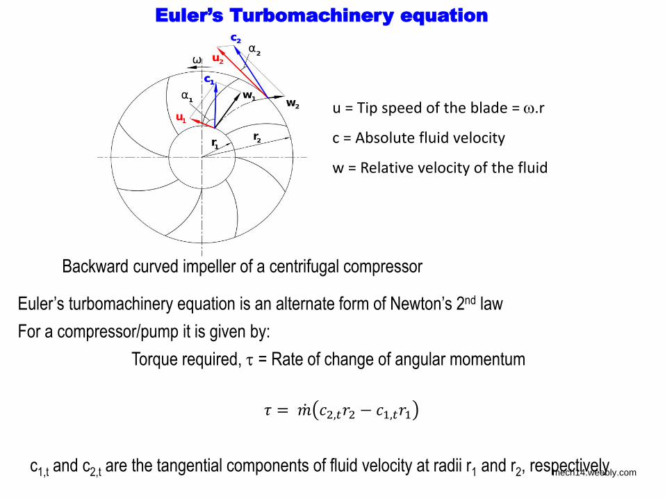
Backward curved impeller of a centrifugal compressor
u = Tip speed of the blade = .r
c = Absolute fluid velocity
w = Relative velocity of the fluid
Euler’s turbomachinery equation is an alternate form of Newton’s 2nd law
For a compressor/pump it is given by:
Torque required, = Rate of change of angular momentum
𝜏 = , − ,
c1,t and c2,t are the tangential components of fluid velocity at radii r1 and r2, respectively
Euler’s Turbomachinery equation
mech14.weebly.com
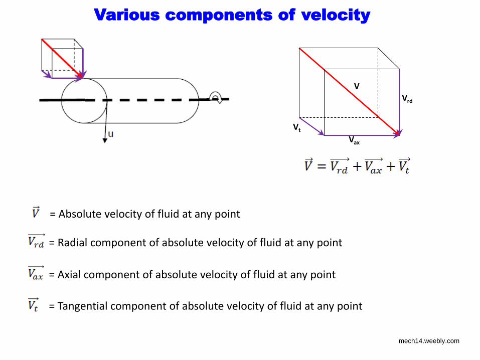
Various components of velocity
V
Vrd
Vax
Vt
= Absolute velocity of fluid at any point
= Radial component of absolute velocity of fluid at any point
= Axial component of absolute velocity of fluid at any point
= Tangential component of absolute velocity of fluid at any point
mech14.weebly.com
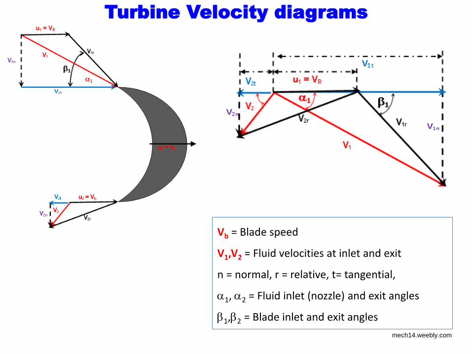
Turbine Velocity diagrams
Vb = Blade speed
V1,V2 = Fluid velocities at inlet and exit
n = normal, r = relative, t= tangential,
1, 2 = Fluid inlet (nozzle) and exit angles
1,2 = Blade inlet and exit angles
mech14.weebly.com
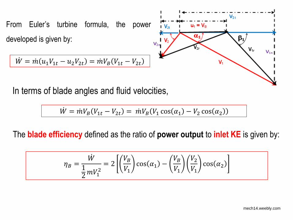
From Euler’s turbine formula, the power
developed is given by: = − = 𝐵 −
In terms of blade angles and fluid velocities, = 𝐵 − = 𝐵 cos − cos
The blade efficiency defined as the ratio of power output to inlet KE is given by:
𝜂𝐵 = = 𝐵 cos − 𝐵 cos
mech14.weebly.com
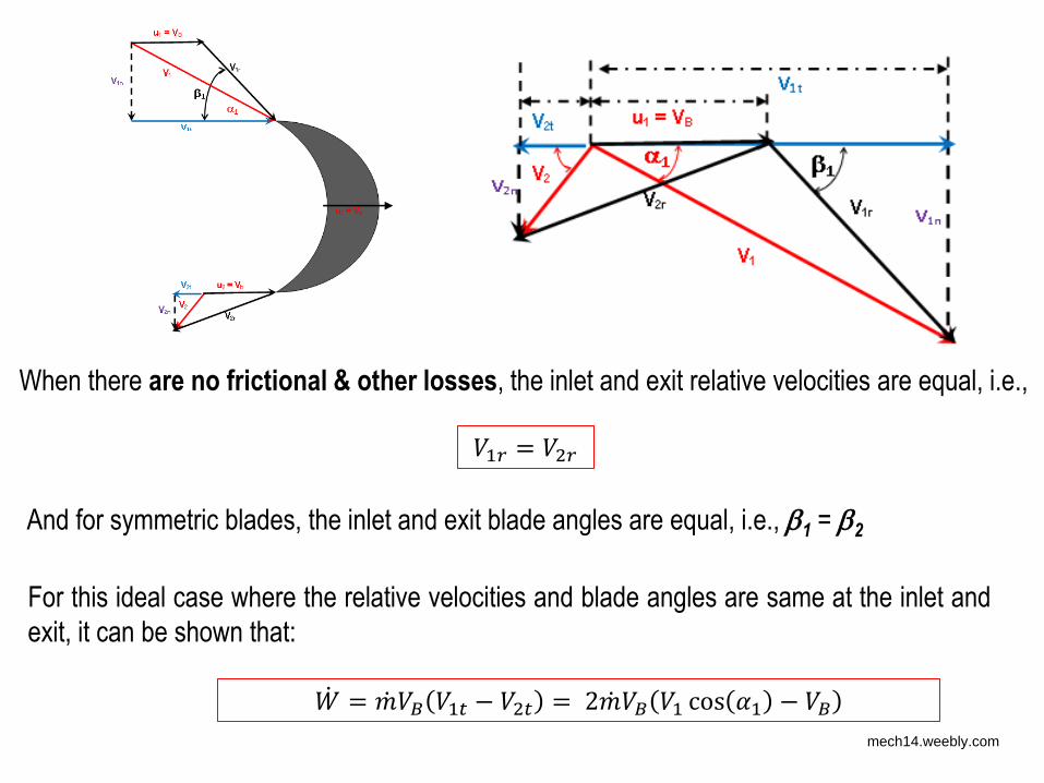
When there are no frictional & other losses, the inlet and exit relative velocities are equal, i.e., =
And for symmetric blades, the inlet and exit blade angles are equal, i.e., 1 = 2
For this ideal case where the relative velocities and blade angles are same at the inlet and
exit, it can be shown that: = 𝐵 − = 𝐵 cos − 𝐵
mech14.weebly.com
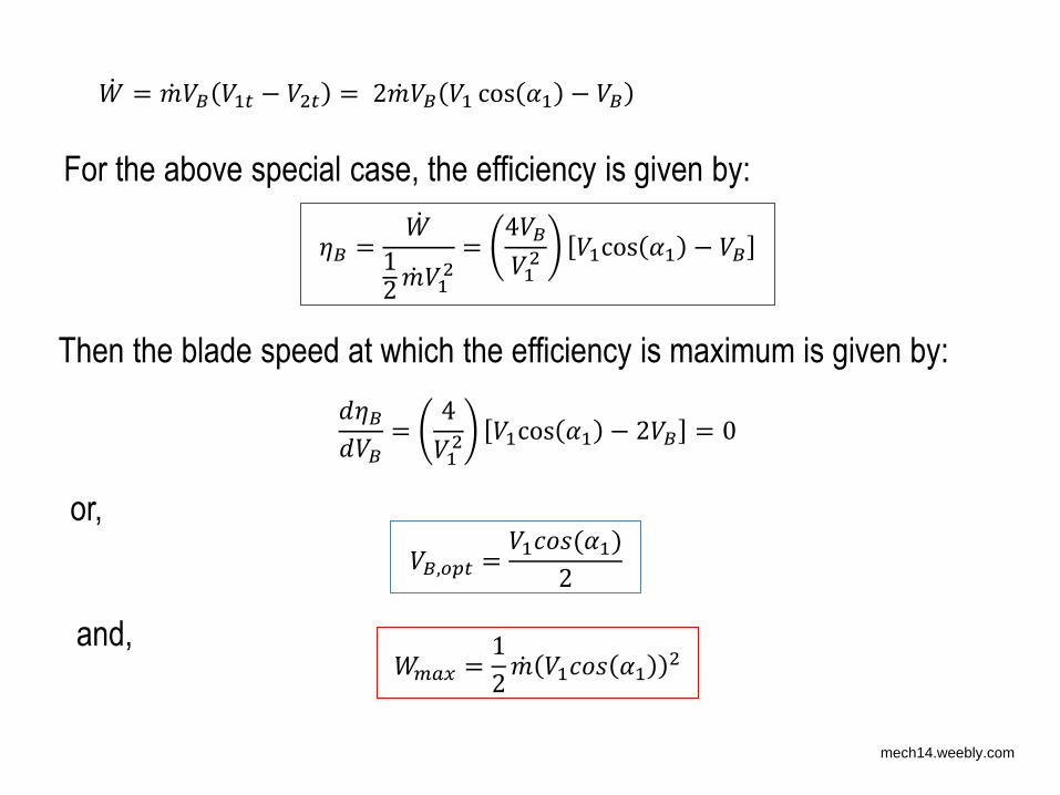
= 𝐵 − = 𝐵 cos − 𝐵
For the above special case, the efficiency is given by:
𝜂𝐵 = = 4 𝐵 cos − 𝐵
Then the blade speed at which the efficiency is maximum is given by: 𝜂𝐵𝐵 = 4 cos − 𝐵 =
𝑎𝑥 =
𝐵, =
or,
and,
mech14.weebly.com
𝑎𝑥 =
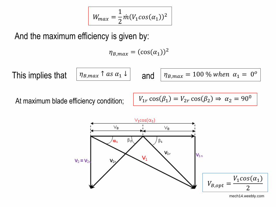
And the maximum efficiency is given by:
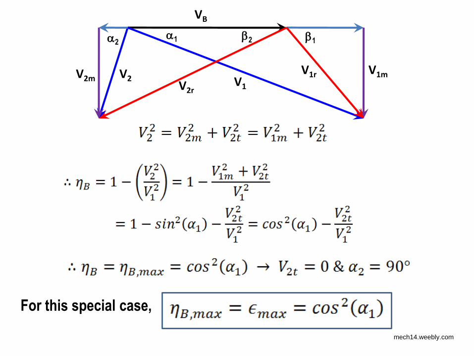
This implies that 𝜂𝐵, 𝑎𝑥 ↑ 𝑎 ↓ 𝜂𝐵, 𝑎𝑥 = % ℎ = and
At maximum blade efficiency condition; cos = cos ⇒ = 9
𝜂𝐵, 𝑎𝑥 = cos
𝐵, =
mech14.weebly.com
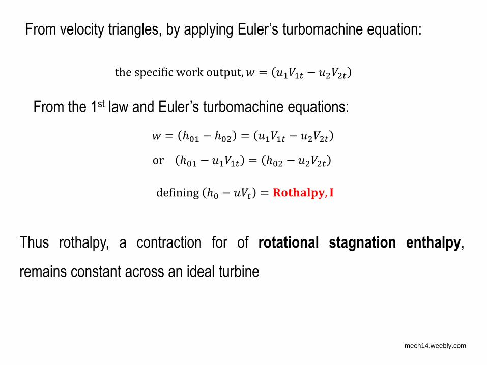
From velocity triangles, by applying Euler’s turbomachine equation:
the specific work output, = −
From the 1st law and Euler’s turbomachine equations: = ℎ − ℎ = − or ℎ − = ℎ −
Thus rothalpy, a contraction for of rotational stagnation enthalpy,
remains constant across an ideal turbine
defining ℎ − = 𝐑 𝐭𝐡𝐚𝐥 𝐲, 𝐈
mech14.weebly.com
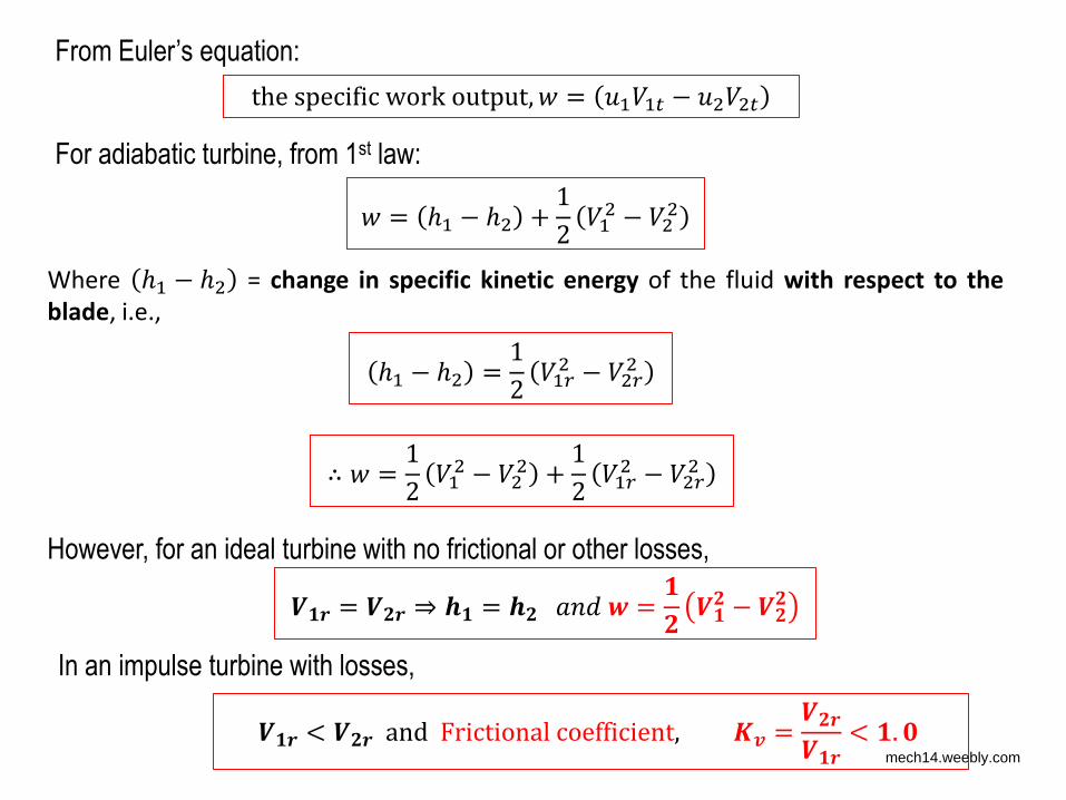
= ℎ − ℎ + −
the specific work output, = −
For adiabatic turbine, from 1st law:
From Euler’s equation:
Where ℎ − ℎ = change in specific kinetic energy of the fluid with respect to the
blade, i.e., ℎ − ℎ = −
∴ = − + −
However, for an ideal turbine with no frictional or other losses, 𝑽 𝒓 = 𝑽 𝒓 ⇒ 𝒉 = 𝒉 𝑎 = 𝑽 − 𝑽
In an impulse turbine with losses, 𝑽 𝒓 < 𝑽 𝒓 and Frictional coefficient, 𝑲 = 𝑽 𝒓𝑽 𝒓 < . mech14.weebly.com
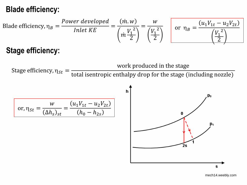
Blade efficiency:
Stage efficiency:
Blade efficiency,𝐵 = 𝑃 𝐾 = . = or 𝐵 = −
Stage efficiency,𝑆 = work produced in the stagetotal isentropic enthalpy drop for the stage including nozzle or,𝑆 = ∆ℎ = −ℎ − ℎ
mech14.weebly.com
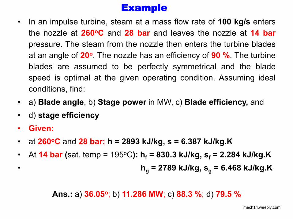
Example
• In an impulse turbine, steam at a mass flow rate of 100 kg/s enters
the nozzle at 260oC and 28 bar and leaves the nozzle at 14 bar
pressure. The steam from the nozzle then enters the turbine blades
at an angle of 20o. The nozzle has an efficiency of 90 %. The turbine
blades are assumed to be perfectly symmetrical and the blade
speed is optimal at the given operating condition. Assuming ideal
conditions, find:
• a) Blade angle, b) Stage power in MW, c) Blade efficiency, and
• d) stage efficiency
• Given:
• at 260oC and 28 bar: h = 2893 kJ/kg, s = 6.387 kJ/kg.K
• At 14 bar (sat. temp = 195oC): hf = 830.3 kJ/kg, sf = 2.284 kJ/kg.K
• hg = 2789 kJ/kg, sg = 6.468 kJ/kg.K
Ans.: a) 36.05o; b) 11.286 MW; c) 88.3 %; d) 79.5 %
mech14.weebly.com
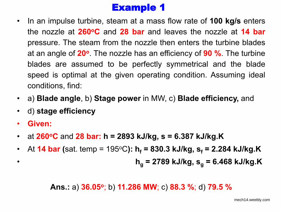
Example 1
• In an impulse turbine, steam at a mass flow rate of 100 kg/s enters
the nozzle at 260oC and 28 bar and leaves the nozzle at 14 bar
pressure. The steam from the nozzle then enters the turbine blades
at an angle of 20o. The nozzle has an efficiency of 90 %. The turbine
blades are assumed to be perfectly symmetrical and the blade
speed is optimal at the given operating condition. Assuming ideal
conditions, find:
• a) Blade angle, b) Stage power in MW, c) Blade efficiency, and
• d) stage efficiency
• Given:
• at 260oC and 28 bar: h = 2893 kJ/kg, s = 6.387 kJ/kg.K
• At 14 bar (sat. temp = 195oC): hf = 830.3 kJ/kg, sf = 2.284 kJ/kg.K
• hg = 2789 kJ/kg, sg = 6.468 kJ/kg.K
Ans.: a) 36.05o; b) 11.286 MW; c) 88.3 %; d) 79.5 %
mech14.weebly.com
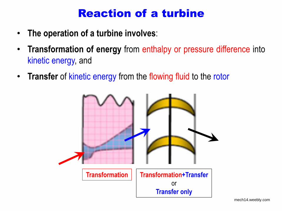
Reaction of a turbine
• The operation of a turbine involves:
• Transformation of energy from enthalpy or pressure difference into
kinetic energy, and
• Transfer of kinetic energy from the flowing fluid to the rotor
Transformation Transformation+Transfer
or
Transfer only mech14.weebly.com
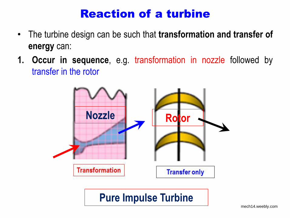
Reaction of a turbine
• The turbine design can be such that transformation and transfer of
energy can:
1. Occur in sequence, e.g. transformation in nozzle followed by
transfer in the rotor
Rotor
Pure Impulse Turbine
Nozzle
mech14.weebly.com
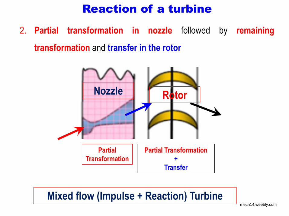
Reaction of a turbine
2. Partial transformation in nozzle followed by remaining
transformation and transfer in the rotor
Partial
Transformation
Partial Transformation
+
Transfer
Nozzle Rotor
Mixed flow (Impulse + Reaction) Turbine mech14.weebly.com
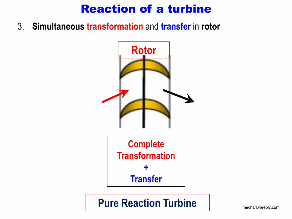
Reaction of a turbine
3. Simultaneous transformation and transfer in rotor
Complete
Transformation
+
Transfer
Rotor
Pure Reaction Turbine mech14.weebly.com
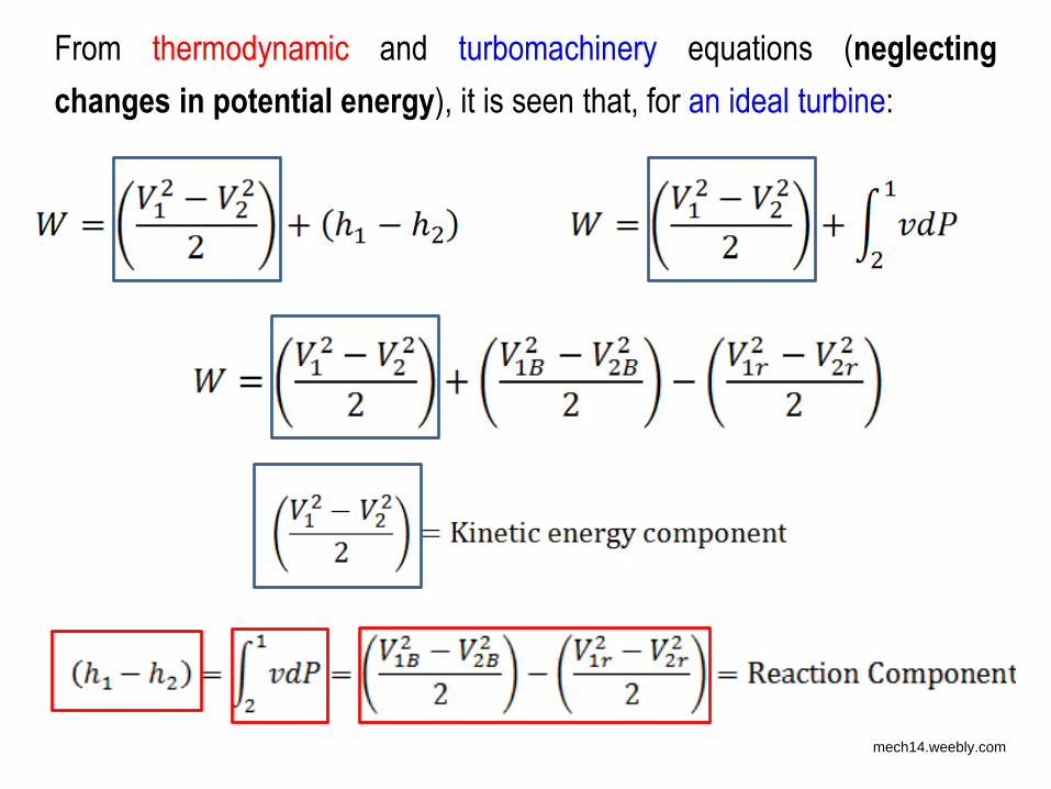
From thermodynamic and turbomachinery equations (neglecting
changes in potential energy), it is seen that, for an ideal turbine:
mech14.weebly.com
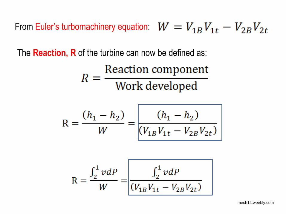
From Euler’s turbomachinery equation:
The Reaction, R of the turbine can now be defined as:
mech14.weebly.com
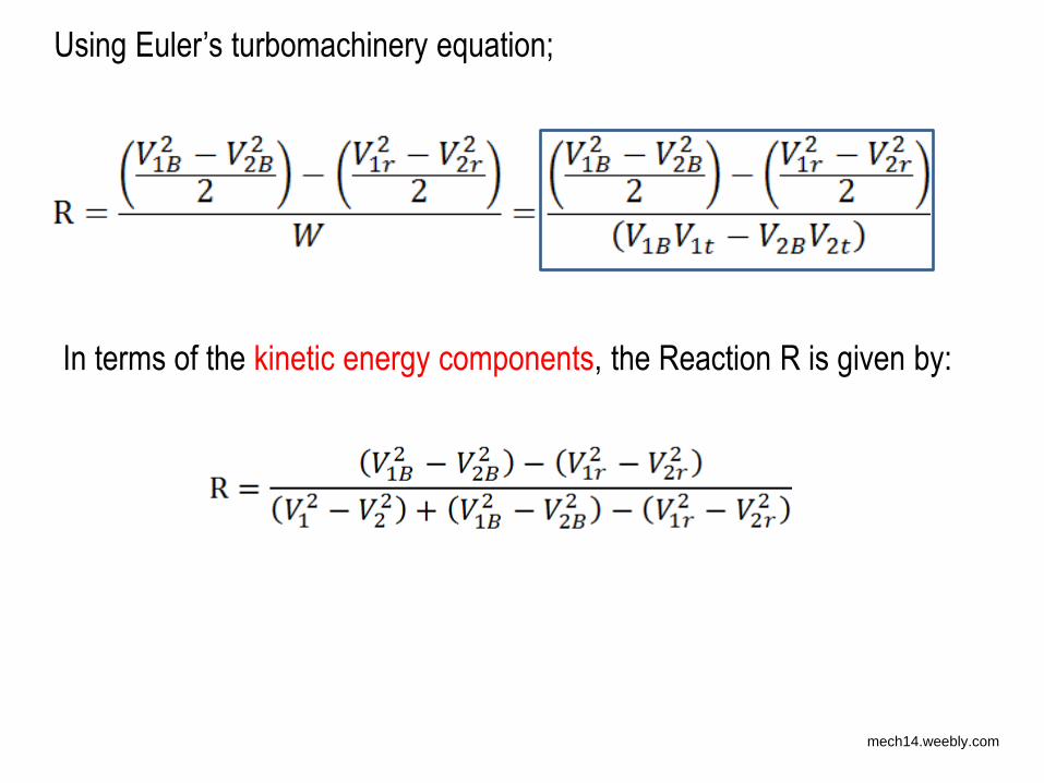
In terms of the kinetic energy components, the Reaction R is given by:
Using Euler’s turbomachinery equation;
mech14.weebly.com
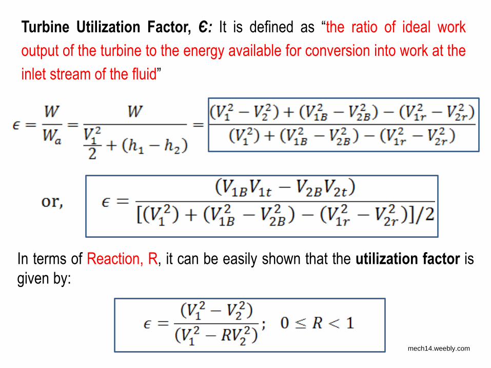
Turbine Utilization Factor, Є: It is defined as “the ratio of ideal work
output of the turbine to the energy available for conversion into work at the
inlet stream of the fluid”
In terms of Reaction, R, it can be easily shown that the utilization factor is
given by:
mech14.weebly.com
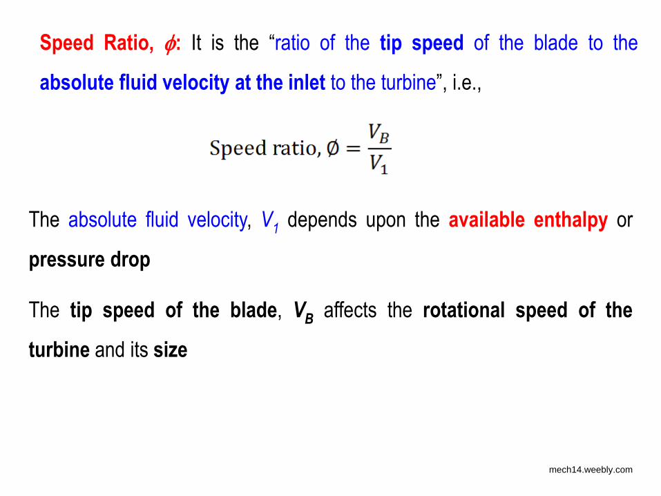
Speed Ratio, : It is the “ratio of the tip speed of the blade to the
absolute fluid velocity at the inlet to the turbine”, i.e.,
The absolute fluid velocity, V1 depends upon the available enthalpy or
pressure drop
The tip speed of the blade, VB affects the rotational speed of the
turbine and its size
mech14.weebly.com
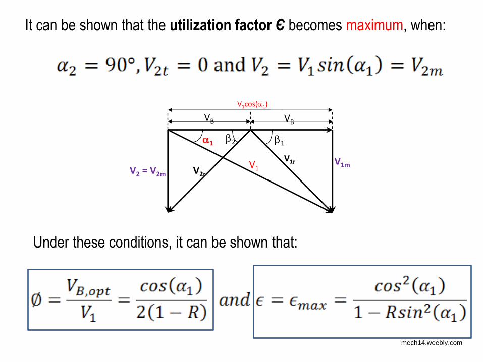
It can be shown that the utilization factor Є becomes maximum, when:
1 1 2
V1cos(1)
VB VB
V1r V2 = V2m
V1 V2r V1m
Under these conditions, it can be shown that:
mech14.weebly.com
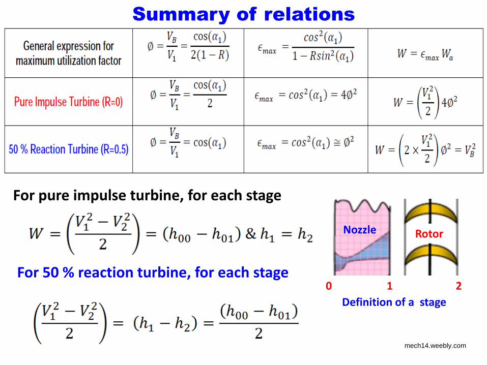
Summary of relations
For pure impulse turbine, for each stage
For 50 % reaction turbine, for each stage 0 1 2
Definition of a stage
Nozzle Rotor
mech14.weebly.com
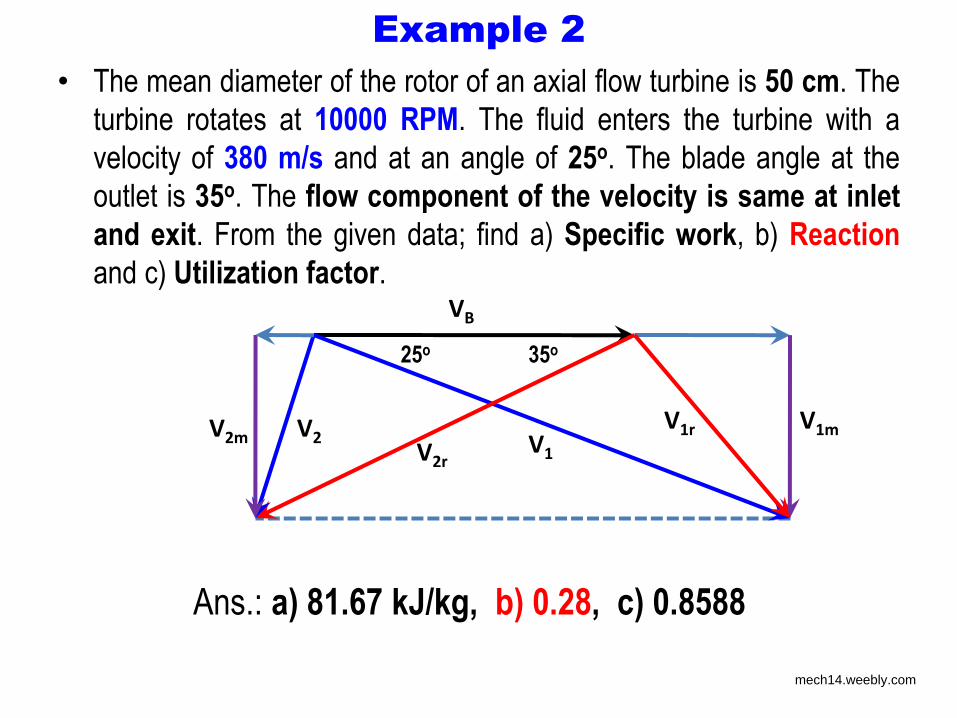
Example 2
• The mean diameter of the rotor of an axial flow turbine is 50 cm. The
turbine rotates at 10000 RPM. The fluid enters the turbine with a
velocity of 380 m/s and at an angle of 25o. The blade angle at the
outlet is 35o. The flow component of the velocity is same at inlet
and exit. From the given data; find a) Specific work, b) Reaction
and c) Utilization factor. VB
V1
V1m V2m V2 V1r
V2r
25o 35o
Ans.: a) 81.67 kJ/kg, b) 0.28, c) 0.8588
mech14.weebly.com
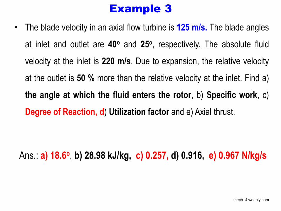
Example 3
• The blade velocity in an axial flow turbine is 125 m/s. The blade angles
at inlet and outlet are 40o and 25o, respectively. The absolute fluid
velocity at the inlet is 220 m/s. Due to expansion, the relative velocity
at the outlet is 50 % more than the relative velocity at the inlet. Find a)
the angle at which the fluid enters the rotor, b) Specific work, c)
Degree of Reaction, d) Utilization factor and e) Axial thrust.
Ans.: a) 18.6o, b) 28.98 kJ/kg, c) 0.257, d) 0.916, e) 0.967 N/kg/s
mech14.weebly.com
Single stage impulse turbines
• Single stage impulse turbine is one of the simplest form of a steam
turbine
• It is also called as De Laval turbines, after its inventor
• A single stage impulse turbine consists of a single rotor, usually
rotating at very high RPM
• The blades are usually symmetrical, with inlet and exit blade
angles of around 20o
• Steam is fed to the turbine rotor through one or more numbers of
convergent-divergent nozzles
• More than one inlet nozzles provides the possibility of governing
the turbine, by closing one or more of the nozzles
mech14.weebly.com
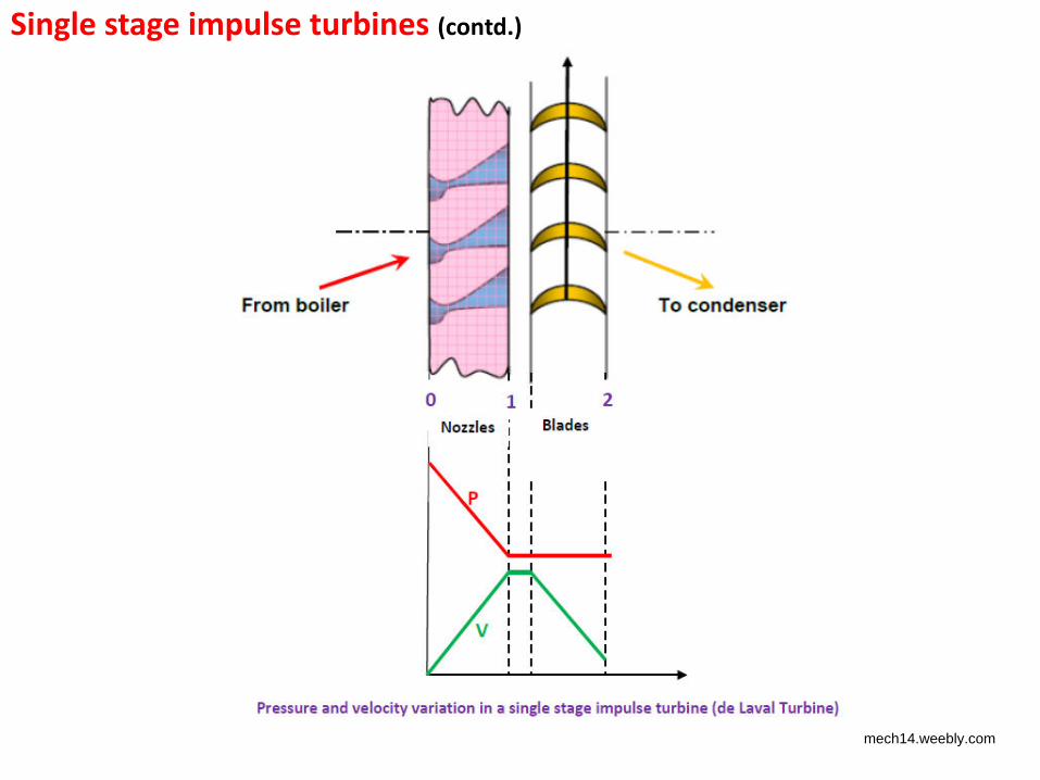
Single stage impulse turbines (contd.)
mech14.weebly.com
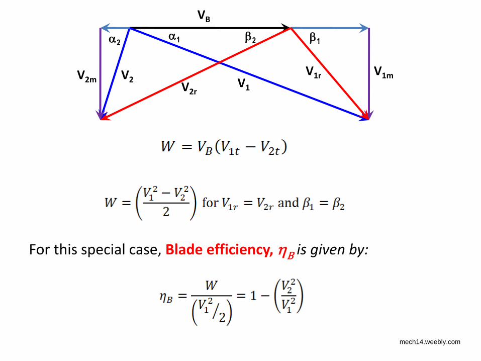
For this special case, Blade efficiency, B is given by:
VB
V1
V1m V2m V2 V1r
V2r
1 2 1 2
mech14.weebly.com
VB
V1
V1m V2m V2 V1r
V2r
1 2 1 2
For this special case,
mech14.weebly.com
VB
V1
V1m V2m V2 V1r
V2r
1 2 1 2
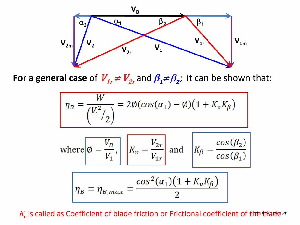
For a general case of V1r V2r and 1 2; it can be shown that:
Kv is called as Coefficient of blade friction or Frictional coefficient of the blade mech14.weebly.com
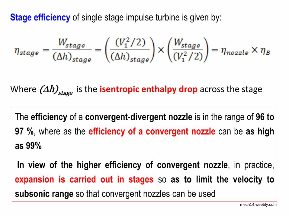
Stage efficiency of single stage impulse turbine is given by:
Where (h)stage is the isentropic enthalpy drop across the stage
The efficiency of a convergent-divergent nozzle is in the range of 96 to
97 %, where as the efficiency of a convergent nozzle can be as high
as 99%
In view of the higher efficiency of convergent nozzle, in practice,
expansion is carried out in stages so as to limit the velocity to
subsonic range so that convergent nozzles can be used mech14.weebly.com
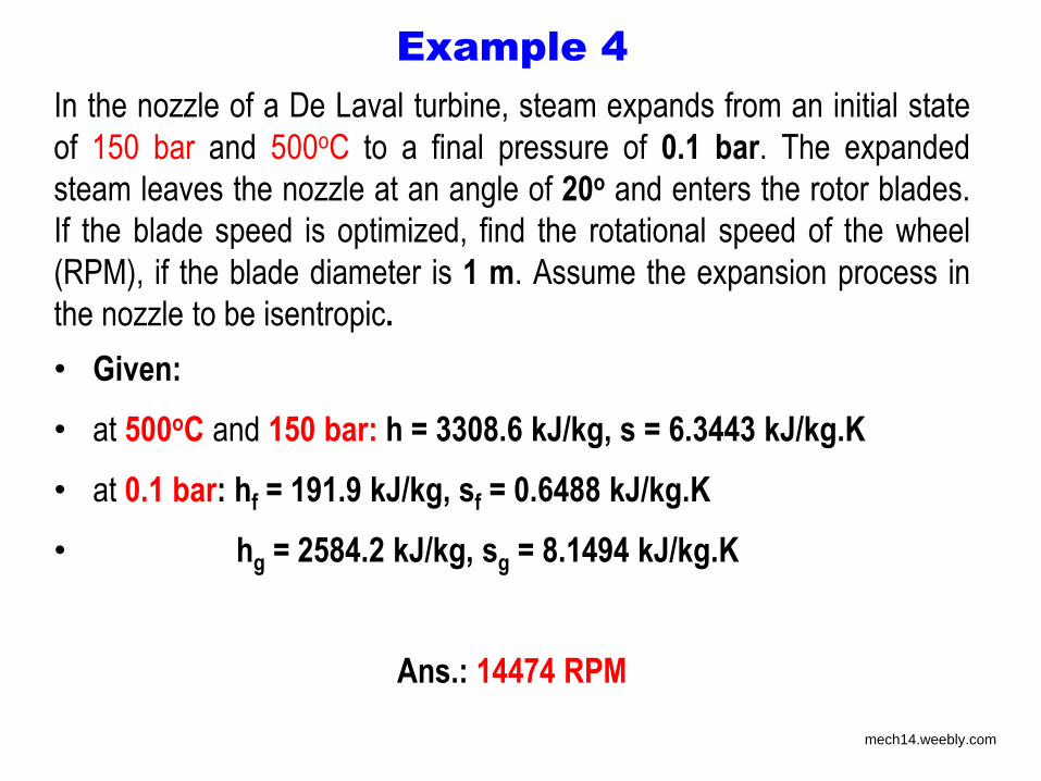
In the nozzle of a De Laval turbine, steam expands from an initial state
of 150 bar and 500oC to a final pressure of 0.1 bar. The expanded
steam leaves the nozzle at an angle of 20o and enters the rotor blades.
If the blade speed is optimized, find the rotational speed of the wheel
(RPM), if the blade diameter is 1 m. Assume the expansion process in
the nozzle to be isentropic.
• Given:
• at 500oC and 150 bar: h = 3308.6 kJ/kg, s = 6.3443 kJ/kg.K
• at 0.1 bar: hf = 191.9 kJ/kg, sf = 0.6488 kJ/kg.K
• hg = 2584.2 kJ/kg, sg = 8.1494 kJ/kg.K
Ans.: 14474 RPM
Example 4
mech14.weebly.com
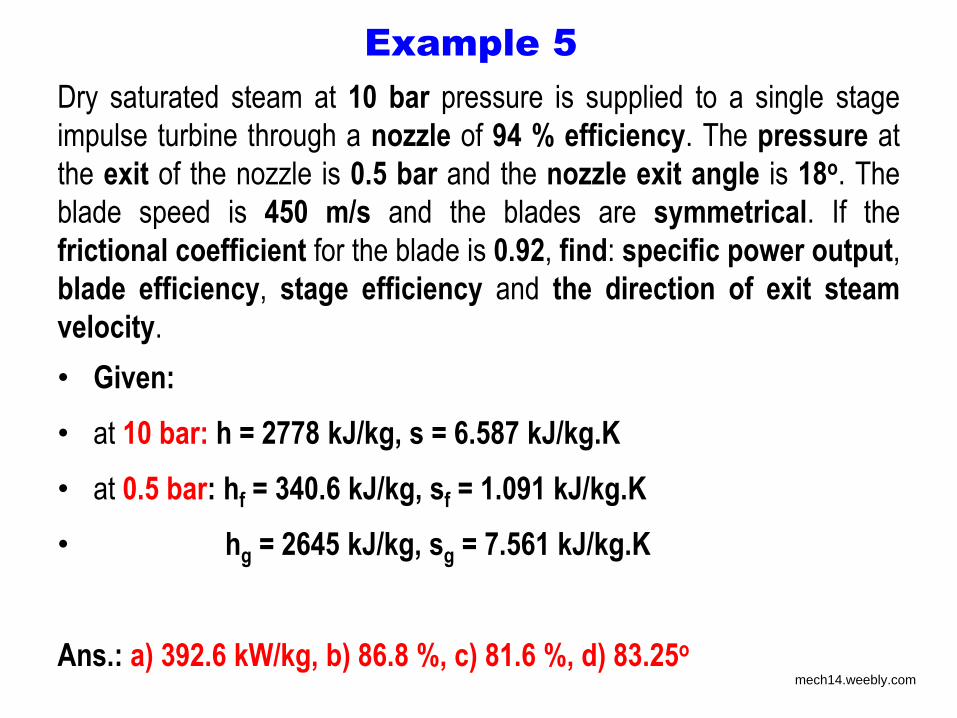
Dry saturated steam at 10 bar pressure is supplied to a single stage
impulse turbine through a nozzle of 94 % efficiency. The pressure at
the exit of the nozzle is 0.5 bar and the nozzle exit angle is 18o. The
blade speed is 450 m/s and the blades are symmetrical. If the
frictional coefficient for the blade is 0.92, find: specific power output,
blade efficiency, stage efficiency and the direction of exit steam
velocity.
• Given:
• at 10 bar: h = 2778 kJ/kg, s = 6.587 kJ/kg.K
• at 0.5 bar: hf = 340.6 kJ/kg, sf = 1.091 kJ/kg.K
• hg = 2645 kJ/kg, sg = 7.561 kJ/kg.K
Ans.: a) 392.6 kW/kg, b) 86.8 %, c) 81.6 %, d) 83.25o
Example 5
mech14.weebly.com
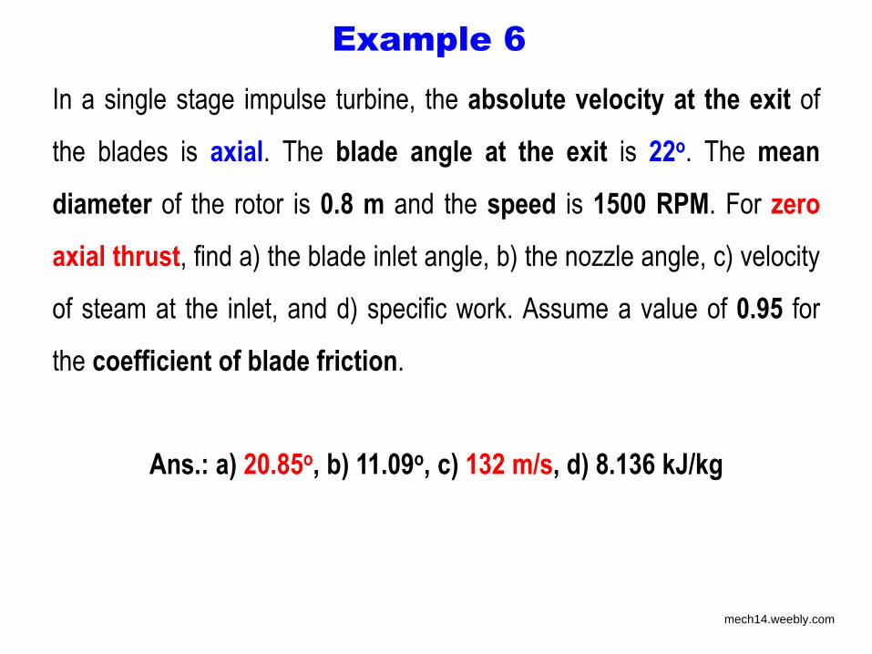
In a single stage impulse turbine, the absolute velocity at the exit of
the blades is axial. The blade angle at the exit is 22o. The mean
diameter of the rotor is 0.8 m and the speed is 1500 RPM. For zero
axial thrust, find a) the blade inlet angle, b) the nozzle angle, c) velocity
of steam at the inlet, and d) specific work. Assume a value of 0.95 for
the coefficient of blade friction.
Ans.: a) 20.85o, b) 11.09o, c) 132 m/s, d) 8.136 kJ/kg
Example 6
mech14.weebly.com
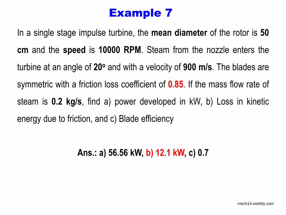
In a single stage impulse turbine, the mean diameter of the rotor is 50
cm and the speed is 10000 RPM. Steam from the nozzle enters the
turbine at an angle of 20o and with a velocity of 900 m/s. The blades are
symmetric with a friction loss coefficient of 0.85. If the mass flow rate of
steam is 0.2 kg/s, find a) power developed in kW, b) Loss in kinetic
energy due to friction, and c) Blade efficiency
Ans.: a) 56.56 kW, b) 12.1 kW, c) 0.7
Example 7
mech14.weebly.com
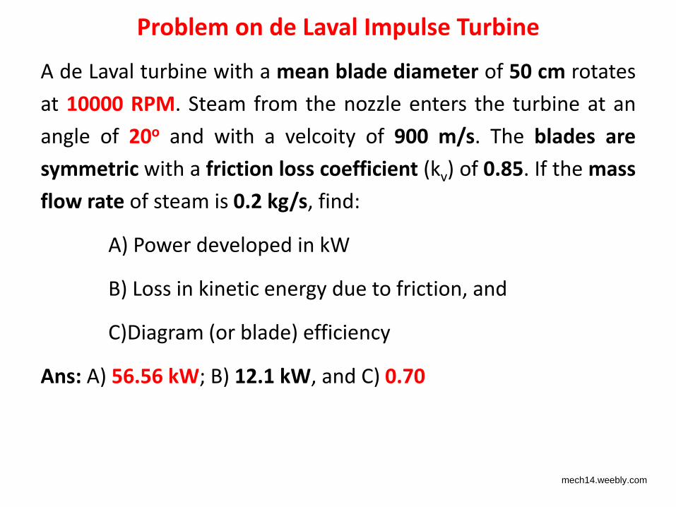
Problem on de Laval Impulse Turbine
A de Laval turbine with a mean blade diameter of 50 cm rotates
at 10000 RPM. Steam from the nozzle enters the turbine at an
angle of 20o and with a velcoity of 900 m/s. The blades are
symmetric with a friction loss coefficient (kv) of 0.85. If the mass
flow rate of steam is 0.2 kg/s, find:
A) Power developed in kW
B) Loss in kinetic energy due to friction, and
C)Diagram (or blade) efficiency
Ans: A) 56.56 kW; B) 12.1 kW, and C) 0.70
mech14.weebly.com

Problems with single stage impulse turbine
• Very high rotational speeds (as high as 30000 RPM)
– Extremely high blade stresses
• Need for thick and strong blades and suitable materials
– Large fluid and mechanical frictional losses
• Low efficiency
– Need for bulky and expensive gear trains as the electrical
alternators generally operate at a fixed RPM of 3000/3600 RPM
• To keep the blade stresses within acceptable limits, the tip speeds are
usually limited to about 400 m/s
mech14.weebly.com
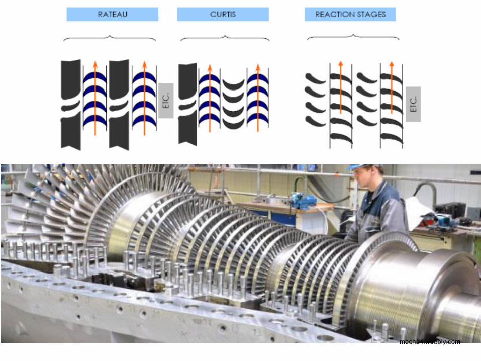
Compounding or staging of impulse turbines
• Compounding or staging of impulse turbines is done to obtain
reasonable blade speeds for the same overall pressure drop
• Compounding can be:
1. Velocity compounding – Curtis stage
2. Pressure compounding – Rateau stage
3. Combination of Curtis and Rateau stages
mech14.weebly.com
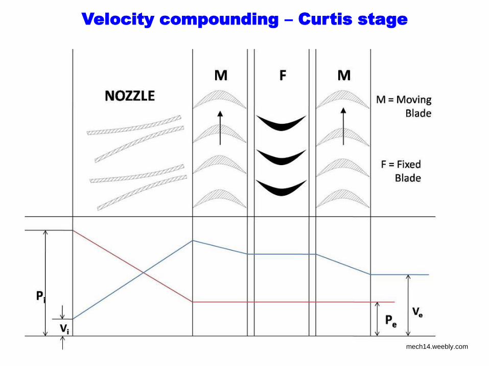
Velocity compounding – Curtis stage
• All the pressure drop takes place in the stationary nozzle itself
and the absolute fluid velocity is maximum at the inlet to the 1st
rotor
• The fluid velocity decreases in stages across a series of rotor
blades
• Each rotor blade is followed by a fixed guide blade
• Ideally there is no change in the magnitude of fluid velocity across
the fixed guide blade, there is change in direction only
• Pressure remains constant across the rotor and fixed guide blades
mech14.weebly.com
Velocity compounding – Curtis stage
mech14.weebly.com
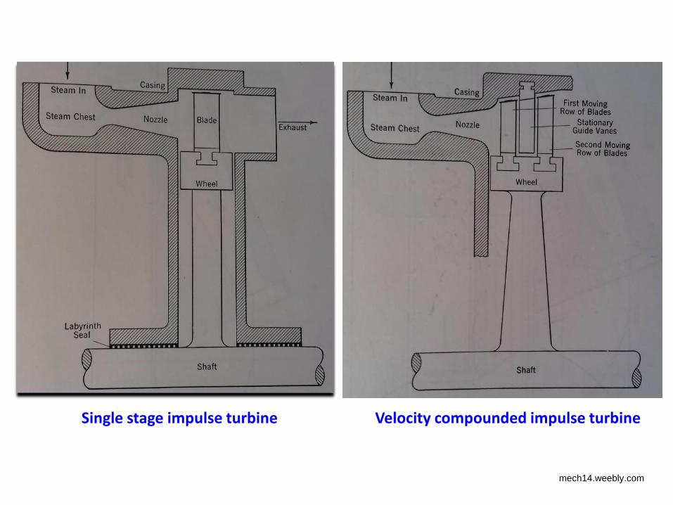
Single stage impulse turbine Velocity compounded impulse turbine
mech14.weebly.com
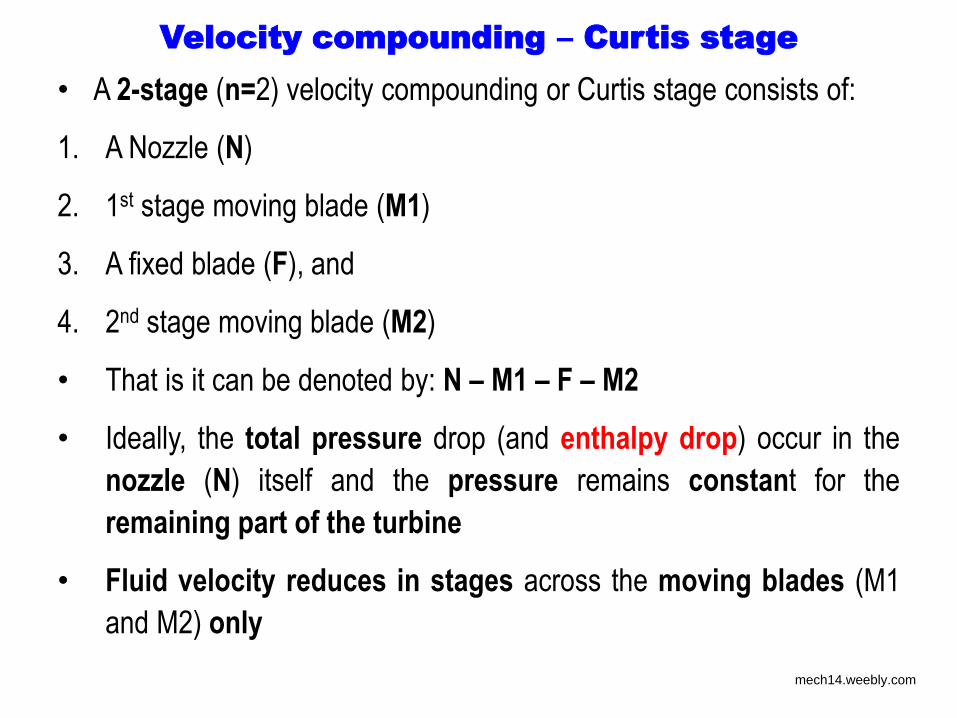
Velocity compounding – Curtis stage
• A 2-stage (n=2) velocity compounding or Curtis stage consists of:
1. A Nozzle (N)
2. 1st stage moving blade (M1)
3. A fixed blade (F), and
4. 2nd stage moving blade (M2)
• That is it can be denoted by: N – M1 – F – M2
• Ideally, the total pressure drop (and enthalpy drop) occur in the
nozzle (N) itself and the pressure remains constant for the
remaining part of the turbine
• Fluid velocity reduces in stages across the moving blades (M1
and M2) only
mech14.weebly.com
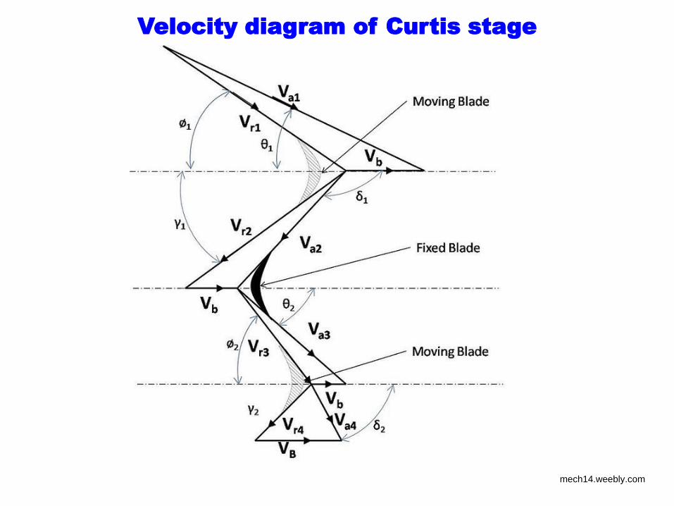
Velocity diagram of Curtis stage
mech14.weebly.com
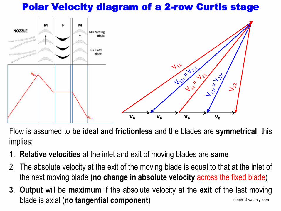
Polar Velocity diagram of a 2-row Curtis stage
Flow is assumed to be ideal and frictionless and the blades are symmetrical, this
implies:
1. Relative velocities at the inlet and exit of moving blades are same
2. The absolute velocity at the exit of the moving blade is equal to that at the inlet of
the next moving blade (no change in absolute velocity across the fixed blade)
3. Output will be maximum if the absolute velocity at the exit of the last moving
blade is axial (no tangential component)
VB VB VB VB
mech14.weebly.com
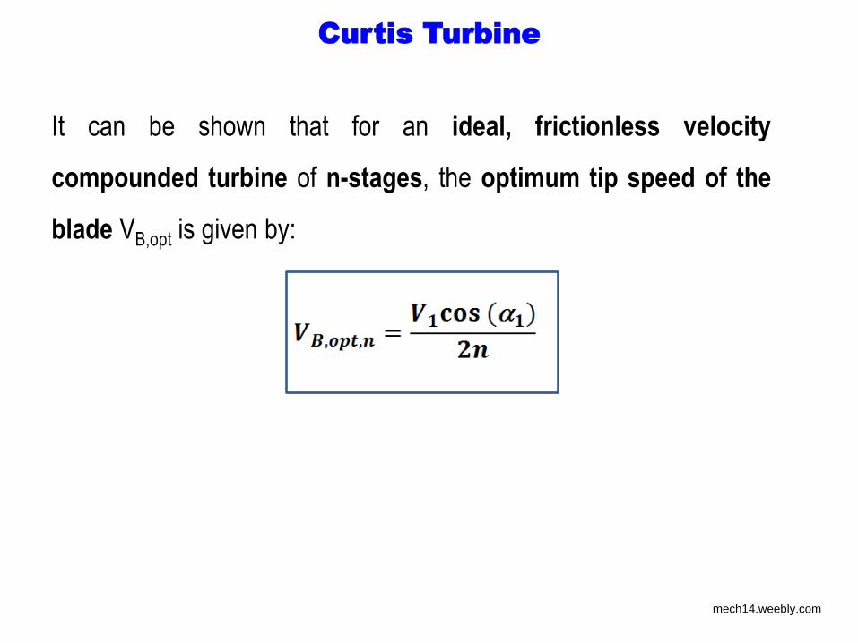
Curtis Turbine
It can be shown that for an ideal, frictionless velocity
compounded turbine of n-stages, the optimum tip speed of the
blade VB,opt is given by:
mech14.weebly.com
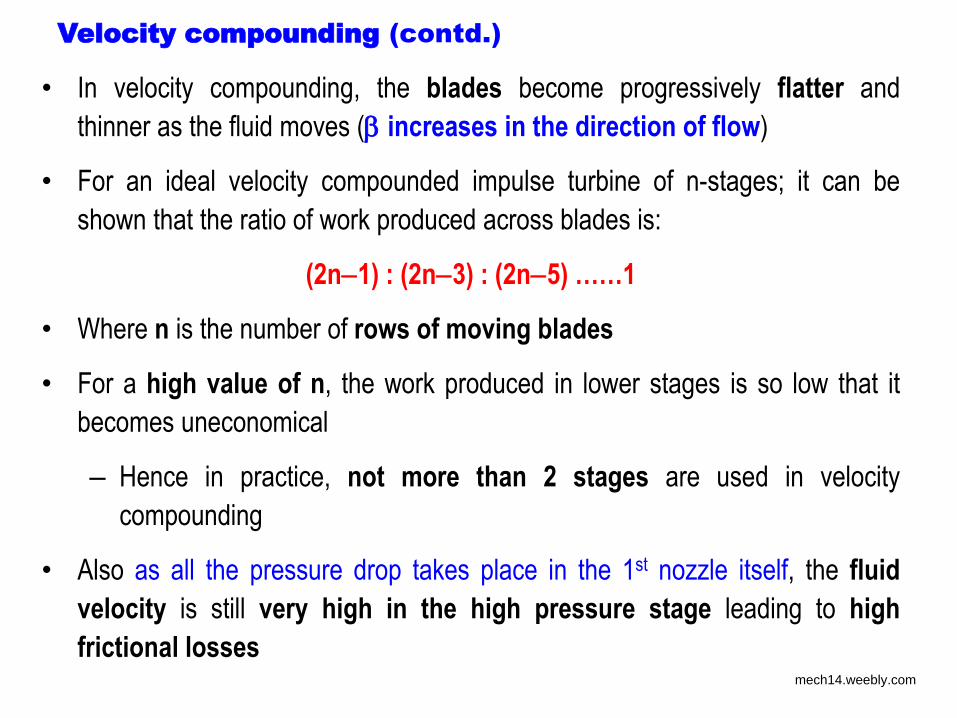
Velocity compounding (contd.)
• In velocity compounding, the blades become progressively flatter and
thinner as the fluid moves ( increases in the direction of flow)
• For an ideal velocity compounded impulse turbine of n-stages; it can be
shown that the ratio of work produced across blades is:
(2n1) : (2n3) : (2n5) ……1
• Where n is the number of rows of moving blades
• For a high value of n, the work produced in lower stages is so low that it
becomes uneconomical
– Hence in practice, not more than 2 stages are used in velocity
compounding
• Also as all the pressure drop takes place in the 1st nozzle itself, the fluid
velocity is still very high in the high pressure stage leading to high
frictional losses mech14.weebly.com
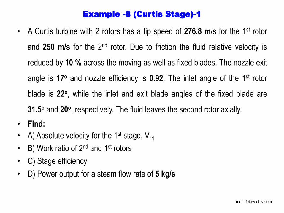
Example -8 (Curtis Stage)-1
• A Curtis turbine with 2 rotors has a tip speed of 276.8 m/s for the 1st rotor
and 250 m/s for the 2nd rotor. Due to friction the fluid relative velocity is
reduced by 10 % across the moving as well as fixed blades. The nozzle exit
angle is 17o and nozzle efficiency is 0.92. The inlet angle of the 1st rotor
blade is 22o, while the inlet and exit blade angles of the fixed blade are
31.5o and 20o, respectively. The fluid leaves the second rotor axially.
• Find:
• A) Absolute velocity for the 1st stage, V11
• B) Work ratio of 2nd and 1st rotors
• C) Stage efficiency
• D) Power output for a steam flow rate of 5 kg/s
mech14.weebly.com
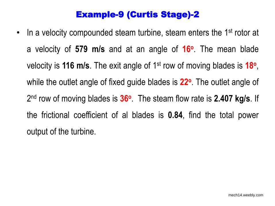
Example-9 (Curtis Stage)-2
• In a velocity compounded steam turbine, steam enters the 1st rotor at
a velocity of 579 m/s and at an angle of 16o. The mean blade
velocity is 116 m/s. The exit angle of 1st row of moving blades is 18o,
while the outlet angle of fixed guide blades is 22o. The outlet angle of
2nd row of moving blades is 36o. The steam flow rate is 2.407 kg/s. If
the frictional coefficient of al blades is 0.84, find the total power
output of the turbine.
mech14.weebly.com
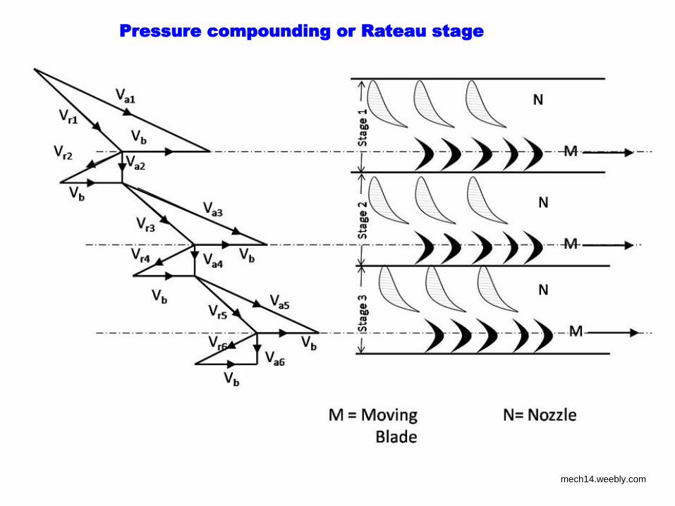
Pressure compounding or Rateau stage
• In a pressure compounded impulse turbine, called as Rateau
stage, the pressure drop is divided among different stages
• One single Rateau stage consists of:
1. A nozzle from which steam enters the turbine (N)
2. 1st stage moving blade (M1) across which pressure remains
constant and velocity decreases
3. A fixed blade (F) which acts as a nozzle, and
4. 2nd stage moving blade (M2)
mech14.weebly.com
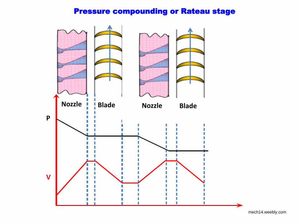
Pressure compounding or Rateau stage
Blade Nozzle Nozzle Blade
P
V
mech14.weebly.com
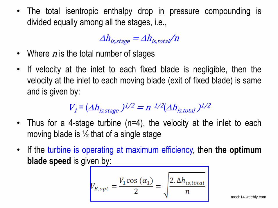
• The total isentropic enthalpy drop in pressure compounding is
divided equally among all the stages, i.e.,
his,stage = his,total/n
• Where n is the total number of stages
• If velocity at the inlet to each fixed blade is negligible, then the
velocity at the inlet to each moving blade (exit of fixed blade) is same
and is given by:
V1 = (his,stage )1/2 = n1/2(his,total )1/2
• Thus for a 4-stage turbine (n=4), the velocity at the inlet to each
moving blade is ½ that of a single stage
• If the turbine is operating at maximum efficiency, then the optimum
blade speed is given by:
mech14.weebly.com
Pressure compounding or Rateau stage
mech14.weebly.com
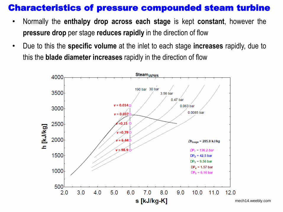
Characteristics of pressure compounded steam turbine
• Normally the enthalpy drop across each stage is kept constant, however the
pressure drop per stage reduces rapidly in the direction of flow
• Due to this the specific volume at the inlet to each stage increases rapidly, due to
this the blade diameter increases rapidly in the direction of flow
v = 0.014
v = 0.037
v =0.15
v =0.79
v = 6.44
v = 98.9
mech14.weebly.com
Characteristics of pressure compounded steam turbine (contd.)
• Reduced fluid and blade velocities
– Reduced fluid friction
– Reduced solid friction
• Higher efficiency
– Less requirement of gearing
• Equal work per stage or work per stage as per requirement
• Greater possibility of steam leakage due to need for pressure reduction
across fixed blades/nozzles
– Need for leak-proof design
• Increased number of stages due to limited pressure drop across each stage
• Due to higher efficiency and higher initial cost, pressure compounding
is normally used in large capacity systems
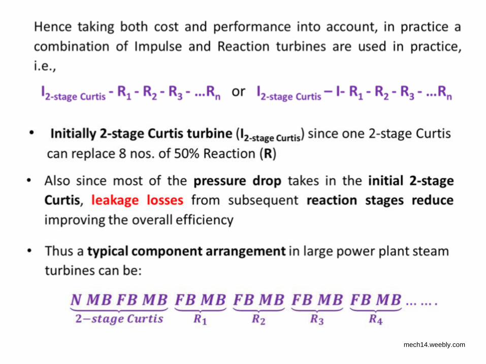
• A good compromise is to use 1 or 2 Curtis stages followed by Rateau
stages
mech14.weebly.com
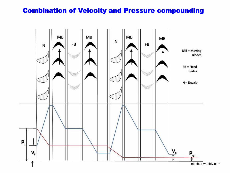
Combination of Velocity and Pressure compounding
mech14.weebly.com
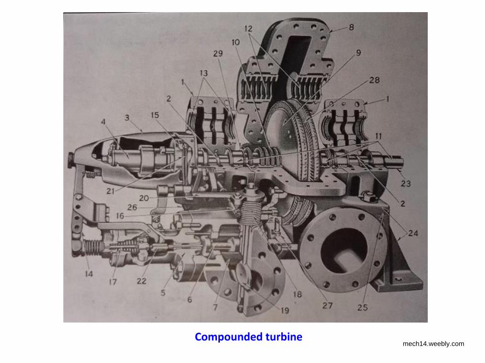
Compounded turbine mech14.weebly.com
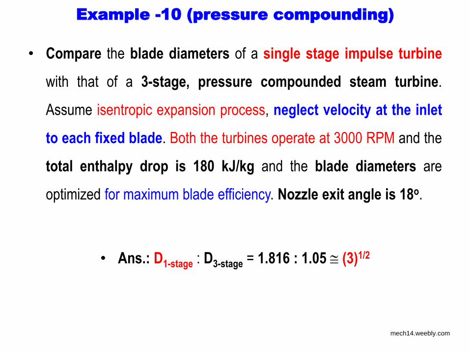
Example -10 (pressure compounding)
• Compare the blade diameters of a single stage impulse turbine
with that of a 3-stage, pressure compounded steam turbine.
Assume isentropic expansion process, neglect velocity at the inlet
to each fixed blade. Both the turbines operate at 3000 RPM and the
total enthalpy drop is 180 kJ/kg and the blade diameters are
optimized for maximum blade efficiency. Nozzle exit angle is 18o.
• Ans.: D1-stage : D3-stage = 1.816 : 1.05 (3)1/2
mech14.weebly.com
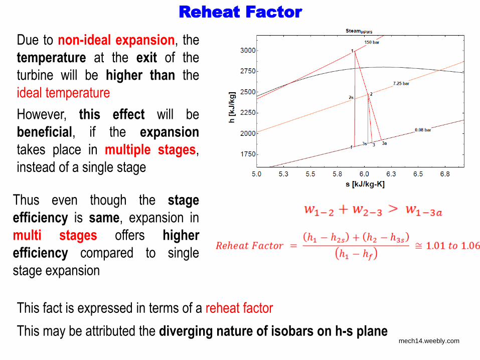
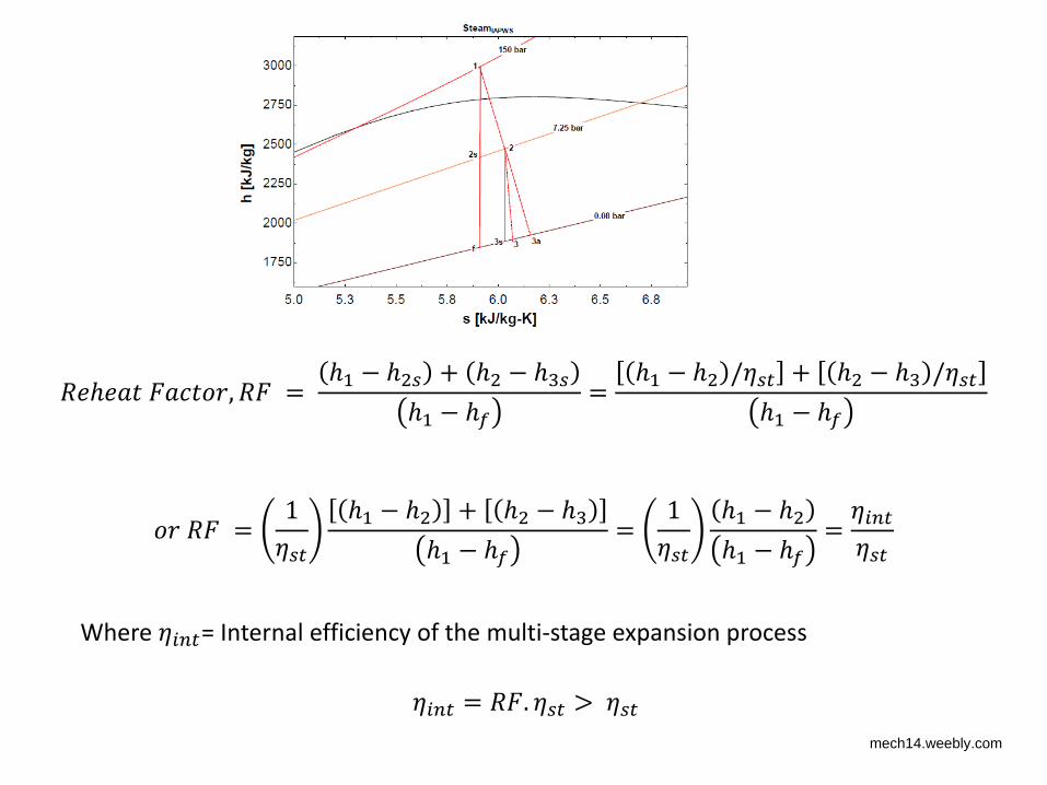
Reheat Factor
Due to non-ideal expansion, the
temperature at the exit of the
turbine will be higher than the
ideal temperature
However, this effect will be
beneficial, if the expansion
takes place in multiple stages,
instead of a single stage
Thus even though the stage
efficiency is same, expansion in
multi stages offers higher
efficiency compared to single
stage expansion
This fact is expressed in terms of a reheat factor
This may be attributed the diverging nature of isobars on h-s plane mech14.weebly.com
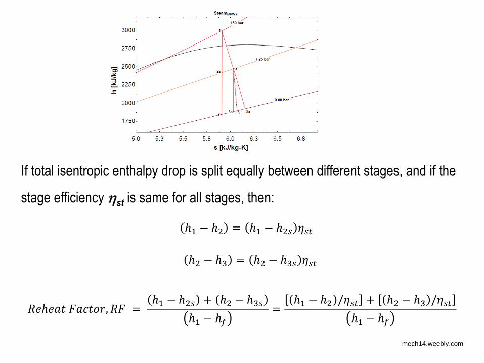
If total isentropic enthalpy drop is split equally between different stages, and if the
stage efficiency st is same for all stages, then: ℎ − ℎ = ℎ − ℎ 𝜂 ℎ − ℎ = ℎ − ℎ 𝜂
𝑅 ℎ 𝑎 𝑎 , 𝑅 = ℎ − ℎ + ℎ − ℎℎ − ℎ𝑓 = ℎ − ℎ /𝜂 + ℎ − ℎ /𝜂ℎ − ℎ𝑓
mech14.weebly.com
𝑅 ℎ 𝑎 𝑎 , 𝑅 = ℎ − ℎ + ℎ − ℎℎ − ℎ𝑓 = ℎ − ℎ /𝜂 + ℎ − ℎ /𝜂ℎ − ℎ𝑓
𝑅 = 𝜂 ℎ − ℎ + ℎ − ℎℎ − ℎ𝑓 = 𝜂 ℎ − ℎℎ − ℎ𝑓 = 𝜂𝑖𝜂
Where 𝜂𝑖 = Internal efficiency of the multi-stage expansion process 𝜂𝑖 = 𝑅 . 𝜂 > 𝜂
mech14.weebly.com
Example -11 (Pressure compounding)
• An impulse steam turbine has a number of pressure stages each having a row
of nozzles and a single ring of blades. The nozzle angle in the 1st stage is 20o
and the blade exit angle is 30o. The mean blade speed is 130 m/s and the
velocity of steam leaving the nozzle is 330 m/s.
a) Taking the blade friction factor as 0.8 and nozzle efficiency of 0.85, find work
done in the stage per kg of steam and stage efficiency
b) If steam is supplied to 1st stage at 20 bar and 250o C and the condenser
pressure is 0.07 bar, estimate the required number of stages assuming equal
stage efficiency and work done. The reheat factor is 1.06.
Ans.: a) 42.55 kJ/kg and 0.6643
b) 15
mech14.weebly.com
Reaction Turbines
mech14.weebly.com
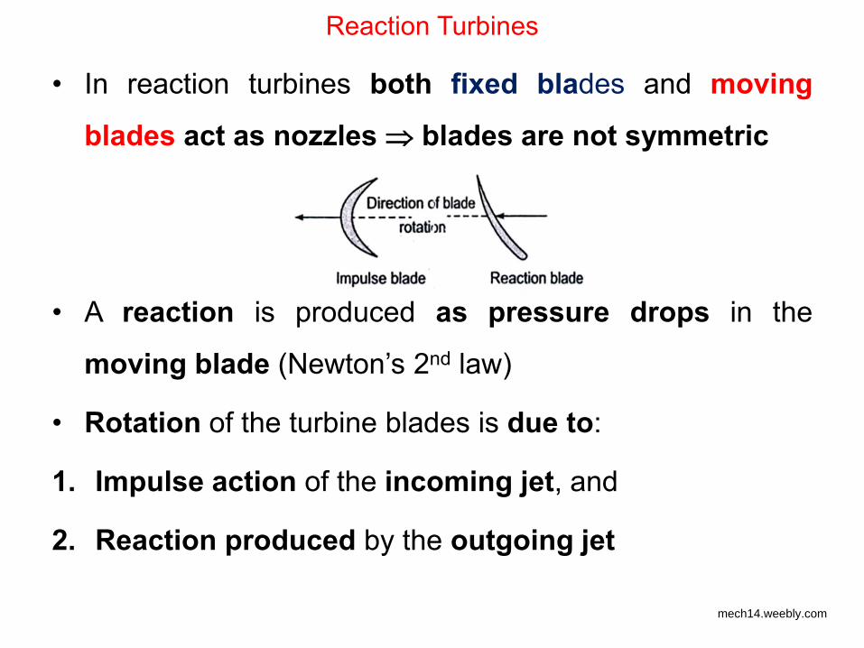
Reaction Turbines
• In reaction turbines both fixed blades and moving
blades act as nozzles blades are not symmetric
• A reaction is produced as pressure drops in the
moving blade (Newton’s 2nd law)
• Rotation of the turbine blades is due to:
1. Impulse action of the incoming jet, and
2. Reaction produced by the outgoing jet
mech14.weebly.com
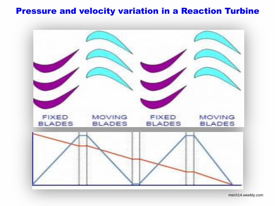
Pressure and velocity variation in a Reaction Turbine
mech14.weebly.com
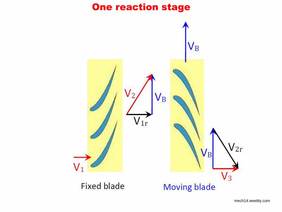
One reaction stage
mech14.weebly.com
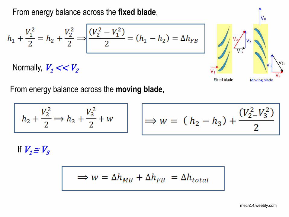
From energy balance across the fixed blade,
From energy balance across the moving blade,
Normally, V1 << V2
If V1 V3
mech14.weebly.com
mech14.weebly.com
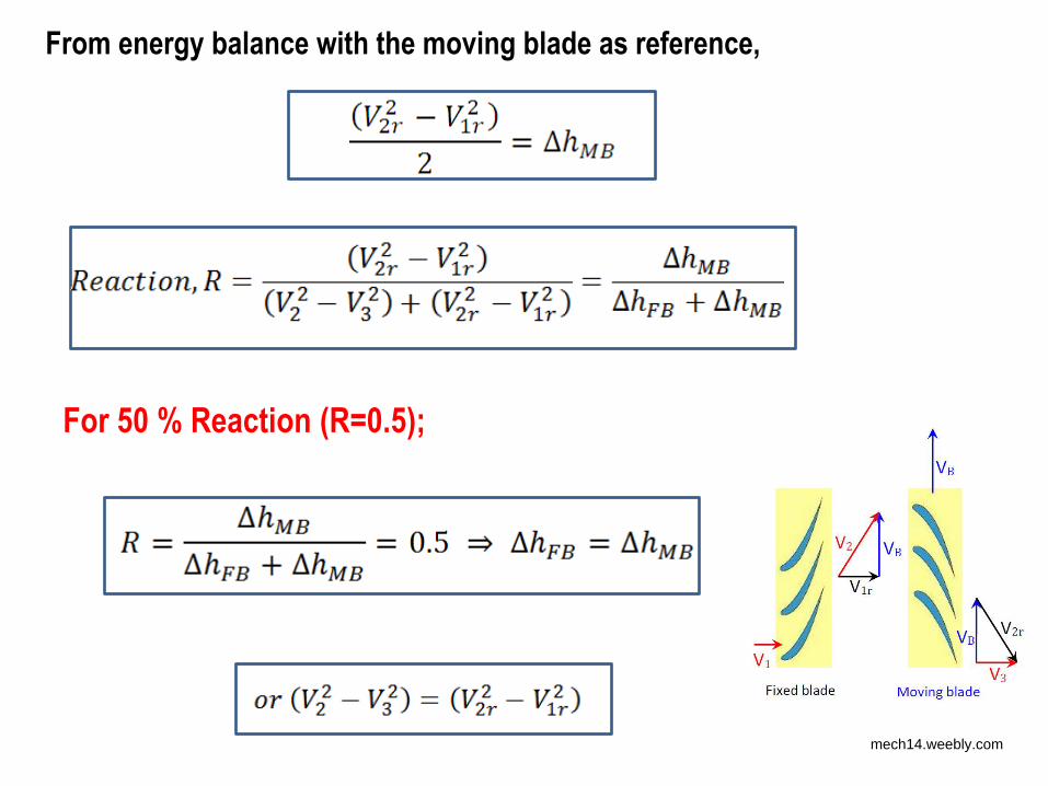
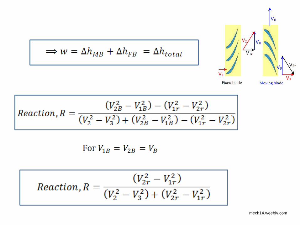
From energy balance with the moving blade as reference,
For 50 % Reaction (R=0.5);
mech14.weebly.com
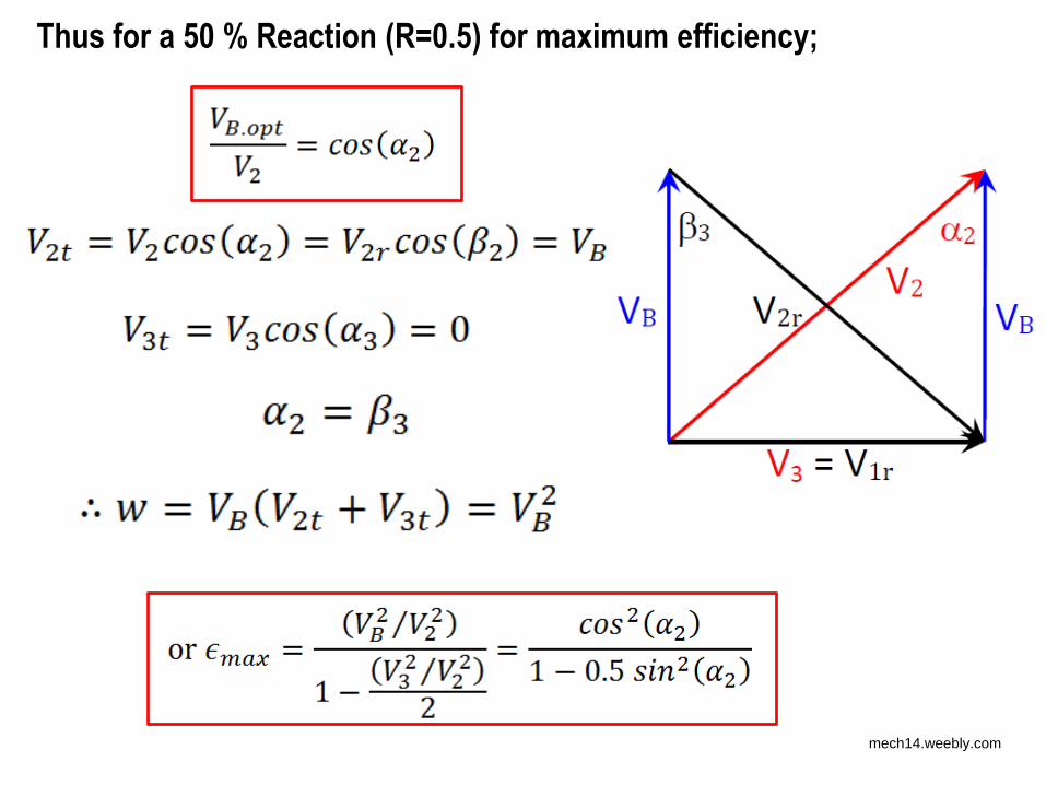
Thus for a 50 % Reaction (R=0.5) for maximum efficiency;
mech14.weebly.com
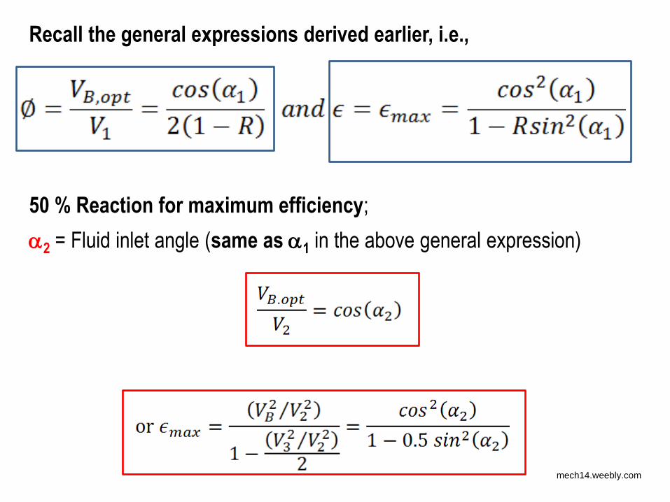
50 % Reaction for maximum efficiency;
2 = Fluid inlet angle (same as 1 in the above general expression)
Recall the general expressions derived earlier, i.e.,
mech14.weebly.com
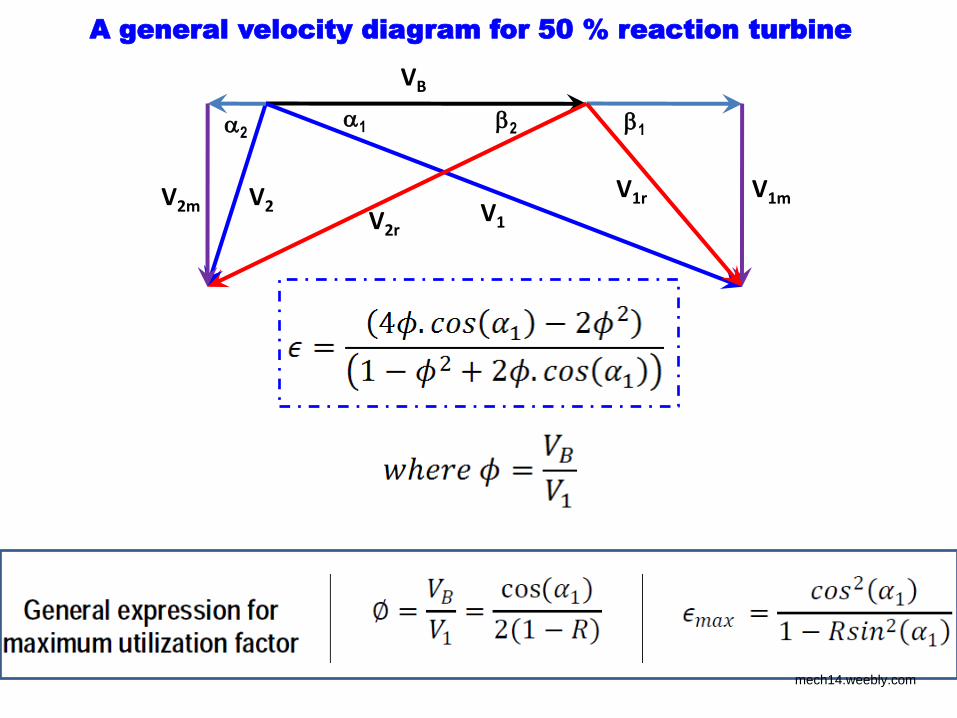
A general velocity diagram for 50 % reaction turbine
VB
V1
V1m V2m V2 V1r
V2r
1 2 1 2
mech14.weebly.com
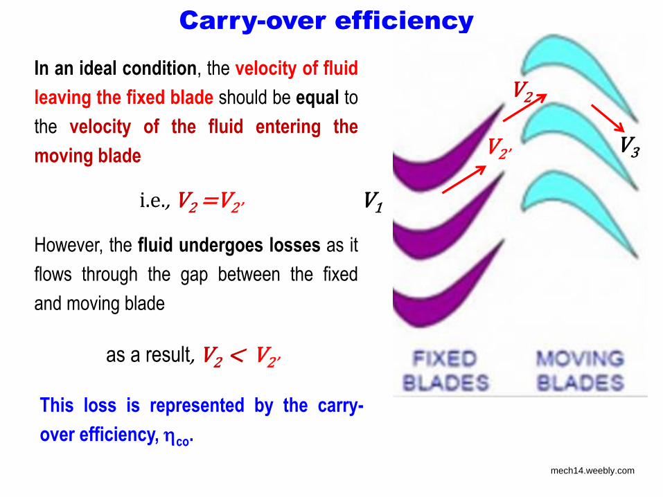
Carry-over efficiency
V3
V1
V ’ V2
In an ideal condition, the velocity of fluid
leaving the fixed blade should be equal to
the velocity of the fluid entering the
moving blade
i.e., V2 =V ’ However, the fluid undergoes losses as it
flows through the gap between the fixed
and moving blade
as a result, V2 < V ’ This loss is represented by the carry-
over efficiency, co.
mech14.weebly.com
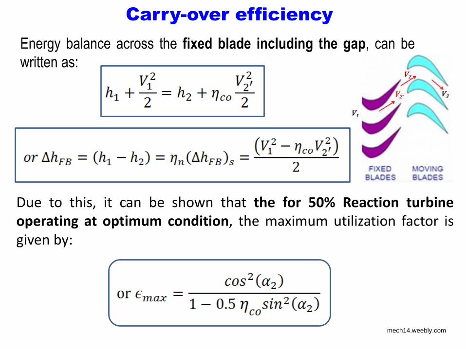
Carry-over efficiency
Energy balance across the fixed blade including the gap, can be
written as:
Due to this, it can be shown that the for 50% Reaction turbine
operating at optimum condition, the maximum utilization factor is
given by:
mech14.weebly.com
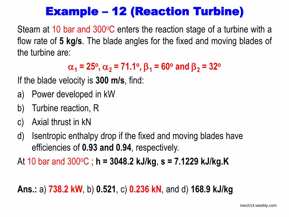
Example – 12 (Reaction Turbine)
Steam at 10 bar and 300oC enters the reaction stage of a turbine with a
flow rate of 5 kg/s. The blade angles for the fixed and moving blades of
the turbine are:
1 = 25o, 2 = 71.1o, 1 = 60o and 2 = 32o
If the blade velocity is 300 m/s, find:
a) Power developed in kW
b) Turbine reaction, R
c) Axial thrust in kN
d) Isentropic enthalpy drop if the fixed and moving blades have
efficiencies of 0.93 and 0.94, respectively.
At 10 bar and 300oC ; h = 3048.2 kJ/kg, s = 7.1229 kJ/kg.K
Ans.: a) 738.2 kW, b) 0.521, c) 0.236 kN, and d) 168.9 kJ/kg
mech14.weebly.com
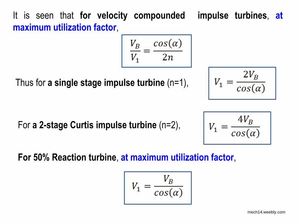
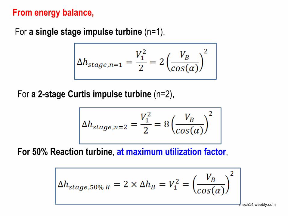
It is seen that for velocity compounded impulse turbines, at
maximum utilization factor,
Thus for a single stage impulse turbine (n=1),
For a 2-stage Curtis impulse turbine (n=2),
For 50% Reaction turbine, at maximum utilization factor,
mech14.weebly.com
From energy balance,
For a 2-stage Curtis impulse turbine (n=2),
For 50% Reaction turbine, at maximum utilization factor,
For a single stage impulse turbine (n=1),
mech14.weebly.com
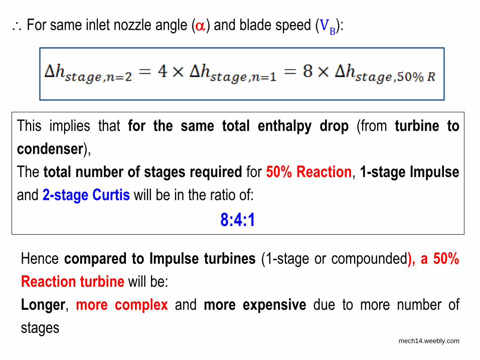
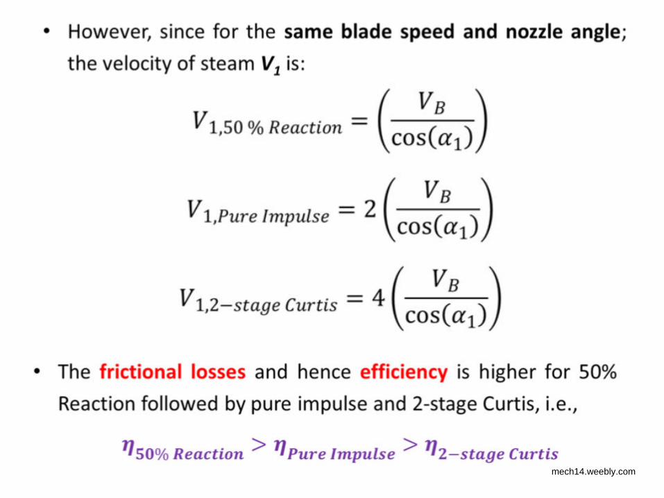
For same inlet nozzle angle () and blade speed (VB):
This implies that for the same total enthalpy drop (from turbine to
condenser),
The total number of stages required for 50% Reaction, 1-stage Impulse
and 2-stage Curtis will be in the ratio of:
8:4:1
Hence compared to Impulse turbines (1-stage or compounded), a 50%
Reaction turbine will be:
Longer, more complex and more expensive due to more number of
stages mech14.weebly.com
mech14.weebly.com

Efficiency vs speed ratio curves for 1-stage impulse turbine & 50% Reaction turbine
mech14.weebly.com
mech14.weebly.com
mech14.weebly.com
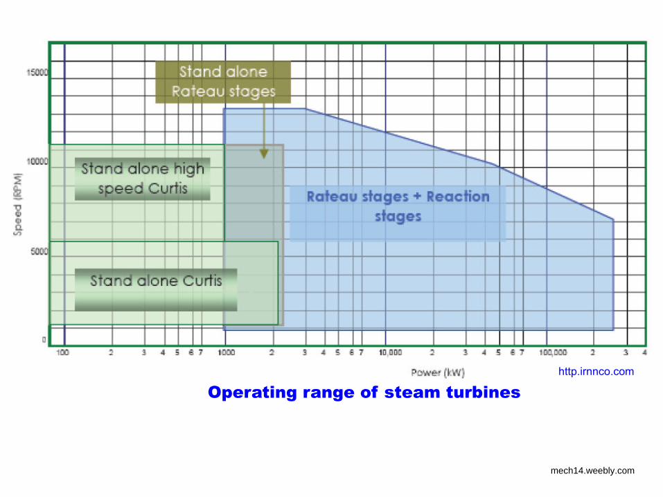
Operating range of steam turbines
http.irnnco.com
mech14.weebly.com
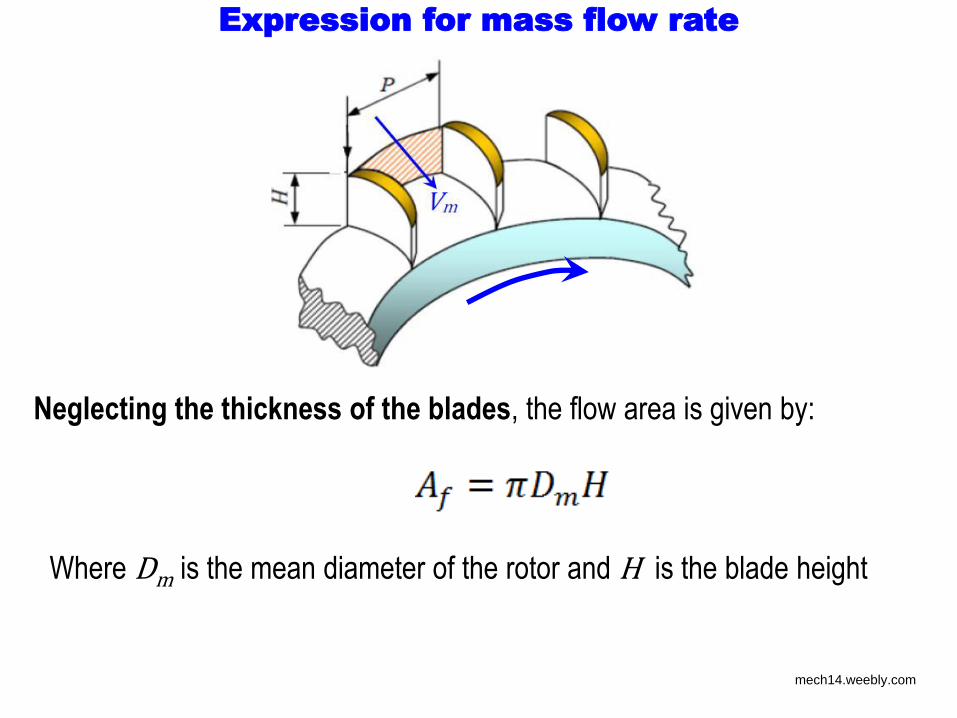
Expression for mass flow rate
Neglecting the thickness of the blades, the flow area is given by:
Where Dm is the mean diameter of the rotor and H is the blade height
mech14.weebly.com
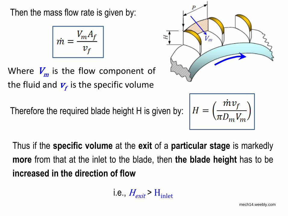
Then the mass flow rate is given by:
Where Vm is the flow component of
the fluid and vf is the specific volume
Thus if the specific volume at the exit of a particular stage is markedly
more from that at the inlet to the blade, then the blade height has to be
increased in the direction of flow
Therefore the required blade height H is given by:
i.e., Hexit > Hinlet
mech14.weebly.com
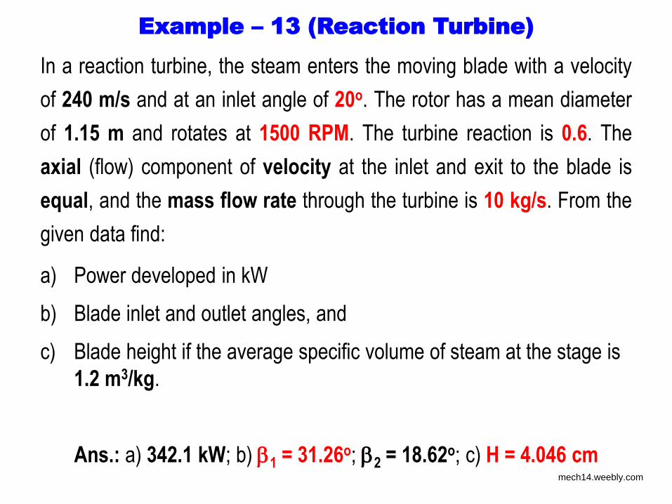
Example – 13 (Reaction Turbine)
In a reaction turbine, the steam enters the moving blade with a velocity
of 240 m/s and at an inlet angle of 20o. The rotor has a mean diameter
of 1.15 m and rotates at 1500 RPM. The turbine reaction is 0.6. The
axial (flow) component of velocity at the inlet and exit to the blade is
equal, and the mass flow rate through the turbine is 10 kg/s. From the
given data find:
a) Power developed in kW
b) Blade inlet and outlet angles, and
c) Blade height if the average specific volume of steam at the stage is
1.2 m3/kg.
Ans.: a) 342.1 kW; b) 1 = 31.26o; 2 = 18.62o; c) H = 4.046 cm
mech14.weebly.com
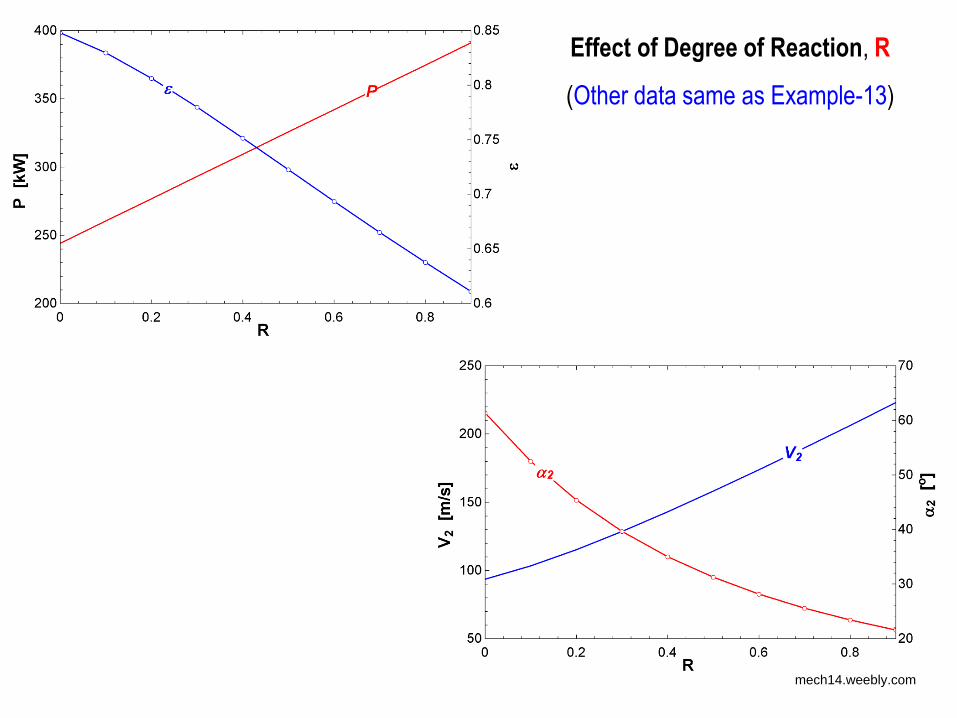
Effect of Degree of Reaction, R
(Other data same as Example-13)
mech14.weebly.com
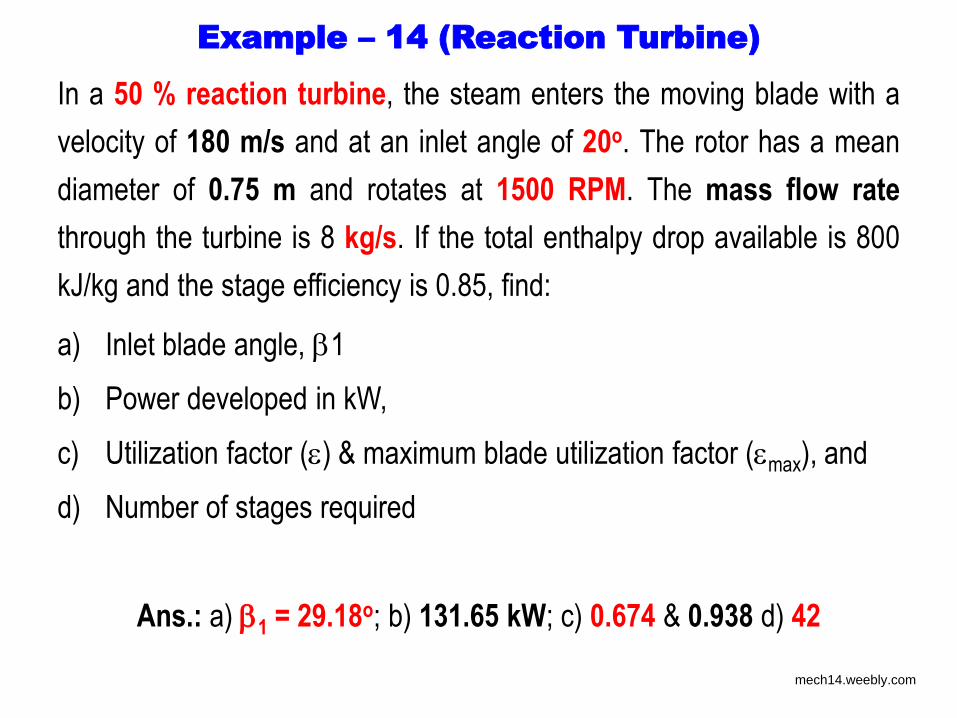
Example – 14 (Reaction Turbine)
In a 50 % reaction turbine, the steam enters the moving blade with a
velocity of 180 m/s and at an inlet angle of 20o. The rotor has a mean
diameter of 0.75 m and rotates at 1500 RPM. The mass flow rate
through the turbine is 8 kg/s. If the total enthalpy drop available is 800
kJ/kg and the stage efficiency is 0.85, find:
a) Inlet blade angle, 1
b) Power developed in kW,
c) Utilization factor () & maximum blade utilization factor (max), and
d) Number of stages required
Ans.: a) 1 = 29.18o; b) 131.65 kW; c) 0.674 & 0.938 d) 42
mech14.weebly.com
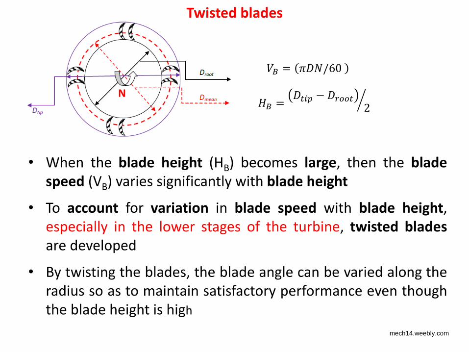
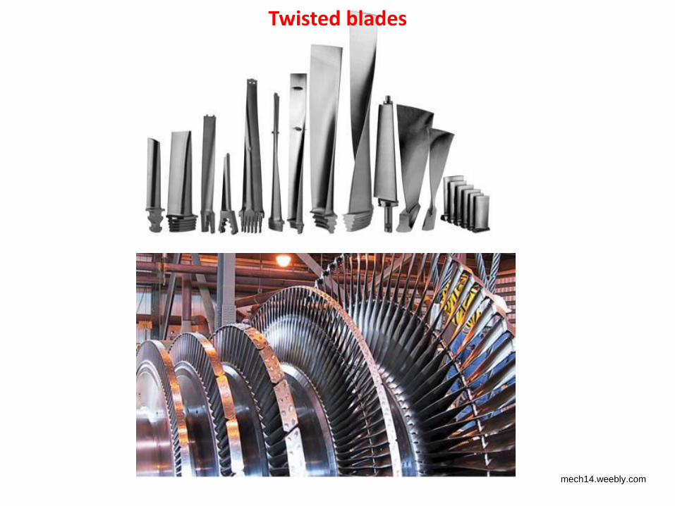
N
• When the blade height (HB) becomes large, then the blade
speed (VB) varies significantly with blade height
• To account for variation in blade speed with blade height,
especially in the lower stages of the turbine, twisted blades
are developed
• By twisting the blades, the blade angle can be varied along the
radius so as to maintain satisfactory performance even though
the blade height is high
𝐵 = 𝜋 𝑁/6
𝐵 = 𝑖 −
Twisted blades
mech14.weebly.com
Twisted blades
mech14.weebly.com
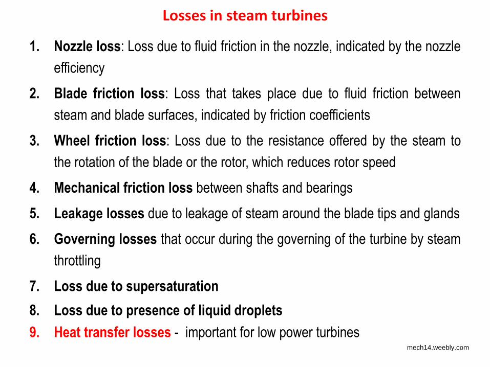
Losses in steam turbines
1. Nozzle loss: Loss due to fluid friction in the nozzle, indicated by the nozzle
efficiency
2. Blade friction loss: Loss that takes place due to fluid friction between
steam and blade surfaces, indicated by friction coefficients
3. Wheel friction loss: Loss due to the resistance offered by the steam to
the rotation of the blade or the rotor, which reduces rotor speed
4. Mechanical friction loss between shafts and bearings
5. Leakage losses due to leakage of steam around the blade tips and glands
6. Governing losses that occur during the governing of the turbine by steam
throttling
7. Loss due to supersaturation
8. Loss due to presence of liquid droplets
9. Heat transfer losses - important for low power turbines mech14.weebly.com
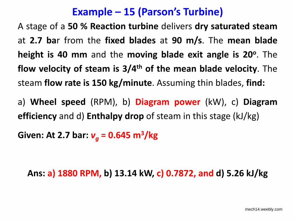
A stage of a 50 % Reaction turbine delivers dry saturated steam
at 2.7 bar from the fixed blades at 90 m/s. The mean blade
height is 40 mm and the moving blade exit angle is 20o. The
flow velocity of steam is 3/4th of the mean blade velocity. The
steam flow rate is 150 kg/minute. Assuming thin blades, find:
a) Wheel speed (RPM), b) Diagram power (kW), c) Diagram
efficiency and d) Enthalpy drop of steam in this stage (kJ/kg)
Given: At 2.7 bar: vg = 0.645 m3/kg
Ans: a) 1880 RPM, b) 13.14 kW, c) 0.7872, and d) 5.26 kJ/kg
Example – 1 Parson’s Turbine
mech14.weebly.com
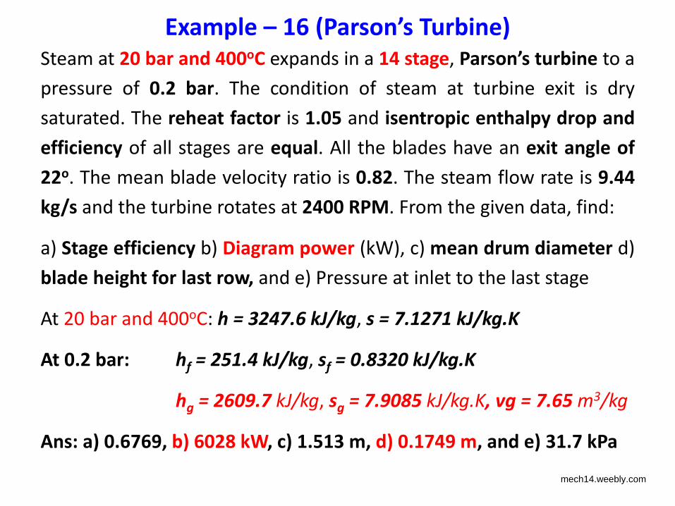
Steam at 20 bar and 400oC expands in a 14 stage, Parson’s turbine to a
pressure of 0.2 bar. The condition of steam at turbine exit is dry
saturated. The reheat factor is 1.05 and isentropic enthalpy drop and
efficiency of all stages are equal. All the blades have an exit angle of
22o. The mean blade velocity ratio is 0.82. The steam flow rate is 9.44
kg/s and the turbine rotates at 2400 RPM. From the given data, find:
a) Stage efficiency b) Diagram power (kW), c) mean drum diameter d)
blade height for last row, and e) Pressure at inlet to the last stage
At 20 bar and 400oC: h = 3247.6 kJ/kg, s = 7.1271 kJ/kg.K
At 0.2 bar: hf = 251.4 kJ/kg, sf = 0.8320 kJ/kg.K
hg = 2609.7 kJ/kg, sg = 7.9085 kJ/kg.K, vg = 7.65 m3/kg
Ans: a) 0.6769, b) 6028 kW, c) 1.513 m, d) 0.1749 m, and e) 31.7 kPa
Example – 1 Parson’s Turbine
mech14.weebly.com
Example – 1 Parson’s Turbine
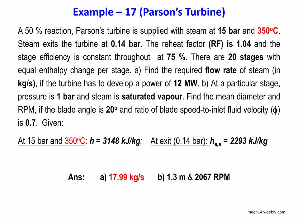
A 50 % reaction, Parson’s turbine is supplied with steam at 15 bar and 350oC.
Steam exits the turbine at 0.14 bar. The reheat factor (RF) is 1.04 and the
stage efficiency is constant throughout at 75 %. There are 20 stages with
equal enthalpy change per stage. a) Find the required flow rate of steam (in
kg/s), if the turbine has to develop a power of 12 MW. b) At a particular stage,
pressure is 1 bar and steam is saturated vapour. Find the mean diameter and
RPM, if the blade angle is 20o and ratio of blade speed-to-inlet fluid velocity ()
is 0.7. Given:
At 15 bar and 350oC: h = 3148 kJ/kg; At exit (0.14 bar): he,s = 2293 kJ/kg
Ans: a) 17.99 kg/s b) 1.3 m & 2067 RPM
mech14.weebly.com
Example – 1 Parson’s Turbine
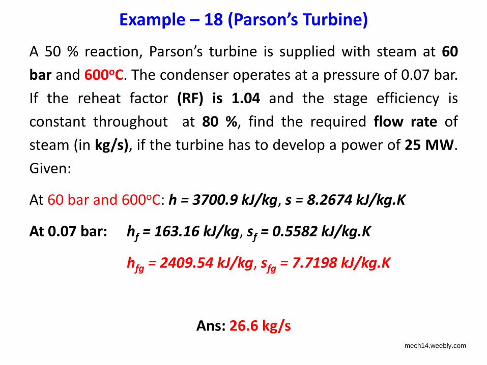
A 50 % reaction, Parson’s turbine is supplied with steam at 60
bar and 600oC. The condenser operates at a pressure of 0.07 bar.
If the reheat factor (RF) is 1.04 and the stage efficiency is
constant throughout at 80 %, find the required flow rate of
steam (in kg/s), if the turbine has to develop a power of 25 MW.
Given:
At 60 bar and 600oC: h = 3700.9 kJ/kg, s = 8.2674 kJ/kg.K
At 0.07 bar: hf = 163.16 kJ/kg, sf = 0.5582 kJ/kg.K
hfg = 2409.54 kJ/kg, sfg = 7.7198 kJ/kg.K
Ans: 26.6 kg/s mech14.weebly.com
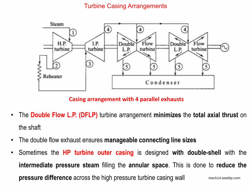
Turbine Casing Arrangements
Casing arrangement with 4 parallel exhausts
• The Double Flow L.P. (DFLP) turbine arrangement minimizes the total axial thrust on
the shaft
• The double flow exhaust ensures manageable connecting line sizes
• Sometimes the HP turbine outer casing is designed with double-shell with the
intermediate pressure steam filling the annular space. This is done to reduce the
pressure difference across the high pressure turbine casing wall mech14.weebly.com
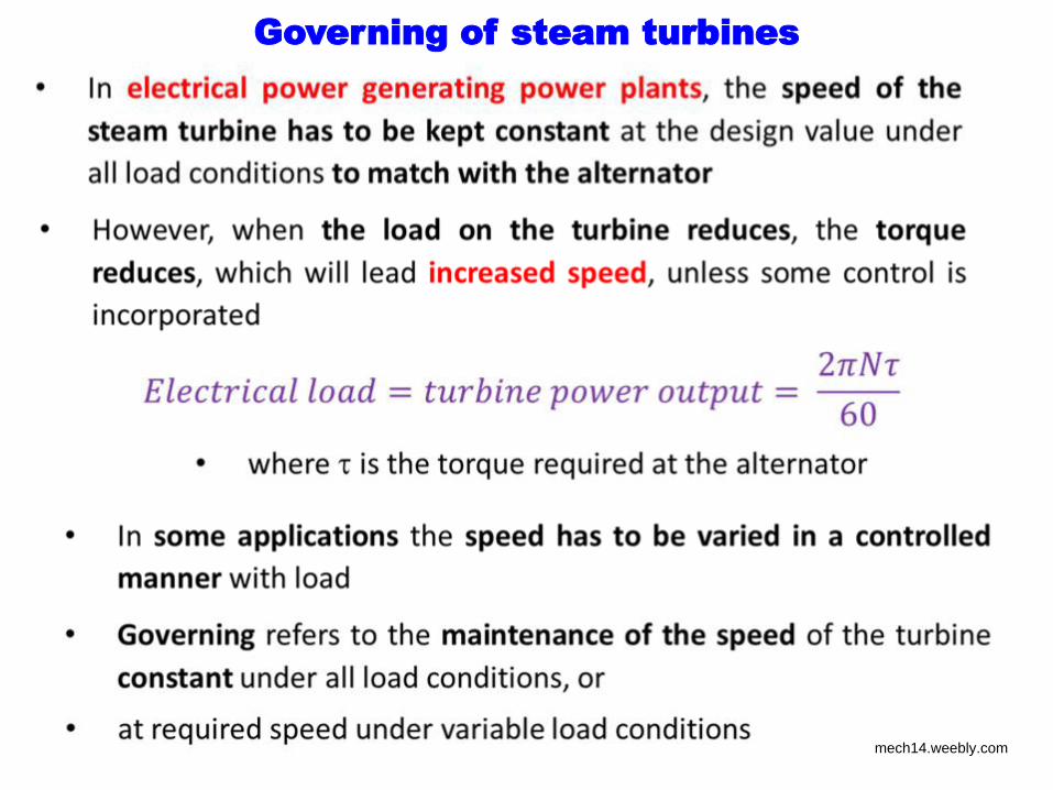
Governing of steam turbines
mech14.weebly.com
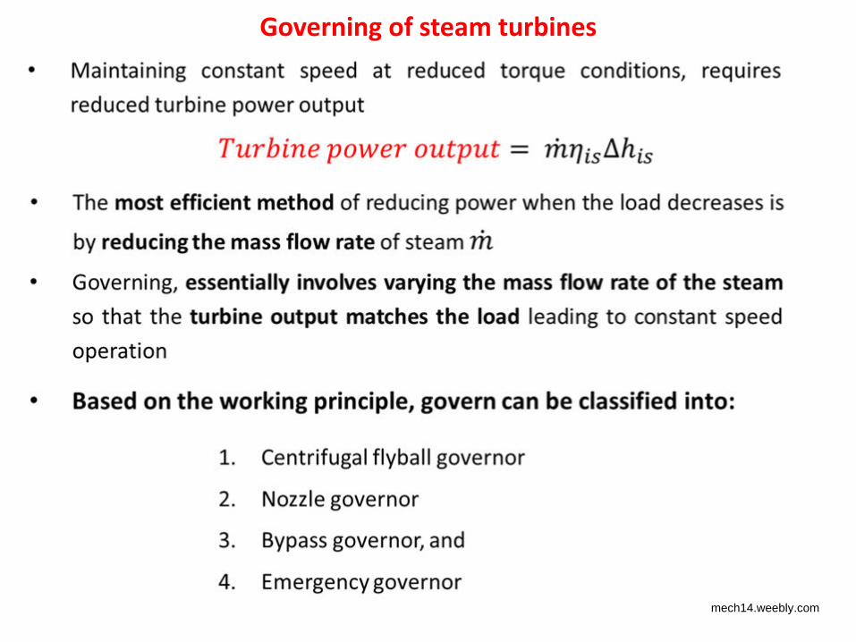
Governing of steam turbines
mech14.weebly.com
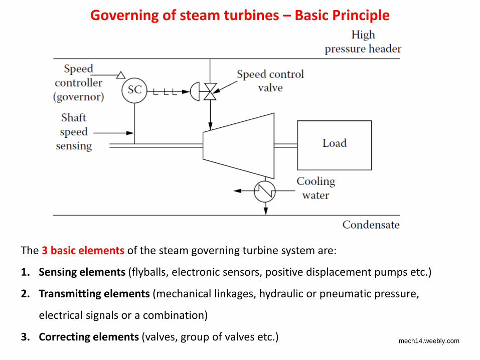
Governing of steam turbines – Basic Principle
The 3 basic elements of the steam governing turbine system are:
1. Sensing elements (flyballs, electronic sensors, positive displacement pumps etc.)
2. Transmitting elements (mechanical linkages, hydraulic or pneumatic pressure,
electrical signals or a combination)
3. Correcting elements (valves, group of valves etc.) mech14.weebly.com
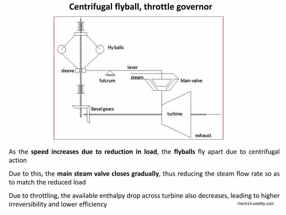
Centrifugal flyball, throttle governor
As the speed increases due to reduction in load, the flyballs fly apart due to centrifugal
action
Due to this, the main steam valve closes gradually, thus reducing the steam flow rate so as
to match the reduced load
Due to throttling, the available enthalpy drop across turbine also decreases, leading to higher
irreversibility and lower efficiency mech14.weebly.com
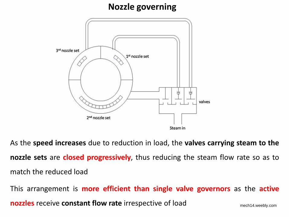
Nozzle governing
As the speed increases due to reduction in load, the valves carrying steam to the
nozzle sets are closed progressively, thus reducing the steam flow rate so as to
match the reduced load
This arrangement is more efficient than single valve governors as the active
nozzles receive constant flow rate irrespective of load mech14.weebly.com
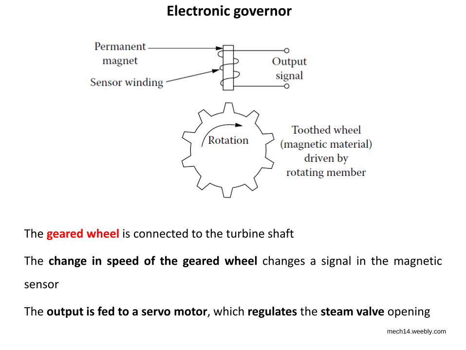
Electronic governor
The geared wheel is connected to the turbine shaft
The change in speed of the geared wheel changes a signal in the magnetic
sensor
The output is fed to a servo motor, which regulates the steam valve opening
mech14.weebly.com
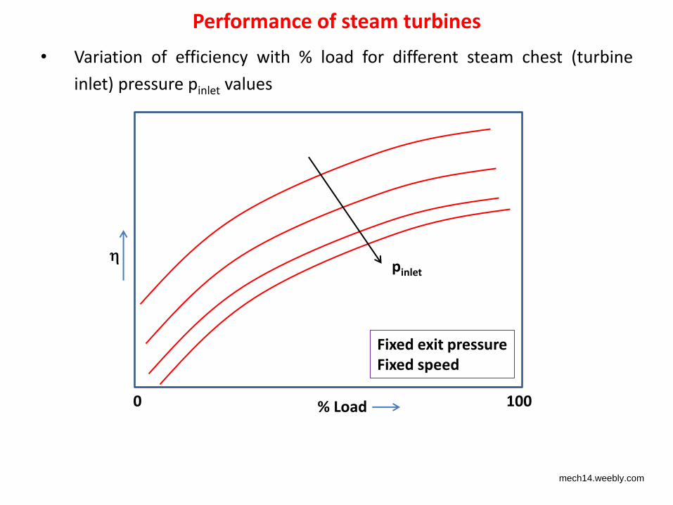
Performance of steam turbines
• Variation of efficiency with % load for different steam chest (turbine
inlet) pressure pinlet values
% Load 0 100
pinlet
Fixed exit pressure
Fixed speed
mech14.weebly.com
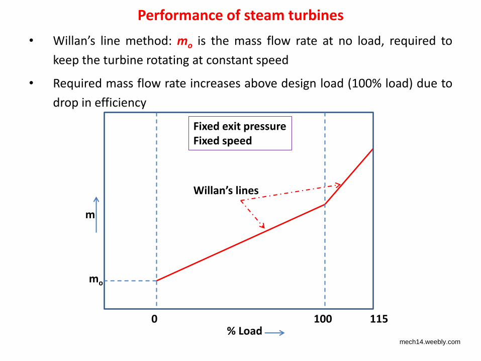
Performance of steam turbines
• Willan’s line method: mo is the mass flow rate at no load, required to
keep the turbine rotating at constant speed
• Required mass flow rate increases above design load (100% load) due to
drop in efficiency
% Load 0 100
m
Fixed exit pressure
Fixed speed
115
mo
Willan’s lines
mech14.weebly.com
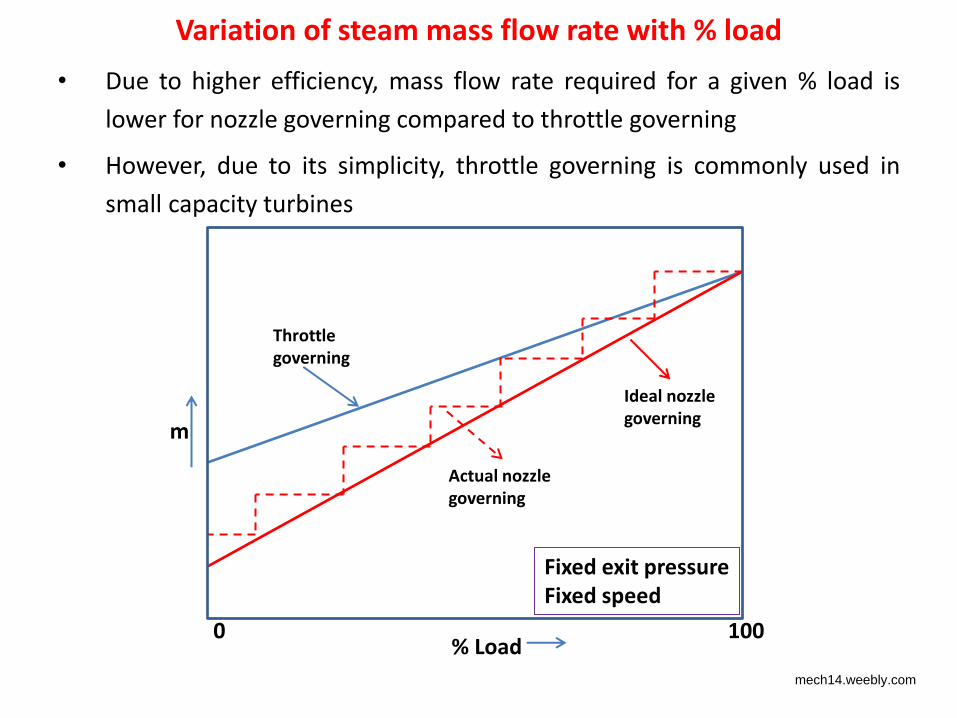
Variation of steam mass flow rate with % load
• Due to higher efficiency, mass flow rate required for a given % load is
lower for nozzle governing compared to throttle governing
• However, due to its simplicity, throttle governing is commonly used in
small capacity turbines
% Load 0 100
m
Fixed exit pressure
Fixed speed
Ideal nozzle
governing
Actual nozzle
governing
Throttle
governing
mech14.weebly.com

End of Module 4
mech14.weebly.com