Embed Size (px)
Citation preview

A Problem zn Large Scale Mapping
B. SHMUTTER,
Civ. lng., Geodesy Division Technion, Haifa
ABSTRACT: This paper describes a method of establishing data for correct positioning of map sheets on the drawing table of the A utograph, when no controlpoints on the sheets are available. The determination of the data is done numerically, and is at the same time part of the procedure of the absolute orientation(scaling). The solution is arranged for the Autograph A7.
1. PLACEMENT OF SHEETS ONDRAWING TABLE
I N LARGE-SCALE mapping (1:500, 1:1,000)it often happens that the map of the area
presented by one model, covers several sheets.The control points which serve the absoluteorientation are usually located at the edges ofthe model. Thus on each sheet of the mapthere is at the most one control point. Theproblem then arises how to adjust the sheeton the drawing table of the Autograph.
Establishing the data with which to placethe sheets correctly on the drawing table isbest performed by a transformation of coordinates. From these data the grid intersections which define the corners of the singlesheets are determined in the reference systemof the Autograph. Having computed themachine coordinates of these corners, thex, y carriages of the Autograph are moveduntil the corresponding readings appear onthe x, y counters and the sheet is positioned inaccordance with these grid intersections onthe drawing table. An essential condition forthe solution is that the counters must be keptunchanged during the whole orientation andmapping procedure.
Although the required data may be obtained in a general way, and the desiredmachine coordinates computed before themodel is levelled, it is advisable to arrangethe solution into separate stages, and to determine the corners of the single sheets in thesystem of the Autograph only after the levelling has been performed. The reasons for thisare:
a-The model has to be mapped and thelevelling must be done in any case.
b-The control points for levelling themodel may be distinct from those onwhich the scaling is done.
c-Separating the levelling saves computational work and simplifies the problemconsiderably.
Therefore it is supposed in the followingthat the model has been levelled and alsoapproximately scaled.
As stated above, the determination of thegrid intersections follows from a coordinatetransformation. But this transformation iscarried out in a model whose projection basehas not yet assumed its proper length. Underthese circumstances the only useful information derivable from the coefficients of transformation is the required base correction.From this correction the final model scale isestablished.
After changing the length of the projectionsbase the model points on the projection planeare displaced. This may suggest the need for asecond coordinate transformation. Howevertwo coordinate transformations would undoubtedly complicate the solution and makeit ineffective. Therefore an attempt will bemade to avoid the second transformation andto make use of the data already obtained fromthe first one.
The geometrical nature of the scale-changeis a similitude transformation. Thus thereshould be a point-the centre of similitudewhich remains fixed (in the projection plane)while the other points move. If the origin ofthe reference system of the projection plane istranslated to the centre of similitude, thenafter the coordinate transformation and theadjustment of the base, it becomes possible torelate the required coordinates in the newscale to this constant origin. The centre ofsimilitude is defined in the Autograph A7 bythe coordinates x = 500, y = 500, where x andyare given on the scales attached to therespective carriages.
In what follows it is supposed that allmeasurements are carried out in a systemwhose origin coincides with the above definedpoint.
145
146 PHOTOGRAMMETRIC ENGINEERING
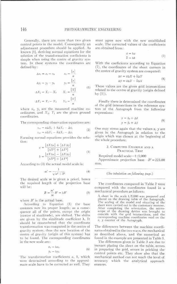
Generally, there are more than two givencontrol points in the model. Consequently anadjustment procedure should be applied. Asknown [1], deriving normal equations for thesolution of the transformation coefficients issimple \I-hen using the centre of gravity system_ In these systems the coordinates aredefined by:
must agree now with the new establishedscale. The corrected values of the coefficientsare obtained from:
These values are the given grid intersectionsrelated to the centre of gravity (origin definedby (1».
(7)
(8)
a ="Aab = Ab
With the coefficients according to Equation(7), the coordinates of the sheet corners Inthe centre of gravity system are computed:
t.x = iit!.X+bt.Y
t.y=iit!.Y-bt.x
(1 )
[x]Xo=
n[y]
Yo =-n
[X]Xo =-
n
t.Yi = Yi - Yo
t.Xi = Xi - X o
The corresponding observation equations are:
Forming normal equations provides the solution:
where Xi, Yi are the measut-ed machine coordinates, and Xi, Yi are the given groundcoordinates.
Vxi = at.Xi + bt. Yo - t.Xi
Vyi = al1 Yo.: - b.t1.tYi - I1Yi
(9)x=io+t.x
)' = Yo + t.y
One may stress again that the values X, yaregiven in the Autograph in relation to theorigin which was chosen at the beginning ofthe whole procedure.
Finally there is determined the coordinatesof the grid in tersections in the reference system of the Autograph from the followinj!expressions:
(2)
[y]Yo =-
nt.Yi = Yi - Yo
[:'Xt.x] + [t.l"t.y]a = [t.X2] + [t.Y2]
b = [t.Yt.x] - [t.Xt.y][t.X 2
] + [t.Pj
According to (3) the actual model scale is:
(3)
2. COMPUTED EXAMPLE AKD A
PRACTICAL TEST
Required model scale-1 :5,000Approximate projection base-B' = 223.00
mm.
The coordinates computed in Table 2 werecompared with the coordinates found in amechanical procedure as follows:
A sheet in the scale 1/5,000 was prepared andplaced on the drawing table of the Autograph.The scaling of the model and situating of thesheet were carried out in the customary manner.After completing the orientation, the microscope of the drawing device was brought tocoincide with the grid intersections, and thecorresponding machine coordinates read on thex, y counter of the Autograph.
(See tabulation on f oliowing page.)
The differences between the machine coordinates obtained in the two ways, the mechanicalas described above, and the numerical asfound in the example are presented in Table 3.
The differences given in Table 3 are due toinexact placing the sheet on the table, errorsin preparing the grid, errors in pricking thecontrol points etc. They show also that themechanical method can not reach the level ofaccuracy which the analytical approachensures.
(4)
(5)
(6)
1JL'
1n'B = -B' = "AB'
111
va2 +b2
The desired scale m is given a priori, hencethe required length of the projectior. basewill be:
where B' is the actual base.According to Equation (5) the base
assumes now its proper length; as a consequence all of the points, except the origin(centre of similitude), are shifted. The shiftsare given by the similitude coefficient X. Itshould be remembered that the coordinatetransformation was computed in the centre ofgravity system; thus the new location of thecentre of gravity (origin of this system) hasto be found. The corresponding coordinatesin the new scale are:
xo = "Axo
Yo = "Ayo
The transformation coefficients a, b, whichwere determined according to the approximate scale have to be corrected as well. They

A PROBLEM IN LARGE SCALE MAPPING
TABLE 1
CONTROL POINTS OF THE MODEL
Measured Machine Coordinates Gillen Ground Coordinates
Point xmm ymm 4Y 1JL Ym
1009 - 71.43 -146.33 75 147.3 105 921.71010 109.31 -209.82 75377.2 106 857.2995 - 63.99 211.90 73 346.8 105 790.2996 169.33 151.67 73537.9 106 988.2831 61.95 29.14 74 202.8 106 508.2
SOLUTION OF THE TRANSFORMATlON
a= 0.19784131~From Equation (3)
b = -0.0186006)m' = 5036.3 -Actual model scale. From Equation (4)
:\=1.006472-Similitude coefficient. From Equation (5)B=:\B'=224.44 mm-Required base. From Equation (5)Xo = :\xo =41. 30 mml
~ -The centre of gravity in thc required scale. From Equatioll (6)Yo =:\)'0 = 7.26 111m)x =41.30 -0 .0187210t.X+0 . 1991218L'. YI Transformation equations in thc required scale.
~ From Equation (7) (9).y= 7 .26-0.1991218L'.X -0.01872IO':>Y)
TABLE 2
THE COORDINATES OF THE REQt:lRED GRID h"TEI(SFCTlO:--lS
147
Alap systemRelated to centre of gravity C01llputed machine
Pointof control points coordinates
Xm Ym Xm Ym xmm yn/11l
1 73,5000 106,000.0 -822.4 -413.1 -25.56 178.752 73,500.0 J07,000.0 -822.4 586.9 173.56 160.033 75,000.0 106,000.0 677 .6 -413.1 -53.64 -119.934 75,000.0 107,000.0 677 .6 586.9 145.58 -138.65
3. SUMMARY
The proposed solution makes possiblcdetermining analytically the corners of thesingle sheets in the coordinate system of theAutograph. These values are introduced without observing any points in the model, andwithout involving any height measurementsfor adj usting the map sheets.
Point
1234
TARLE 3
..,r 11l'1U
+0.02-0.03-0.19-0.10
ymm
-0.10+0.08
, +0.02+0.18
The choice of the similitude centre as anorigin of the reference system in which thecoordinates of the model points are measured,makes possible using the transformationcoefficients obtained in the approximate scale,for the determination of data in the requiredscale.
The analytical treatment of the problemincreases the accuracy of the absolute orienta-
db= -0.03 11lm.
tion (scaling), and makes possible the bestcompilat(on of the single sheets in one map.
REFERENCE
I. Hallert B., licber die Hcrstellung Photogrammctrischer Plaenc, Stockholm, 194-1.