Embed Size (px)
Citation preview

The Pennsylvania State University
The Graduate School
College of Engineering
A PROCESS MODEL FOR HEATING, VENTILATING AND AIR
CONDITIONING SYSTEMS DESIGN FOR ADVANCED
ENERGY RETROFIT PROJECTS
A Thesis in
Architectural Engineering
by
Yifan Liu
© 2012 Yifan Liu
Submitted in Partial Fulfillment
of the Requirements
for the Degree of
Master of Science
December 2012

ii
The thesis of Yifan Liu was reviewed and approved* by the following:
John I. Messner
Professor of Architectural Engineering
Thesis Co-Adviser
Robert M. Leicht
Assistant Professor of Architectural Engineering
Thesis Co-Adviser
Chimay J. Anumba
Professor of Architectural Engineering
Head of the Department of Architectural Engineering
*Signatures are on file in the Graduate School.

iii
Abstract
Buildings consume approximately 40% of the total energy in the United States. The urgent need
to improve energy efficiency in buildings has been widely recognized. To enable the design of
more energy efficient buildings, digital analysis and simulation tools can be implemented into
more integrated design processes. A challenge to the successful implementation of an integrated
design process supported by digital tools is the clear definition of the processes and information
exchanges points in the process.
To address this problem, this research defines a design process model for Heating, Ventilating,
and Air Conditioning (HVAC) systems for energy retrofit projects. The final process model
contains key activities in the retrofit project HVAC system design process that can be
implemented in the integrated design and delivery approach, and identifies key information
requirements and outputs for different activities. The model was developed and validated
through literature analysis, interviews, focus group discussions, and case studies.
This process model can serve as a reference for project teams to collaboratively identify key
information exchanges in the process used on a project, thereby allowing the team to clearly
define the content of the exchanges. The process model can also support decisions which are
required as the design team plans the overall process for design execution. Finally, the process
model identifies important information exchanges which should be more clearly documented
through industry standards.

iv
Table of Contents
List of Figures .............................................................................................................................. viii
List of Tables .................................................................................................................................. x
1. Introduction .............................................................................................................................. 1
1.1. Background ................................................................................................................ 1
1.2. Research Questions .................................................................................................... 4
1.3. Goal and Objectives ................................................................................................... 5
1.4. Reader’s Guide........................................................................................................... 5
2. Research Methodology ............................................................................................................ 6
2.1. Key Research Steps.................................................................................................... 6
2.2. Research Techniques ................................................................................................. 7
2.2.1. Literature Review....................................................................................................... 7
2.2.2. Case Studies ............................................................................................................... 7
2.2.3. Focus Group Discussion ............................................................................................ 8
2.2.4. Interviews ................................................................................................................... 9
2.2.5. Content Analysis ...................................................................................................... 11
2.3. Research Stages ....................................................................................................... 12
2.3.1. Background Study and Process Map Development Stage ....................................... 12
2.3.2. Process Map Validation and Improvement Stage .................................................... 12

v
2.3.3. Research Process Map ............................................................................................. 14
3. Literature Review................................................................................................................... 16
3.1. The Significance of Process Modeling / Mapping ................................................... 16
3.2. The Existing Design Process Models ...................................................................... 17
3.2.1. The Generic Design and Construction Process Protocol ......................................... 18
3.2.2. The RIBA Plan of Work for Design Team Operation ............................................. 19
3.2.3. The Integrated Building Process Model (IBPM) and the Integrated Design Process
Model (IDPM) ...................................................................................................................... 20
3.2.4. An Information Delivery Manual for the HVAC Design process ........................... 23
3.2.5. Integrative Design Process Described by the Integrative Design Guide ................. 24
3.2.6. Engineering Design Process Models ....................................................................... 25
3.2.7. Common Characteristics of the Design Models ...................................................... 27
3.3. The Significance of a Design Process Model .......................................................... 28
3.4. Process Mapping Techniques .................................................................................. 28
3.4.1. Flow Charts .............................................................................................................. 28
3.4.2. Data Flow Diagram .................................................................................................. 29
3.4.3. Control Flow Diagram ............................................................................................. 30
3.4.4. IDEF ......................................................................................................................... 30
3.4.5. Business Process Modeling Notation (BPMN) and Its Advantages ........................ 31
3.5. HVAC Systems Architecture ................................................................................... 33

vi
3.6. Integrated Design Phasing ....................................................................................... 35
4. Process Model Development ................................................................................................. 38
4.1. Design Phasing......................................................................................................... 38
4.2. Process Model Components ..................................................................................... 40
4.3. Process Map Context, Principles and Assumptions ................................................. 46
4.4. Foundation and Framework of the Process Model .................................................. 48
4.5. Creating the Initial Process Model ........................................................................... 50
5. Process Map Validation and Improvement ............................................................................ 60
5.1. Stage Overview ........................................................................................................ 60
5.2. Case Studies ............................................................................................................. 61
5.3. Design Process Expert Workshop Discussions........................................................ 66
5.3.1. Workshop Overview ................................................................................................ 66
5.3.2. Workshop Design and Setup .................................................................................... 67
5.4. Data analysis and Process Map Cross Comparison ................................................. 72
5.5. Integrated Feature Enhancement.............................................................................. 78
5.6. Further Validation through Interviews and Process Comparison ............................ 79
5.6.1. Process Validation through Interviews .................................................................... 79
5.6.2. Process Map Comparison ........................................................................................ 80
6. The Integrated HVAC Design Process Model ....................................................................... 81

vii
7. Conclusion ............................................................................................................................. 84
7.1. Research Summary .................................................................................................. 84
7.2. Contributions............................................................................................................ 85
7.2.1. Contribution to Process Modeling ........................................................................... 85
7.2.2. Contribution to Integrated Design ........................................................................... 86
7.2.3. Contribution to the National Building Information Model Standard (NBIMS) Effort
86
7.3. Limitations and Future Research ............................................................................. 87
Reference ...................................................................................................................................... 89
Appendix A: Integrated HVAC System Design Process Model .................................................. 95
Appendix B: Process Model Description .................................................................................... 111
Appendix C: Case Study and Workshop Maps........................................................................... 127

viii
List of Figures
Figure 1: Energy Consumption by Sectors (Rodgers 2009) ........................................................... 1
Figure 2: Building Gross Energy Intensity, 1979-2003 .................................................................. 2
Figure 3: Typical Office Building Energy Consumption by End Use (National Action Plan for
Energy Efficiency 2008) ................................................................................................................. 3
Figure 4: Electricity Consumption by End Use for All Buildings (CBECS 2008) ........................ 4
Figure 5 Research Process Map .................................................................................................... 15
Figure 6: The Generic Design and Construction Process Protocol Level II (Wu et al. 2001) ...... 19
Figure 7: RIBA Plan of Work Diagram 1: Outline Plan of the Work (RIBA 1973) .................... 20
Figure 8: The Integrated Building Process Model (Sanvido et al. 1990) ..................................... 21
Figure 9: IDPM Node Tree (Sanvido and Norton 1994) .............................................................. 22
Figure 10: The High Level HVAC Design Process (Wix 2006) .................................................. 24
Figure 11: Part of the process map for the integrative design process(7group and Reed 2009) .. 25
Figure 12: Total Design Activity model ( Pugh 1986) ................................................................. 26
Figure 13: Total Design Activity Model for Building (Pugh 1986) ............................................. 27
Figure 14: The Conceptual and Schematic Data Flow Model (Baldwin et al. 1999) ................... 30
Figure 15: Schematic Presentation of Function Box (Material Laboratory 1981) ....................... 31
Figure 16 Pool and Lanes of the Integrated HVAC Design Process Model ................................. 41
Figure 17 Events ........................................................................................................................... 42
Figure 18 Collapsed Sub-Process, Expanded Sub-Process, and Atomic Task ............................. 43
Figure 19 Information Objects ...................................................................................................... 44
Figure 20 Connectors .................................................................................................................... 45

ix
Figure 21 Annotation .................................................................................................................... 46
Figure 22 IBPM level 3 Serves as a Framework for the HVAC Process Development ............... 50
Figure 23 Process Map Developed From Interview ..................................................................... 56
Figure 24 Programming Phase of the Preliminary HVAC Design Process Model ...................... 57
Figure 25 Programming Phase of the Initial Integrated HVAC Design Process Model .............. 59
Figure 26 HVAC Designer Coordinates with Electrical Engineer in the Mechanical Room of IST
....................................................................................................................................................... 64
Figure 27 Design Drawings Collected from the Case Study Project ............................................ 65
Figure 28 Setup of the Workshop Discussion............................................................................... 67
Figure 29 Map Developed for Schematic Design Phase .............................................................. 69
Figure 30 Map from SD phase Process Rearranging Activity ...................................................... 70
Figure 31 Sticky Note Process Map of DD and CD phase ........................................................... 70
Figure 32 The Process Map Developed from Workshops with OPP............................................ 72
Figure 33 Documentation of Workshop Activities ....................................................................... 74
Figure 34 Process Maps Used for Cross Comparison .................................................................. 76
Figure 35 Change Log and Map after Cross Comparison ............................................................ 77
Figure 36 Discovery Phase of the Integrated HVAC Process Model ........................................... 82
Figure 37 Activity Description ..................................................................................................... 83

x
List of Tables
Table 1 UNIFORMAT II HVAC Systems Breakdown (Charette et al. 1999) ............................. 34
Table 2 Design Phasing Table ...................................................................................................... 39
Table 3 Phasing Comparison of Integrated HVAC Design Process and Traditional Process ...... 40
Table 4 Gateways .......................................................................................................................... 44
Table 5 Case Study Projects with OPP ......................................................................................... 62
Table 6 Overview of Workshop Discussions................................................................................ 67
Table 7 Process Model Statistics .................................................................................................. 85

1
1. Introduction
1.1. Background
According to U.S. Department of Energy (2009), energy consumption from commercial and
residential buildings accounts for approximately 39% of the total energy consumption in the
United States (see Figure 1). In addition, the energy consumption of the building industry
remained almost constant through the past thirty years, while the energy efficient of the other
industry sectors has significantly decreased as shown in Figure 2. As energy conservation and
efficiency have long been a commonly acknowledged need across the U.S, and become even
more popular concepts recently, to improve building energy efficiency has become an urgent
challenge facing the building industry.
Figure 1 Energy Consumption by Sectors (Rodgers 2009)

2
Figure 2 Building Gross Energy Intensity, 1979-2003
One of the causes for building energy inefficiency is due to older building systems and a
limitation in the integration in the building system design. Current design tasks are frequently
performed in isolation and do not involve all impacted stakeholders in a timely fashion, which
leads to the missing of many synergistic opportunities that can help improve building energy
efficiency. On the contrary, the integrated design approach aims to fully utilize and synergize the
professional knowledge of all related parties. Though isolated successful integrated design
practices exist, it still remains a challenge for design teams to perform the integrated design
efficiently and effectively. Hence, there is a need to understand and clearly define the integrated
design process.
In addition to the benefit of guiding the design team, understanding the integrated design process
helps project teams identify better ways to integrate digital design and analysis tools into the
design process (Computer Integrated Construction Research Program 2010). The process model
generated throughout this research can help with the National Building Information Model
Standard (NBIMS) by serving as a big picture map for the coordination of the Information
Delivery Manual (IDM) development.

3
HVAC systems are critical to building energy efficiency. According to U.S. Environmental
Protection Agency (EPA) (2008), HVAC systems consume 55% of the energy in a typical office
building (see Figure 3). The Commercial Buildings Energy Consumption Survey (CBECS) by
U.S. Energy Information Administration shows that HVAC systems consume 33% of the
electricity in a building (see Figure 4). As integrated design process includes the sub-processes
of system design, it is important to focus on the building HVAC systems design process because
of its critical role to the building energy efficiency. In addition, consider the low volume of new
building projects, it is obvious that in order to improve building energy efficiency, a lot of work
needs to be done in terms of retrofitting buildings (Petersdorff et al. 2006).
Figure 3 Typical Office Building Energy Consumption by End Use (National Action Plan for Energy
Efficiency 2008)

4
Figure 4 Electricity Consumption by End Use for All Buildings (CBECS 2008)
1.2. Research Questions
This research focused on addressing the following questions:
What is the process used to design retrofit project HVAC systems in an integrated design
environment?
What information flows within the activities in the integrated HVAC design process?
What information should be exchanged to parties outside of the integrated HVAC design
process?
What are the integrated design features that should be added into the traditional design
process to increase the integration level of the design process?

5
1.3. Goal and Objectives
This research aims to develop a process model that describes an energy retrofit Heating
Ventilating, and Air Conditioning (HVAC) systems design process for implementation in an
integrated delivery approach.
To achieve this goal, the following objectives were pursued:
Develop process maps for the traditional HVAC design process of retrofit projects;
Identify information inputs and outputs of the HVAC design tasks;
Refine the process model for implementation in the integrated design process; and
Validate the process maps through interviews, workshop discussions, and case studies.
1.4. Reader’s Guide
This section gives readers a guide to the chapters of this thesis. Chapter 2 introduces the research
methodologies chosen for this research and the detailed research process. Chapter 3 reviews
literature about process mapping, previous building process models, process modeling
techniques/notations, and the project phasing methods. Chapter 4 describes the first stage of the
thesis research, which was to develop an initial process model based on literature. Chapter 5
describes the process of validating and improving the initial process model through case studies,
workshop discussions, interviews, and further literature content analysis. Chapter 6 introduces
the structure of the process maps and how to read the process maps and process description.
Samples of the process maps and a description are presented. Chapter 7 concludes this thesis
with the contributions of this research, the research limitations and future research directions.

6
2. Research Methodology
This chapter introduces the research methodologies chosen for this research, the reasons they
were chosen, and how each methodology was implemented. Research stages and processes are
described. A research process map is created to illustrate the organization of the research process.
2.1. Key Research Steps
This research began with a literature review on previous process models, integrated design
guides and building HVAC system design guides. Several interviews were conducted to collect
more HVAC system specific process information. An initial set of process maps were developed
from the literature review and interview activities. With the purpose of validating and improving
the initial process maps, a series of workshop discussions were held with several experienced
HVAC designers and two case studies were conducted on two small retrofit projects. Based on
the validated process maps, further process enhancements were made based on integrated design
principles. The enhanced process model was validated again through interviews with
experienced HVAC designers in an AE firm, and through cross comparison against another
independent HVAC design process model.
Research methods used include:
1. Literature review;
2. Semi-structured interviews;
3. Case studies, workshop discussions and interviews; and
4. Content analysis.

7
2.2. Research Techniques
2.2.1. Literature Review
An extensive literature review forms the basis of this research. The literature review was focused
on understanding the previous effort and status on process mapping research and collect related
process data from the previous literature. Major process models in building industry, integrated
design guide, and HVAC design guide were thoroughly reviewed, analyzed, and compared. The
literature review showed that the Integrated Building Process Model (IBPM) (Sanvido et al. 1990)
was the most appropriate process model to serve as a foundation and framework of the HVAC
system process model development. The reasons are the following three: first, the IBPM has
gone through intense validation processes and are relatively more rigorous; second, IBPM
describes generic and high level process which allows enough space and flexibility for the
detailed, system specific process model development; third, though IBPM was developed based
on projects with traditional delivery method, it contains many design integration mechanism,
which suits the need of the this research for more integrated design process.
2.2.2. Case Studies
Case study research is used to describe an entity that forms a single unit such as a person, an
organization or an institution (Hancock 1998). Compared to other research methods, case studies
can offer richer and deeper contextual information. Case study methods are also highly versatile
and can employ other data collection methods from testing to interviewing. A case study can
have different levels of complexity (Hancock 1998). A simple case study can be an illustrative

8
description of a single event or occurrence. A more complex case study can be an analysis of a
situation over a period of time.
In case studies, observation can be conducted in a structured or unstructured manner (Pretzlik
1994). Unstructured observation is commonly used in anthropological and sociological research,
while structured observation is extensively used in psychology (Mulhall 2003). Unstructured
observation was used in this research based on the above categorization.
Unstructured observation, according to Mulhall (2003), provides insight into the interaction
between individuals and groups. It also illustrates the big picture and the context of the process.
By recording the context in which people work, observation captures the primary social setting.
In this thesis research, two case studies were performed by tracking the progress of two small
size HVAC system retrofit projects on The Pennsylvania State University campus at University
Park. Through observing the case studies, process maps as well as process descriptions for each
case study project was developed. The maps and descriptions were then analyzed and compared.
2.2.3. Focus Group Discussion
Focus group discussion is a method of interviewing a group of people. In focus group discussion,
the interviewer creates a supportive environment and asks focused questions to encourage
discussion and the expression of differing opinions and perspectives. The focus group method
assumes that people need to listen to other’s opinions and ideas to form and facilitate their own.
The questions in a focus group discussion are usually very simple in order to promote the
participants’ expression of their views (Marshall and Rossman 1999).

9
The advantages of focus-group interviews are that the participants are interviewed in a more
natural and relaxed atmosphere than a one-to-one interview, plus the brainstorm effect of hearing
opinions from other participants, more accurate and higher quality data could be collected. The
focus group discussion also gives the facilitator the flexibility to explore unanticipated issues as
they arise in the discussion. The cost of focus groups is relatively low and they can provide quick
results (Marshall and Rossman 1999).
This data collection method was used to validate and improve the process. A series of focus
group meetings were conducted with the HVAC designers in the Office of Physical Plant (OPP)
at The Pennsylvania State University to discuss the HVAC design process in different phases.
Knowing that the success of focus group discussions depends on the skill of the facilitator, the
researcher invited people who are experienced and skilled in conducting interviews and focus
groups to join the focus group meeting to facilitate the discussion. All focus groups were audio
recorded and transcribed afterwards.
2.2.4. Interviews
According to Polit and Hungler (1998), an interview is a data collection method in which an
interviewer asks the respondent questions, either in person or by telephone. Interviews are an
effective data collection method in that the ambiguity of the questions that lead to interviewees
misunderstanding can be clarified during the interview, so the interviewers can ensure the quality
of the data collected.
Disadvantages of interviews are also documented in the literature (Hancock 1998). It is time
consuming and in some situations expensive to conduct and transcribe the interviews. The data
quality generated from the interview depends largely on the interviewers’ expertise. However,

10
these are necessary costs related to the interview and the impact on the research results can be
controlled.
There have been a variety of categorizations of qualitative interviews (DiCicco-Bloom and
Crabtree 2006). A common categorization divides interviews as structured, semi-structured,
unstructured and group interview.
In a structured interview, the interviewer prepares a script beforehand and strictly follows the
same script in each interview (Myers and Newman 2007). The interviewees may be asked close
ended questions and asked to choose from the provided answers. This type of interviews is
usually taken when the researcher cannot attend the interview.
In an unstructured interview, the interviewer does not prepare a plan or question list for the
interview. He or she discusses with the interviewee the topics of interest and questions are
framed based on the previous answers of the interviewee (Hancock 1998). Usually the
unstructured interviews can cover topics in great detail, but results are heavily dependent on the
interviewer’s skill and knowledge.
Semi-structured interviews are the most widely used interview format (DiCicco-Bloom and
Crabtree 2006). They are usually scheduled in advance at a designated time and location. The
semi-structured interview typically proceeds with open ended questions that are either
predetermined or merging from the dialogue in the interview. They can be conducted with an
individual or group and typically last from half an hour to several hours.
Interviews were mainly used as a validation method in this research. Semi-structured individual
in-depth interviews were conducted after the series of workshop discussions to validate the

11
process maps developed from the workshop discussions. Interviews were also conducted as a
second round of validation with experienced industry HVAC designers. By using open ended
questions, semi-structured interviews encourage interviewees to freely expand on their
experience, which was valuable to this research. Marshall and Rossman (1999) point out that
the way we speak is different from how we write. For instance, we don’t speak in paragraphs,
nor do we signal punctuation when speaking. We also lose the visual cues that we rely on to
interpret the interviewee’s meaning. Fully aware of the above mentioned difference, the
researcher transcribed the interview audio recording in a timely manner following the interview
to ensure that transcript correctly captured the content of the interview.
2.2.5. Content Analysis
Content analysis, as defined by Krippendorff (2004), is a research technique that researchers use
to draw valid and replicable reference from the collected data to the context of their use. The
content analysis method varies depending on the nature and goal of the research. Content
analysis was extensively used in this research to organize, analyze, and summarize the
information collected through literature review, interviews, workshop discussion and case studies.
The content analysis of literature was performed through developing tables and process maps
from the narratives and cross comparing the process maps from different literature. The data
collected from case studies, workshops and interviews are compiled in several text documents,
which were analyzed line by line. Important or useful data was identified and commented.
Several process maps were developed from the analyzed data, which, along with other data
collected from workshops and case studies, were used to validate and improve the initial maps
developed from literature.

12
2.3. Research Stages
This research can be divided into two stages, which were: 1) the background study and process
map development stage, and 2) the process map validation and improvement stage. The
following two sections provide an overview of the two stages. More detailed information for
each stage can be found respectively in Chapter 4 and Chapter 5.
2.3.1. Background Study and Process Map Development Stage
This stage started with an extensive literature review of previous building process models and
process mapping techniques. Literature review shows that previous research has mapped the
building process from various perspectives. However, previous process modeling efforts focused
on high level generic building processes and rarely focused on a specific building system.
Therefore a process model development strategy was created for the researcher to combine the
generic process model data with the logic of HVAC system design. Based on the strategy, the
researcher extracted data from various process models and HVAC design guides and started
developing a preliminary set of process models. Along with the literature review and analysis,
several interviews and discussions were conducted with faculties, designers and graduate
students in Penn State Architectural Engineering Department who have experience in the HVAC
design and construction process. The preliminary process model was revised several times based
on the comments and feedbacks from the interviews and discussions.
2.3.2. Process Map Validation and Improvement Stage
The initial process maps were developed based on data collected from literature analysis and
interviews. The process of integrating data from various sources involved personal judgments
and decisions of the researcher. Therefore it was necessary to validate the initial process maps

13
using data collected from other independent sources which involved no subjective interference
from the researcher. Besides the need for independent validation, the initial process maps
represented the HVAC design process of new building projects rather than retrofit projects. This
was caused by a lack of literature describing retrofit project design processes. The initial process
maps also lacked clarity and details when describing certain parts of the process. Hence more
detailed, retrofit project specific data was needed to make the process model retrofit focused and
more comprehensive. In response to the process validation and improvement needs, the
researcher designed a series of workshop activities with experienced HVAC designers from Penn
State’s Office of Physical Plant (OPP) to collect more data. Six workshops were conducted over
six consecutive weeks which included an iterative process mapping task and focus group
discussions of the maps developed in previous weeks. During the workshop activities, a process
model of the typical design process of the HVAC systems was developed. Detailed data about
the interactions among HVAC designers and other design participants were also collected.
Besides the workshop activities, the researcher conducted two case studies on two on going
small retrofit projects at the Penn State University Park campus. By going to meetings and field
visits with the designers and tracking their progress throughout the design projects, the
researcher developed two process maps for the design process of the two retrofit projects.
With the data collected from workshops and case studies, the researcher started detailed content
analysis by analyzing the narrative documentations of the workshops and case studies. Useful
information was identified and commented. Process maps developed from the different methods
and the data from the content analysis were compared.
After finishing the validation of the process maps with data collected from OPP, the researcher
conducted two semi-structured interviews with experienced HVAC designers in a large
14
engineering company. Data collected from the interviews were used for a second round of
process model validation. Through these validation processes, the initial process maps developed
from literature and interviews were validated and improved through adding detail and providing
a retrofit focus.
2.3.3. Research Process Map
The primary process for implementing the research process is illustrated through the process map
in Figure 5, which is created using Business Process Management Notation.

15
Figure 5 Research Process Map

16
3. Literature Review
3.1. The Significance of Process Modeling / Mapping
A process is “a series of activities (task, steps, events, operations) that takes an input, adds value
to it, and produces an output (product, service, or information) for a customer” (Anjard 1998).
An effective and efficient process is necessary for maintaining a company’s competitive
advantage and exceeding customer expectations.
A process map is a visual aid for understanding the abstract work processes. It shows how the
tasks, inputs and outputs are linked (Anjard 1998). A process model in this thesis means a
hierarchical set of process maps, with a detailed explanation for each map. Process mapping /
modeling can identify the start and end events in a business process, information exchanges
between activities and decisions made in the business process (Karlshøj 2011). A graphical
model of a process can accelerate the understanding of the process. In addition, with a process
model, inefficient activities can be quickly identified. Just as the activities that cannot be
measured cannot be managed, the activities that cannot be clearly identified, analyzed and linked
together cannot be challenged, and thus cannot be improved and perfected (Womack 2003).
According to Kaneta et al. (1999), there are several principles of an effective process model. The
first principle is that a process model should have a good visibility of the process so that the
process participants can easily recognize his or her role by looking at the process model. The
second principle is that the relationships and dependency among activities are classified to
support proper management effort. The third principle is that a process participant should be able
to understand other participants who have activities with information flows to their activities.

17
Browning (2002) pointed out several uses of a good process model:
Program Execution: A process model helps determine what to work on next, evaluate
progress, coordinate deliverables, and analyze the impacts of changes and the value of
options.
Baseline for Continuous Improvement: A process model can help analyze potential
process changes in terms of net value (investment costs vs. value added benefits) and
helps isolate root causes of problems.
Knowledge Retention and Learning: A process model can facilitate the capture of lessons
learned when the process does not work as expected. The process model can also serve as
a basis for common vocabularies for the activities, deliverables, and interactions.
Process Visualization: A process model helps people visualize where they are in a
process and what they need and must produce and when. It provides the basis for focused,
committed, and accountable collaboration between organizations, teams, individuals, and
even companies.
Training: A process model can help new hires get oriented, see what they need to do and
why, and see where to go for more information.
3.2. The Existing Design Process Models
Design in the context of facility construction is a process in which a facility owner’s needs are
defined, quantified, documented and communicated to the builders (Sanvido et al. 1990).
Different researchers and groups have developed many design process models or whole building

18
process models that include the design phase. This section introduces existing process models
which focus on or include elements of the design process.
3.2.1. The Generic Design and Construction Process Protocol
One of the well-known process models for facility design and construction is the Generic Design
and Construction Process Protocol (GDCPP), also called as the process protocol. This process
model was developed at the University of Salford in 1998. The model maps the entire facility
project lifecycle and aims to allow a wide range of parties to work together seamlessly by
providing a common set of definitions, documentation and procedures (Kagioglou et al. 1998).
The GDCPP model learns from the best practices of the manufacturing industry. It incorporates
principles such as stakeholder involvement, design stage gate approach, teamwork and feedback.
The GDCPP also reconstructs the project team by activity zones rather than in disciplines with
the purpose of creating a cross-functional team (Wu et al. 2001). Breaking the GDCPP into more
detail, the GDCPP Level 2 was developed, which includes sub process maps of eight activity
zones (see Figure 6).

19
Figure 6 The Generic Design and Construction Process Protocol Level II (Wu et al. 2001)
3.2.2. The RIBA Plan of Work for Design Team Operation
Another widely used building design process model is the RIBA Plan of Work for Design Team
Operation, which was first issued as a section of the RIBA Handbook in 1964. The intention of
this Plan of Work is to provide a process model for the systematic working of the design team.
The RIBA plan of work describes the outline of a work plan and represents a logical sequence of
action that has to be taken to make good decisions at the right time. The RIBA Plan of Work
assumes that the architect is the leader and manager of the design who will be responsible for the
information and professional skills availability, the good communication, and making sure
everyone understands their responsibility and so on (RIBA 1973). Figure 7 shows the first

20
diagram of the RIBA Plan of Work, which shows the general outlines for the design stages.
Figure 7 RIBA Plan of Work Diagram 1: Outline Plan of the Work (RIBA 1973)
3.2.3. The Integrated Building Process Model (IBPM) and the Integrated Design Process
Model (IDPM)
Developed by the Penn State Computer Integrated Construction (CIC) Research Program, the
Integrated Building Process Model (IBPM) is a generic, integrated process model of essential
activities and functions required to provide a facility and maintain the facility over its lifecycle
(Sanvido et al. 1990). Based on the Integrated Definition for Function Modeling (IDEF0) method,
the IBPM can be broken down to five levels of details, with the highest level of the IBPM

21
describing the five major functions in the lifecycle of a facility: Plan Facility, Design Facility,
Construct Facility, Operate Facility, and Manage Facility. Plan Facility consists of all the
functions required to define the owner’s needs and methods to achieve these. Design Facility
consists of all functions required to define and communicate the owner’s needs to the builder.
Construct Facility consists of all the functions required to assemble a facility so that the facility
can be operated. Operate Facility consists of all the functions required to provide the end user
with an operational facility. This process model was validated through case study analysis of 22
projects, and is the culmination of work from several interrelated studies of the various phases of
a project lifecycle. The IBPM is one of the most extensive process models of the facility delivery
process. Figure 8 shows the five functions at the highest level of the IBPM.
Figure 8 The Integrated Building Process Model (Sanvido et al. 1990)

22
Sanvido et al. (1990), Chung (1989), and Lapinski et al. (2005) point out several limitation of the
IBPM. The process elements of the IBPM are abstract, which makes the process flow difficult to
understand. The execution mechanisms of the functions depend on the delivery method, which is
not considered in IBPM.
Developed by Sanvido and Norton (1994), the Integrated Design Process Model (IDPM)
improves upon the “Design Facility” phase of the IBPM by expanding the boundary of the model
to include four major activities. The first activity is paying better attention to the marketing and
contracting functions of the company. The second activity is to conduct better formal planning of
the design activities. The third activity is to provide a more focused prequalification and
background check on the designers and contractors, and analyze the available resources and
information. The fourth activity is to perform detailed and thorough review of the design and
documentation to minimize errors and omissions before the release of the design document.
Figure 9 shows the IDPM node tree.
Figure 9 IDPM Node Tree (Sanvido and Norton 1994)

23
3.2.4. An Information Delivery Manual for the HVAC Design process
As part of the buildingSMART International initiatives to develop information standards, an
Information Delivery Manual (IDM) aims to serve as the integrated reference for process and
data required to perform a process and define the exchange requirements. An IDM approaches its
goal by identifying the discrete business processes within defined scope of the IDM, the
information for their execution and the results of that activity (Wix 2007). An IDM consists of
three main components: Process Map (PM), Exchange Requirements (ER) and Functional Parts
(FP). The process maps of an IDM can cover a wide range of processes in the building lifecycle,
including the HVAC systems design process. Figure 10 shows the high level of an IDM that was
developed to depict the HVAC design process. Note that this IDM is the only process map that
could be identified to illustrate the details of the HVAC design process. There is no
documentation of the specific methodology used to develop or validate the process used within
the IDM, and there is currently no further documentation regarding the current use or adoption of
this process map.

24
Figure 10 The High Level HVAC Design Process (Wix 2006)
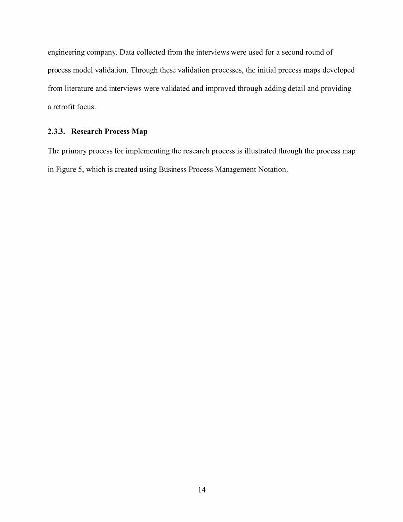
3.2.5. Integrative Design Process Described by the Integrative Design Guide
Developed by 7group and Reed (2009), “The Integrative Design Guide for Green Building” is a
practical book that provides a whole building approach to green building. Green building design
principles and philosophies are introduced with detailed and typical stories in the integrative
design. The book also provides a detailed guide to how to conduct integrative design to generate
better green buildings. The process described by the book follows an integrative design pattern,
which is an iteration of workshops and research/analysis. Although named as design guide, the
book covers the lifecycle of a project from the discovery phase of a project, which is the early
planning and concept development phase, to the construction and maintenance of a project.
Figure 11 shows a snapshot of part of the process map recreated by the researcher in Business
Process Mapping Notation (BPMN) format.
25
Figure 11 Part of the process map for the integrative design process(7group and Reed 2009)
3.2.6. Engineering Design Process Models
Process reengineering and improvement has long been a focus of the manufacturing sector
(Kagioglou et al. 2000). Hence many design models can be found in the engineering design
realm. One of the best known models is Pugh’s total design model (Pugh 1986). The total design
activity model can describe the process of any product, including buildings, from the defining of
the need for the product to the sale of the product (see Figure 12).

26
Figure 12 Total Design Activity model ( Pugh 1986)
As an example of the total design activity model, Pugh (1986) provided a building design
process model (see Figure 13). The main part of the total design model is called the “design
core”, which in the building process case, consists of user group, brief, concept, detail, construct,
and sell. The circle of arrows that envelopes the design core is called the product design
specification (PDS), the specification of the product to be designed. The PDS controls the total
design activities, as it places boundaries on the subsequent designs (Pugh 1990). The outer
columns of the model are different parties involving in the design. The parties will use their
knowledge and techniques to input information to the design core.
While the total design model provides an interesting overall framework for the engineering
design process and gives principles for the design, it does not specifically describe the building
design process.

27
Figure 13 Total Design Activity Model for Building (Pugh 1986)
Other than the total design model, two additional well-known models of engineering design are
the VDI model of engineering design and the design model developed by Pahl (2007).
3.2.7. Common Characteristics of the Design Models
Besides the models introduced in the previous section, other design process models includes the
model of the concept and scheme design stages of a project developed by Baldwin et al. (1995),
the model of civil and structural engineering elements of the design stage developed by Austin
et al. (1996), and the integrated process model developed by Kaneta et al. (1999). The common
characteristic of previous mentioned design process model is that they give a pretty good
overview of the design process by describing the high level stages within the design process.
However, they do not decompose the process into detailed levels and they contain very little

28
detail information. This makes it difficult to use them in managing detailed design processes
(Pektas and Pultar 2006).
3.3. The Significance of a Design Process Model
Design is a process in which owner’s needs are defined, quantified, documented and
communicated to the builders. It is a project phase where many critical decisions are made.
These decisions commit a lot of resources. Therefore, the decision makers need adequate and
accurate information in a timely manner. Currently inaccurate, incomplete, or untimely
information causes various problems in the design. Design caused waste is the largest category
of time waste in a project (Rounce 1998). Therefore, design process models aim to capture the
complexities of the design processes and facilitate the process improvement (Pektas and Pultar
2006). Developing a model of the design process is beneficial for defining the information needs,
flows, and uses (Sanvido and Norton 1994).
3.4. Process Mapping Techniques
There are many process modeling methods/techniques. This section provides a general
introduction to several process modeling methods with a specific focus on Business Process
Modeling Notation (BPMN), IDEF techniques, and Data Flow Diagrams, which are the more
appropriate tools for modeling the building design process.
3.4.1. Flow Charts
Flow charts were first used by programmers to describe the logic or path of execution within an
executing program. Flow charts were developed to model the logic within a single process

29
(Dufresne and Martin 2003). Hence they are not suitable to model interactions between multiple
processes, simultaneous activity sequences, and dependent processes (Lapinski 2005).
3.4.2. Data Flow Diagram
Developed by De Marco (1979) to assist software system specification, Data Flow Diagram
(DFD) is a popular diagrammatic modeling method and system analysis tool that concentrates on
the data flow in an information system. The model depicts a system as a network of processes,
data stores, and source/sink, which are interconnected by data or information flows (Chung
1989). The DFDs are structured in a way that is easy to create, understand, and validate.
However, the DFDs cannot describe the process sequencing or process control mechanisms
(Dufresne and Martin 2003). Research has shown that DFD is a helpful and manageable way to
model the building design process. Many characteristics have made the DFD technique an
appropriate tool to model the design process, which is a system consisting of processes or tasks
linked by interfaces. Three of the most important characteristics are: (1) DFDs are naturally
hierarchical; (2) DFDs will not be impacted by how the processes are performed; (3) DFDs
views systems from an information perspective (Austin et al. 1994). Figure 14 is a sample DFD
for conceptual and schematic design.

30
Figure 14 The Conceptual and Schematic Data Flow Model (Baldwin et al. 1999)
3.4.3. Control Flow Diagram
Control Flow Diagrams (CFD) are similar to DFDs except that they are more appropriate in
event-driven situations versus data-driven situations (Dufresne and Martin 2003).
3.4.4. IDEF
Developed in the 1970s for the US aerospace industry, IDEF is probably the most commonly
used traditional business process modeling technique. There are many types of IDEF models,
which allow processes to be described from different points of view. Among those various types
of IDEFs, the IDEF0 is one of the most widely used in design and construction process modeling
(Austin et al. 1999, Karlshøj 2011). IDEF0 models the functions of a process, which receive
inputs, process them with certain mechanisms and under certain controls, and then produce
outputs to feed into other functions. Each function can be subdivided on a separate map to ensure

31
that each level is not too crowded. As IDEF0 describes a process from the perspective of
information, it is an appropriate technique for design process modeling. Austin et al. (1999)
identifies several common features of IDEF0 and DFD, which are: (1) both of them are capable
of top-down analysis, which allows the readers to obtain an overview first and drill into detailed
levels when more information is needed; (2) both of them are easy to read because of their
graphical nature; (3) both of them are a manageable size because of their flexibility in hierarchy;
(4) both of them represent a system from a viewpoint of data; (5) both of them can model
iterative activities; (6) both of them do not show how a task should be performed, but what
information is needed to perform the tasks; and (7) both of them do not represent the temporal
sequence of activities, though they appear to be so. Figure 15 shows a schematic presentation of
a function box in IDEF0 Notation.
Figure 15 Schematic Presentation of Function Box (Material Laboratory 1981)
3.4.5. Business Process Modeling Notation (BPMN) and Its Advantages
The Business Process Modeling Notation (BPMN) is a relatively new modeling notation that is
rapidly gaining acceptance in the business modeling community. BPMN bridges the gap between
business process design and process implementation. BPMN is developed by the Business
Process Modeling Initiative (BPMI) Notation Working Group (now a part of the Object

32
Management Group), with group members accounting for a large segment of the business
process modeling community. In order to absorb the best ideas from various modeling tools and
notations, expertise and experience from many existing notations were brought together when
developing BPMN. Hence the development of BPMN is an important effort to reduce the
fragmentation of the process modeling tools and notations (White 2004). There are mainly four
types of element in BPMN, which are actors, processes, connections and artifacts (IDM technical
Team 2007). Though IDEF0 is most widely used in building process modeling so far, the newly
developed BPMN is still chosen for this research because BPMN can be superior to IDEF0 for
the following reasons:
BPMN is better in its capability to express business process, whereas IDEF0 cannot
represent sequential relationship between activities. Moreover, BPMN can easily and
clearly express and visualize the interactions between different parties, which IDEF0
cannot do easily (Karlshøj 2011);
Several tools ranging from free tools like TIBCO and simple tools like Microsoft Visio,
to extensively complex tools like the IBM Rational Software Architect are available for
modeling in BPMN. Considering the graphical effect, ease of use, and the flexibility of
adjusting modeling, the Microsoft Visio was chosen as the modeling software in this
research; and
BPMN can be conversed to the Business Process Execution Language for Web Services,
which is an emerging standard XML based approach for workflow control (Dufresne and
Martin 2003).
33
3.5. HVAC Systems Architecture
UNIFORMAT was originally developed in 1972 by the General Services Administration (GSA)
and the American Institute of Architects (AIA). In 1993, the enhanced and more comprehensive
UNIFORMAT II was issued by American Society for Testing and Materials (ASTM).
UNIFORMAT II is a classification framework that breaks down the building into elements and
components. UNIFORMAT II as an elemental classification is needed in the design stage in that
it helps with the economic evaluation of building alternatives. UNIFORMAT II can also be used
for cost estimation and analysis, and specification development (Charette et al. 1999).
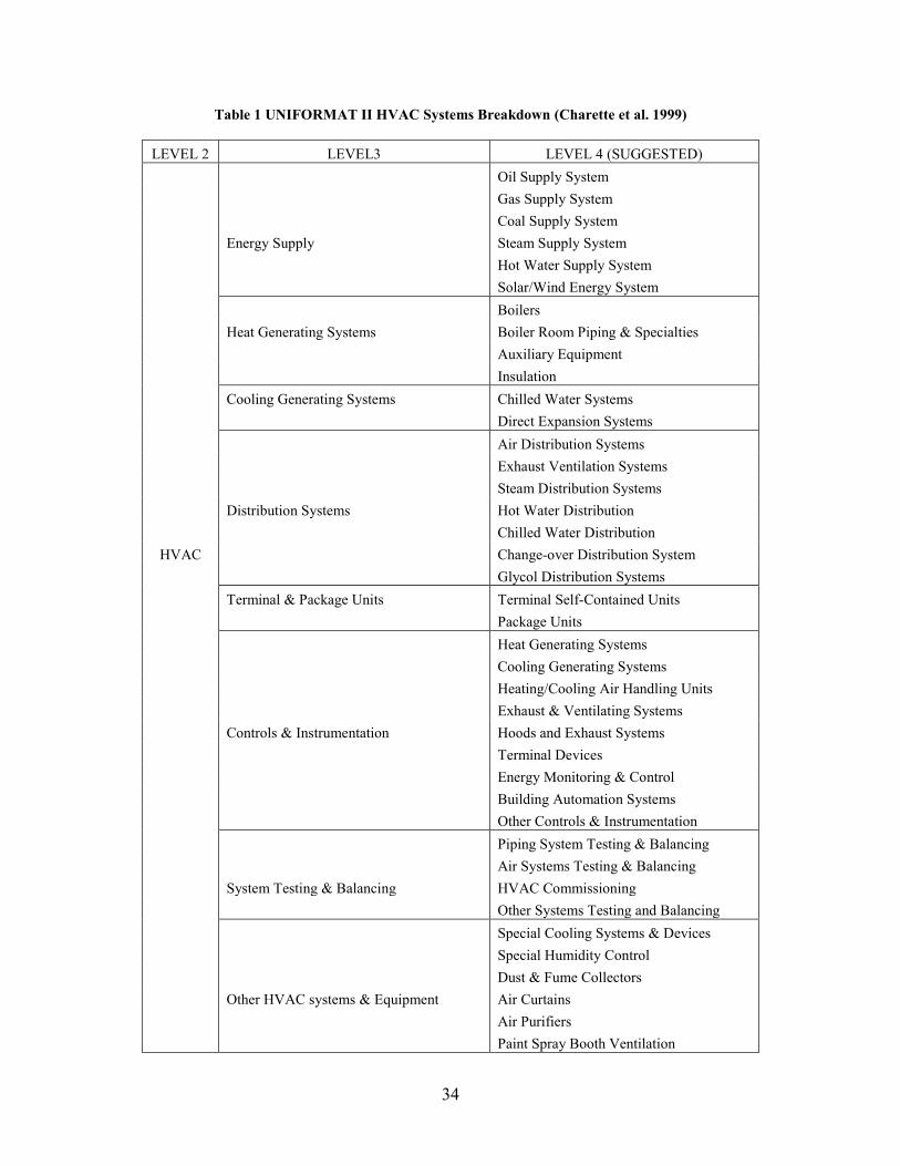
Knowledge of the building HVAC systems breakdown is helpful to a deeper understanding of
the HVAC system. Hence the researcher uses part of the 1997 UNIFORMAT II standard
classification of elements as HVAC systems architecture (see Table 1). This HVAC systems
architecture served as a reference during the process map workshops. This aided the researcher
to have a big picture of how the design is progressing.
34
Table 1 UNIFORMAT II HVAC Systems Breakdown (Charette et al. 1999)
LEVEL 2 LEVEL3 LEVEL 4 (SUGGESTED)
Oil Supply System
Gas Supply System
Coal Supply System
Energy Supply Steam Supply System
Hot Water Supply System
Solar/Wind Energy System
Boilers
Heat Generating Systems Boiler Room Piping & Specialties
Auxiliary Equipment
Insulation
Cooling Generating Systems Chilled Water Systems
Direct Expansion Systems
Air Distribution Systems
Exhaust Ventilation Systems
Steam Distribution Systems
Distribution Systems Hot Water Distribution
Chilled Water Distribution
HVAC Change-over Distribution System
Glycol Distribution Systems
Terminal & Package Units Terminal Self-Contained Units
Package Units
Heat Generating Systems
Cooling Generating Systems
Heating/Cooling Air Handling Units
Exhaust & Ventilating Systems
Controls & Instrumentation Hoods and Exhaust Systems
Terminal Devices
Energy Monitoring & Control
Building Automation Systems
Other Controls & Instrumentation
Piping System Testing & Balancing
Air Systems Testing & Balancing
System Testing & Balancing HVAC Commissioning
Other Systems Testing and Balancing
Special Cooling Systems & Devices
Special Humidity Control
Dust & Fume Collectors
Other HVAC systems & Equipment Air Curtains
Air Purifiers
Paint Spray Booth Ventilation

35
3.6. Integrated Design Phasing
The integrated design process is different from the traditional design process in many ways. One
difference is the division and definition of the design phases. 7group and Reed (2009) have
proposed a revised design phasing method, which emphasizes and expands the early conceptual
phase. American Institute of Architects (2007) also defines an integrated phasing for the design
in their Integrated Project Delivery (IPD) Guide. This section reviews the various design phasing
definitions for integrated design.
The Integrated Building Lifecycle Model developed by Sanvido et al. (1990) divides the design
process into six sub-functions, which are “Understand Functional Requirements”, “Explore
Concepts”, “Develop Systems Schematics”, “Develop Design”, “Communicate Design to
Others”, “Maintain Design Information and Models”. The last sub-function is not a design phase,
but an auxiliary function throughout the design process that serves as a design information
database. In the “Understand Functional Requirements” phase, the information related to the
project is acquired, processed and synthesized. Designers need to gather adequate information
from outside sources, such as the owner, users, regulatory agencies, municipalities and so on.
In the “Explore Concepts” phase, designers will explore general ideas or concepts concerning
initial layout of the building, and other general design requirements. The design in this phase is
vague and multiple concepts and alternatives are explored, such as site use, building systems and
materials. At the end of this phase, every option should be evaluated and typically only one will
be selected for further exploration.
In the “Develop Systems Schematics” phase, the feasible concepts from the last phase are refined
and developed into system schemas. The different system schemes are coordinated, and
evaluated in an integrated fashion.

36
In the “Develop Design” phase, detailed design and the design of major components start.
System level designs are studied using simulations. The overall design will be reviewed and
checked, and preliminary specification, drawings, and schedules will be developed. Final
approval of the design will be granted at the end of this phase.
In the “Communicate Design to Others” phase, the post-design documents, e.g. contract
documents and construction drawings and specs, are developed, reviewed, and delivered for final
approval.
In the “Integrated Project Delivery Guide” developed by AIA, an integrated design process is
divided into “Conceptualization”, which is expanded programming, “Criteria Design”, which is
expanded schematic design, “Detailed Design”, which is expanded design development, and
“Implementation Documents”, which corresponds to a construction documents phase.
In the conceptualization phase, the design team determines what is to be built, who will build it
and how it will be built. In the criteria design phase, the design team starts to design overall
shape, scope and building systems, major design options are explored, evaluated, tested and
selected. In the detailed design phase, all the key design decisions are finalized. The building is
fully and clearly defined, coordinated, and validated and specifications are completed. In the
implementation documents phase, the design drawings stop and shop drawing process starts.
Construction means and methods, cost, and schedule are determined.
As a summary, through the literature review, the researcher has the following findings:
1) There are several foundational lifecycle process maps, but they do not contain a sufficient
level of detail to clearly define the HVAC process model.

37
2) There is one HVAC process model defined within an IDM, but the development and
validation of this process is unclear and there is currently no further documentation regarding
the current use or adoption of this process map.
3) More recent efforts are focused on the impact of greater degrees of integration in the process,
and therefore, it is important to have a detailed process definition to investigate the impact of
integration on the HVAC process.

38
4. Process Model Development
This chapter introduces the background knowledge of the process model and the detailed process
of the development of the initial process model through literature reviews and interviews.
4.1. Design Phasing
Traditionally, the design process has been divided into four phases: Programming phase,
schematic design phase, design development phase, and construction documents phase. In the
traditional HVAC design process, as HVAC designers are dependent on information from
architects and other engineers, a more significant amount of work is done in the later phases of
the design, especially construction documents phase. This can cause delays in the HVAC design
and costly changes late in the process.
To facilitate the concept exploration in the early design phase, it is beneficial to redefine the
work scope of the design phases and adopt a new approach to the phasing of the design process,
which fits the features of the integrated design process. Integrated design requires a different
process flow from traditional design, which is to push design decisions upstream as far as
possible because they are less costly and have more impact in the early phase of design. In
addition, integrated design involves contractors and other stakeholders early in the process and
leverages digital tools more intensely (American Institute of Architects 2007). The Integrated
Project Delivery Guide (IPD Guide) developed by the American Institute of Architects (2007)
provides a redefinition of design phases for integrated design, which considers the above features
of the integrated design process. The integrated HVAC design process model developed in this
research adopts the integrated design phasing defined in the IPD guide, and improves the IPD
phasing based on several other process models and guides, such as the IBPM, integrative design
guide and AHRAE energy efficient design guide. Table 2 lists several different phasing methods

39
from literature and the phasing division of the integrated HVAC design process model. Some
phases have different titles in different literature sources, yet they are in the same row since they
carry similar definitions and scope. For instance, in Row 5 of the table, “Develop Systems
Schematics”, “Criteria Design” and “Schematic Design” all refer to developing and evaluating
major system options. Some phases expand across two columns, which means that a certain
phase’s work scope is equal to the combination of more than one phase in another phasing
definition. For instance, the “Detailed Design” phase defined in the “IPD Guide” covers the work
scope of traditional design development phase plus a major part of the construction documents
phase, the “Implementation Document” phase in the “IPD Guide” covers part of the work scope
of the traditional construction documents plus shop drawing development.
Table 2 Design Phasing Table
STAGE IBPM IPD GuideIntegrative
Design GuideTraditional
Integrated
HVAC Design
Model
Understand
Functional
Requirements
Programming Discovery
Explore
ConceptsN/A Conceptualization
Develop Systems
SchematicsCriteria Stage
Schematic
Design
Schematic
DesignCriteria Stage
Develop DesignDesign
Development
Design
Development
Shop Drawings Shop Drawings Shop
(Owner's
Activity)
Communicate
Design to Others
N/A
Discovery
(Predesign)
Plan N/A
DESIGN
Conceptualization
Detailed Design Detailed Design
Construction
Documents
Construction
DocumentsImplementaion
Document
Implementation
Document
PLAN
As can be seen from Table 2, the integrated HVAC design model adopts the IPD design phasing
terminology and phasing definition for major phases. The modifications of phasing in the
integrated HVAC design model are that a “Discovery Phase” is added in as an early project

40
investigation and programming phase and the conceptualization phase is redefined as a
conceptual design phase, in which the designers explore and research various initial concepts and
strategies, rather than developing a program as stated in the IPD Guide. These changes are made
by adopting the major phasing method of integrated design processes, with a purpose of
demonstrating the shifting of effort to the early phase of design for retrofit. For example, the
conceptualization phase was defined as a conceptual design phase as IDP, IBPM, and ASHRAE
energy efficient design guides all define a conceptual design phase. Table 3 provides a direct
comparison between the integrated HVAC design process and the traditional design process. The
detailed definition of the phases can be found in Appendix B.
Table 3 Phasing Comparison of Integrated HVAC Design Process and Traditional Process
Integrated HVAC
Design Process
Phases
Comparable Phase in Traditional Process
Discovery Project Investigation and Programming
Conceptualization Expanded Conceptual Design
Criteria Design Expanded Schematic Design
Detailed Design Expanded Design Development and design work in
Construction Documents
Implementation
Documents
Construction Documents and Shop Drawing
Development
4.2. Process Model Components
Considering the advantages of Business Process Management Notation (BPMN), which is
discussed in Chapter 3, and to align with the effort of buildingSMART Alliance, the integrated
HVAC process model is represented using BPMN, but a little modification is made to
accommodate the need of this research. To make it easy for the readers to understand the process

41
model, this section introduces the components of the process models, most of which conform to
the BPMN standard.
Figure 16 Pool and Lanes of the Integrated HVAC Design Process Model
The fundamental part of the process model is the container of all the process model elements,
which is called swimlanes. Swimlanes are used to illustrate different functional capacities and
responsibilities by organizing activities into separate visual categories. There are two main types
of swimlanes: Pools and lanes (White 2004). The integrated HVAC design process model uses
only one pool, which represents the HVAC system. As opposed to the BPMN specification that a
pool represents a participant in a process, the activities in the HVAC process model can be
executed by various participants, though the main actor of the process is typically the HVAC

42
designer(s). A lane is a partition for the objects within a pool. Lanes extend to the end of a pool
and are used to organize and categorize activities. In the integrated HVAC design process model,
there are three lanes (see Figure 16) containing different process components. The bottom lane
contains the information objects that are passed back and forth between HVAC designers and
other participants in the integrated design, such as the space requirements and electricity load of
the HVAC systems. The middle lane contains the HVAC design activities which constitute the
main process of the design. The upper lane contains the information objects from external
sources, such as owner’s project requirements. The components that are the main graphical
elements of the process model and define the behavior of the process are called a “Flow Object”
in the BPMN specification. The flow objects include events, activities and gateways.
Figure 17 Events
An event is represented by a circle and is something that “happens” during the course of a
business process. These events affect the flow of the process and usually have a trigger or a
result. They can start, interrupt, or end the flow (IDM technical Team 2007). In the process
model, two basic types of event are used to represent the starting point and the ending point of a
process (see Figure 18).

43
Figure 18 Collapsed Sub-Process, Expanded Sub-Process, and Atomic Task
An activity is represented by a rounded-corner rectangle and is work that is performed within a
business process. The activity can be either compound or atomic. The atomic activity is called
‘task’, which cannot be further broken down. The compound activity is termed as ‘sub-process’,
which means it can be broken down to sub-processes or tasks (IDM technical Team 2007). The
compound activity can be represented by a plus sign at the bottom of the activity (see Figure 18)
and it is linked with another expanded process map. For example, the collapsed sub-process
“Estimate Block Heating & Cooling Load” indicates that in corresponding to this activity, there
is a more detailed map that explains the process of estimating block heating and cooling load.
Sometimes a sub-process can be expanded directly in the same map when the expanded process

44
is simple and short. Figure 18 provides an example. The sub-process “Evaluate Systems” is
expanded inside itself, instead of linking to another map with a plus sign. Using expanded sub-
process takes space, but makes the map more direct to understand and saves the effort of flipping
back and forth between maps. An activity sometimes needs to iterate multiple times, a loop sign,
which is a circle shaped arrow, will be added at the bottom of the activity, whether it is an atomic
or compound activity.
Gateways are modeling elements that are used to control the divergence and convergence of
sequence flows in a process. An exclusive gateway can be seen as equivalent to a decision point
in conventional flowcharting. Two types of gateways used in the process model are listed and
explained in Table 4.
Table 4 Gateways
Exclusive Gateway – represent the decision making point. It may have multiple
outgoing sequences, but only one outgoing flow can be chosen.
Parallel Gateway – every outgoing sequence is taken, after the precedent
activities are finished. Parallel gateway is also used to combine or join several
in-coming paths into one or more out- going path. It does not constraint or alter
the process sequence flow.
Besides the flow objects, another important part of the process model is “Connectors and
Artifacts”. Artifacts provide additional information about the process. There are three types of
standard artifacts: Data Objects, Annotations, and Groups.
Figure 19 Information Objects

45
Data objects are used to show how data and documents are required or produced within a process.
They are connected to activities through associations. The data objects in the integrated HVAC
design process model are divided into two categories, information exchanges and reference
information. The former category consists of the information that is passed back and forth
between the HVAC engineers and other integrated design participants, such as the equipment
weight information generated by HVAC engineers and sent to the structural engineers. The latter
category references information that comes from external sources as a reference to the design
process, such as the program requirements.
Connectors are used to connect the diagram, defining the information flows that link processes.
Two types of connectors, sequence flow and association, are used in the HVAC process model:
Figure 20 Connectors
• A sequence flow is used to show the order that activities will be performed in a process. It
connects two activities that are in the same pool. (see Figure 20)
• An association is used to associate data objects and annotations with flows and flow objects.
(see Figure 20)

46
Figure 21 Annotation
Annotations are a mechanism to provide additional information for the reader of a BPMN
diagram. Figure 21 is an example of annotation, which explains that in the “Confirm and Adjust
Major Equipment Size” task, major equipment refers to pumps, boilers, chillers, and AHUs.
4.3. Process Map Context, Principles and Assumptions
Through the literature review of several process models, the following principles were defined
for process map development:
The process model should reflect the essential logical and technical workflow of the
HVAC design process.
The process model should be relatively general to stay valid for various building
types and project sizes.
The process model should be comprehensive in terms of the activities it contains to be
easily tailored for a specific project.
The process model should be independent of the project delivery method and other
building systems.

47
The process model should contain information flow and reflect information
dependency.
Building design process varies depending on the type, size of the building, requirements of the
project, the delivery method, and the characteristics of the design participants. It is not possible
for a process model to stay true for all the design scenarios without being excessively generic.
Considering the high volume of the retrofit building projects, 90% of the building stock in
Europe are retrofit projects (Hensen and Lamberts 2011), and with a lack of literature describing
the retrofit project HVAC design process, this research focused on the development of a process
model for retrofit projects.
As retrofit projects’ work scope can vary significantly from as small as replacing a pump to as
large as retrofitting the entire building and fully redesigning the building systems. To be
comprehensive and adaptive to a broad array of retrofit projects, the integrated HVAC design
process model aims to depict the process of deep retrofit projects, in which only the building
structure is kept while most of the building systems are removed, redesigned and constructed.
The reason for this focus is that once the process model covers the more complex process, it can
be more easily apply to smaller retrofit projects after being tailored according to the specific
project conditions. Note that even though the process model aims to describe the HVAC design
process of the deep retrofit projects, it only serves as a point of departure – activities, information
exchanges and their timing will vary across projects based on the needs and priorities of the
specific project.
For a deep retrofit project, it can be reasonably assumed that information such as building shape,
orientation, site condition, available utilities, and baseline energy consumption are relatevly fixed

48
and available. The developed process model also assumes that both a heating and cooling system
are needed in the building.
4.4. Foundation and Framework of the Process Model
As a method to ensure the validity of the integrated HVAC process model, the Integrated
Building Process Model (IBPM) was chosen as a foundation to build upon which provided a
reference process and served as a framework for the process model development. The IBPM
was chosen because of its rigor, its rich information, and its generality in summarizing the
process. The sub-model of design process in the IBPM was developed through extensive
interviews, site visits, expert reviews, and was validated through case studies on eight projects
(Norton 1989). Besides its rigor, the IBPM describes a generic high-level design process but at
the same time contains detailed process definition. Those features leave space and flexibility to
build further details on it and to compare the newly developed process model against it. The
following paragraphs review how the IBPM was used as a foundation and framework to support
the development of the integrated HVAC design process model.
The IBPM provided valuable information for redefining the design phases. The design process is
divided into five phases in the IBPM, which has one more phase of early iteration, called
“explore concepts”, than the typical traditional phasing division. Adding this iteration of concept
exploration conforms to the principles of integrated design, as the integrated design process
requires more time and iterations in the early phases of design to explore and test various
alternatives. Aiming to create a process that works effectively in integrated design, the researcher
added a phase of conceptual design to the integrated HVAC design process model. The IBPM
also defines the work scope and design status of each phase, for example, the design at the
conceptual design phase is “very nebulous”, and spatial relationships were studied in the

49
“explore concept” stage; the design at the schematic design phase takes the feasible concepts and
expands them into system schemas, and system distribution routing were developed in this phase.
Such information, especially those about the HVAC systems, helped the definition of the work
scope of each design phase.
The most important reason why the IBPM is a “framework” of the integrated HVAC design
process model is that the IBPM lays out the sequence of the integrated HVAC design process. In
other words, the design model of the IBPM consists of processes in three hierarchical levels of
detail, and the integrated HVAC design process takes the Level Three process of the IBPM and
expands it to a fourth level from the perspective of HVAC systems. Therefore, for every activity
in the integrated HVAC design process model, there is a corresponding high level activity in the
IBPM Level Three map. Also, for every IBPM Level Three activity is expanded into at least one
or more corresponding activities in the integrated HVAC design process. Figure 18 shows an
example of how the IBPM serves as a framework and reference for the integrated HVAC design
process model. The upper lane is the Level Three process for the detailed design phase, and the
middle lane is the integrated HVAC design process. There is an arrow coming out of each IBPM
activity and pointing to a group of activities, which are the corresponding expanded process in
the HVAC design process model. “Perform System Development and Layout” is generic and
high level. However, based on the IBPM’s narrative explanation of the process, the researcher
was able to expand the broad design activity into detailed HVAC design tasks by identifying
corresponding process data collected from literature and interviews, which defined a process of
five HVAC design activities.

50
HV
AC
ENG
INEE
RIN
G
IBPM
Lev
el 3
HV
AC
DES
IGN
PR
OCE
SSIN
FO E
XCH
AN
GE
Perform Systems Development and
Layouts
Perform Simulations,
Studies, Reviews & Checks
Develop Preliminary Specs,
Drawings, Schedules
Acquire Design Approval
No
3D Coordination against other
systems
Detailed Zoning &
Load Estimate
Locate Equipment
&Connect Major Distribution
Routes
Select &Size Major
Equipment
Perform Energy
Simulation
Develop Preliminary
Specs, Drawings, Schedules
Approved?
Reviewed by Owner, Legal,
and Government
Agencies
Design Meet Requirements
?
No
Verify the Load on Equipment Meets Their
Capacity
Coordinate with Other Disciplines
Cost Estimate
Structure Capacity
Occupancy
Space LayoutStructure Capacity Available
ElectricalService
AestheticRequirement
HVAC ModelWith System Info
Detaied Design Phase
Figure 22 IBPM level 3 Serves as a Framework for the HVAC Process Development
4.5. Creating the Initial Process Model
There were four major tasks in creating the initial integrated HVAC design process model. The
first task was to develop a preliminary HVAC sequence of design tasks and logic through
conducting an in-depth literature review and content analysis. The second task was to conduct
interviews with experienced designers to validate and improve the preliminary HVAC design
logic and requirements. This happened parallel to the first task. After the first and second tasks
were complete, the third task was to restructure the preliminarily developed process model and
integrate it with IBPM framework by tying and matching its activities with corresponding ones
in IBPM. The last step was to ask faculty and graduate students who had years of HVAC design
51
experience to look through the process model and make sure there was no core logical errors in
the process model.
In the first step, extensive literature was reviewed including HVAC systems design guides,
integrated design guides, and existing building process models. Useful information was extracted
from the literature and converted to the preliminary HVAC process model. Listed below are the
literature that the researcher reviewed along with the focus of the review, the targeted
information that was extracted from literature, and how the literature was used to help the initial
process model development.
o HVAC systems reference books and textbooks, such as ASHARE Handbooks-
Fundamentals, ASHARE Handbook- HVAC systems and Equipment, the “Mechanical
and Electrical Equipment for Buildings” (McQuiston et al. 2004), “Fundamentals of
HVAC Systems” (Stein and Reynolds 1999), and the “Heating, Ventilating, and Air
Conditioning Analysis and Design” (McDowall 2006). The review of the reference
books and textbooks mainly focused on learning the common HVAC systems, the
information needed for designing HVAC systems, and the process of designing specific
components. After the review, the researcher had a relatively good understanding of the
HVAC systems, understood the key tasks in the HVAC design process, and understood
what the usual considerations are when designing HVAC systems. Chapter 7, section 2 of
the book “Mechanical and Electrical Equipment for Buildings” describes the typical
design process, which supported the development of a part of the preliminary HVAC
process model.
o “The Integrative Design Guide for Green Building” by Bill Reeds and 7 Group (2009).
This is a guide for integrated design from the perspective of the architects. Though it does

52
not provide detail about mechanical systems specifically, the guide contains principles of
integrative design and lists of tasks that can improve the building performance. After
reviewing this guide, a list of features of the integrated design process was compiled.
The integrative design guide describes the main process of integrated design from the
perspectives of four sub-systems, one of which is the energy system. Because that energy
sub-system process describes design activities in the mechanical systems and using
energy modeling tools throughout the design process, the researcher mapped out the
energy aspect of the integrated process based on the description of the design guide. This
process map was used to provide content for the initial integrated HVAC design process
model. It was also reexamined during the process improvement stage, and many
integrated attributes or activities were extracted from it.
o The Integrated Building Process Model (IBPM) by Sanvido et al (1990). The IBPM is a
comprehensive and relatively generic process model that covers the entire lifecycle
process of a building. It has been tested on over twenty projects. Besides serving as a
framework, it contains useful narrative information that can be converted to tasks in the
process model, thus helping the development of the preliminary process model. For
example, in the “Develop Design” phase, the narratives that can be extracted and
converted into a part of the process model include “detailing, selection of major
components of systems”, “room (zone) layouts and design”, and produce “detailed,
diagrammatic, discipline drawings and specifications”. There are many other such
narratives that were converted into activities in the preliminary integrated HVAC design
process model. The IBPM also describes a relatively integrated process with many

53
collaborative review and collaboration points along the process. Those integration points
were also adopted by the initial HVAC design process model.
o The Generic Design and Construction Process Protocol (GDCPP) by the University of
Salford. The GDCPP is a comprehensive and integrated process map for the building
lifecycle. Only being able to obtain the high level description of the GDCPP, which
contains the goals and deliverables of each phase, the researcher adopted the main
principles of the GDCPP. For example, GDCPP requires the process of design to cover
the whole life of the project from recognition of a need to operation and maintenance of
the finished facility, the integrated HVAC design model adopts this principle and has
activities that collect the feedback and requirements from the maintenance and operation
staff. Drawing from the “stage-gate” approach in the manufacturing industry, the GDCPP
created a phase review process which applies consistent planning and review procedure
throughout the project. This stage gate method is similar to collaborative review activities
in the IBPM and integrative design guide. Learning from GDCPP, a review of the phase
at the end of each phase was adopted by the integrated HVAC design process model.
Similar to GDCPP which lists the deliverables by each discipline, the integrated HVAC
design process model also depicts the deliverables of each phase.
o The RIBA Plan of Work by the Royal Institute of British Architects. The RIBA Plan of
Work defines the roles and tasks of various design participants in a design process,
including mechanical engineers. The researcher referenced its specification for the role of
mechanical engineers during the preliminary process model development.
o ASHRAE advanced energy design guide for K-12 School Buildings (ASHARE 2011),
and ASHRAE advanced energy design guide for small to medium office buildings

54
(ASHRAE 2008). The design guides contain detailed definition and focuses of phases,
list the variables needed to be considered in each phase, and the deliverable or outcomes
of each phase. As they are energy efficient design guide, factors that impact the building
energy consumption were discussed, and best practices that help achieve the 50% energy
reduction goal were recommended. For example, in the Schematic Design phase, it is
recommended that “a proper energy model of the building envelope (including the
glazing scheme)” should be developed to avoid or transfer unnecessary cost to improve
glazing or overall building envelope performance in order to further reduce energy use.
Besides the recommendation for advanced energy saving practice, the guides also cover
the typical activities in traditional process. For example, in Construction Documents
phase, it is specified in the guides that the control drawings, controls points, and
sequences of operation should be developed. The rich information in the energy design
guides help provide useful information to the development of the preliminary HVAC
design process model from an energy efficient perspective.
o The IDM process maps for HVAC design were developed by buildingSMART
international, with a purpose of helping the information exchange standardization.
Because of the purpose of the maps, they focus on depicting the technical logics in the
process from the perspectives of system component. Hence the advantages of their maps
are that they are at a further level of detail that other literature lacks in describing the core
logical sequence of designing HVAC system components and they have detailed
narrative explanation for each task in the process. Their deficits are that as they do not
intend to be a design guide, they fail to capture the design evolutions across design

55
phases, and most importantly, they describe the sequence of designing HVAC system
components, which is only a part of the design process.
By compiling the information from different literature, the preliminary integrated HVAC design
process model was developed. Different process models from various sources were also cross
compared with the preliminary integrated HVAC design process model, which is mainly a
method to check the correctness of the preliminary HVAC process model.
To obtain a further understanding of the HVAC design process and improve the preliminary
integrated HVAC design process model, two one-hour long semi-structured interviews were
conducted during the literature review with an HVAC design expert with more than thirty years
of experience. The interviews were recorded and transcribed. In the interviews, the interviewee
was asked to describe the key activities in the HVAC design process. Through analyzing the
transcript, several maps were created and merged with the preliminary process model. The expert
was also presented the preliminary process model and several other process maps from literature
and asked to identify flaws in each process model. Some problems were identified, such as the
impact of delivery method on the process maps, were not reflected in the process maps,
assuming information availability at a relatively early stage, lack of iteration mechanism, and
some activity sequential logic problems. Various other topics were talked about, such as the
inputs and output of each design task, the interaction between the HVAC engineers and
architects, the information availability at different phases, the typical way design evolves, and
the work scope of different design phases. After the first two steps, the preliminary integrated
HVAC design process model was developed and checked. Figure 24 is the programming phase
of the preliminary integrated HVAC design process model.

56
HV
AC
ENG
INEE
RIN
G
REF
EREN
CE
INFO
.H
VA
C D
ESIG
N P
RO
CESS
INFO
EXC
HA
NG
E
Collect Data
Estimate Load
Previous Project Experience
Preliminary System
Selection
Select Preliminary
Set of Equipment
No
Yes
Is the design accepted
by the owner?
Check Code & Regulation
Size of flow moving device
Define Technical Space
requirement for HVAC systems
Discuss/Determine
What Data is Being
Collected
Define Owners
Goals and Priorities
Data needed for Load Estimate
Conceptual Energy Modelling:E+, Energy 10 etc.
Program Info
Programming Phase
Figure 23 Process Map Developed From Interview

57
HVA
C EN
GIN
EERI
NG
REFE
REN
CE IN
FO.
HVA
C D
ESIG
N P
ROCE
SSIN
FO E
XCH
ANG
E
Collect Data Estimate Load
Previous Project Experience
No
Yes
accepted by the owner?
Check Code & Regulation
Conceptual Energy Modelling:E+, Energy 10 etc.
Define Technical
Space requirement
for HVAC systems
Define Owners Goals and Priorities
Data needed for Load EstimateER_Exchange_building_model
[Programming]
Owner’s HVAC requirements
Define Special Spaces
Agree Location and
Size of Technical
Spaces
Industry Technical Guidance
Cost Estimate
Programming Phase
Figure 24 Programming Phase of the Preliminary HVAC Design Process Model
The third task, integrating the preliminary integrated HVAC design process model with the
IBPM framework, began after the first two tasks were complete. As mentioned in the previous
section, the IBPM was used as a framework and foundation for the HVAC design process. The
researcher compared the preliminary integrated HVAC design process model with the IBPM,
trying to match the activities in the integrated HVAC process model with the activities in IBPM.
The major contribution of using the IBPM as a framework is that it helped with locating the
design activities. One major issue in the preliminary process model development was that it is
hard to grasp the accurate design evolution in the design process. IBPM helped the researcher
understand that by describing the design status during many design activities, thus helping the
determination of what should be designed and to what extent at certain point of the design
58
process. In addition, the IBPM describes the high level generic design process as a whole, the
HVAC design process should conform to the process structure laid out by IBPM. Hence the
flexibility of the location of an activity in the HVAC design process model is reduced and
constrained to a small area where there are only several activities corresponding to the same high
level IBPM activity. To determine the sequential relationship of a couple of activities is much
easier, more obvious, and more error proof. A new set of process maps were developed during
the restructure and integration process with the IBPM, here we call the newly developed process
maps “initial integrated HVAC design process model”. Figure 25 is the programming phase of
the initial integrated HVAC design process model. Compared with the programming phase of the
preliminary model (see Figure 24) before the integration with the IBPM framework, the initial
model is richer in content and better in accuracy or correctness. For example, the data collection
should happen at the very beginning of the programming phase to gather and sort information
from outside sources to help the later decision making such as establish project goals and
objectives. This is correctly represented in the initial process model, but in the preliminary
process model, this relationship was not included and the “data collection” activity was only
collecting data for preliminary load estimate. Overall, despite that several errors were spotted in
the integration process within the IBPM, the majority of the preliminary HVAC design process
model matches quite well with the IBPM framework. This illustrated that the preliminary process
model developed from literature was reasonable. This also illustrated the benefit of using the
IBPM to structure the initial model.

59
HV
AC
EN
GIN
EER
ING
IBP
M L
eve
l 3H
VA
C D
ESIG
N P
RO
CES
SIN
FO
EXC
HA
NG
E
Define Design Criteria & ParametersEstablish Project
Goals & Objectives
Define Spatial Requirements
Performance Criteria
Assimilate and Analyze
Information
Establish Design
Parameters
Collect Design Planning Info
Establish Scope of the HVAC Design
Establish Energy Goals &
Objectives
Design Planning Info
Estimate Preliminary Load
Define Preliminary HVAC Spatial Requirements
Define HVAC Performance
Criteria
Establish HVAC Budget
Constraints
Establish Quality Control Guideline
Establish HVAC Schedule
Requirements
Basis of DesignPrevious Project Experience
Owner’s HVAC requirements
Building Shape& Massing Design
Concetualization_Programming Phase
Figure 25 Programming Phase of the Initial Integrated HVAC Design Process Model
At the end of this stage, as a further verification method, four Architectural Engineering faculty
members and graduates students who either had years of design experience or had knowledge
and a sense of the general design procedure participated in a meeting to review the process maps
and check if there were apparent inaccuracies or areas that needed improvement. Their feedback
was incorporated into the initial HVAC design process model.
Finishing the development of the initial HVAC design process model concluded the first stage of
the research. This initial process model was then validated, supplemented and improved through
case study projects and expert process mapping workshops, which are introduced in the next
chapter.

60
5. Process Map Validation and Improvement
This chapter describes the objectives, detailed methods and process of validating and improving
the initial process model.
5.1. Stage Overview
This stage of validating and improving the initial process model was designed to achieve the
following objectives:
1) The first objective was to eliminate the logical inaccuracies in the initial process maps and
ensure that the activity sequences were consistent with standard industry practice. The initial
process maps were developed through extracting and reorganizing data from literature and
interviews, which involves interpretation and translation hence limited by the knowledge of
the researcher and may contain defects. Therefore, it was important to validate the
correctness of the process maps.
2) The second objective was to supplement the initial process maps with additional details and
more retrofit project focused process data. The researcher mainly relied on HVAC design
guides for HVAC specific design process data. However, the design guides are targeted for
new building projects. Previous process models have not studied retrofit projects specifically
either. Hence the initial process maps did not contain much process information for retrofit
projects. Also certain parts of the initial process maps were general and lacked details. To
fulfill the goal of this process mapping research, it was necessary to develop the process
model into a further level of detail and with focus on retrofit projects.
To achieve the above objectives, a series of expert workshops which occurred over a six-week
time period and two case studies were conducted leveraging the expertise and resources of the

61
Office of Physical Plant at Penn State. Process related data was collected, analyzed and then
compared against and merged into the initial process maps so that a validated, more
comprehensive process model was developed. With the validated process model, the researcher
performed another round of validation through interviewing senior HVAC designers in an AE
firm. The following sections introduce how case studies, workshops, and interviews were
conducted and how data was collected, analyzed and then used to validate and improve the initial
process maps.
5.2. Case Studies
The Penn State Office of Physical Plant (OPP) Design Services Department provides
architectural and engineering services for university facilities, with most of their work being
retrofit and small facility addition projects. Therefore, OPP is an ideal organization for studying
the retrofit project design process. At the time when the researcher started collaborating with
them, OPP had over a dozen projects in progress. The researcher screened the projects with the
following criteria:
The project should have not started or be in the very early phase of design;
The project should have a relatively small work scope, with around 4 to 5 drawings
produced every week; and
The project should have only one or two designers and can be finished within two months.
These criteria were defined to ensure that the entire design process could be captured within the
time frame of this thesis research, and the process is relatively simple and easy to capture. After
the screening process, two appropriate projects that were on their kickoff phase were identified.

62
The first step was to interview the mechanical designers on those two projects to collect project
background information. The general information for the two case studies is presented in Table 4.
Table 5 Case Study Projects with OPP
Project Name Duration
(days) Owner Designer Work Scope
IST Building Pump Replacement and reallocation
35 Penn State OPP
Design Services
Heat water pump replacement, install filter
equipment, pump reallocation
Boucke Building Retrofit Project
27 Penn State OPP
Design Services
Field Investigation, Identification of Design
Alternatives
Additional information about each case study follows:
Information Science Technology (IST) Building Pump Replacement: The IST building’s
heating systems have partially failed due to the poor quality of the heating water. The air
and dirt in the heating water has caused clogging up some of the heating water pipes and
pumps, cutting the heat off in certain areas of the IST building. The mechanical room is
very crowded and regular service of the equipment is not able to occur. Designers from
Office of Physical Plant came in to swap the failed equipment, install filter equipment to
clean the heating water, and move the equipment to a more serviceable area. The design
of IST building pump replacement started on Feb 8th
, 2012 and major design ended on
Mar 14th
, 2012.
Boucke Building Retrofit: Boucke Building is located on Pollock Road and owned by
multiple departments in Penn State. The retrofit project is focused on replacing several
offices on the 3rd
floor and building new classrooms. Some walls were demolished to

63
merge two offices into a larger classroom. Original offices did not have air conditioning
so air conditioning systems were added for the classrooms. The difficulty of this project
is that the owner of the offices did not occupy the entire floor. The space between the
mechanical room and the offices were assigned to other organizations. As the
mechanical room is in the other side of the building, it was difficult to layout the duct
passing through other’s space and condition only the owner’s space. The existing
included a large, idle Air Handling Unit (AHU) in the mechanical room on the same
floor, which was not connected to any distribution system. This AHU was capable of
serving the load of the entire floor, so it was not economic for the owner to use this AHU
for only a small portion of the floor. The Boucke Building Retrofit design phase started
on Feb 2nd
, 2012 and ended on Feb 28th
, 2012.
After knowing the detailed background and work scope of the two projects, a communication
mechanism was set up with the projects’ mechanical designers. Due to the size of the projects,
there was one mechanical designer on each project, who was the lead contact to the researcher.
The researcher visited their office every week to collect their progress in the past several days
and documented their plan / schedule for the near term, as well as confirming and discussing
added details via emails. As the researcher and the designers met every Friday for workshop
discussions during the course of the case studies, some progress data was collected before or
after the workshop activities. The designers were asked to notify the researcher when they were
going to have meetings or collaboration with other disciplines. The researcher was able to join
and observe their interactions at these meetings. For the IST project, the researcher joined and
observed two site visits (see Figure 26) and coordination meetings for the mechanical room of
the IST building. The first site visit and meeting was to check the existing condition and
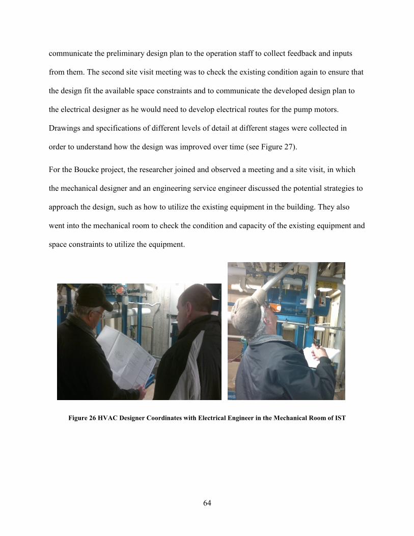
64
communicate the preliminary design plan to the operation staff to collect feedback and inputs
from them. The second site visit meeting was to check the existing condition again to ensure that
the design fit the available space constraints and to communicate the developed design plan to
the electrical designer as he would need to develop electrical routes for the pump motors.
Drawings and specifications of different levels of detail at different stages were collected in
order to understand how the design was improved over time (see Figure 27).
For the Boucke project, the researcher joined and observed a meeting and a site visit, in which
the mechanical designer and an engineering service engineer discussed the potential strategies to
approach the design, such as how to utilize the existing equipment in the building. They also
went into the mechanical room to check the condition and capacity of the existing equipment and
space constraints to utilize the equipment.
Figure 26 HVAC Designer Coordinates with Electrical Engineer in the Mechanical Room of IST

65
Figure 27 Design Drawings Collected from the Case Study Project
Based on the data collected from the case studies, two process maps were developed using
BPMN, each defining the captured design process of each project (see Appendix C). Note that
the projects selected for the case studies are different than the advanced retrofit projects studied
by this process modeling research in that the case study projects were small HVAC systems
retrofit projects in which major information needed for the major design decisions was
unambiguously defined and the designers needed to work under fixed constraints. For example,
for the IST pump replacement and reallocation project, the layout of the mechanical room and
other equipment that was not in the scope of the project would not change, which means all the
information needed for mechanical design was relatively fixed. This greatly simplified the early
stage of the concept and alterative exploration, and eliminated the guess work and the evolution
of design accuracy across phases. However, stripped of uncertainties and flexibilities, the process
maps developed from case studies reveal the core process components of HVAC design that
even the very small and simple HVAC design process should have. This means that the
components in the case study project process maps should be in the initial integrated HVAC
design process model too. Hence the process maps developed through case studies were cross

66
compared with the initial integrated HVAC design process model to check the validity and
supplement the initial HVAC design model.
5.3. Design Process Expert Workshop Discussions
5.3.1. Workshop Overview
A series of six expert workshops were the primary process map validation and improvement
method. The goal of the workshops was to develop a detailed HVAC design process map for a
typical retrofit project, so that the initial design process model could be cross compared and
validated. The method used to implement the workshops was to define a typical and
representative retrofit project, and then map the HVAC design process of that project during the
series of discussions. The workshops were conducted over a six week timeframe, with one
meeting per week. The number of the workshop participants varied. Two to three experienced
mechanical designers from the OPP Design Services Department and a workshop facilitator
experienced with interview and focus group techniques and familiar with OPP’s design practice
organized the workshop discussion. There were mainly two themes of workshop topics. One
focused on mapping the HVAC process for a certain phase. The workshop theme for the
following week was then targeted on a focus group discussion for the process maps developed in
the previous workshop. The two themes were discussed biweekly. Table 6 shows the themes of
each process workshop.

67
Table 6 Overview of Workshop Discussions
5.3.2. Workshop Design and Setup
The workshop activities took place at a conference room in the Physical Plant office, which is
the head quarter of OPP. A long 1-feet-wide sheet of white paper was posted on the wall, which
was used as a media for process mapping. Sharpies and sticky notes were used by workshop
participants to take notes and write down key activities. Figure 28 shows the setup of the
conference room.
Figure 28 Setup of the Workshop Discussion
No. Date Main Themes
1 Feb 1, 2012 Introduction to the thesis research and defining a
typical retrofit project
2 Feb 10, 2012 Mapping process to the end of SD phase
3 Feb 17, 2012 SD phase process review and discussion
4 Feb 24, 2012 Mapping the DD,SD phase design process
5 Mar 9, 2012 Continue mapping DD, CD phase process &
process review and discussion
6 Mar 23, 2012 Validation of the collected data & tailoring process
for OPP

68
Before every workshop, the researcher carefully designed a workshop plan including the
discussion themes, procedures, and key question lists. Those workshop plans were
communicated to a discussion facilitator whose responsibility was to keep the discussion running
by probing questions based on the discussion progress. During the process mapping discussions,
the researcher mainly acted as a documenter who took notes and a supporter who made sure the
workshop plan were well implemented by asking the areas that needed further discussion. For
the process mapping workshop, the typical discussion process was that the researcher first asked
designers to define the deliverables at the end of the phase, and then define the initial status of
design at the beginning of the phase. With the starting point and end point in mind, the
participants mapped the process of a phase. Every workshop was voice recorded. After every
workshop, the researcher transcribed the recording and analyzed the transcript. This transcript
analysis process helped the researcher to identify areas that needed further discussion so that he
was able to adjust the strategy and focus, and be more targeted during the following workshop.
The following provide a brief description of the process and deliverables in each workshop.
Workshop 1: A research introduction was provided and a discussion of the typical retrofit
project as a reference for the workshop discussion was conducted. In this workshop, the
overall research and process mapping goals were introduced. With the understanding to the
end goal, the designers and researchers discussed and defined a brief program for the typical
project that will be used as the base of discussion in the following workshop discussion.
Workshop 2: mapping the HVAC process from project start to the end of schematic design
phase. Based on the typical project defined in the previous week, the participants discussed
the design phasing and mapped out the design process of the schematic design phase.

69
Figure 29 shows the process maps developed during the workshop discussion.
Figure 29 Map Developed for Schematic Design Phase
Workshop 3: Through analyzing the transcript of last workshop, the researcher found that
the sequential relationships among the activities need clarification. In this workshop, each
participant was given a small process map with sticky note activities arranged randomly,
they were then asked to rearrange the activities into the correct order (Figure 30). The
processes created by different people were compared and the reasons for any difference were
discussed. Through the discussion, participants reached consensus on the sequence of the
major schematic design activities.

70
Figure 30 Map from SD phase Process Rearranging Activity
Workshop 4: Following the typical discussion process, which included going through the
process with the starting point and end point status of the phase definition, the design
development and construction document phase activities were mapped.
Workshop 5: Based on the overall process defined in the previous workshop, the participants
developed the process in further detail and identified deliverables and information exchanges
along the process (see Figure 31).
Figure 31 Sticky Note Process Map of DD and CD phase

71
Workshop 6: The entire design process was defined by the end of the fifth workshop. A
complete process map was developed using BPMN. In this workshop, the participants went
through and reviewed the entire process map with two goals. The first goal was to check if
the map accurately reflected the previous discussions. The second goal was to discuss how
OPP at Penn State design differently than the typical design process. As a conclusion of the
workshop, the participant confirmed the accuracy of the process map. No single activity was
changed in the process of tailoring the typical process map to suit the practice of OPP. The
only minor improvement was adding some information exchanges that are unique to OPP.
The OPP designer commented that although OPP has its own practice, the design in OPP
still needs to go through all the activities in the process map, the only difference is that some
steps at OPP are condensed, or sometimes certain information is already known so designers
can skip the activity that generates the information, in which situation, it is not that the step
is not needed, but that the work has been done before during a previous project that the
designers already have the experience and answer so that they do not need to do that
investigation again.
Through the six workshops, the researcher developed a detailed and accurate process map
that contains the core steps in designing HVAC systems. Figure 32 is a snapshot of the entire
process map (a detailed version is included in Appendix C). The result of the sixth workshop
shows that this process map is quite representative and at a general level of detail that it
covers the essential functions needed to deliver a HVAC system design. Along with the
process map, the researcher also compiled a transcript of the workshops that include over
twelve thousands words of process discussion. The process map, along with the transcript,
were then used to cross compare with the initial integrated HVAC design process model

72
developed in the first research stage to validate the process model and supplement the
process model description.
Preliminary Size and Locate Major Equipment Based on Zones
Estimate Block Heating & Cooling Load
Room by Room Volume/Load Calculation
Define Distribution Systems
Define Owner’s Criteria & Preference
Investigate Field Condition
Define Owner’s Criteria &
Preference
Investigate Existing Field
Condition
EstimateSquare Foot
Load
Preliminarily Define System
Types
Define initial Scope of Design
Estimate Cost
Establish Energy & Performance
Goals
Present Design Plan to Owner
Rough Space Needed
Coordinate With Other Disciplines
Preliminarily Selecting
Equipment Types
Program Adjustment & Assessment
Owner’s Feedback
Major Adjustment?
No
Yes
Updated Schematic Architectural Plans
Estimate Block Heating &
Cooling Load
Preliminarily Size and Locate
Major Equipment
Based on Zones
Define Major Distribution Space Need
Space Allocation for Distribution
Routes(Plenum, Riser Shaft)
Rough Space Requirement Info to Architects
(Ceiling Heights, Riser Shaft)
Equipment WeightTo Structural
Major Electrical Loads Estimate (Chiller/Cooling Tower/Heat Pump)
Scope Narratives
Updated Budget
Spec Sections Drawings
Coordination with Electr.
Struct. Arhit.
Review and Feedbacks
Cost Estimate
Existing Mechanical Space
Preliminary Select & Size
Major Equipment
Coordinate Space Need
with Architects
Locate Major Equipment
Define Block Zoning Based on Occupancy
Estimate Block Heating &
Cooling Load
Program Requirement
Program Requirement
Owner’s Project Requirements
Architectural Plan Updates
Basis of Design
Room by Room Volume/Load
Calc(Group into
zones)
Confirm and Adjust Major
Equipment Size
Create Drawing Details
Define/ Develop Specs & Control
SchemesDesign Review
Final Room Layout
Structure IssuesArchitectural Sections
Sequence of Operation& Schematic Control
Diagram
Full Spec/drawings
Budget/Construction Schedule
Occupancy Info
Room by Room Load Calc
Room Level Detailed Zoning
Define Distribution
Systems
Size Local Distribution
System
Layout Local Distribution
System
Check Space Conflicts
Update Drawings & Equipment Schedule
Size & Layout Major
Distribution System
Cost & Schedule Estimate
Investigate Existing Space
LayoutCollect Existing
Drawings &Documents Investigate
Existing Equipment Condition
Check Existing Utilities
Investigate Existing Space
Occupancy
Coordinate with Other
Disciplines
44 Activities.21 Info Objects
Define Owner’s Goal of the
Project
Define Owner’s Energy
Requirements
Understand Owner’s Budget
Limits
Understand the Owner’s Schedule
Constraints
Understand the Owner’s Quality & Performance
Criteria
Understand Owner’s
Preference to Systems and
Manufacturers
Owner’s Previous Project Preference
Maintenance Team Input
Owner Approval?
Yes
Load Calculation for Detailed Zones
Impact of Aesthetics
Available Utilities
Previous Project Experience
System Selection Manual
Penn State Design & Construction Standard -Division 23
Penn State Design & Construction Standard -Division 23
Penn State Design & Construction Standard -Division 23
Update Drawings &
Specs
Obtain Authority Approval
Individual activities
Collaborative activities
Locate Equip & Distr
Diffusers, Heating Cooling Coils, VAV Boxes, Room
Duct/Pipes, Terminal fans
This process can be done automatically in load calculation process(Such as H.A.P. carrier)
Mechanical Shaft, etc.
Match: IBPM: D.51 Develop Post Design
DwgMatch:D.52:
Develop Post-design Spec
Match:D.53 Perform
Design Review
This shows phase D.5 in IBPM matches CD phase in traditional phasing(reflect in
phasing table)
Match: D.54: acquire
approval
Pumps, boilers,
chillers, AHUs
Figure 32 The Process Map Developed from Workshops with OPP
5.4. Data analysis and Process Map Cross Comparison
Extensive data has been collected through the case studies and workshop activities, including
three different process maps, and over thirteen-thousand words of process documentation. With
those data, process validation and improvement started, which consisted of two parts. The first
part focused on analyzing the documenting data to extract useful information that either matches
the initial integrated HVAC design process model or is valuable to be added into the process
model. The second part focused on developing the process maps cross comparison, which
analyzes the activity sequence across four maps and identifies the parts of process that matche
each other or disagree with each other. The following introduces how data analysis and process
map cross comparison was performed.

73
The process maps developed from the case studies and workshop discussions only address the
key steps and information collected in the data acquisition process. More detailed and illustrative
data were embedded in the discussions and interviews. The documentation analysis process
focused on extracting information from transcripts and documentations developed in this
research stage. The researcher reviewed the transcripts and documentations several times and
highlighted important information. The information that contributed to the process map
validation and improvement were identified, noting how that piece of information was used by
the process model. Some comments show that the documentation contains information that
directly matches the initial integrated HVAC design process model, which validates the model.
For example, in the first image of Figure 33, what the workshop participant said matches an
information object of the model, so it was marked out and the information object was validated.
There are also other examples that the information in the documentation matches an activity in
the model or the sequential relationship in the process model. Some comments show that the
documentation contains information that supplements the definition of an existing component in
the process model or contributes new components to the process model. For example, the second
image in Figure 33 shows two information objects were added to the map; the third image in Figure
33 shows that the documentation helps the development of the process explanation. Some
comments show that the documentation contains information that helps locate activities or define
the sequential relationship. The fourth image in Figure 33 is an example. There are also comments
that summarize, paraphrase and explain the documentation.

74
Figure 33 Documentation of Workshop Activities
The second step was to compare the process map developed from workshop discussions and case
studies with the initial integrated HVAC design process model. Figure 34 and Figure 35 illustrate
this map cross comparison process by providing an example of map comparison of the Discovery
Phase. In Figure 34, the map on the top is the schematic phase process developed from workshop
discussion, the bottom map is the initial integrated HVAC design process model that has been
checked and revised through the documentation analysis process. Some activities are common
across the two maps. No action was taken to those activities. Some important activities in the
upper process map that did not have corresponding activities in the bottom process map were
added into the bottom map. For example, “Define Owner’s Preference and Criteria” was
identified as important since it determines the overarching goals and objectives of the project and
affects many later design decisions. This activity was, however, missing in the bottom map, so it
was added at the very beginning of the process. “Investigating Existing Field Condition” is also
an important activity for retrofit projects, which is also missing in the bottom map, so it was
Image 4
Image 1
Image 2
Image 3

75
added to the corresponding location in the map. In addition, some activities were refined so that
they are more specific and clear. For instance, the “Collect Design Planning Info” was replaced
by “Collect Existing Drawings and Documents”. In addition, as the phasing division of the upper
map is different than the bottom one, some activities (noted on the map) are used to compare
with the process of another phase of the initial integrated HVAC design process model. All the
changes made during the map cross comparison were documented in a change log spreadsheet.
Figure 35 shows a part of the change log (see Appendix F for full change log), which keeps track
of the types of the object (activity or information object), the type of change
(add/delete/relocate/refine), and the basis or source of the changes. The map at the bottom of
Figure 35 shows the discovery phase process after the process map cross comparison. In the entire
process map cross comparison process, around a hundred changes were made to the initial
integrated HVAC design process model. After going through the two-step process map
validation and refinement process, the intermediate integrated HVAC design process model was
developed.

76
Wo
rksh
op
Pro
cess
– S
chem
atic
Des
ign
Define Owner’s
Criteria & Preference
Investigate Existing Field
Condition
EstimateSquare Foot
Load
Preliminarily Define
System Types
Define initial Scope of Design
Estimate Cost
Establish Energy &
Performance Goals
Present Design Plan to Owner
Rough Space Needed
Coordinate With Other Disciplines
Preliminarily Selecting
Equipment Types
Program Adjustment
& Assessment
Owner’s Feedback
Major Adjustment?
No
Yes
Previous Project Experience
System Selection Manual
Init
ial I
nte
grat
ed H
VA
C D
esig
n P
roce
ss M
od
el –
Dis
cove
ry P
has
e REF
EREN
CE
INFO
.H
VA
C D
ESIG
N P
RO
CES
SIN
FO
EXC
HA
NG
E
Define Design Criteria & ParametersEstablish
Project Goals & Objectives
Define Spatial Requirements
Performance Criteria
Assimilate and Analyze Information
Establish Design
Parameters
Collect Design Planning Info
Establish Scope of the HVAC Design
Establish Energy Goals & Objectives
Design Planning Info
Estimate Preliminary
Load
Define Preliminary
HVAC Spatial Requirements
Define HVAC Performance
Criteria
Establish HVAC Budget Constraints
Establish Quality Control
Guideline
Establish HVAC
Schedule Requirements
Basis of Design
Previous Project Experience
Owner’s HVAC requirements
Building Shape& Type
Discovery Phase
Need info from architects
Figure 34 Process Maps Used for Cross Comparison
Added
here
Collect
Existing
Drawings,
Documents
Added
here
Moved to Level
2 of Defining
Owner’s Criteria
Match
Match
Match
Belongs to another Phase according to
Integrated Phasing
Definition
Match
Match
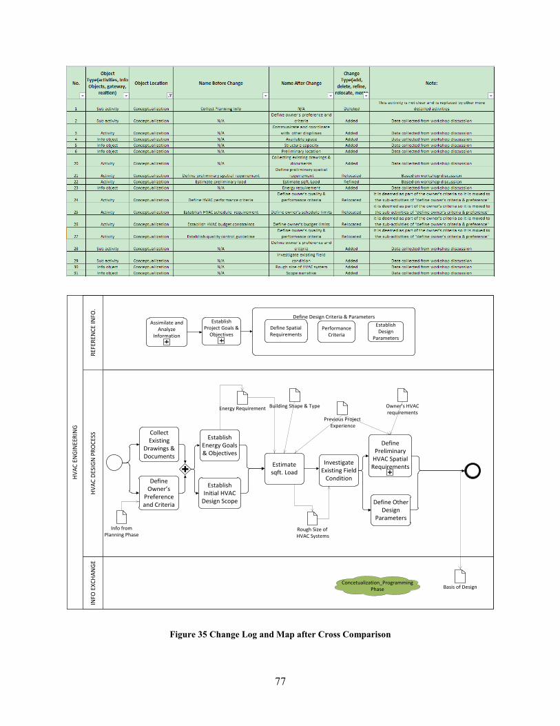
77
HV
AC
EN
GIN
EER
ING
REF
EREN
CE
INFO
.H
VA
C D
ESIG
N P
RO
CES
SIN
FO E
XC
HA
NG
E
Define Design Criteria & ParametersEstablish
Project Goals & Objectives
Define Spatial Requirements
Performance Criteria
Assimilate and Analyze
Information
Establish Design
Parameters
Define Owner’s
Preference and Criteria
Establish Initial HVAC
Design Scope
Establish Energy Goals & Objectives
Estimate sqft. Load
Define Preliminary
HVAC Spatial Requirements
Basis of Design
Previous Project Experience
Owner’s HVAC requirements
Building Shape & Type
Investigate Existing Field
Condition
Info from Planning Phase
Collect Existing
Drawings & Documents
Define Other Design
Parameters
Rough Size of HVAC Systems
Energy Requirement
Concetualization_Programming Phase
Figure 35 Change Log and Map after Cross Comparison

78
5.5. Integrated Feature Enhancement
At this point of the research, the integrated HVAC design process model contained the essential
activities needed in the HVAC design process and organized those activities into an integrated
design framework. A review of the process showed that the process model lacked strong
integrated design attributes except for a number of collaborative design activities. To enhance the
integrated HVAC design process model with more integrated attributes, a new round of literature
content analysis was conducted to identify more attributes for integrated design.
The integrated design attributes is defined here as those features or characteristics of design that
can exist in both integrated and traditional design, but the adoption and implementation of those
attributes in the design process will facilitate the collaboration of different design participants
and support their integrated design behaviors thus improving the integration level of a design
process.
The researcher further analyzed the Integrative Design Guide (7group and Reed 2009), AIA IPD
Guide (American Institute of Architects 2007), the ASHRAE Advanced Energy Design Guide
for small to medium office buildings and K-12 school buildings (ASHRAE 2008, ASHRAE
2011), and the IBPM (Sanvido et al. 1990). Several integrated design attributes were identified
including:
Life-cycle costs bundling analysis;
Collaborative key decision making throughout the process;
Integration of expertise from downstream participants, such as fabrication expertise, and
operation and maintenance expertise;
Early collaborative goals and performance metrics definition; and
Heavy BIM implementation along the process to inform design decisions.

79
Besides identifying the integrated design attributes, portions of the process maps with those
attributes were also identified from previously reviewed literature. The process maps were
further compared with the integrated HVAC design process model and a series of activities that
carry the integrated design attributes were added into the process model. The activities that carry
the integrated design attributes were color coded with red in the process model.
Another benefit of adding those activities carrying the integrated design attributes is that many of
those activities are not HVAC system specific. They are performed collaboratively by multiple
parties and are even led primarily by the architect(s) and the owner. During the development of
this integrated HVAC system design process model, several process models for other disciplines,
such as structure, architectural, and lighting system, were being developed through a
complementary activity. Therefore these activities could serve as a unified integration gateway
across different process models of other disciplines, connecting the independent process models.
5.6. Further Validation through Interviews and Process Comparison
The previous validation of the HVAC process model was completed with HVAC designers in
OPP. In order to eliminate the OPP-specific process data, the researcher performed further
validation through interviewing senior HVAC designers in an AE firm, and compared the
integrated HVAC design process model against another independently developed HVAC design
process model.
5.6.1. Process Validation through Interviews
Two one-hour interviews were conducted with two senior HVAC designers in a large, integrated
AE firm whose major projects are retrofit projects. The goal of the interviews was to check if the
content of the integrated HVAC design process model was accurately reflective of integrated

80
practice. The interviewees were not shown any of the developed process maps and asked to
answer questions designed by the researcher. The question list was designed based on the latest
process maps. Questions were asked to check if the activity sequence matches their practice and
verify if they perform the activities shown on the process maps. The interview transcripts were
analyzed using the same content analysis method in the previous validation process.
5.6.2. Process Map Comparison
US Army Corps Engineers (USACE) developed and released HVAC design process maps for
facilities (Hitchcock et al. n.d.). The process maps were release during the validation phase of
this research activity so they were not originally available to use as a source for model
development. Therefore, they were used in the validation process to compare two independent
activities focused on making the process. The USACE maps contain 41 activities and 60
information objects, each with a paragraph description. The researcher compared the two sets of
independently developed maps as a further validation. The comparison results show that all key
content in the USACE process maps is addressed in the integrated HVAC design process model
and most activities sequential relationships in USACE maps match the ones in the integrated
HVAC design process model. This further indicates the model is consistent with other literature
and process maps.

81
6. The Integrated HVAC Design Process Model
This chapter shows parts of the integrated HVAC design process model as an example to
illustrate how the process maps are structured and what are the components on each process map.
Readers can find the full version of the process model and process descriptions in Appendix A
and Appendix B.
Figure 36 is the discovery phase process map of the integrated HVAC Design Process Model.
The upper swim lane, called “REFERENCE INFO.” contains information that needs to be
referenced by the activities. For example, the activity “Define Owner’s Preference and
Requirements on HVAC Systems” needs to reference the Owner’s Project Requirements (OPRs)
as an input for performing the activity. The middle swim lane, called “HVAC DESIGN
PROCESS”, contains the activities of the HVAC design process. The bottom swim lane contains
the information that is exchanged within the process or the information output from the HVAC
system to other disciplines. The tittle box is at the very bottom, which shows the name and level
of map, and the number of activities and information objects in the process map. This process
model has three levels of detail. The highest level, Level 0, shows the different phases of the
design process. The middle level, Level 1, shows the high level activities in each primary design
phase. The bottom level, Level 2, shows the more detailed process that is the expansion of the
activities in Level 1. Color coding is used for all Level 1 activities. The blue activities are regular
activities that can be performed by the HVAC design team, while the red activities are to be
performed in an integrated manner by the integrated design team. Some activities have a plus
sign at the bottom of the activity box, which means they can be further expanded into a more

82
detailed Level 2 process map, the map numbers of which are shown in the small yellow boxes
attached to the bottom of those activities.
HV
AC
EN
GIN
EER
ING
REF
EREN
CE
INFO
.H
VA
C D
ESIG
N P
RO
CES
SIN
FO E
XC
HA
NG
E
Preliminarily Estimate
Building Load
Define Preliminary
HVAC Spatial Requirements
Initial Basis of Design
Previous Project Experience
Owner’s HVAC requirements
Building Info: Shape, Orientation, Type, etc.
Owner’s Project Requirements
(OPRs)
Collect Existing
Drawings & Documents
Establish System
Performance Parameters
Rough Size of HVAC Systems
Energy Goals and Performance Targets
Define Owner’s Preference and
Requirements on HVAC Systems
1.1.1
Existing ConditionsAnd Resources
Load Estimate Guide
Investigate and Survey
Existing Building
1.1.2
Establish Energy Goals &
Performance Targets
1.1.3
Map Name 1.1_Discovery Phase
Map Level Level 1 Activities Info Objects7 9Integrated HVAC Design Process Model
Figure 36 Discovery Phase of the Integrated HVAC Process Model
Each Level 1 activity has a paragraph description, which can be found in Appendix B. The
process model description is organized by phase and by the sequence of activities in each process
map. For example, the activity “Preliminarily Estimate Building Load” is the third activity in the
Discovery phase, so its description can be found in the corresponding location in the Appendix B.

83
Figure 37 Activity Description

84
7. Conclusion
In chapter summarizes the process model development research. Contributions of this research
are listed and elaborated. The limitation of this research is also discussed, and the corresponding
potential future research to provide solutions is discussed.
7.1. Research Summary
This research is part of the enterprise architecture research initiative, supported by the Energy
Efficient Building (EEB) Hub funded by the US Department of Energy. The goal of this
enterprise architecture research project is to support the energy efficient building design by
developing an integrated building life-cycle process model at the building system level, and
targeting energy retrofit project.
The goal of this research was to develop a process model describing the HVAC system design
process for the advanced energy retrofit projects for implementation in an integrated design and
delivery approach. A four-step methodology was used to achieve this goal. The research started
with an extensive literature review and content analysis of previous process models and design
guides. Together with the information collected from several interviews with experienced
designers, a preliminary HVAC process model was developed through a comparison of the
various process data. Through the content analysis process, the Integrated Building Process
Model (IBPM) was identified as a framework for process model development. The preliminary
process model was then integrated into the Integrated Building Process Model (IBPM)
framework, which generated the initial HVAC design process model. The researcher then
validated the initial process model through a series of process mapping workshop, focus group

85
discussions and two case studies. Significant process data were collected during the process
model validation process, which helps with both the validation and further development of the
initial process model. After the initial process model being validated, the researcher did another
round of literature review and analysis to incorporate more integrated design attributes into the
integrated HVAC design process model in order to improve the integration level of the process
model. At the conclusion of this research, a process model was developed which contains 16
sub-process maps, 110 activities and 51 information inputs, outputs, and exchanges among the
design activities. A process model explanation was also developed, which introduces the
definition and work scope of each HVAC design phase, and the definition of all Level 2 design
activities. Table 7 shows the statistics of the process model.
Table 7 Process Model Statistics
ITEM COUNT
Maps 15
All Activities 103
Collaborative Activities 12
Independent Activities 91
Information Objects 60
7.2. Contributions
Three major contributions of this research are described in this section.
7.2.1. Contribution to Process Modeling
Many researchers have developed a variety of process models for different phases of a project
and for various purposes. This thesis performed an in-depth literature review of various design

86
process models, which is valuable for future research. In addition, this research developed a
process model that describes the HVAC system design process in a level of detail that exceeds
the previous process literature. The process model developed in this research also addresses the
specific need of energy retrofit projects and an integrated design approach. In addition to
documenting and describing the process, the integrated HVAC process model also identifies key
information inputs, outputs, and exchanges among the design activities. This process model is
developed to a level of detail that can be used as a reference for design planning and execution.
The design team members can use this process model as a basis for communication and
coordination. They can use this process model as a template and tailor this process model to
develop their project specific design planning map.
7.2.2. Contribution to Integrated Design
Through reviewing literature on integrated design, the researcher developed an integrated design
phasing method for energy retrofit projects using a new set of terms adopted from AIA
Integrated Project Delivery Guide. This new phasing method was based on the integrated design
principles such as pushing the design effort upstream, and increasing the iteration and
exploration of the design alternatives at the early design phases. The research also identified
several integrated design attributes that, if adopted in design process, can improve the design
performance and facilitate the collaboration among the design participants, thus improving the
integration level of the design.
7.2.3. Contribution to the National Building Information Model Standard (NBIMS) Effort
The first step of the approach proposed by the NBIMS is to get groups of experts to develop the
Information Delivery Manuals (IDMs), which specifies the business processes and the

87
information exchange requirements (Building Smart Alliance 2010). However, currently the
development of IDMs is typically not performed to the level of breadth of the proposed HVAC
process map. The process model developed in this research can serve as a foundation to open
discussions to systematically identify key information exchanges throughout the process, from
which people can easily identify the needs for IDMs. The developed IDMs can also be tied to the
process model to show the location and context of the process model, which helps people to
better understand the IDMs.
7.3. Limitations and Future Research
One limitation of this research is that the integrated process model was developed without
intensively considering and referencing the process of other disciplines, which makes this
process a one sided “integrated process”. Future research should examine this process from the
perspective of the constraints and inputs from other disciplines, so that the HVAC discipline
process can better integrate with other discipline processes and more smoothly connect with the
integrated building lifecycle building process model.
Another limitation is that although this HVAC process model has been validated through various
methods and with people from different organizations. This process model has not been validated
on an integrated design project. Future research should compare this process model with the
process documents from integrated design projects.
Due to the time limitations, the researcher did not identify the appropriate categories of Building
Information Modeling (BIM) tools that support the activities in the process model. The value of
this research is that through identifying the categories of BIM tools that supports different
activities in the process model, we can further identify the information exchange requirements

88
between different categories of BIM tools. Knowing how information is exchanged within the
process and what categories of BIM tools are used for the two activities that exchange
information, we can easily understand the number of required information exchange
requirements that are needed to successfully execute the process and develop a clear definition of
each. This would be valuable for future IDM and Model View Definition (MVD) development.

89
References
7group, and Reed, B. (2009). The Integrative Design Guide to Green Building: Redefining the
Practice of Sustainability. Wiley, New York, NY.
American Institute of Architects. (2007). “Integrated Project Delivery: A Guide, Contract
Documents.” <http://www.aia.org/contractdocs/AIAS077630> (Nov. 23, 2011).
Anjard, R. (1998). “Process mapping: a valuable tool for construction management and other
professionals.” Facilities, 16(3/4), 79–81.
ASHARE. (2011). Advanced energy design guide for small to medium office buildings :
achieving 50% energy savings toward a net zero energy building. American Society of
Heating, Refrigerating and Air-Conditioning Engineers, Atlanta, GA.
ASHRAE. (2008). Advanced energy design guide for K-12 school buildings : achieving 30%
energy savings toward a net zero energy building. ASHRAE, Atlanta, Ga.
Austin, S., Baldwin, A., Li, B., and Waskett, P. (1999). “Analytical design planning technique: a
model of the detailed building design process.” Design studies, 20(3), 279–296.
Austin, S., Baldwin, A., and Newton, A. (1994). “Manipulating the flow of design information to
improve the programming of building design.” Construction management and economics,
12(5), 445–455.
Austin, S., Baldwin, A., and Newton, A. (1996). “A data flow model to plan and manage the
building design process.” Journal of Engineering Design, 7(1), 3–25.
Baldwin, A., Austin, S., Thorpe, A., and Hassan, T. (1995). “Simulating quality within the
design process.” Computing in Civil Engineering (1995), 1475–1482.

90
Baldwin, A. N., Austin, S. A., Hassan, T. M., and Thorpe, A. (1999). “Modelling information
flow during the conceptual and schematic stages of building design.” Construction
Management and Economics, 17, 155–167.
Browning, T. R. (2002). “Process integration using the design structure matrix.” Systems
Engineering, 5(3), 180–193.
Building Smart Alliance. (2010). “National BIM Standard | Whole Building Design Guide.”
<http://www.wbdg.org/bim/nbims.php> (Mar. 27, 2011).
CBECS. (2008). Electricity Consumtion (Btu) by End Use for All Buildings.
Charette, R. P., Marshall, H. E., Standards, N. I. of, and (US), T. (1999). UNIFORMAT II
elemental classification for building specifications, cost estimating, and cost analysis. US
Dept. of Commerce, Technology Administration, National Institute of Standards and
Technology.
Chung, E. K. (1989). A Survey of Process Modeling Tools. Technical Report, Penn State
University CIC research group.
Computer Integrated Construction Research Program. (2010). BIM Project Execution Planning
Guide - Version 2.0. The Pennsylvania State University, University Park, PA, USA.
DiCicco-Bloom, B., and Crabtree, B. F. (2006). “The qualitative research interview.” Medical
Education, 40(4), 314–321.
Dufresne, T., and Martin, J. (2003). “Process modeling for e-business.” În: Information Systems
Department, George Mason University, L. Kerschberg (ed).
Hancock, B. (1998). An introduction to qualitative research. Trent focus group.
Hensen, J. L. M., and Lamberts, R. (Eds.). (2011). Building Performance Simulation for Design
and Operation. Routledge.

91
Hitchcock, R., Wilkins, C., and Tanis, M. (n.d.). “Ontology for Life-Cycle Modeling of Heating,
Ventilating, and Air Conditioning (HVAC) Systems: Model View Definition.”
IDM technical Team. (2007). “Quick Guide: Business Process Modelling Notation (BPMN).”
Kagioglou, M., Cooper, R., Aouad, G., and Protocol, P. (1998). A generic guide to the design
and construction process protocol. Process Protocol.
Kagioglou, M., Cooper, R., Aouad, G., and Sexton, M. (2000). “Rethinking construction: the
generic design and construction process protocol.” Engineering construction and
architectural management, 7(2), 141–153.
Kaneta, T., Furusaka, S., Nagaoka, H., Kimoto, K., and Okamoto, H. (1999). “Process Model of
Design and Construction Activities of a Building.” Computer‐Aided Civil and
Infrastructure Engineering, 14(1), 45–54.
Karlshøj, J. (2011). “Information Delivery Manuals: Process Mapping.”
<http://iug.buildingsmart.com/idms/training-
material/IDM_ProcessMapping_20110703.pptx/view> (Oct. 26, 2011).
Krippendorff, K. (2004). Content analysis: an introduction to its methodology. Sage, Thousand
Oaks, California.
Lapinski, A. (2005). Delivering Sustainability: Mapping Toyota Motor Sales Corporate Facility
Delivery Process. The Pennsylvania State University, 102.
Lapinski, A., Horman, M., and Riley, D. (2005). “Delivering Sustainability: Lean Principles for
Green Projects.” ASCE Conference Proceedings, 183(40754), 6.
Marshall, C., and Rossman, G. (1999). Designing qualitative research. Sage Publications, Inc.,
Newbury Park , CA.

92
Material Laboratory. (1981). “Integrated Computer Aided Manufacturing Function modeling
manual.”
McDowall, R. (2006). Fundamentals of HVAC Systems (IP): IP Edition Hardbound Book.
Elsevier Science.
McQuiston, F. C., Parker, J. D., and Spitler, J. D. (2004). Heating, Ventilating and Air
Conditioning Analysis and Design. Wiley.
Mulhall, A. (2003). “In the field: notes on observation in qualitative research.” Journal of
Advanced Nursing, 41(3), 306–313.
Myers, M. D., and Newman, M. (2007). “The qualitative interview in IS research: Examining the
craft.” Information and Organization, 17(1), 2–26.
National Action Plan for Energy Efficiency. (2008). Sector Collaborative on Energy Efficiency
Accomplishments and Next Steps.
Norton, K. (1989). An Integrated Facility Design Process Model. Technical Report No. 4, Penn
State University CIC research group.
Pahl, G. (2007). Engineering design: a systematic approach. Springer Verlag, London.
Pektas, S. T., and Pultar, M. (2006). “Modelling detailed information flows in building design
with the parameter-based design structure matrix.” Design Studies, 27(1), 99–122.
Petersdorff, C., Boermans, T., and Harnisch, J. (2006). “Mitigation of CO2 Emissions from the
EU-15 Building Stock. Beyond the EU Directive on the Energy Performance of
Buildings (9 pp).” Environmental Science and Pollution Research, 13(5), 350–358.
Polit, D. F., and Hungler, B. P. (1998). Nursing Research: Principles and Methods. Lippincott
Williams & Wilkins, Philadelphia.
Pretzlik, U. (1994). “Observational methods and strategies.” Nurse Researcher, 2(2), 13–21.

93
Pugh, S. (1990). Total design: integrated methods for successful product engineering. Addison-
Wesley Wokingham,, UK.
Pugh, Stuart. (1986). “Design activity models: worldwide emergence and convergence.” Design
Studies, 7(3), 167–173.
RIBA. (1973). “RIBA Plan of Work For Design Team Operation.” RIBA Publications.
Rodgers, D. (2009). “About the Office of EERE: Testimony of David Rodgers.”
<http://www1.eere.energy.gov/office_eere/rodgers_testimony_032609.html> (Nov. 28,
2011).
Rounce, G. (1998). “Quality, waste and cost considerations in architectural building design
management.” International Journal of Project Management, 16(2), 123–127.
Sanvido, V. E., Khayyal, S. A., Moris, G., and Michael, H. (1990). An integrated building
process model. Computer Integrated Construction Research Program, Department of
Architectural Engineering, the Pennsylvania State University.
Sanvido, V. E., and Norton, K. J. (1994). “Integrated Design-Process Model.” Journal of
Management in Engineering, 10, 55–62.
Stein, B., and Reynolds, J. S. (1999). Mechanical and Electrical Equipment for Buildings, 9th
Edition. Wiley.
White, S. A. (2004). “Introduction to BPMN.” IBM Corporation, 31.
Wix, J. (2007). Information Delivery Manual: Guide to Components and Development Methods.
The Norwegian buildingSMART Project. http://idm. buildingsmart.
no/confluence/download/attachments/446/IDM2_Methodology. pdf, accessed.

94
Wix, Jeffrey. (2006). “HVAC Engineering- Process Maps (PM).”
<http://idm.buildingsmart.no/confluence/display/IDM/HVAC+Engineering+%28PM%29>
(Jan. 8, 2012).
Womack, J. (2003). Lean thinking : banish waste and create wealth in your corporation. Free
Press, New York.
Wu, S., Fleming, A., Aouad, G., and Cooper, R. (2001). “The Development of the Process
Protocol Mapping Methodology and Tool.” Conference on International Postgraduate
Research in the built and human environment.

95
Appendix A: Integrated HVAC System Design Process Model
(Starting from Next Page)
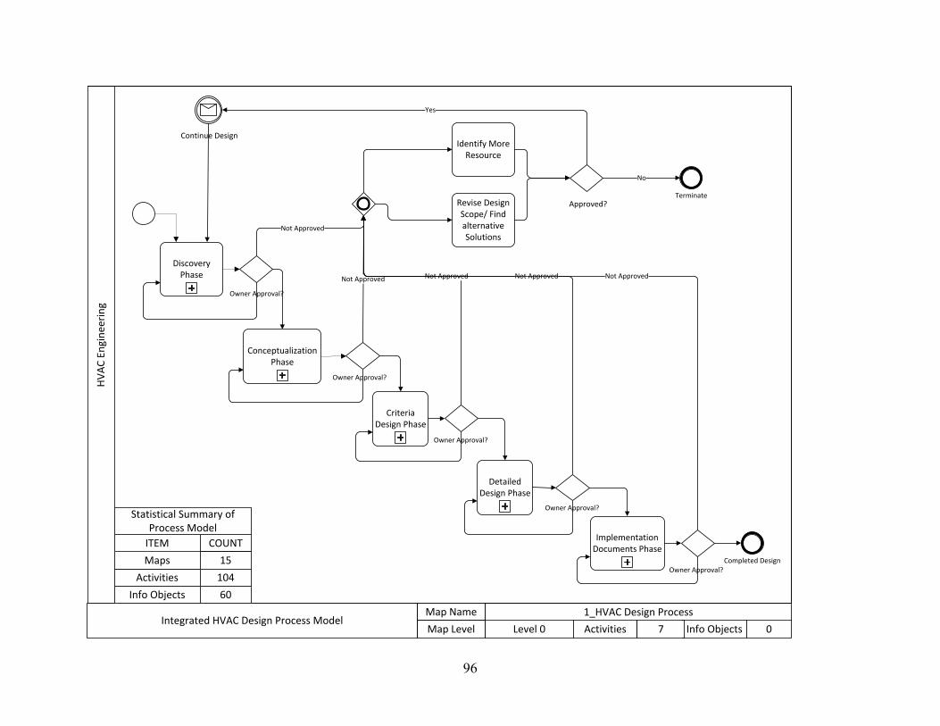
96
HV
AC
En
gin
eeri
ng
Conceptualization Phase
Criteria Design Phase
Detailed Design Phase
Implementation Documents Phase
Not Approved Not Approved Not Approved Not Approved
Owner Approval?
Owner Approval?
Owner Approval?
Owner Approval?
Discovery Phase
Owner Approval?
Not Approved
Identify More Resource
Revise Design Scope/ Find alternative Solutions
Approved?
No
Yes
Continue Design
Map Name 1_HVAC Design Process
Map Level Level 0 Activities Info Objects7 0Integrated HVAC Design Process Model
Info Objects
Activities
Maps
ITEM COUNT
15
104
60
Statistical Summary of Process Model
Terminate
Completed Design

97
HV
AC
EN
GIN
EER
ING
REF
EREN
CE
INFO
.H
VA
C D
ESIG
N P
RO
CES
SIN
FO E
XC
HA
NG
E
Preliminarily Estimate
Building Load
Define Preliminary HVAC
Spatial Requirements
Initial Basis of Design
Previous Project Experience Owner’s HVAC
requirements
Building Info: Shape, Orientation, Type, etc.
Owner’s Project Requirements
(OPRs)
Collect Existing Drawings & Documents
Establish System
Performance Parameters
Rough Size of HVAC Systems
Energy Goals and Performance Targets
Define Owner’s Preference and
Requirements on HVAC Systems
1.1.1
Existing ConditionsAnd Resources
Load Estimate Guide
Investigate and Survey Existing
Building
1.1.2
Establish Energy Goals &
Performance Targets
1.1.3
Map Name 1.1_Discovery Phase
Map Level Level 1 Activities Info Objects7 9Integrated HVAC Design Process Model

98
HV
AC
EN
GIN
EER
ING
REF
EREN
CE
INFO
.H
VA
C D
ESIG
N P
RO
CES
SIN
FO E
XC
HA
NG
E
Define Owner’s HVAC Related Project Goals
Understand Owner’s
Preference to Systems and
Manufacturers
Owner’s Previous Project Preference
Maintenance Team Input
HVAC SystemsBudget Limits
HVAC SystemsSchedule Constraints
HVAC Energy Requirements
HVAC SystemsQuality &
Performance Criteria
Owner’s Project Requirements
(OPRs)
Define Owner’s Functional
Requirements for Space
Establish Initial HVAC Design
Scope
Map Name 1.1.1_ Define Owner’s Preference & Requirements on HVAC Systems
Map Level Level 2 Activities Info Objects4 7Integrated HVAC Design Process Model

99
HV
AC
EN
GIN
EER
ING
REF
EREN
CE
INFO
.H
VA
C D
ESIG
N P
RO
CES
SIN
FO
EXC
HA
NG
E
Investigate Existing Space
Layout
Investigate the Condition and
Location of Existing
Equipment
Investigate Available Utilities
Investigate Existing Space
Occupancy
Evaluate Building
Envelope and Openings
Map Name 1.1.2_Investigate and Survey Existing Building
Map Level Level 2 Activities Info Objects4 0Integrated HVAC Design Process Model
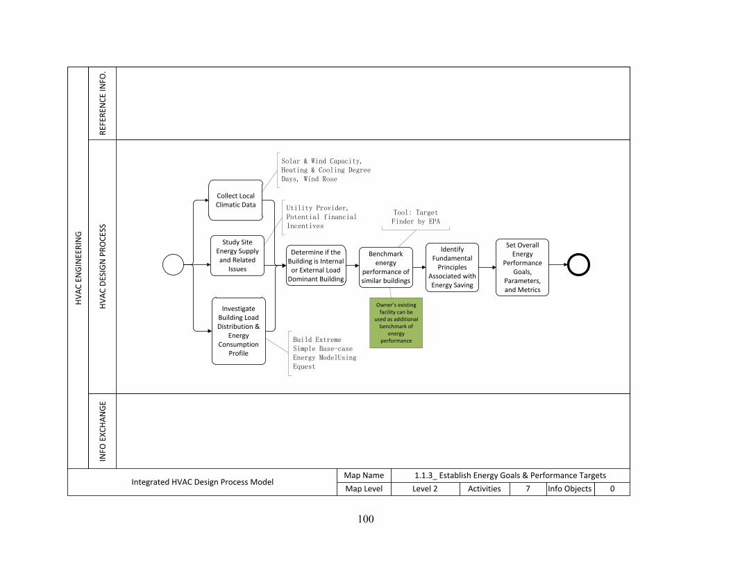
100
HV
AC
EN
GIN
EER
ING
REF
EREN
CE
INFO
.H
VA
C D
ESIG
N P
RO
CES
SIN
FO E
XC
HA
NG
E
Collect Local Climatic Data
Study Site Energy Supply and Related
Issues
Determine if the Building is Internal
or External Load Dominant Building
Benchmark energy
performance of similar buildings
Identify Fundamental
Principles Associated with Energy Saving
Set Overall Energy
Performance Goals,
Parameters, and Metrics
Investigate Building Load Distribution &
Energy Consumption
Profile
Map Name 1.1.3_ Establish Energy Goals & Performance Targets
Map Level Level 2 Activities Info Objects7 0Integrated HVAC Design Process Model
Owner’s existing facility can be
used as additional benchmark of
energy performance
Utility Provider, Potential financial Incentives
Solar & Wind Capacity, Heating & Cooling Degree Days, Wind Rose
Build Extreme Simple Base-case Energy ModelUsing Equest
Tool: Target Finder by EPA

101
HV
AC
EN
GIN
EER
ING
REF
EREN
CE
INFO
.H
VA
C D
ESIG
N P
RO
CES
SIN
FO E
XC
HA
NG
E
Run Energy Models to Help Evaluate And Select Load Reduction Strategies
DesignScope Narrative
Identify Potential Load
Reduction Strategies
Identify Feasible Major System
Types
Reduced Load
Perform Preliminary
HVAC System Study
1.2.1
Map Name 1.2_Conceptualization
Map Level Level 1 Activities Info Objects4 2Integrated HVAC Design Process Model

102
HV
AC
EN
GIN
EER
ING
REF
EREN
CE
INFO
.H
VA
C D
ESIG
N P
RO
CES
SIN
FO
EXC
HA
NG
E
Collect Related Information
Study Activity Comfort Needs
Study Activity Schedule
Study Climate Design
Strategies
Code Conformance
Study
Spatial Relationship
Study
Map Name 1.2.1_Perform Preliminary HVAC System Study
Map Level Level 2 Activities Info Objects5 0Integrated HVAC Design Process Model
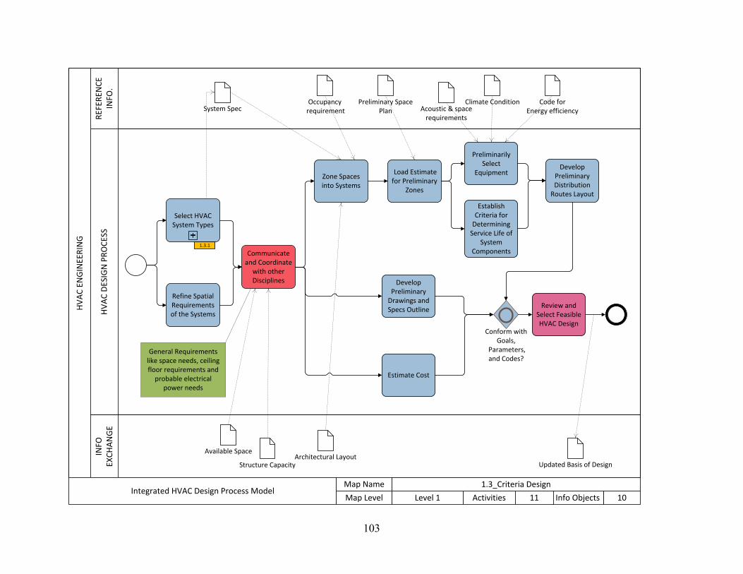
103
HV
AC
EN
GIN
EER
ING
REF
EREN
CE
INFO
.H
VA
C D
ESIG
N P
RO
CES
SIN
FO
EXC
HA
NG
E
Refine Spatial Requirements of the Systems
Develop Preliminary Distribution
Routes Layout
Develop Preliminary
Drawings and Specs Outline
Estimate Cost
Conform with Goals,
Parameters, and Codes?
Review and Select Feasible HVAC Design
Zone Spaces into Systems
Load Estimate for Preliminary
Zones
Architectural Layout
System Spec
Preliminarily Select
Equipment
Establish Criteria for
Determining Service Life of
System Components
Occupancy requirement
Communicate and Coordinate
with other Disciplines
Structure Capacity
Available Space
Climate Condition Code for Energy efficiency
Select HVAC System Types
1.3.1
Updated Basis of Design
Preliminary SpacePlan Acoustic & space
requirements
Map Name 1.3_Criteria Design
Map Level Level 1 Activities Info Objects11 10Integrated HVAC Design Process Model
General Requirements like space needs, ceiling floor requirements and
probable electrical power needs

104
HV
AC
EN
GIN
EER
ING
REF
EREN
CE
INFO
.H
VA
C D
ESIG
N P
RO
CES
SIN
FO
EXC
HA
NG
E
Evaluate SystemsDecide on
Comfort Ranges and Adaptive
Thermal Comfort
Parameters Evaluate the Skill Level of the
Maintenance and Operation
Staff
Decide the Complexity of
the HVAC Systems
Identify Occupancy Schedule
Perform Additional
Modeling Runs to Inform the Lifecycle Cost
Analyses
Estimate System Lifecycle
Cost
Evaluate Space Needs
System Energy Consumption
System LifecycleMaintenance
Requirements
Initial System Cost
Select System Based on the
Analysis
Map Name 1.3.1_Select HVAC System Types
Map Level Level 2 Activities Info Objects8 3Integrated HVAC Design Process Model

105
HV
AC
EN
GIN
EER
ING
REF
EREN
CE
INFO
.H
VA
C D
ESIG
N P
RO
CES
SIN
FO E
XC
HA
NG
E
Estimate Major
Distribution Space Need
Create Ducts/Pipes Schematics
Rough Space Requirement Info to Architects
(Ceiling Heights, Riser Shaft)
Equipment WeightTo Structural
Major Electrical Loads Estimate
(Chiller/Cooling Tower/Heat Pump)
Scope Narratives
Coordinate with Electr.
Struct. Arhit.
Existing Mechanical Space
Owner’s Project Requirements
Architectural Plan Updates
Basis of Design
Impact of Aesthetics
Program Requirement
Updated Schematic Architectural Plans
Equipment Location
Confirm and Adjust Major Equipment
Size
Create Drawing Details
Define/ Develop Specs & Control
Schemes
Final FloorPlan
Sequence of Operation& Schematic Control
Diagram
Full Spec/drawings
Occupancy Info
Update Drawings & Specs
Yes
Detailed Zone Loads
Review Drawings & Specs
Perform Energy
Simulation
Update Cost
Estimate
Owner Approval?
Estimate Block Zone Heating &
Cooling Load
1.4.1
Select and Locate Major
Equipment Based on
Block Zones
1.4.2
Group Individual Space into
Zones & Load Calc
1.4.3
Map Name 1.4_Detailed Design
Map Level Level 1 Activities Info Objects14 17Integrated HVAC Design Process Model
Define Distribution
Systems
1.4.4
Pumps, boilers,
chillers, AHUs

106
HV
AC
DES
IGN
PR
OC
ESS
Define Block Zoning Based on Occupancy
Estimate Block Heating &
Cooling Load
Program Requirement
HV
AC
DES
IGN
PR
OC
ESS
Select & Size Major
Equipment
Locate Major Equipment
Coordinate Space Need
with Architects
Map Name 1.4.1_Estimate Block Zone Heating & Cooling Load
Map Level Level 2 Activities Info Objects2 1Integrated HVAC Design Process Model
Map Name 1.4.2_Select and Locate Major Equipment Based on Block Zones
Map Level Level 2 Activities Info Objects3 0Integrated HVAC Design Process Model

107
HV
AC
EN
GIN
EER
ING
REF
EREN
CE
INFO
.H
VA
C D
ESIG
N P
RO
CES
SIN
FO E
XC
HA
NG
E
Use Load Calculation Software to Define Load for Detailed Zones
Develop Detailed Zones at Room Level by Grouping Rooms
with Similar Load Profile into a Zone
Calculate Load for Detailed
Zones
Detailed Zone Loads
Floor Plan Occupancy Cost Constraints
Map Name 1.4.3_Group Individual Space into Zones & Load Calculation
Map Level Level 2 Activities Info Objects2 4Integrated HVAC Design Process Model

108
HV
AC
EN
GIN
EER
ING
REF
EREN
CE
INFO
.H
VA
C D
ESIG
N P
RO
CES
SIN
FO E
XC
HA
NG
E
Size & Layout Local
Distribution Equipment &
Terminal Units
Coordinate with Architects & Lighting and
Electrical Desginers
Detailed Zone Loads
Estimate Loads at Key Points
Sum up Branch Loads back to
Major Distribution
System
Estimate Diversity Factor
Regulate Distribution
Systems
Distribution System Space Needs
Space Characteristics
Size & Layout the Main
Distribution Routes
Branch Load
Create Air Flow Diagrams
Map Name 1.4.4_Define Distribution Systems
Map Level Level 2 Activities Info Objects8 4Integrated HVAC Design Process Model
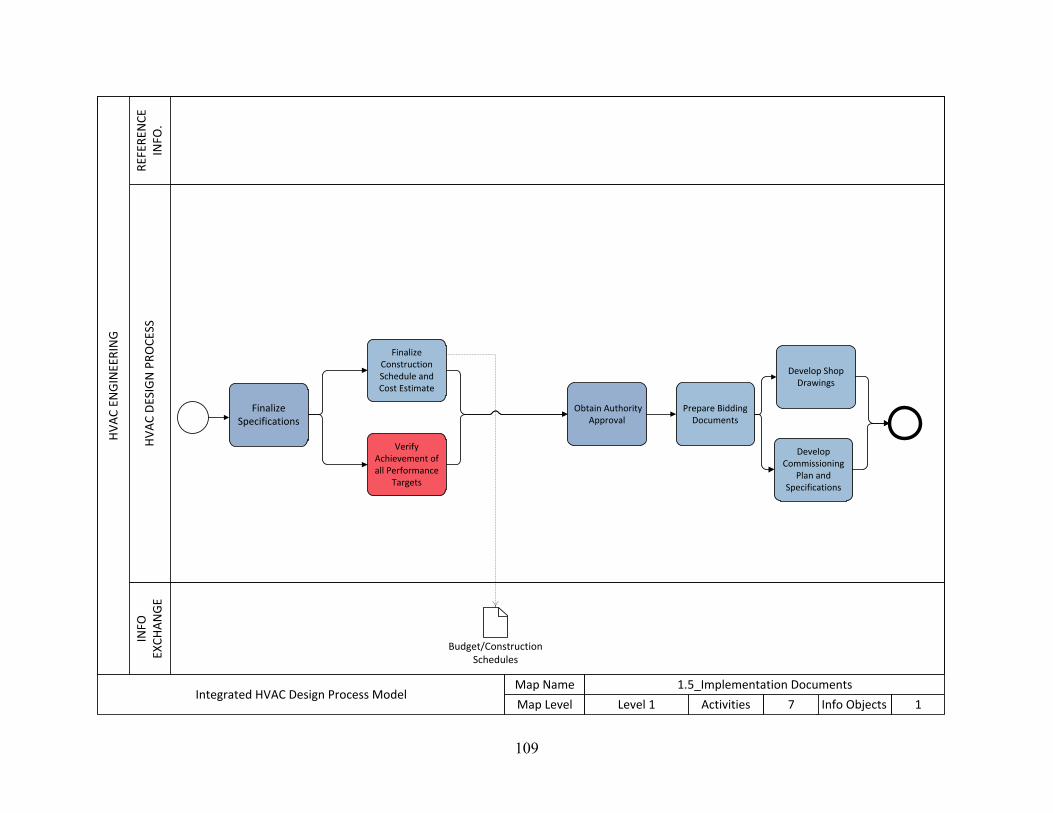
109
HV
AC
EN
GIN
EER
ING
REF
EREN
CE
INFO
.H
VA
C D
ESIG
N P
RO
CES
SIN
FO
EXC
HA
NG
E
Finalize Construction Schedule and Cost Estimate
Develop Shop Drawings
Prepare Bidding Documents
Verify Achievement of all Performance
Targets
Obtain Authority Approval
Finalize Specifications
Develop Commissioning
Plan and Specifications
Budget/Construction Schedules
Map Name 1.5_Implementation Documents
Map Level Level 1 Activities Info Objects7 1Integrated HVAC Design Process Model

110
HV
AC
EN
GIN
EER
ING
REF
EREN
CE
INFO
.H
VA
C D
ESIG
N P
RO
CES
SIN
FO
EXC
HA
NG
E
Prepare Input for the Load Program
Calculate Internal Load
Load Calculation Models(Carrier Hap, Trane Trace, DOEII)
Calculate External Load
Calculate Ventilation Load
Sum Load
Load Information
Define the Goal of Load Estimate
Select Load Estimate Program
Do area Takeoff
Define Area Uses & Occupancy
Define the Goal of Load Estimate
Climate Data
Map Name Load Estimate Process
Map Level Level 2 Activities Info Objects10 2Integrated HVAC Design Process Model
NOTE: This process applies to all the Load Estimate Activities in this process model, though in different stages of the design the level of detail of the load estimate is different
Computer Aided Process
Breakdown Process
111
Appendix B: Process Model Description
DISCOVERY PHASE
The discovery phase is similar to the traditional predesign and programming phase. Two major
goals are pursued in this phase. First, the project inputs and project context information are
collected, compiled and organized. Thorough field investigation should be performed to
understand the facility and identify field and project specific energy saving opportunities. Second,
the owner’s needs and requirements are studied and defined, the Owner’s Project Requirements
(OPR) is reviewed by the design team through a series of collaborative design meetings to
establish HVAC related project performance targets and design parameters, and identify site
specific opportunities and risks. The constraints and the boundary of the project are also studied.
The boundary can be physical, such as the size and type of the area and the space program. It can
be technical, such as the outlet number and type and the material type. It can also be financial,
such as investment budget or Life Cycle Cost.
Define Owner’s Preference and Requirements on HVAC Systems
This activity is important as it determines the overarching goal of the project related to HVAC
systems. Many later design decisions will be referencing the result of this activity. The design
strategy would be very different if the owner wants to have a LEED platinum building and use it
as their headquarter, versus the owner is a developer and wants to sell the building as soon as
possible. This activity should be done early in the process so that the designers can proceed with
right direction and strategies. The owner’s project requirement(OPR) is an important input and
reference to this activity. In this activity, the owner’s goal will be defined, and then the owner’s
overall energy, schedule, budget, and quality goals will be defined. The HVAC design scope of

112
work will need to be discussed and negotiated with the owner. Attention should be paid on
owner’s functional space requirements in OPR. Besides, the owner’s preference of HVAC
systems and manufacturers will be documented through research on owner’s other facilities and
talks with owner’s maintenance personnel. (See Lvl 3 process map for expanded process)
Collect Existing Drawings & Documents
At the beginning of the design, in order to obtain a good understanding to the existing facility,
the designers need to collect as-built drawings and other records documenting changes of the
building during its life-cycle.
Preliminarily Estimate Building Load
Based on the records and drawings collected, make a preliminary estimate of the building HVAC
load so that the mechanical engineers have a sense of feasible types of system and know the
rough space needed for the systems and equipment. Knowing this rough space requirement and
the potential size of the system helps the designers perform a more targeted site survey and
investigation. First round of energy modeling can be implemented to help with the preliminary
load estimate.
Information for estimating loads at the discovery stage will typically be derived from previous,
similar projects or from collected 'rules of thumb' (which are effectively aggregated data from
multiple previous, similar projects). Such calculations will make broad assumptions about
contributions to load resulting from lighting or other energy sources rather than using
information contributed to the building model from other roles.

113
Investigate and Survey Existing Building
Investigate and survey existing building is the activity that the designers visit the existing
building to verify the existing drawings and documents and obtain additional information of the
facility that is not on the drawings. This is an important data collection activity that supplement
the previous “collect the existing drawings and documents” activity, the information collected
from which usually are not complete and clear or contain information that is out of date. In the
investigation and survey, designers walk through the building and site to assess the condition of
the existing building systems and available resources. Key things that need attention are: the
layout of the building, the type and occupancy of the existing space, type, condition and location
of existing equipment on service, constraints of existing structure, building envelope and
openings and the available utilities, like gas, chilled water etc. Initial assessment will be made on
the existing HVAC equipment to see what part of the existing equipment is serviceable and can
be salvaged and used.
Establish Energy Goals and Objectives
Establishing the owner’s/the project’s energy goals and objectives can be achieved through the
following steps.
• Study Site Energy Supply and Related Issues
Investigate the energy sources, microclimates, utility providers, potential financial incentives,
and other additional issues that may impact the site energy supply
• Investigate Building Load Distribution & Energy Consumption Profile
Previously an initial energy model has been developed to help with the load estimate.
Referencing the additional information collected from field survey and investigation, run a

114
refined simple energy model to inform the designers about the distribution of loads by energy
consumption end use. Create an energy-load-distribution chart from the results of the model.
• Determine if the Building is Internal or External Load Dominant Building
Based on the previous analysis, determine if the building is dominated by internal load or
external load. This will impact the design strategies. For example, for external load dominant
building, the performance of the building envelope has a greater impact on the building energy
performance. Usually, external load dominant building are small commercial or residential
buildings, large commercial buildings tend to be internal load dominant (7group and Reed 2009).
• Benchmark energy performance of similar buildings
The goal of using energy modeling during design is to not to give design team absolute
prediction, but enable them to make relative comparisons. The designers should benchmark an
appropriate energy consumption based on the owner’s previous record and similar projects.
The Target Finder Tool created by the U.S. EPA can be used for researching the typical energy
performance for buildings of similar building type and location. The owner’s existing facilities
could be used for setting benchmarks and energy performance targets(7group and Reed 2009).
• Translate Fundamental Principles of Energy Saving to Performance Targets
The fundamental principles of energy saving are “Creating less demand via use of insulation,
demand patterns, reduced loads, etc.”; “Use available site energies, such as solar, wind, earth
coupling, and diurnal cycles.”; “Increase efficiency of equipment, appliances, diversity factors,
etc.”(7group and Reed 2009) The translated performance targets, take the first principle as an

115
example, can be the R value of the wall should be no less than certain amount, the load should be
reduced by certain percentage, etc.
• Set Overall Energy Performance Goals, Parameters, and Metrics
Overall energy performance expectations for the project are discussed. Based on the overall
energy performance targets and expectation, the performance parameters and metrics are
addressed (IDP,p.132)
Define Preliminary HVAC Spatial Requirements
Based on the preliminary load estimate, information collected from the field investigation,
previous project experience and industry guidance, make a preliminary estimate of the space
required for major technical spaces to serve the HVAC systems on a project. Major technical
spaces are spaces that have a substantial impact on building consideration in terms of their
structural implication (special floors etc.). Other (minor) technical spaces will be determined at
the conceptualization stage. Estimate of the space requirement may include height requirement
(e.g. need for 5m height for the type of equipment being considered). Example: A major
technical space could be for a chiller or cooling tower plant space or mechanical room. The
space requirement can be determined on a factor based method that takes into account total space
area and space function.
Establish System Performance Parameters
Based on the energy performance goals and targets defined in the previous step, performance
parameters related to HVAC system sizing, thermal comfort, and so on are proposed and
established. These specific parameters will be used to guide the initial design effort. (IDP)

116
CONCEPTUALIZATION PHASE
The conceptualization phase is similar to the traditional conceptual design phases. This phase is a
collaborative process of proposing, evaluating, comparing various strategies against the OPR and
ranking the various strategies. First important research needed to be done in this stage is the load
reduction strategies. Energy models are analyzed to help select the most appropriate strategies.
At the end of this phase, the design is still very vague with broad concepts. The project team
should reach a consensus on major design parameters, building parameters and the major design
strategies for meeting the OPR. Their coordinated concepts should be presented to the owner for
approval. The owner’s comments will be reflected in the later phases.
Perform Preliminary HVAC System Study
Collect information that is necessary but not delivered from upstream steps. Perform studies on
codes and regulations, climate design strategies, activity schedule and so on.
Benchmark Energy Performance of Similar Buildings
The goal of using energy modeling during design is to not to give design team absolute
prediction, but enable them to make relative comparisons. The designers should benchmark an
appropriate energy consumption based on the owner’s previous record and similar projects. A
tool that can be used to determine if the energy modeling result is within reasonable scope is the
Environmental Protection Agency’s Target Finder.
Discuss Potential Load Reduction Strategies
At this point of design, the energy modeling should focus on load-reduction strategies before
analyzing HVAC system options.

117
Run Energy Models to Help Evaluate and Select Load Reduction Strategies
In this step, the load reduction strategies proposed and discussed in previous step is evaluated
according to each strategy’s potential for downsizing the HVAC systems. The reduced load will
be used as a basis for evaluating HVAC systems, and the design should continue assuming this
reduced load.
Identify Feasible Major System Types
Based on the reduced load and other information about the building, designers perform a first
round feasibility review of system types and narrow down the feasible system types.
CRITERIA DESIGN
The criteria design phase is the process of refining and expanding the feasible concepts selected
in the previous phase. At this stage, the most appropriate HVAC system types, like VAV, DOAS,
and chilled Beam etc., and their configurations are explored based on the load reduction
strategies defined in the previous phase. Strategies and resources needed by the design team are
identified. All the relevant principles and solutions are analyzed and coordinated with other
disciplines. A final system schematic defining the logic of the HVAC system is selected for
detailed design.
Select HVAC Systems Types
At this point of the project, the design team should be able to select a certain type of HVAC
systems from the several systems alternatives being evaluated in the conceptualization phase.
The system configuration will be defined. Traditionally, HVAC systems types are divided by the
media used to transfer heat, such as all air, air-water, all water, and direct refrigerant systems.

118
Some other system types mentioned by ASHARE (50% energy guide) include Ground Source
Heat-Pump System, Dedicated Outdoor Air System, Fan-Coil System, and VAV Air-Handling
System.
Refine Spatial Requirements of the systems
Based on the analysis and selection of the HVAC system types, the HVAC designers update and
propose the system spatial requirements based on the more detailed information and the industry
space types library.
Communicate and Coordinate with Other Disciplines
Coordination and communication with other disciplines happen along with selecting systems.
The space need and the location of the HVAC systems need to coordinate with the architects.
The aesthetic aspect, such as if something is going to be left outside or hidden, needs to be
confirmed with architects too. The location and weight of systems need to coordinate with
structural engineers if the system may be big and heavy. Electrical engineers need to know where
power is needed and roughly how much power is needed, therefore the capacity and location of
the systems should be communicate with electrical engineers. Compatibilities checks with other
systems, quality reviews, and code conformance checks are also performed.
Zone Spaces into Systems
Group spaces into big zones based on the system selected. The space grouped together should be
conditioned by the same particular system.
Load Estimate for Preliminary Zones
Refine the preliminary load and estimate loads for the big zones defined for each system.

119
Preliminarily Select Equipment
For each HVAC system, select one or more feasible sets of HVAC equipment. It is good to have
a general idea of the rough equipment location, size, number, and weight so that other disciplines
can provide feedback to the equipment selection. The equipment selection at this point of time
should serve the purpose of supporting the evaluation of the equipment options. Once the most
feasible equipment options are decided, the equipment selection will go further in detailed design
phase.
Establish Criteria for Determining Service Life of System Components
To perform an accurate lifecycle cost analysis for the system components, it is important to know
the equipment life and maintenance cost. In this step, the HVAC designers need to reach consent
of how they are going to assess the service life of the system components. A resource that the
design team can reference is the “Equipment life and maintenance cost survey” written by MT
Akalin in 1978.
Develop Preliminary Drawings and Specification Outline
Develop preliminary drawings and spec section outlines to document the design progress of this
phase. Examples of the things that may be included are: floor plans showing zoning, single line
duct run, and equipment schedules that shows the general size and performance of the equipment.
Develop Preliminary Distribution Routes Layout
Develop a very preliminary sketch for the major distribution routes if the available information
allows.

120
Review and Select HVAC Design
The design team along with the owner review, evaluate, judge, and select the best design
alternatives based upon criteria such as cost data, project requirements, energy efficiency and
design parameters. The best design and its energy model are passed along for further
development.
DETAILED DESIGN
The detailed design phase is a process of taking the qualitative design decisions in criteria phase,
performing quantitative analysis of the alternatives, and adding detailed system pieces. At the
end of this phase, all the system components are fully and unambiguously defined, coordinated
and validated. Simulations of the systems and overall design are also conducted at the end to
review the design. Development of preliminary specifications, drawings, and schedules begins in
this phase.
Estimate Block Zone Heating & Cooling Load
This activity contains two steps. First is to further divide the broad zones for different systems
into more detailed block zones based on the programming and occupancy requirements and the
owner’s need. For example, the owner may want certain area of the building to be conditioned 24
hours a day or during the vacations when other equipment is shut down. In that case, an
independent zone needs to be identified for that space. After the zoning is further defined for the
specific need of space, the load of each block zone is then calculated to support subsequent
HVAC related decision making.

121
Select and Locate Major Equipment Based on Block Zones
Based on the need of different zones and the space constraints, the designers select and size
major equipment, and then under the coordination with the architects, structural and electrical
engineers, locate major equipment, which includes Air Handling Units (AHU), Chillers, Boilers,
Pumps, etc.
Estimate Major Distribution Space Need
Estimate the space need for the major distribution systems based on the loads for each part of the
building. For example, the space need of platinum and mechanical rooms.
Create Ducts/Pipes Schematics
Starting from the location of the major equipment, sketch out single line distribution routes for
ducts and pipes. Based on the constraints of space and other equipment, the sketches need to be
adjusted to find a most efficient route.
Coordinate with Electrical Engineers, Structure Engineers, and Architects
The HVAC design is coordinated with the design of electrical engineers, structure engineers, and
architects to make sure that the HVAC design won’t conflict with the need of other building
systems. The HVAC designers need to inform the equipment location and their aesthetics impact
on the building to the architects. The equipment location and weight of the equipment needs to
be coordinated with structure engineers. The location and electrical load of the equipment needs
to be communicated and coordinated with the electrical engineers.
Group Individual Space into Zones & Load Calculation
This step can be done in load calculation programs. First calculate the load of each space, and
then group rooms with similar load profile into detailed zones and perform load calculation for

122
the detailed zones. The information that needs to be referenced by the HVAC designers during
this process is the space occupancy and the budget limit, which will determine how many
detailed zones there need to be. The budget limit needs to be considered because more zones are
usually more costly.
Define Distribution Systems
This is a sub-process. This sub-process encompasses the layout and sizing of all the distribution
systems, both local room level and major distribution systems.
Create Air Flow Diagrams
The HVAC designers establish what the air flow is for each space and the selected HVAC
systems.
Size & Layout Local Distribution Equipment & Terminal Units
Sizing and laying out the terminal units and the branch distribution equipment in each detailed
zone based on their load. The location distribution equipment includes diffusers, room duct/pipes,
and terminal fans. The terminal units are those local heat exchange units such as heating and
cooling coils, VAV boxes with reheat coil, etc. Besides the constraints from lighting and other
disciplines, the layout of the local equipment depends on the space characteristics, which are the
shape, volume and heat exchange boundaries of the space. For example, if the space is a square
room, a 500 CFM diffuser may serve the need, but if the space is a very narrow and long space,
we may need two 250 CFM diffusers instead.
Estimate Loads at Key Points
Estimate the load at the key points along the distribution routes.

123
Size & Layout the Main Distribution Routes
Size & layout the main distribution routes that connects the distribution branches with the major
equipment. This could be an iterative activity that may require some tweaking of routing layout
depending on the coordination needs with other disciplines.
Sum up Branch Loads back to Major Distribution System
Add the estimated loads progressively back to the estimated point at which the major distribution
equipment, e.g. pumps and fans, will be located. This will provide an estimated load which the
major distribution system and major equipment are required to meet.
Estimate Diversity Factor
Estimate a diversity factor for HVAC supply that considers the expected maximum simultaneous
load on the system given that not all HVAC distribution may be required at the same time.
Regulate Systems
Establish regulation settings to the distribution systems. For example, a balancing damper needs
to be set to 20% closed to achieve the required air flow through a branch duct.
Coordinate with Architects & Lighting and Electrical Designers
Coordinate the location of the terminal units, pipes, and ducts to architects, lighting designers
and electrical designers.
Confirm and Adjust Major Equipment Size
Based on the total load summed up from the branches, calculate the maximum load on the major
equipment, which is the nominal or design requirements for the maximum thermal power
addition or extraction required to maintain specified conditions in all building thermal zone

124
spaces. Confirm and adjust the size and capacity of the major equipment to meet the updated
total load.
Perform Energy Simulation
Detailed whole-building energy simulations are performed on the design to determine if
optimization, corrections, and the like are necessary. If the HVAC design does not meet the
energy expectations or other requirements, the design will return to the beginning of this phase.
Create Drawing Details
Create equipment detail drawing sheets and other drawing details.
Update Drawings & Specifications
Update the progress to drawings and specifications.
Define/Develop Specs & Control Schemes
Specification is developed. Detailed sequence of operation and schematic control diagram
showing all the devices and sensors that are required to be accomplished in the sequence of
operation are developed. The control scheme will be delivered to a control contractor.
Review Drawings & Specs
Coordinate documents between various disciplines. Perform final reviews and checks.
Update Cost Estimate
Update the cost estimate to include the cost of the additional details developed in this phase.

125
IMPLEMENTATION DOCUMENTS
The implementation documents phase should be a process of documenting how the design will
be implemented based on the detailed design documentation. Contractors create shop drawings.
BIM models are finalized.
Finalize Specifications
Specifications at this point should be substantially complete. However, the integrated design
approach and the energy saving focus taken by the design team may lead to the adoption of new
technologies, products, construction techniques, and commissioned installation methods that may
require more explicit specification and explanation of how the expected results are to be
achieved. Therefore the design team should check if there are needs to clarify the performance
standards and criteria for providing and executing each product and system.
Finalize Construction Schedule and Cost Estimate
Perform detailed cost estimate and schedule estimate for the construction process.
Verify Achievement of all Performance Targets
Complete the documentation of all performance criteria related to design performance targets.
Check if anything is missing during the Detailed Design Stage. For LEED projects, the status of
pursuing the targeted credits should be finalized. Make sure the responsibilities of providing
required documentation for all design credits are clarified.
Obtain Authority Approval
Generate documents for permitting, financing, and regulatory purpose and send all the required
documents for review and approval by the owner, legal counsel, and governmental agencies.

126
Prepare Bidding Documents
Prepare bidding documents for parties outside the integrated process.
Develop Shop Drawings
Develop shop drawings or models that clearly represent the geometry of the elements to be
fabricated.
Develop Commissioning Plan and Specifications
The scope of the commissioning which describes the systems to be commissioned shall be posted
in the commissioning specifications. A list of equipment in those systems will be developed. The
goal is to create a tracking form in the commissioning plan. For every equipment listed in the
commissioning tracking form, a construction checklist containing the parameters of the
equipment will be created in the commissioning plan. A functional performance test tracking
form will also need to be developed to guide the functional performance tests of the
commissioned systems and equipment. The functional performance tests tracking form needs to
outline the methodology for gathering the related information from submittals and design
documents that will enable the commissioning authority to developing testing protocols and
parameters to verify that the intended sequences of operations are functional.

127
Appendix C: Case Study and Workshop Maps
Case study process model:

128
IST
Pu
mp
Rep
lace
men
t P
roje
ct H
VA
C D
esig
n P
roce
ss
Develop Design Plan &
Alternatives
Check Existing Conditions
Collect Info from Operation
Team
Building Condition Info
Select Design Plan
Define Available Space and
Other Constraints and Requirements
Locate the Equipment
Initial Drawings
Understand the Project Goals and Context
Select Equipment
Develop Specs
Detail Drawings with Notes
Coordinate with Electrical Engineer
Send Design for Internal Review by Engineering
Services
Check Code Compliance by
Authorities
Drawings
Specs
Project Goals &Requirements
IST building renovation project:
129
Background:
The IST building’s heating systems have partially failed due to the poor quality of the heating water. The air and dirt in the heating
water has caused clogging up some of the heating water pipes and pumps, cutting the heat off in certain areas of the IST building.
Hence the goals of the project are: to swap the failure equipment; to install filter equipment to clean the heating water; and to move the
equipment to a more serviceable area.
Project Schedule: the design started slightly before Feb 8th
. The drawing phase will last a month, following which would be a two
weeks’ design review by other disciplines. The revision will take 2 weeks. And then the drawings will be sent out for code review.
First Meeting: Feb 8th
, 2012.
Attendees: HVAC engineer; Several maintenance and operation people.
Meeting activities:
To solve the heating problem in IST, the mechanical engineer had an initial plan to move the heat water pump from the crowed area to
an open area to create more space for the equipment. He also prepared alternative plan for this problem. He went to talk to the
maintenance team aiming to get more ideas from the field people, clarify the things that he is not very clear, verify the feasibility of
his plan options, and propose the plan to the maintenance team and get some feedbacks from them.

130
First, the mechanical engineer talked to operation personnel to communicate his design plan to them and try to understand the existing
conditions. His plan is to install an air-dirt separator and relocate the pump.
The operation personnel provided him information and status of the equipment.
After the brief communication, they walked into the where the problem equipment locates, they checked the constraints of the space,
such as the piping around and on top of the area where they plan to install the new equipment.
Next, they walked close to the problem pump, and checked the piping connection of the pump, as well as other pipes around the
pumps. Then they discussed the potential pipe routes and layout.
In the end, the mechanical engineer decided a most feasible renovation plan and have all his questions answered.
The factors that impact the design option selection are: workability, which means the easiness for the operation personnel to work with;
the maintainability, which will impact the long term cost of the equipment and design .
Second Meeting Feb 17th
, 2012
This week the mechanical engineer has measured the mechanical room and determined the new location of the equipment and then
draws them out in the drawings. He measured the space in the mechanical room and the clearance of electrical devices and maintained
spaces. Based on his measurement, he decided where he would like to relocate the heat pump. Distribution routes have been decided,
131
he tried to use the routes of the existing pipes that is going to be demolished, as the hangers and pipe support can be reused. The
design is 90% finished if no further changes occur.
Third Meeting Feb 24th
, 2012
The mechanical engineer detailed the drawings. Added note to the drawings and created specs.
Fourth Meeting Feb 27th
, 2012
The mechanical engineer met with an electrical engineer in the mechanical room in IST. They first checked the switchboard, identified
the switches that control the pumps that are going to be replaced. They then went to the pumps that are to be moved and replaced and
checked the space where the pumps will be moved to. The mechanical engineer told the electrical engineer where he wants to locate
the equipment and where the motors are needed. They then discussed the potential routes of the conductor. The mechanical engineer
also checked his current drawing against the existing pipes to make sure that he drew the pipes right.
The electrical designer needs to know the location of the mechanical equipment like pumps and panels to decide where he needs to run
the wire. In this specific project, the HVAC designer doesn’t need information from the electrical designers.

132
Bou
cke
Ren
ovat
ion
Proj
ect
HV
AC
desi
gn p
proc
ess
Project Site Investigation
Check existing condition
Define Preliminary
Design Options
Yes
NoRevise Design
ScopeCustomer Approval
Feasible? budget, schedule, Technical
Continue with typical design
process
Find More Resource/ Funding
Check As-built Drawings
Communicate with
Engineering Service
Walk around exterior to locate mechanical shaft
Check the Condition, Type and Capacity of
Existing AHU, Fans, Pumps, and
Pipe
Estimate the Space Constraints
for Adding/Expanding Equipment
Preliminary Estimate Project Feasibility and
Challenges
Yes
No
Find Alternative Solutions
Develop Design Plan

133
Boucke retrofit project:
Background and scope: Boucke building is owned by multiple owners. The retrofit project is going to change some offices on the 3rd
floor to classrooms. Some walls will be tore down to merge two offices to a bigger classroom. The classrooms need conditioning.
The difficulty of this project is that the owner of the offices does not possess the entire floor. The mechanical room is in the other side
of the building. The space in between belongs to other organizations. So it is hard to draw the duct passing other space and condition
only the owner’s space.
Existing condition introduction:
There is a big AHU in the mechanical room. The AHU is designed to cover half of the floor, while the customer only owns less than
20% of the area.
The capacity of the AHU is around 12,000, but the load is probably less than 1,000.
The AHU is not hooked up with duck, pipe, and control. It would be a sizable amount of money to connect them.
The probable plan is to use the existing fan-coil unit, though the designer is reluctant to do so, as the fan-coil is almost at the end of
their live cycles. The scope of work would be to move the ductwork around and relocate the diffusers.

134
Project Schedule:
The project feasibility study and field investigation started on Feb 2nd
. The Design was expected to start on Feb 13th
and last 3 wks
until March 3rd
.
First Meeting: Feb 2nd
, 8:00 am
Participants: A mechanical engineer and an engineer from Engineering Service (work with the operation personnel, provide field
support to equipment problems, and perform design reviews)
Task performed:
1. Discussed facility existing condition.
a. Communicated the scope of work
b. Communicated the status of existing equipment: location, year, type, capacity
c. Discussed possibility of utilizing existing systems
2. Discussed the options for satisfying the retrofit goals
3. Discussed the next steps
Site visiting: Feb 2nd
, 8:30. A mechanical engineer and staff in Engineering Service
Goal: to verify the drawings, as typically the as-built drawings are different than the actual site condition.
1. Walked around the exterior to locate the mechanical shaft.
2. Checked the mechanical room within the building.
a. Checked the type and capacity of existing AHU, return air fan.

135
b. Estimated the space constraints for adding ductwork and systems. Constraint of structure: brace beam could be an
obstacle for ducts. Constraints of adjacent spaces: do they have enough space for more ducts? It determines the
potential distribution route.
3. Preliminarily estimated the cost and feasibility of the project. Check if the project would be within budget or not. If not, report
up to communicate with the owner.
Second Meeting: Feb 6th
The meeting was to determine the availability of funding to assist in additions required to the existing air handling unit for this project.
They found out that even the slim chance that assistance is available, it won’t be in time to help with the project since it requires
summer construction. The mechanical engineer is in the process of determining the minimum amount of work required to meet the
code, and then he will propose this to the customer as their scope of work. It is doubtful the customer has the funding to use the
existing AHU?
Feb 10th
The designer had a meeting last Friday and discussed the use of the big Air Handling Unit. The outside engineering firm was tasked
with providing a design proposal and construction estimates. To date, nothing has been decided. The project is on hold until a scope
is determined, and the designer is not sure when that decision will be made, as it involves the upper levels of OPP management.
Several weeks later, decision was made that fund was available to hire an outside engineering firm to retrofit the entire floor of the
Boucke building, rather than part of the floor that is owned by the owner who initiated this project.

136
Process Map Developed from Workshops with OPP
Preliminary Size and Locate Major Equipment Based on Zones
Estimate Block Heating & Cooling Load
Room by Room Volume/Load Calculation
Define Distribution Systems
Define Owner’s Criteria & Preference
Investigate Field Condition
Define Owner’s
Criteria & Preference
Investigate Existing Field
Condition
EstimateSquare Foot
Load
Preliminarily Define
System Types
Define initial Scope of Design
Estimate Cost
Establish Energy &
Performance Goals
Present Design Plan to Owner
Rough Space Needed
Coordinate With Other Disciplines
Preliminarily Selecting
Equipment Types
Program Adjustment
& Assessment
Owner’s Feedback
Major Adjustment?
No
Yes
Updated Schematic Architectural Plans
Estimate Block Heating
& Cooling Load
Preliminarily Size and
Locate Major Equipment Based on
Zones
Define Major Distribution Space Need
Space Allocation for Distribution
Routes(Plenum, Riser Shaft)
Rough Space Requirement Info to Architects
(Ceiling Heights, Riser Shaft)
Equipment WeightTo Structural
Major Electrical Loads Estimate (Chiller/Cooling Tower/Heat Pump)
Scope Narratives
Updated Budget
Spec Sections Drawings
Coordination with Electr.
Struct. Arhit.
Review and Feedbacks
Cost Estimate
Existing Mechanical Space
Preliminary Select & Size
Major Equipment
Coordinate Space Need
with Architects
Locate Major Equipment
Define Block Zoning Based
on Occupancy
Estimate Block Heating
& Cooling Load
Program Requirement
Program Requirement
Owner’s Project Requirements
Architectural Plan Updates
Basis of DesignRoom by
Room Volume/Load
Calc(Group into
zones)
Confirm and Adjust Major Equipment
Size
Create Drawing Details
Define/ Develop Specs & Control
Schemes
Design Review
Final Room Layout
Structure IssuesArchitectural Sections
Sequence of Operation& Schematic Control
Diagram
Full Spec/drawings
Budget/Construction Schedule
Occupancy Info
Room by Room Load
Calc
Room Level Detailed Zoning
Define Distribution
Systems
Size Local Distribution
System
Layout Local Distribution
System
Check Space Conflicts
Update Drawings & Equipment Schedule
Size & Layout Major
Distribution System
Cost & Schedule Estimate
Investigate Existing
Space LayoutCollect Existing
Drawings &Documents
Investigate Existing
Equipment Condition
Check Existing Utilities
Investigate Existing Space
Occupancy
Coordinate with Other Disciplines
44 Activities.21 Info Objects
Define Owner’s Goal of the Project
Define Owner’s Energy
Requirements
Understand Owner’s
Budget Limits
Understand the Owner’s
Schedule Constraints
Understand the Owner’s
Quality & Performance
Criteria
Understand Owner’s
Preference to Systems and Manufacture
rs
Owner’s Previous Project Preference
Maintenance Team Input
Owner Approval?
Yes
Load Calculation for Detailed
Zones
Impact of Aesthetics
Available Utilities
Previous Project Experience
System Selection Manual
Penn State Design & Construction Standard -Division 23
Penn State Design & Construction Standard -Division 23
Penn State Design & Construction Standard -Division 23
Update Drawings &
Specs
Obtain Authority ApprovalDevelop
Preliminary Specs,
Drawings & Schedules
Locate Equip &
Distr
Diffusers, Heating Cooling Coils, VAV Boxes, Room Duct/Pipes, Terminal fans
This process can be done automatically in load calculation process(Such as H.A.P. carrier)
Mechanical Shaft, etc.
Match: IBPM: D.51
Develop Post Design
Dwg
Match:D.52: Develop
Post-design Spec
Match:D.53 Perform Design Review
This shows phase D.5 in IBPM
matches CD phase in traditional
phasing(reflect in phasing table)
Match: D.54:
acquire approval
Pumps, boilers, chillers,
AHUs