Embed Size (px)
Citation preview
Overseas DepartmentIndustrial Electronic Products Sales Division
NIPPON AVIONICS CO., LTD.3-20-1 Nishi Shinbashi, Minato-ku, Tokyo, Japan
Zip code: 105-0003TEL: +81-3-5401-7386 FAX: +81-3-5401-7344
Customer Support Center, Industrial Electronic Products Division1-1 KOYATO 2-CHOME SAMUKAWA-MACHI
KOZA-GUN KANAGAWA, JAPANZip code: 253-0103
Tel: +81-467-73-4426E-mail: [email protected]
URL: http://www.avio.co.jp
To customers : Enter the name and date of the store where you purchased thisproduct. This information will be useful when you ask your dealer forrepair.
• Date of Purchase (year, month, day)
• Store of Purchase
Telephone Number : ( )
AV
IO In
telligen
t Pro
jector iP
-750E
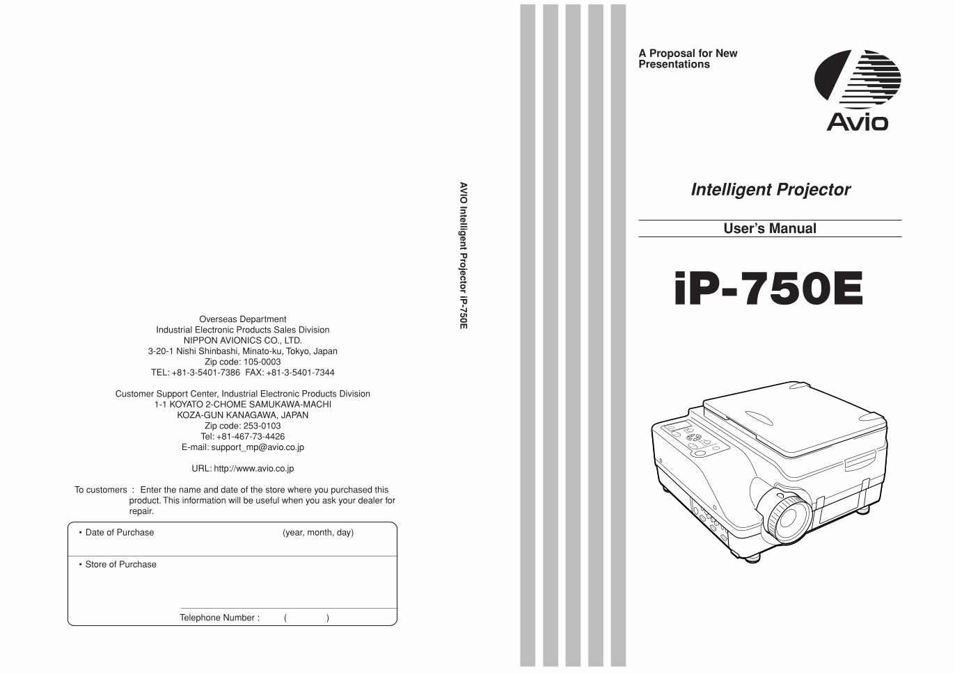
A Proposal for NewPresentations
Intelligent Projector
User’s Manual
iP-750E
3
Thank you for your purchase of an AVIO product.
Please read this manual carefully in order to use the projector properly.
After reading this, please keep it in a safe place together with the warranty sheet.
Features of the iP-750E• Very versatile five-in-one projector. A projector for the multimedia age.
1. Projection of documents, catalogs, and other printed materials. Printed materials can be projected directly without the
creation of OHP film.
2. Projection of personal computer screen images
Detailed presentations can be made using a personal computer.
3. The video images of video tape decks, DVDs and other equipment can be projected. This permits the creation of presen-
tations that are visually appealing.
4. Projection images can be imported to a personal computer connected via USB.
5. An image that has been scanned to a personal computer can be written on as one pleases using a tablet or another device
and while doing so the image can be projected.
• Easily understood, simple operation for everyone
One button operation simply switches the projection of printed material, personal computer screen, and video image.
• Designed for a conservation of resources which offers excellent cost performance
The creation of OHP film is not required. This allows a reduction of wasteful time and costs.
• Expressive color pictures
High resolution, 2 million pixel CCD camera is built in. It provides faithful and clear reproduction of the detailed neutral tones of
color documents with its full-color 16.77 million colors.
• Enlarged display without changing the screen size
When projecting documents having small characters that were not created for presentations, such as catalogs and word-
processed documents, the iP-750E can enlarge the document without changing the screen size to provide an easy-to-view
display.
• Provided with display functions for compressed or enlarged PC screen
Screens of resolution more than 1024 768 dots are displayed compressed to 1024 768 dots without any loss in character
quality. Such as 640 480 resolution screens can also be enlarged to 1024 768 dots.
About TrademarksIBM and PC/AT are trademarks or registered trademarks of International Business
Machines Corporation.
Macintosh and Power Book are trademarks of Apple Computer Inc.
Windows is a trademark of U.S. Microsoft Corporation.
Warnings and Safety PrecautionsWarning Symbols
To alert the user to important safety precautions, the following symbols are used
in this manual and on the product. Make sure you understand what these sym-
bols mean before operating the projector.
WARNING Death or serious injury may result if this warning is ignored.
CAUTION Injury or damage to the equipment may result if this warning is ignored.
NOTE This indicates an item that you should take care of when handling your projector.
This symbol alerts the user to high voltage that could cause electric shock.
4
WARNING
If a fault occurs:
• If you detect smoke, or a strange smell or sound, immediately disconnect the power cable.
It is dangerous to continue using the projector after a fault occurs. Return the projector to the dealer where it was purchased
for repair.
Avoid placing the projector near dangerous substances.
• Make sure that no metallic or flammable material can get into the projector through the air vents.
• Do not place any objects containing water on top of or next to the projector.
If foreign matter gets inside the projector:
• If foreign matter such as water or metal gets inside, immediately disconnect the power cable.
It is dangerous to continue using the projector when foreign matter gets inside. Return the projector to the dealer where it
was purchased for servicing.
Do not remove the cabinet.
• Do not remove the cabinet. There are high-voltage components inside and touching these parts could cause electric shock,
or damage the equipment.
Handle the power cable safely.
• Do not place any heavy objects on top of the power cable.
Damage to the power cable can cause wire breakage, fire, or electric shock.
• Do not pull the power cable when disconnecting the power plug.
Pulling the cable may break the wires or cause fire or electric shock. Always hold the plug itself when pulling it out of the
power outlet.
• Do not damage the power cable. If the power cable is damaged (e.g. the core is exposed or cut), contact the sales office of
purchase. (charged) it could cause fire or electric shock if you continue using the damaged power cable.
• Do not peep into the lens.
• Do not peep into the lens of the projector during operation. The powerful rays passing through the lens could damage the
eyes.
• Do not put the projector in unstable places.
• Do not put the projector in unstable places such as on unstable desks or slopes.
Doing so could cause the projector to drop or turn over, resulting in injury.
• Do not use any voltages other than specified.
• Do not use any voltages other than specified. Doing so could cause fire or electric shock.
• Do not beat the glass surface
• Do not beat the glass surface over the scanner. Doing so may break the glass, resulting in injury.
• Do not touch the air vents or lamp cover
• The air vents, lamp cover, and peripheral surfaces may be high temperature during operation or just after the light is turned
off.
Do not touch those for a long time.
• Do not block the lens front
• Do not block the lens front during operation.
The powerful rays passing through the lens may cause fire or burns if you put anything in front of the lens or block the lens
with your hand during operation.
Safety Precautions
5
CAUTION
• Installation
• Avoid installing the projector in places where it may be exposed to:
- Strong vibrations
- Soot or steam
- Direct sunlight or near a heater (35°C/95°F or higher)
- High humidity or dust
- Extreme cold (0°C/32°F or lower)
- Strong magnetic or electric field generated from a nearby appliance
- Wobbling on an unstable surface
• Do not block the air vents.
• Do not block the air vents with cloth or an object.
When you put anything around the unit, be sure to ensure a space of 10 cm/4 inches or more between the unit and the air
vent. Be sure to prevent paper or cloth from blocking the air vent at the bottom of the unit. If blocked, the internal temperature
may increase, resulting in malfunctions.
• Do not bump the projector.
• Avoid bumping the projector when moving or handling. Shocks can cause damage.
• Care of the projector
• To prevent risk of accidents, always disconnect the power plug before cleaning the projector.
• Clean the lens surface with a commercial blower or lens cleaning paper.
Wiping with tissue paper or a handkerchief can damage the lens.
• To clean the cabinet, operation panel, and glass surface, wipe gently with a soft cloth. For particularly dirty spots, soak the
cloth in a neutral detergent mixed in water, wring out well and wipe off the dirt, then use a dry cloth to wipe dry.
• Do not wipe the projector with any volatile solvent such as benzine or thinner.
Solvents can cause surface deformation or flaking of the paint.
If using an impregnated cloth, follow the instructions of the cloth.
• Avoid scratching the glass surface.
• Take care not to scratch the glass surface of the scanner with hard or pointed objects.
Scratches on the glass may distort the projected image.
• Battery
• When inserting battery in the remote control, note the polarity (plus and minus signs) and insert correctly as indicated.
Inserting a battery in a wrong direction can cause rupture or leakage, and could result in fire and injury or soil the surround-
ing area.
• Do not use coin battery other than the type specified for the equipment. Incorrect battery usage could result in rupture or
leakage, and could cause fire and injury.
• Do not heat, break open, burn, or immerse the battery. Battery rupture or leakage could cause fire and injury.
• Servicing and cleaning
• Have the internal components cleaned by a retailer about once a year. There is a risk of fire or faulty operation if the inside
of the projector gets dusty and is not cleaned for a long time. For best results, the projector should be serviced before the wet
season brings damp conditions. Cleaning charges are at the discretion of the retailer.
• If not using the projector for a long period:
• If you do not plan to use the projector for a long time, disconnect the power cord for safety.
• Disposal
• Follow the recommendations of your local authority when disposing of the projector.
• Transporting the projector
• Use the special packaging when transporting the projector. The manufacturer cannot accept responsibility in the event of
damage or accident if other packaging is used.
• Use the special packaging no more than two times. Repeated usage reduces the shock absorbency of the packaging and
can lead to damage or accident.
• Contact the retailer if you require new packaging.
Safety Precautions
6
• Lamp implosion
• A DC type Super High pressure lamp is used in this projector and it is rare for the lamp to explode during use. The unit is also
designed to forcibly turn off the lamp because there is a high possibility that the lamp will break if it is used beyond the lamp
usage of 2000 hours (Refer to pages 43 and 45).
Note the following things• A sound occurs because the internal pressure of the Super High pressure lamp gets extremely high.
The unit is designed so that no pieces of glass come out of it when the lamp explodes.
• However, the gas inside of the lamp can escape and looks like white smoke.
It will not cause any fire.
Remedy• If a lamp explodes in a product, there will be pieces of lamp inside. Do not replace the lamp. Return the product to the sales
office or agent of purchase.
Even though the lamp has exploded, never try to replace the lamp by yourself. The lamp pieces could cause injury.
• Replacing the lamp
• Be sure to turn the lamp off and disconnect the power cable when the fan stops, and wait an hour or more before replacing
the lamp.
Replacing the lamp during operation or just after the power is turned off may cause burns due to heat.
Refer to “Lamp Unit Replacement” on page 43 for the procedure.
• Replacing / cleaning the air filter
• Be sure to disconnect the power cable when the cooling fan stops before removing the air filter.
Removing the air filter while the cooling fan is rotating could cause a accident.
Refer to “Cleaning the Air Filter” on page 46 for the procedure.
• Avoiding malfunctions and accidents
• Adjust the Adjustable feet to keep the projector horizontally.
Using the projector in a tilted status may cause injury if it rolls over. Refer to
“Adjusting the Tilt” on page 23 for the adjusting procedure.
• Do not do the followings
• Do not put anything heavy on the projector.
• Do not step on the projector, rack, or stand. Do not hold or hang on the projector.
Doing so could cause the projector to roll over or break, resulting in injury.
Especially be careful if small children are near.
• Do not use the rack unless the casters are locked when placing the projector on a rack with casters.
Doing so may cause the projector to move or roll over, resulting in injury.
• Do not turn the lamp on/off within one minute after it is turned off/on. Extremely high voltage is generated in the lamp just
after it is turned on. Turning the lamp on/off too frequently could cause the lamp to deteriorate or break, resulting in malfunc-
tions of the projector.
• Do not project an image with the lens cap attached.
• Moving the projector
• Be sure careful of the glass surface at moving the projector while holding the handles.
• If the document cover is not inserted enough, it may get loose and fall off while you carry it.
• Care of the power cable and plug
• Do not put the power cable near a heater.
Doing so could cause the sheath of the cable to melt down, resulting in fire or electric shock.
• Do not connect or disconnect the power cable with wet hands. Doing so could cause electric shock.
• Be sure to pull out the power cable and disconnect any cable connections between units and release the anti-theft lock
before moving the projector.
Moving the projector with cables connected may cause fire or electric shock if the cables are damaged.
• If you do not plan to use the projector for a long time, disconnect the power cable for safety.
• DO NOT REMOVE ANY SCREWS except the lamp cover screw and two lamp unit screws. Otherwise you could receive
an electric shock.
• Light Polarizing Element
Light polarizing elements such as the light source lamp and the liquid crystal panel are parts that have a service life. When
used for a long time, repair and replacement will be necessary. Please contact a customer support center for details.
Safety Precautions
7
Table of Contents
Safety Precautions .................................................... 3
A Check of the Supplied Itemsand the Names of the Parts ................................. 8
Supplied Parts Check .................................................. 8Names and Functions of the Parts (Projector) ............ 9Names and Functions of the Parts (Input Connectors) .............. 11Names and Functions of the Parts (Operation Panel) ............... 12Names and Functions of the Parts (Remote Control) ................ 13Operation of the Remote Control .............................. 14Battery Replacement ................................................ 14
Procedure Up to Projection .................................... 15
Projection Distance and Screen Size .................... 16
Connections with the Personal Computer ...................... 17Basic Connections .................................................... 17Connections with Personal Computers ..................... 18Personal Computer Input Connector ......................... 18When the Image of the Personal Computer
Screen Is Not Projected ....................................... 19Table of Supported Input Signals
(Personal Computer Video Input Connector) ....... 20
Connections with Video Equipment ...................... 21
Connection of the Power Cable andOn/Off Switching ................................................ 22
Switch On the Power ................................................. 22Switch Off the Power ................................................. 22
Adjustment of the Projection Image ...................... 23Adjusting the Projection Image ................................. 23Making Focus/Zoom Adjustments ............................. 23Adjusting the Tilt (Slant) ............................................ 23
Regular Operation ................................................... 24Select the Input ......................................................... 24Changing the Orientation of the Projection Image .... 24Enlarging and Reducing the Projection Image .......... 25Adjusting the size of the projected image ................. 26Adjusting the Brightness ........................................... 27Capturing the Projection Image/ Still Image Display ......... 27
Viewing OHP History Images .................................... 28
Transferring Captured Images ................................... 29Adjusting the Volume................................................. 29Displaying the Pointer ............................................... 30Deleting the Projection Image and Audio .................. 30
Method of OHP Operation ...................................... 31Attaching the Document Cover ................................. 31Preparation of the Projection Document ................... 31Reading Size of Projection Documents ..................... 31
Menu Configuration ................................................ 32
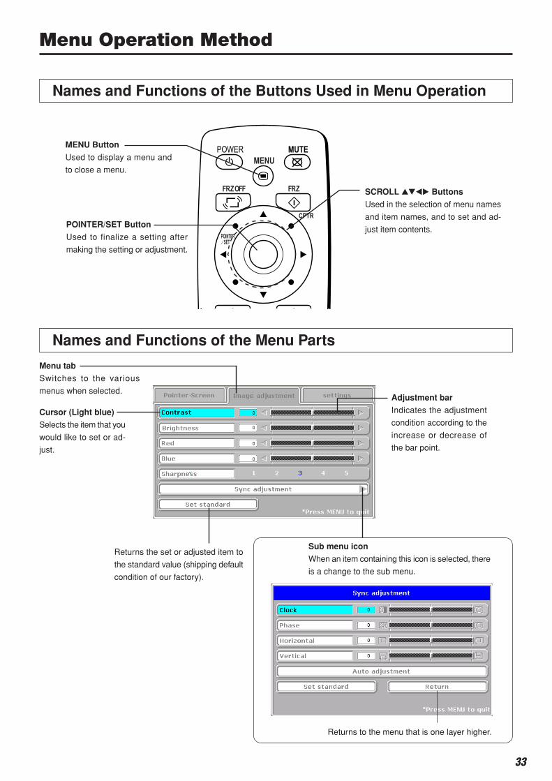
Menu Operation Method ......................................... 33Names and Functions of the Buttons
Used in Menu Operation ................................. 33Names and Functions of the Menu Parts .................. 33Method of Menu Operation ....................................... 34
Menu Description .................................................... 36Pntr setting ................................................................ 36Image adjustment ...................................................... 36Settings ..................................................................... 38
Maintenance ............................................................ 41Fault Protection ......................................................... 41Replacement of the Lamp Unit .................................. 43Cleaning the Air Filter ................................................ 46
Troubleshooting ...................................................... 47
Warranty & Repair Service ..................................... 48
Specifications .......................................................... 49
8
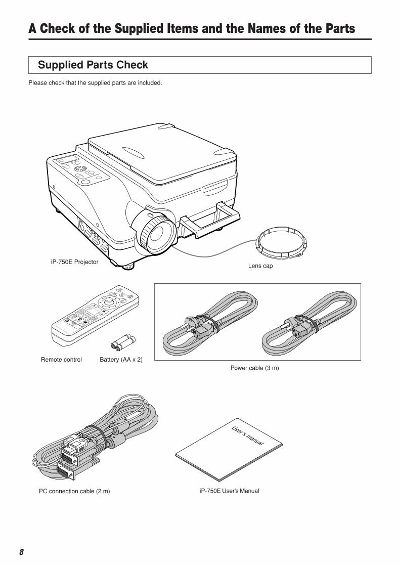
User's manual
A Check of the Supplied Items and the Names of the Parts
Supplied Parts Check
Please check that the supplied parts are included.
Lens capiP-750E Projector
Power cable (3 m)Remote control
iP-750E User’s ManualPC connection cable (2 m)
Battery (AA x 2)

9
Document cover
The document or printed material to be read is placed un-
der this cover.
See Page 31.Operation panel
The buttons used for regu-
lar operation are located
here. See Page 12.
Air Vent A (air filter)
(side of main unit)
Air is taken in through this vent. An air filter is provided to
prevent dust from getting inside the projector.
See page 46.
Tilt adjustment lever
Press here to adjust the tilt foot. See Page 23.
Tilt foot
This foot is used to adjust the vertical angle of the
projection as well as the left-right balance. Turning
it to the left extends it and turning it to the right
shortens it. See Page 23.
Zoom lever
Turn this to adjust the screen size. See Page 23.
Projection lensThe image is projected from here.* Be sure to remove the lens cap before projecting.
Focus adjustment ring
Turn this to adjust the focus.
See Page 23.
Tilt foot
Remote control IR sensor
A Check of the Supplied Items and the Names of the Parts
Names and Functions of the Parts (Projector)
Handle
Tilt foot
Input connector panel
The connectors for the personal com-
puter, video, and other connections
are located here.
See Page 11.
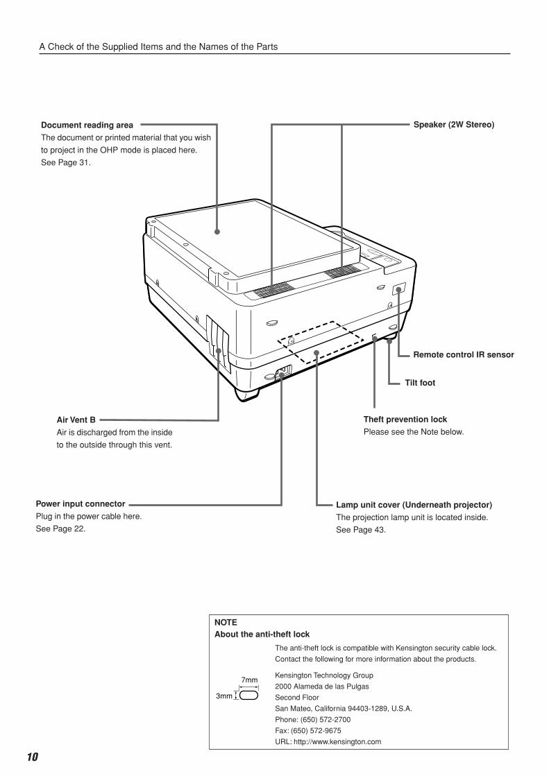
10
Power input connector
Plug in the power cable here.
See Page 22.
Speaker (2W Stereo)
Tilt foot
Lamp unit cover (Underneath projector)
The projection lamp unit is located inside.
See Page 43.
Remote control IR sensor
Air Vent B
Air is discharged from the inside
to the outside through this vent.
Document reading area
The document or printed material that you wish
to project in the OHP mode is placed here.
See Page 31.
A Check of the Supplied Items and the Names of the Parts
Theft prevention lock
Please see the Note below.
NOTEAbout the anti-theft lock
The anti-theft lock is compatible with Kensington security cable lock.
Contact the following for more information about the products.
Kensington Technology Group
2000 Alameda de las Pulgas
Second Floor
San Mateo, California 94403-1289, U.S.A.
Phone: (650) 572-2700
Fax: (650) 572-9675
URL: http://www.kensington.com
7mm
3mm
11
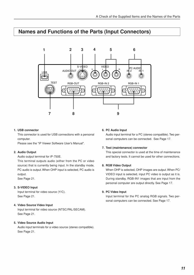
Names and Functions of the Parts (Input Connectors)
1 2 3 5 6
7 8 9
4
A Check of the Supplied Items and the Names of the Parts
1. USB connector
This connector is used for USB connections with a personal
computer.
Please see the "iP Viewer Software User's Manual".
2. Audio Output
Audio output terminal for iP-750E.
This terminal outputs audio (either from the PC or video
source) that is currently being input. In the standby mode,
PC audio is output. When OHP input is selected, PC audio is
output.
See Page 21.
3. S-VIDEO Input
Input terminal for video source (Y/C).
See Page 21.
4. Video Source Video Input
Input terminal for video source (NTSC/PAL/SECAM).
See Page 21.
5. Video Source Audio Input
Audio input terminals for a video source (stereo compatible).
See Page 21.
6. PC Audio Input
Audio input terminal for a PC (stereo compatible). Two per-
sonal computers can be connected. See Page 17.
7. Test (maintenance) connector
This special connector is used at the time of maintenance
and factory tests. It cannot be used for other connections.
8. RGB Video Output
When OHP is selected, OHP images are output. When PC/
VIDEO input is selected, input PC video is output as it is.
During standby, RGB-IN1 images that are input from the
personal computer are output directly. See Page 17.
9. PC Video Input
Input terminal for the PC analog RGB signals. Two per-
sonal computers can be connected. See Page 17.
12
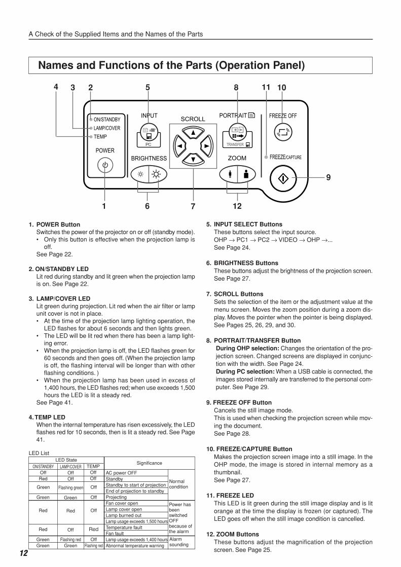
Names and Functions of the Parts (Operation Panel)
1 7
5
12
8 104 3 2
9
A Check of the Supplied Items and the Names of the Parts
5. INPUT SELECT ButtonsThese buttons select the input source.OHP → PC1 → PC2 → VIDEO → OHP →...See Page 24.
6. BRIGHTNESS ButtonsThese buttons adjust the brightness of the projection screen.See Page 27.
7. SCROLL ButtonsSets the selection of the item or the adjustment value at themenu screen. Moves the zoom position during a zoom dis-play. Moves the pointer when the pointer is being displayed.See Pages 25, 26, 29, and 30.
8. PORTRAIT/TRANSFER ButtonDuring OHP selection: Changes the orientation of the pro-jection screen. Changed screens are displayed in conjunc-tion with the width. See Page 24.During PC selection: When a USB cable is connected, theimages stored internally are transferred to the personal com-puter. See Page 29.
9. FREEZE OFF ButtonCancels the still image mode.This is used when checking the projection screen while mov-ing the document.See Page 28.
10. FREEZE/CAPTURE ButtonMakes the projection screen image into a still image. In theOHP mode, the image is stored in internal memory as athumbnail.See Page 27.
11. FREEZE LEDThis LED is lit green during the still image display and is litorange at the time the display is frozen (or captured). TheLED goes off when the still image condition is cancelled.
12. ZOOM ButtonsThese buttons adjust the magnification of the projectionscreen. See Page 25.
1. POWER ButtonSwitches the power of the projector on or off (standby mode).• Only this button is effective when the projection lamp is
off.See Page 22.
2. ON/STANDBY LEDLit red during standby and lit green when the projection lampis on. See Page 22.
3. LAMP/COVER LEDLit green during projection. Lit red when the air filter or lampunit cover is not in place.• At the time of the projection lamp lighting operation, the
LED flashes for about 6 seconds and then lights green.• The LED will be lit red when there has been a lamp light-
ing error.• When the projection lamp is off, the LED flashes green for
60 seconds and then goes off. (When the projection lampis off, the flashing interval will be longer than with otherflashing conditions. )
• When the projection lamp has been used in excess of1,400 hours, the LED flashes red; when use exceeds 1,500hours the LED is lit a steady red.
See Page 41.
4. TEMP LEDWhen the internal temperature has risen excessively, the LEDflashes red for 10 seconds, then is lit a steady red. See Page41.
LED ListLED State
Significance
AC power OFFStandbyStandby to start of projectionEnd of projection to standbyProjectingFan cover openLamp cover openLamp burned outLamp usage exceeds 1,500 hoursTemperature faultFan faultLamp usage exceeds 1,400 hoursAbnormal temperature warning
Normalcondition
Alarmsounding
Power hasbeenswitchedOFFbecause ofthe alarm
TEMPOffOff
Off
Off
Off
Red
OffFlashing red
LAMP/COVEROffOff
Flashing green
Green
Red
Off
Flashing redGreen
ON/STANDBYOffRed
Green
Green
Red
Red
GreenGreen
6
11
13
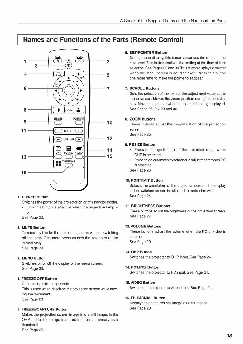
Names and Functions of the Parts (Remote Control)
1. POWER ButtonSwitches the power of the projector on or off (standby mode).• Only this button is effective when the projection lamp is
off.See Page 22.
2. MUTE ButtonTemporarily blanks the projection screen without switchingoff the lamp. One more press causes the screen to returnimmediately.See Page 30.
3. MENU ButtonSwitches on or off the display of the menu screen.See Page 33.
4. FREEZE OFF ButtonCancels the still image mode.This is used when checking the projection screen while mov-ing the document.See Page 28.
5. FREEZE/CAPTURE ButtonMakes the projection screen image into a still image. In theOHP mode, the image is stored in internal memory as athumbnail.See Page 27.
6. SET/POINTER ButtonDuring menu display, this button advances the menu to thenext level. This button finalizes the setting at the time of itemselection. See Pages 30 and 33. This button displays a pointerwhen the menu screen is not displayed. Press this buttonone more time to make the pointer disappear.
7. SCROLL ButtonsSets the selection of the item or the adjustment value at themenu screen. Moves the zoom position during a zoom dis-play. Moves the pointer when the pointer is being displayed.See Pages 25, 26, 29 and 30.
8. ZOOM ButtonsThese buttons adjust the magnification of the projectionscreen.See Page 25.
9. RESIZE Button• Press to change the size of the projected image when
OHP is selected.• Press to do automatic synchronous adjustments when PC
is selected.See Page 26.
10. PORTRAIT ButtonSelects the orientation of the projection screen. The displayof the switched screen is adjusted to match the width.See Page 24.
11. BRIGHTNESS ButtonsThese buttons adjust the brightness of the projection screen.See Page 27.
12. VOLUME ButtonsThese buttons adjust the volume when the PC or video isselected.See Page 29.
13. OHP ButtonSwitches the projector to OHP input. See Page 24.
14. PC1/PC2 ButtonSwitches the projector to PC input. See Page 24.
15. VIDEO ButtonSwitches the projector to video input. See Page 24.
16. THUMBNAIL ButtonDisplays the captured still image as a thumbnail.See Page 28.
1
4
6
8
9
11
13
16
2
10
12
5
3
1415
7
A Check of the Supplied Items and the Names of the Parts
14
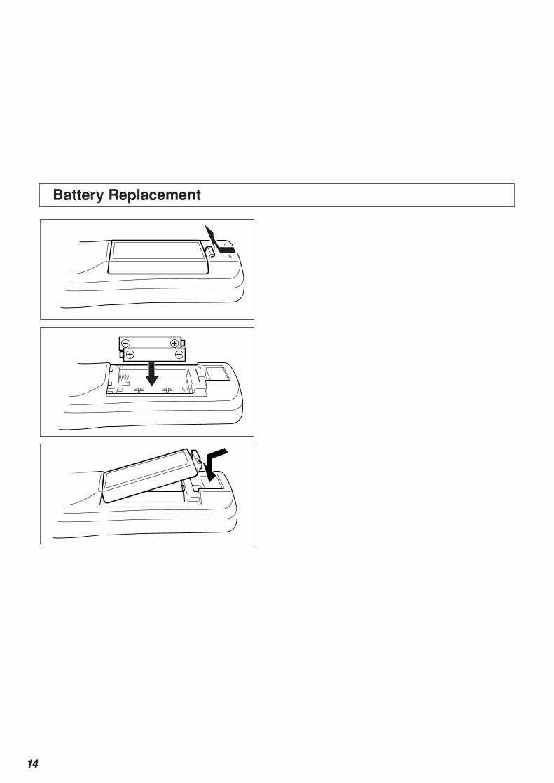
Battery Replacement
A Check of the Supplied Items and the Names of the Parts
Operation of the Remote Control• Please use the remote control within a range of about 7 m from the remote control IR sensor of the projector (located at both
the front and rear) and within an angle of 10 degrees to the left and 10 degrees to the right. Note that this distance may be
shorter depending on battery consumption.
• The remote control will not function when there is an obstacle located between the remote control and the remote control IR
sensor of the projector.
1.Remove the battery compartment cover by
pushing in the claw and lifting the cover up.
2. Install two batteries in the battery compart-
ment, making sure that they are aligned as in-
dicated by the (+) and (–) marks.
3.Return the battery compartment cover to its
original position.
Handling of the Remote Control• Do not subject the remote controller to such severe impact as dropping it on the floor. Doing so may
damage it and cause it to cease functioning.• Keep the remote sensor away from water. Wipe the remote controller immediately if it gets wet.• Avoid heat or hot water. Remove the dry cells when you are not using the remote controller for a long
period of time.• Do not mix new and old dry cells, or use different types of dry cells at the same time.• Do not disassemble or heat batteries, or throw them into a fire.• Follow your local government's disposal instructions for used dry cells.• The remote controller may not work when it is used near inverter-driven equipment.• The remote controller may not work or may work ineffectively when it is used near inverter-driven fluo-
rescent lighting.• Please handle the remote control with care, since there are some operations available only with it.
CAUTION
NOTE:
• When replacing the batteries, buy AA batteries.
• Ni-Cad batteries or other chargeable batteries cannot be used. Use manganese batteries or alkaline batteries.
15
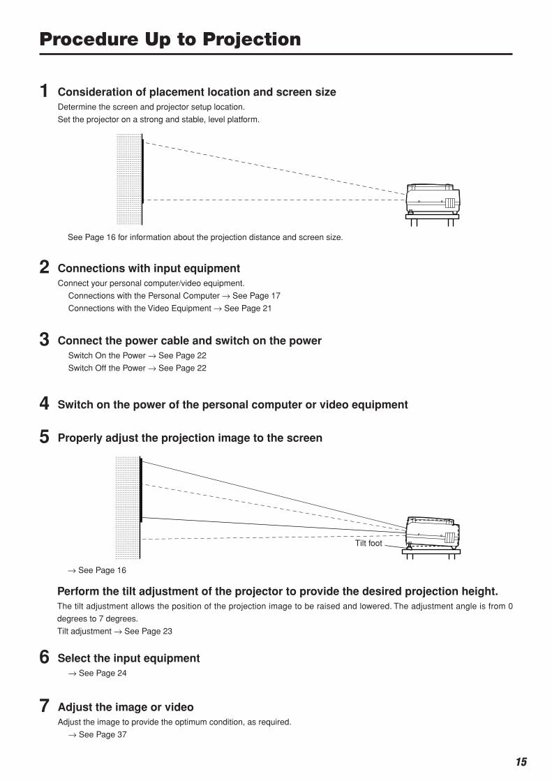
Procedure Up to Projection
1 Consideration of placement location and screen sizeDetermine the screen and projector setup location.
Set the projector on a strong and stable, level platform.
2 Connections with input equipmentConnect your personal computer/video equipment.
Connections with the Personal Computer → See Page 17
Connections with the Video Equipment → See Page 21
3 Connect the power cable and switch on the powerSwitch On the Power → See Page 22
Switch Off the Power → See Page 22
4 Switch on the power of the personal computer or video equipment
5 Properly adjust the projection image to the screen
6 Select the input equipment→ See Page 24
7 Adjust the image or videoAdjust the image to provide the optimum condition, as required.
→ See Page 37
Perform the tilt adjustment of the projector to provide the desired projection height.The tilt adjustment allows the position of the projection image to be raised and lowered. The adjustment angle is from 0
degrees to 7 degrees.
Tilt adjustment → See Page 23
See Page 16 for information about the projection distance and screen size.
→ See Page 16
Tilt foot
16
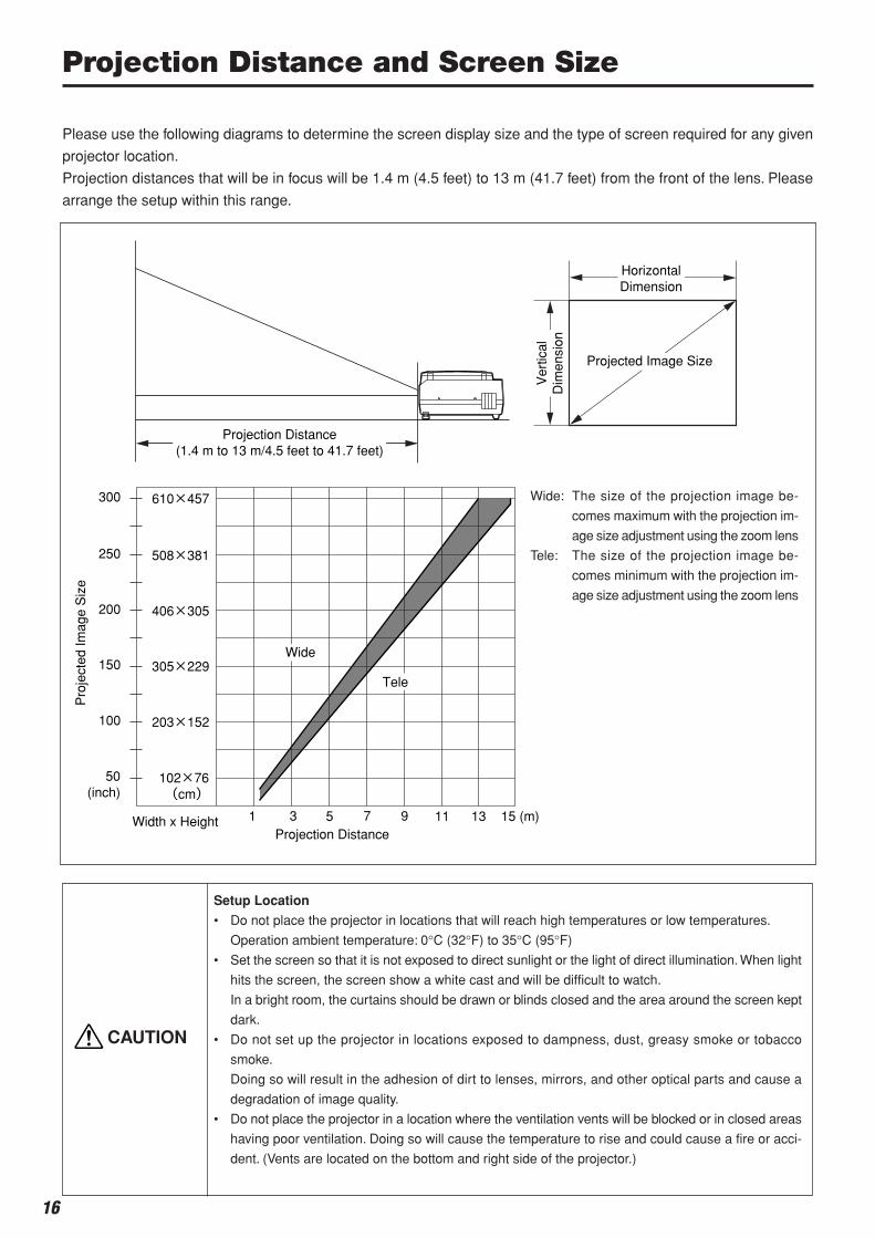
Please use the following diagrams to determine the screen display size and the type of screen required for any given
projector location.
Projection distances that will be in focus will be 1.4 m (4.5 feet) to 13 m (41.7 feet) from the front of the lens. Please
arrange the setup within this range.
HorizontalDimension
Ver
tical
Dim
ensi
on250
300
200
150
100
50(inch)
1 3 5 7 9 11 13 15 (m)
Projected Image Size
Width x Height
Pro
ject
ed Im
age
Siz
e
Projection Distance
508×381
610×457
406×305
305×229
203×152
102×76(cm)
Tele
Wide
Projection Distance(1.4 m to 13 m/4.5 feet to 41.7 feet)
Projection Distance and Screen Size
Wide: The size of the projection image be-
comes maximum with the projection im-
age size adjustment using the zoom lens
Tele: The size of the projection image be-
comes minimum with the projection im-
age size adjustment using the zoom lens
Setup Location
• Do not place the projector in locations that will reach high temperatures or low temperatures.
Operation ambient temperature: 0°C (32°F) to 35°C (95°F)
• Set the screen so that it is not exposed to direct sunlight or the light of direct illumination. When light
hits the screen, the screen show a white cast and will be difficult to watch.
In a bright room, the curtains should be drawn or blinds closed and the area around the screen kept
dark.
• Do not set up the projector in locations exposed to dampness, dust, greasy smoke or tobacco
smoke.
Doing so will result in the adhesion of dirt to lenses, mirrors, and other optical parts and cause a
degradation of image quality.
• Do not place the projector in a location where the ventilation vents will be blocked or in closed areas
having poor ventilation. Doing so will cause the temperature to rise and could cause a fire or acci-
dent. (Vents are located on the bottom and right side of the projector.)
CAUTION
17
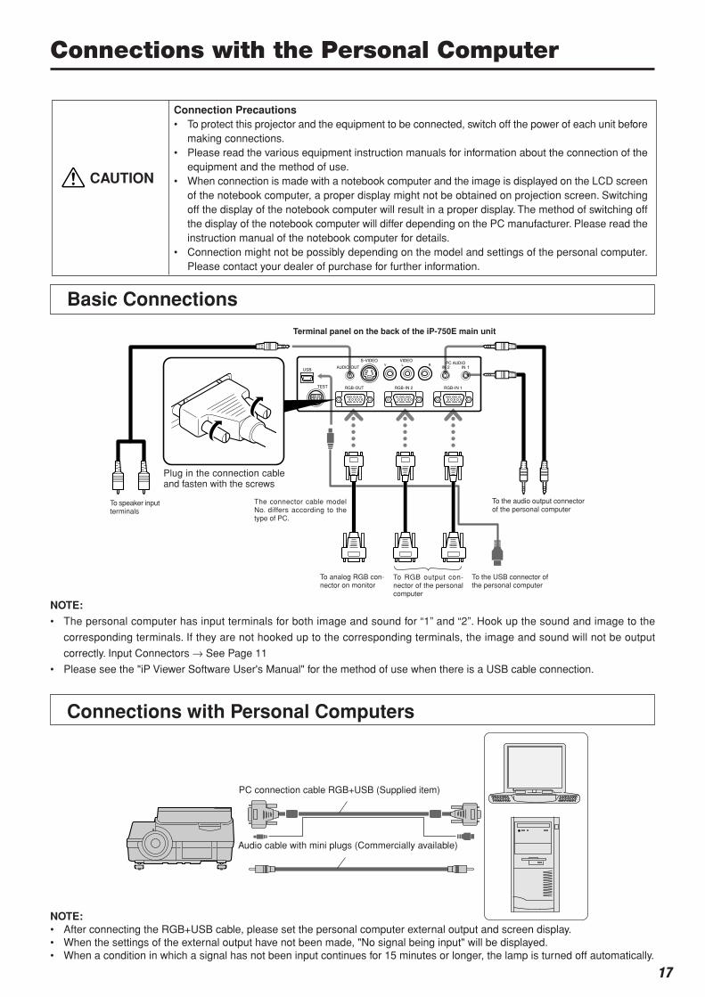
Connections with the Personal Computer
Connections with Personal Computers
NOTE:
• The personal computer has input terminals for both image and sound for “1” and “2”. Hook up the sound and image to the
corresponding terminals. If they are not hooked up to the corresponding terminals, the image and sound will not be output
correctly. Input Connectors → See Page 11
• Please see the "iP Viewer Software User's Manual" for the method of use when there is a USB cable connection.
Connection Precautions• To protect this projector and the equipment to be connected, switch off the power of each unit before
making connections.• Please read the various equipment instruction manuals for information about the connection of the
equipment and the method of use.• When connection is made with a notebook computer and the image is displayed on the LCD screen
of the notebook computer, a proper display might not be obtained on projection screen. Switchingoff the display of the notebook computer will result in a proper display. The method of switching offthe display of the notebook computer will differ depending on the PC manufacturer. Please read theinstruction manual of the notebook computer for details.
• Connection might not be possibly depending on the model and settings of the personal computer.Please contact your dealer of purchase for further information.
CAUTION
Basic Connections
To the USB connector ofthe personal computer
Plug in the connection cableand fasten with the screws
To RGB output con-nector of the personalcomputer
To analog RGB con-nector on monitor
The connector cable modelNo. differs according to thetype of PC.
To the audio output connectorof the personal computer
To speaker inputterminals
Terminal panel on the back of the iP-750E main unit
PC connection cable RGB+USB (Supplied item)
Audio cable with mini plugs (Commercially available)
NOTE:• After connecting the RGB+USB cable, please set the personal computer external output and screen display.• When the settings of the external output have not been made, "No signal being input" will be displayed.• When a condition in which a signal has not been input continues for 15 minutes or longer, the lamp is turned off automatically.
18
Personal Computer Input ConnectorThe personal computer input connector uses a 15-pin mini D-SUB type connector.
The pins and their corresponding signal inputs are described below.
Personal Computer Input Connector
5 4 3 2 1
10 9 8 7 6
15 14 13 12 11
NOTE:
• This projector uses a 15-pin RGB input and an analog type output terminals. For this reason, it cannot be connected to
a digital output type personal computer.
• Plug and play is not supported.
y GND
u GND
i GND
o NC
!0 GND
!1 NC
!2 Pull up (+5V)
!3 H.SYNC
!4 V.SYNC
!5 Pull up (+5V)
q RED VIDEO
w GREEN VIDEO
e BLUE VIDEO
r GND
t NC
Connecting Macintosh Computers• Attach the supplied (RGB+USB) cable if when the monitor output is a VGA port (mini D-SUB 15-pin).
• An optional Apple video adapter cable is required when the monitor output is a video port or DVI port.
• Please do not make a USB connection because iP Viewer does not support the Macintosh.
Connections with the Personal Computer

19
Connections with the Personal Computer
Please check the matters described below when the image of the personal computer is not projected or when there is
projection but the image is not correct.
The image is not projectedWhen the external output signal from the personal computer is not input to the iP-750E, "No signal being input" is displayed on the
display screen of the iP-750E. Should this occur, please check the following matters.
1 Try restarting the personal computer.
When the iP-750E is connected after the personal computer has been started, the connection of the iP-750E might not be
recognized by the personal computer. When the iP-750E has not been recognized, the external output signal from the personal
computer will not be output and there will not be an image to project.
2 Check the functions of the personal computer.
Depending on the notebook computer, some computers will require an operation to output a signal from the external output
connector. If this operation is not performed, the external output signal from the notebook computer will not be output.
Please see the instruction manual of the notebook computer you are using and perform the operation that will output the signal
from the external output connector.
(Operation Example)
IBM PC/AT and DOS/V computers:
Press the [Fn] key + "any one of the [F1] to [F12] keys (noting that the operation will differ depending on the model)"
PC98 notebook computers later than the Nr Series (with the exception of the PC-98NX):
Press the "Suspend Resume" switch.
Correspondence List for Connection Problems with the Personal
When the Image of the Personal Computer Screen Is Not Projected
The screen of the personal computer is correct, but the image is not projected properlyPlease check the functions of the personal computer.
Even though the LCD screen of the notebook computer is properly displayed, the projected image might not be projected
properly. Due to restrictions of the notebook computer there will rarely be instances in which the setting of a simultaneous
display (i.e., simultaneous output of the external output signal while displaying the screen of the personal computer) will result
in a signal that greatly deviates from the range supported by the iP-750E and proper projection will not be possible.
Should this occur, a proper image will not be obtained even when adjustments are made with the iP-750E.
In some instances, the personal computer screen will be properly projected by the iP-750E when the simultaneous display is
cancelled and an operation is performed to output only the external output signal. Please see the instruction manual of the
notebook computer you are using for details.
When a moving image is displayed on a portion of the screen, it is possible that a portion of the moving image only is displayed
black. Should this occur, please read the instruction manual of the personal computer carefully and set the personal computer
accordingly.
Manufacturer External Output Switching Method Manufacturer External Output Switching MethodIBM Fn+f7 DELL Fn+f8NEC Parallel output Toshiba Fn+f5
Switching from the Task Bar Panasonic Fn+f3Fn+f3 Fujitsu Fn+f10
COMPAQ Fn+f4 Mitsubishi Fn+f5Sharp Fn+f5 Apple Control panelSONY Fn+f7 → monitor display switching
* This table indicates the results of an independent investigation by us of representative computers made
by various manufacturers; it does not include all of the connections.
* Company names and product names mentioned are the trade marks or registered trademarks of the
respective companies.
20
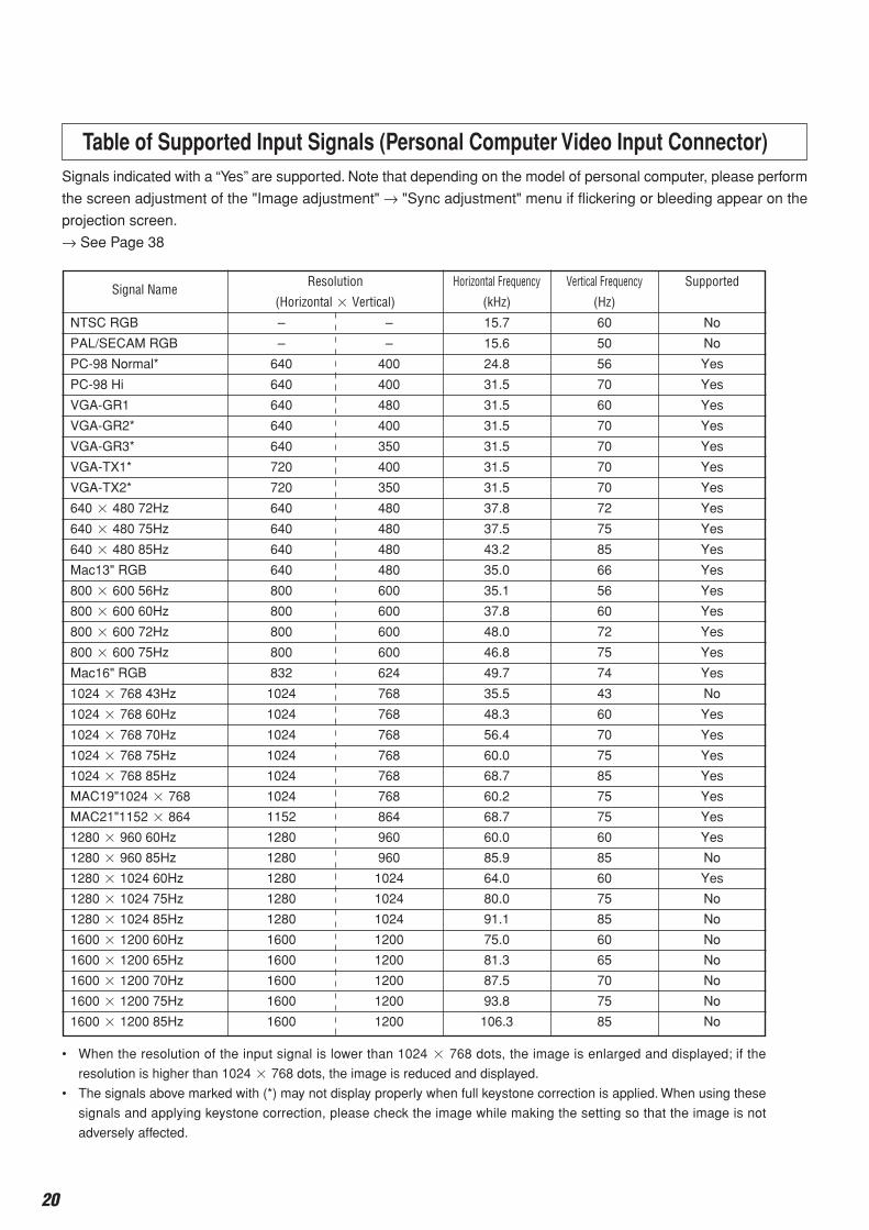
Signal NameResolution Horizontal Frequency Vertical Frequency Supported
(Horizontal Vertical) (kHz) (Hz)
NTSC RGB – – 15.7 60 No
PAL/SECAM RGB – – 15.6 50 No
PC-98 Normal* 640 400 24.8 56 Yes
PC-98 Hi 640 400 31.5 70 Yes
VGA-GR1 640 480 31.5 60 Yes
VGA-GR2* 640 400 31.5 70 Yes
VGA-GR3* 640 350 31.5 70 Yes
VGA-TX1* 720 400 31.5 70 Yes
VGA-TX2* 720 350 31.5 70 Yes
640 480 72Hz 640 480 37.8 72 Yes
640 480 75Hz 640 480 37.5 75 Yes
640 480 85Hz 640 480 43.2 85 Yes
Mac13" RGB 640 480 35.0 66 Yes
800 600 56Hz 800 600 35.1 56 Yes
800 600 60Hz 800 600 37.8 60 Yes
800 600 72Hz 800 600 48.0 72 Yes
800 600 75Hz 800 600 46.8 75 Yes
Mac16" RGB 832 624 49.7 74 Yes
1024 768 43Hz 1024 768 35.5 43 No
1024 768 60Hz 1024 768 48.3 60 Yes
1024 768 70Hz 1024 768 56.4 70 Yes
1024 768 75Hz 1024 768 60.0 75 Yes
1024 768 85Hz 1024 768 68.7 85 Yes
MAC19"1024 768 1024 768 60.2 75 Yes
MAC21"1152 864 1152 864 68.7 75 Yes
1280 960 60Hz 1280 960 60.0 60 Yes
1280 960 85Hz 1280 960 85.9 85 No
1280 1024 60Hz 1280 1024 64.0 60 Yes
1280 1024 75Hz 1280 1024 80.0 75 No
1280 1024 85Hz 1280 1024 91.1 85 No
1600 1200 60Hz 1600 1200 75.0 60 No
1600 1200 65Hz 1600 1200 81.3 65 No
1600 1200 70Hz 1600 1200 87.5 70 No
1600 1200 75Hz 1600 1200 93.8 75 No
1600 1200 85Hz 1600 1200 106.3 85 No
• When the resolution of the input signal is lower than 1024 768 dots, the image is enlarged and displayed; if the
resolution is higher than 1024 768 dots, the image is reduced and displayed.
• The signals above marked with (*) may not display properly when full keystone correction is applied. When using these
signals and applying keystone correction, please check the image while making the setting so that the image is not
adversely affected.
Signals indicated with a “Yes” are supported. Note that depending on the model of personal computer, please perform
the screen adjustment of the "Image adjustment" → "Sync adjustment" menu if flickering or bleeding appear on the
projection screen.
→ See Page 38
Table of Supported Input Signals (Personal Computer Video Input Connector)
Connections with the Personal Computer
21
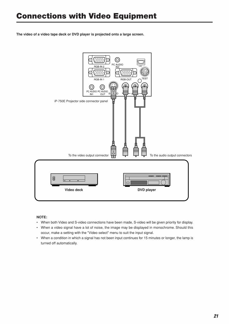
TEST
PC AUDIOIN2
PC AUDIOIN1
PC AUDIOOUT S-VIDEO VIDEO
RGB-OUT
RGB-IN 2
RGB-IN 1
V L R
USB
Connections with Video Equipment
The video of a video tape deck or DVD player is projected onto a large screen.
NOTE:
• When both Video and S-video connections have been made, S-video will be given priority for display.
• When a video signal have a lot of noise, the image may be displayed in monochrome. Should this
occur, make a setting with the "Video select" menu to suit the input signal.
• When a condition in which a signal has not been input continues for 15 minutes or longer, the lamp is
turned off automatically.
iP-750E Projector side connector panel
To the video output connector To the audio output connectors
Video deck DVD player
22
Connection of the Power Cable and On/Off Switching
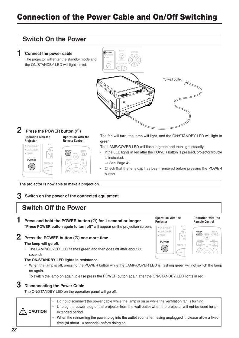
Switch On the Power
1 Connect the power cableThe projector will enter the standby mode and
the ON/STANDBY LED will light in red.
2
The projector is now able to make a projection.
3 Switch on the power of the connected equipment
To wall outlet.
Press the POWER button ( )Operation with theProjector
Operation with theRemote Control
The fan will turn, the lamp will light, and the ON/STANDBY LED will light in
green.
The LAMP/COVER LED will flash in green and then light steadily.
• If the LED lights in red after the POWER button is pressed, projector trouble
is indicated.
→ See Page 41
• Check that the lens cap has been removed before pressing the POWER
button.
Switch Off the PowerOperation with theProjector
Operation with theRemote Control1 Press and hold the POWER button ( ) for 1 second or longer
"Press POWER button again to turn off" will appear on the projection screen.
2 Press the POWER button ( ) one more time.The lamp will go off.
• The LAMP/COVER LED flashes green and then goes off after about 60
seconds.
The ON/STANDBY LED lights in resistance.
• When the lamp is off, pressing the POWER button while the LAMP/COVER LED is flashing green will not switch the lamp
on again.
To switch the lamp on again, please press the POWER button again after the ON/STANDBY LED lights in red.
3 Disconnecting the Power CableThe ON/STANDBY LED on the operation panel will go off.
• Do not disconnect the power cable while the lamp is on or while the ventilation fan is turning.
• Unplug the power plug of the projector from the wall outlet when the projector will not be used for an
extended period.
• When the reinserting the power plug into the outlet soon after having unplugged it, please allow a fixed
time (of about 10 seconds) before doing so.
CAUTION
23
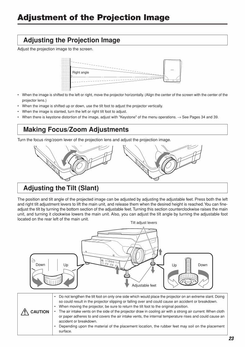
Adjustment of the Projection Image
Adjusting the Projection Image
Adjusting the Tilt (Slant)
The position and tilt angle of the projected image can be adjusted by adjusting the adjustable feet. Press both the leftand right tilt adjustment levers to lift the main unit, and release them when the desired height is reached. You can fine-adjust the tilt by turning the bottom section of the adjustable feet. Turning this section counterclockwise raises the mainunit, and turning it clockwise lowers the main unit. Also, you can adjust the tilt angle by turning the adjustable footlocated on the rear left of the main unit.
Adjust the projection image to the screen.
• When the image is shifted to the left or right, move the projector horizontally. (Align the center of the screen with the center of the
projector lens.)
• When the image is shifted up or down, use the tilt foot to adjust the projector vertically.
• When the image is slanted, turn the left or right tilt foot to adjust.
• When there is keystone distortion of the image, adjust with "Keystone" of the menu operations. → See Pages 34 and 39.
Right angle
Making Focus/Zoom AdjustmentsTurn the focus ring/zoom lever of the projection lens and adjust the projection image.
Up DownUpDown
Tilt adjust levers
Adjustable feet
• Do not lengthen the tilt foot on only one side which would place the projector on an extreme slant. Doingso could result in the projector slipping or falling over and could cause an accident or breakdown.
• When moving the projector, be sure to return the tilt foot to the original position.• The air intake vents on the side of the projector draw in cooling air with a strong air current. When cloth
or paper adheres to and covers the air intake vents, the internal temperature rises and could cause anaccident or breakdown.
• Depending upon the material of the placement location, the rubber feet may soil on the placementsurface.
CAUTION
24
Select the Input
Operation with the Projector
Select the input using the INPUT SELECT buttons.
Each press switches the input one step in the sequence
of OHP → PC1 → PC2 → VIDEO.
Operation with the Remote Control
Select the input using the INPUT SELECT buttons.
When the power of the projector is switched on, the input selection (OHP / PC1 / PC2 / VIDEO) icon is displayed.
1 2
Regular Operation
This section describes the use of direct operation using the projector and remote control buttons.
Please see the items on Page 33 "Menu Operation Method" and Page 36 "Menu Description" for information about
operation using the menu.
OHP
PC2 VIDEOPC1
NOTE:
• The input mode at starting time will be the same as it was the last time the projector was switched off.
• When the icon is displayed, either the left or right key permits input switching.
Operation with the Projector
Press the PORTRAIT button.
Operation with the Remote Control
Press the PORTRAIT button.
A B C
Changing the Orientation of the Projection Image Effective Only with OHP Input
This operation switches the (vertical/horizontal) orientation of the currently projected image.
The display of the switched screen is adjusted to match the width.
25
ABC
To view the portion that has been cut off
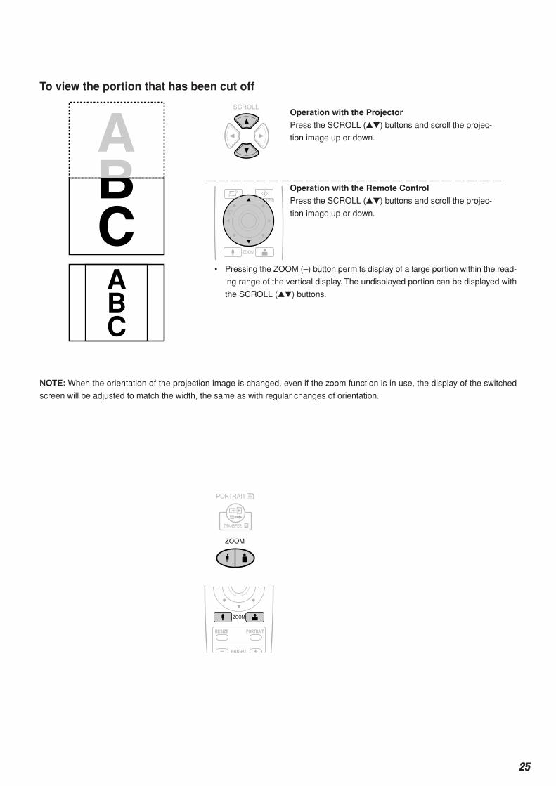
Operation with the Projector
Press the SCROLL () buttons and scroll the projec-
tion image up or down.
Operation with the Remote Control
Press the SCROLL () buttons and scroll the projec-
tion image up or down.
NOTE: When the orientation of the projection image is changed, even if the zoom function is in use, the display of the switched
screen will be adjusted to match the width, the same as with regular changes of orientation.
• Pressing the ZOOM (–) button permits display of a large portion within the read-
ing range of the vertical display. The undisplayed portion can be displayed with
the SCROLL () buttons.
Regular Operation
Enlarging and Reducing the Projection Image
This operation enlarges or reduces the size of projected image.
During OHP input, adjustment from the same size to 6.25 times (length ratio 2.5 times) is permitted, while during PC
or VIDEO input, adjustment from the same size to 16 times (length ratio 4 times) is permitted.
Operation with the Projector
Press the ZOOM button.
: Enlarge the size of the projected image
: Reduce the size of the projected image
Operation with the Remote Control
(+): Enlarge the size of the projected image
(–): Reduce the size of the projected image
26
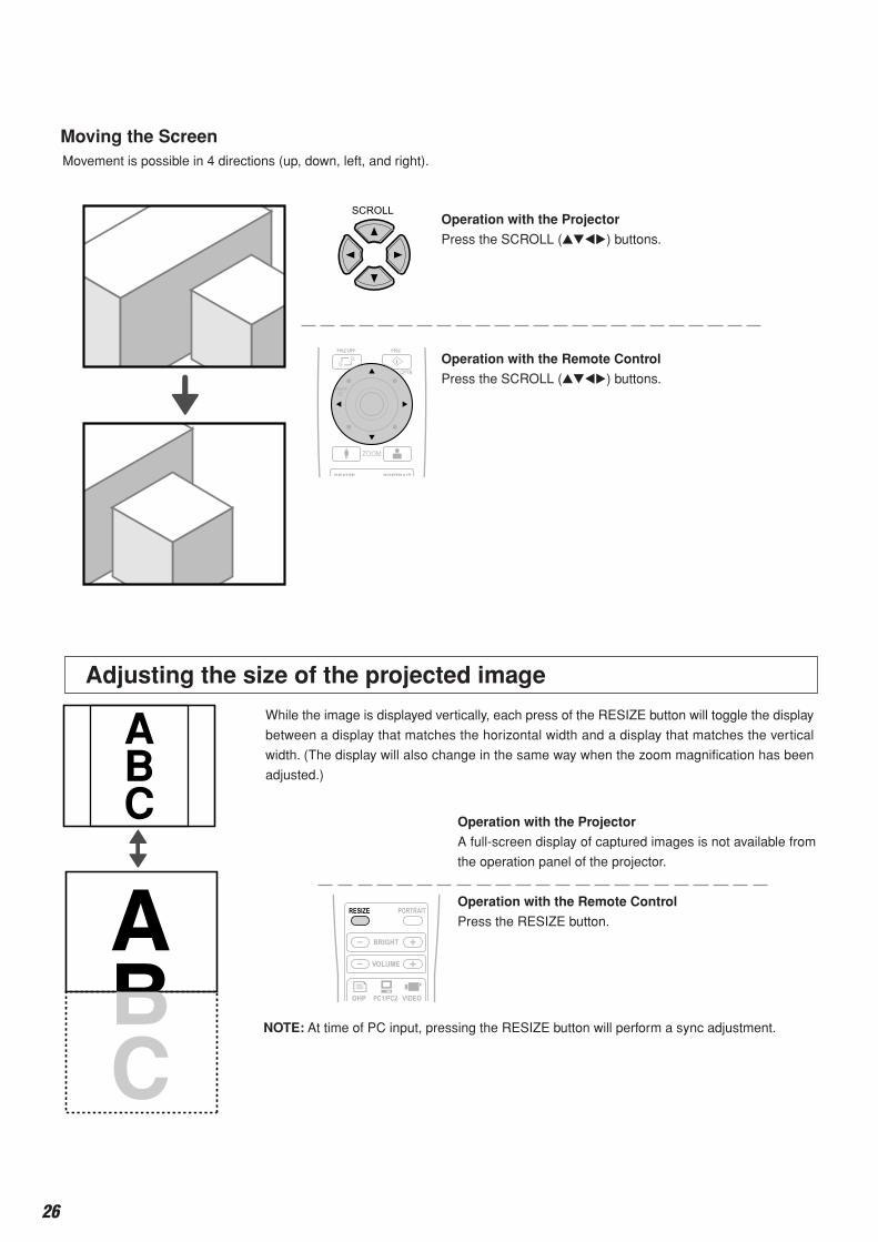
Adjusting the size of the projected image
ABC Operation with the Projector
A full-screen display of captured images is not available from
the operation panel of the projector.
Operation with the Remote Control
Press the RESIZE button.
While the image is displayed vertically, each press of the RESIZE button will toggle the display
between a display that matches the horizontal width and a display that matches the vertical
width. (The display will also change in the same way when the zoom magnification has been
adjusted.)
NOTE: At time of PC input, pressing the RESIZE button will perform a sync adjustment.
Moving the Screen
Operation with the Projector
Press the SCROLL () buttons.
Operation with the Remote Control
Press the SCROLL () buttons.
Movement is possible in 4 directions (up, down, left, and right).
Regular Operation
27
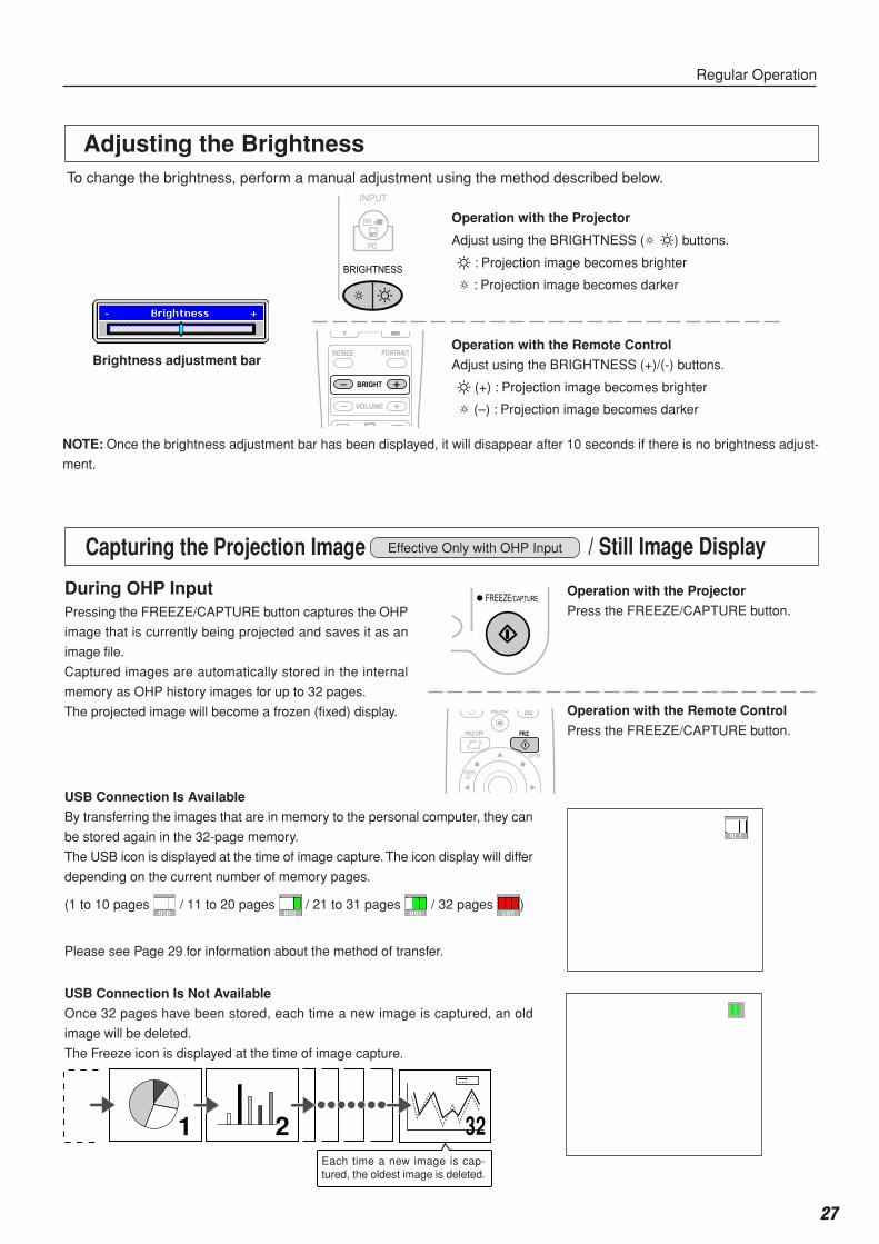
Adjusting the Brightness
NOTE: Once the brightness adjustment bar has been displayed, it will disappear after 10 seconds if there is no brightness adjust-
ment.
Brightness adjustment bar
Operation with the Projector
Adjust using the BRIGHTNESS ( ) buttons.
: Projection image becomes brighter
: Projection image becomes darker
Operation with the Remote Control
Adjust using the BRIGHTNESS (+)/(-) buttons.
(+) : Projection image becomes brighter
(–) : Projection image becomes darker
To change the brightness, perform a manual adjustment using the method described below.
Regular Operation
1 2 3232
1 2 3 4
5 6 7 8
9 10 11 12
13 14 15 16
1 2 3 4
5 6 7 8
9 10 11 12
13 14 15 16
During OHP InputPressing the FREEZE/CAPTURE button captures the OHP
image that is currently being projected and saves it as an
image file.
Captured images are automatically stored in the internal
memory as OHP history images for up to 32 pages.
The projected image will become a frozen (fixed) display.
USB Connection Is Not Available
Once 32 pages have been stored, each time a new image is captured, an old
image will be deleted.
The Freeze icon is displayed at the time of image capture.
USB Connection Is Available
By transferring the images that are in memory to the personal computer, they can
be stored again in the 32-page memory.
The USB icon is displayed at the time of image capture. The icon display will differ
depending on the current number of memory pages.
(1 to 10 pages / 11 to 20 pages / 21 to 31 pages / 32 pages )
Please see Page 29 for information about the method of transfer.
Operation with the Projector
Press the FREEZE/CAPTURE button.
Operation with the Remote Control
Press the FREEZE/CAPTURE button.
Capturing the Projection Image Effective Only with OHP Input
Each time a new image is cap-tured, the oldest image is deleted.
/ Still Image Display
28
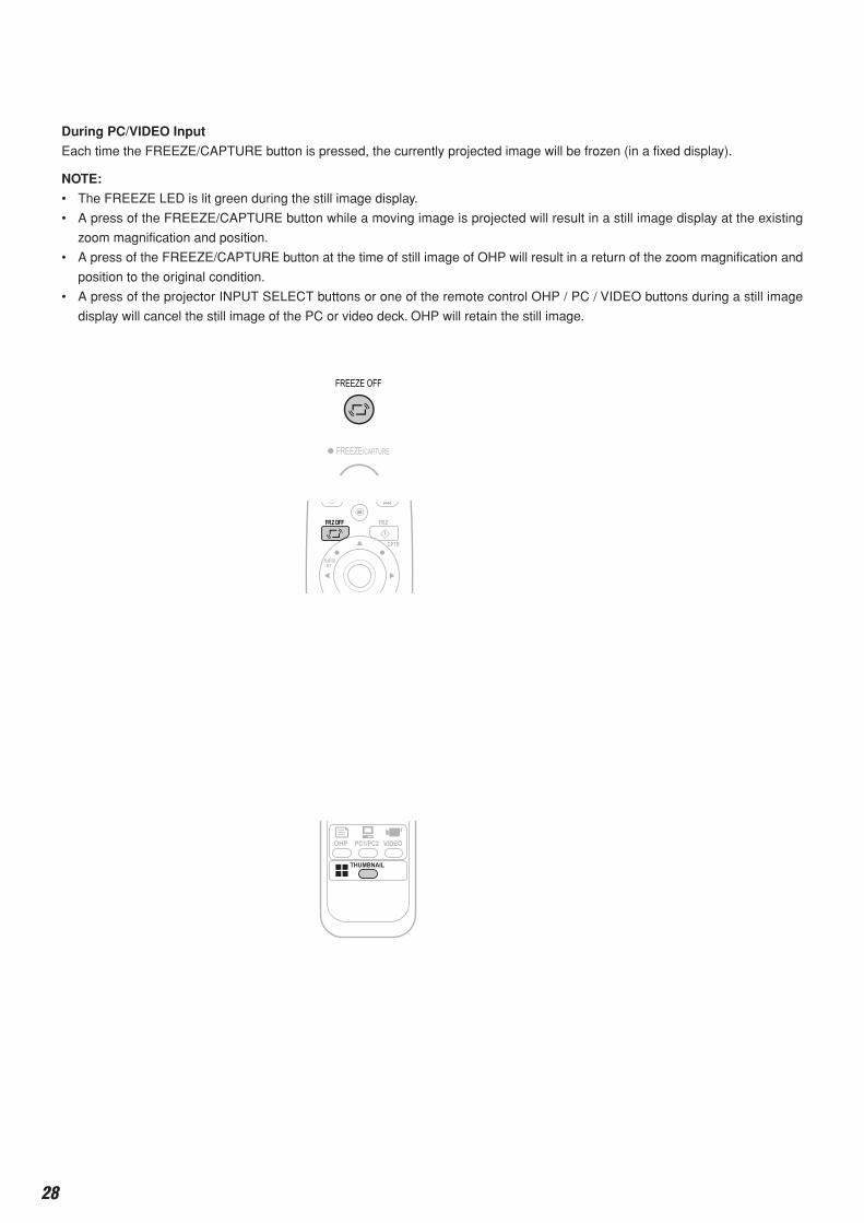
During PC/VIDEO Input
Each time the FREEZE/CAPTURE button is pressed, the currently projected image will be frozen (in a fixed display).
NOTE:
• The FREEZE LED is lit green during the still image display.
• A press of the FREEZE/CAPTURE button while a moving image is projected will result in a still image display at the existing
zoom magnification and position.
• A press of the FREEZE/CAPTURE button at the time of still image of OHP will result in a return of the zoom magnification and
position to the original condition.
• A press of the projector INPUT SELECT buttons or one of the remote control OHP / PC / VIDEO buttons during a still image
display will cancel the still image of the PC or video deck. OHP will retain the still image.
Regular Operation
Cancelling the Still Image Display
Operation with the Projector
Press the FREEZE OFF button.
Operation with the Remote Control
Press the FREEZE OFF button.
NOTE: The FREEZE LED will go off when the still image display is cancelled.
Viewing captured imagesOperation with the Projector
A list display of captured images is not available from
the operation panel of the projector.
Operation with the Remote Control
Press the THUMBNAIL button.
32
1 2 3 4
5 6 7 8
9 10 11 12
13 14 15 16
1 2 3 4
5 6 7 8
9 10 11 12
13 14 15 16
1 2 3 4
5 6 7 8
9 10 11 12
13 14 15 16
Viewing OHP History Images
29
Regular Operation
Full-screen Display of Thumbnail ImagesOperation with the Projector
A full-screen display of captured images is not available
from the operation panel of the projector.
Operation with the Remote Control
Select the images that you would like to display full screen
using the SCROLL () buttons and press the
POINTER/SET button.
32
1 2 3 4
5 6 7 8
9 10 11 12
13 14 15 16
1 2 3 4
5 6 7 8
9 10 11 12
13 14 15 16
1 2 3 4
5 6 7 8
9 10 11 12
13 14 15 16
NOTE: The FREEZE LED is lit orange during the thumbnail display.
Transferring Captured ImagesWhen connection is made with a USB cable,
history images can be transferred to the per-
sonal computer. Please switch the input to
"PC" and press the data TRANSFER button.
Operation with the Projector
Press the TRANSFER button.
NOTE: Please see the attached "iP Viewer Software Quick Reference" or the iP Viewer "Instruction Manual" for information
about the iP Viewer operation method.
Adjusting the VolumeOperation with the Projector
Volume adjustment cannot be made at the operation
panel of the projector.
Operation with the Remote Control
Adjust using the VOLUME (+/-) buttons.
Effective only During PC and VIDEO Input
NOTE: Once the volume adjustment bar has been displayed, it will disappear when 10 seconds have passed without a volume
adjustment operation being made.
Volume adjustment bar
30
Operation with the Projector
The ability to turn on and turn off the pointer is not avail-
able from the operation panel of the projector.
Operation with the Remote Control
Press the POINTER/SET button.
One more press of the POINTER/SET button while the
pointer is displayed will turn off the pointer display.
Moving the Pointer
Operation with the Projector
Press the SCROLL () buttons.
Operation with the Remote Control
Press the SCROLL () buttons.
See Page 36 for information about the form, color, and size of the pointer.
Regular Operation
Displaying the Pointer
This operation displays the pointer in the currently projected image.
NOTE:
• When the brightness is adjusted while the pointer is displayed, the pointer will disappear temporarily; however, it will reappear
soon.
Deleting the Projection Image and Audio
This operation deletes the currently projected image and audio without switching off the lamp.
Operation with the Projector
The ability to delete the projection image is not available from the
operation panel of the projector.
Operation with the Remote Control
Press the MUTE button.
NOTE: When a fixed period of time elapses (about 30 minutes) with the video/audio muted, a message will be displayed to check
whether to shut down the projector. Selection of "Yes" will set the projector to the standby mode, while a selection of "No" will again
delete the video/audio.
When there has been an absence of an operation for 15 seconds during the display of the above confirmation message, the
projector automatically enters the standby mode.
31
Method of OHP Operation
Attaching the Document Cover
The document cover can be removed to suit the circumstances.
NOTE: When removing the document cover, lift the cover by
both hands and remove it.
The maximum reading size of documents and printed material is 216 mm high
by 288 mm wide.
Consequently, when A4 paper (210 mm high and 297.5 mm wide) is placed on
the projector, reading will be as illustrated in the diagram below (which depicts
the area that can be projected as the portion with diagonal lines).
Preparation of the Projection Document
The document (printed material) that is to be projected is placed on the projector as illustrated in the diagram below
and the document cover is closed.
NOTE:
• The document can be projected even when the document cover has not been closed; however, in this instance, unnec-
essary items may be projected which will make the image difficult to view.
• When paper having luster such as magazine covers are placed on the projector, the internal fluorescent lamp light will be
picked up and the edges of the projected document may be messy.
Reading Size of Projection Documents
The portion that falls outside of the reading range will not be projected;
therefore, shift the paper as required.
Other functions that are used in the OHP operation can be seen on the following pages: Switching the input to OHP → See Page 24
Changing the projection image to a still image display → See Page 27
Capturing a projection image → See Page 27
Viewing captured images → See Page 28
Horizontal document Top side
Vertical document
Top side
A4 Paper
297 mm (Paper size)
288 mm (Reading size)
216
mm
(R
eadi
ng s
ize)
210
mm
(P
aper
siz
e)
32
Menu Configuration
Pointer • Screen Image adjustment Settings
OHP/ PC / VIDEO Common During OHP Input OHP / PC / VIDEO Common
During PC Input
During VIDEO Input
The adjustment/setting items and content will differ depending on the input selection and the permitted information will
be displayed on the menu for that input mode.
During OHP History List Display
During OHP History Single-page Display
33
Menu Operation Method
Names and Functions of the Buttons Used in Menu Operation
SCROLL Buttons
Used in the selection of menu names
and item names, and to set and ad-
just item contents.
Names and Functions of the Menu Parts
Sub menu icon
When an item containing this icon is selected, there
is a change to the sub menu.
Returns the set or adjusted item to
the standard value (shipping default
condition of our factory).
Returns to the menu that is one layer higher.
MENU Button
Used to display a menu and
to close a menu.
POINTER/SET Button
Used to finalize a setting after
making the setting or adjustment.
Menu tab
Switches to the various
menus when selected.
Cursor (Light blue)
Selects the item that you
would like to set or ad-
just.
Adjustment bar
Indicates the adjustment
condition according to the
increase or decrease of
the bar point.
34
Menu Operation Method
Method of Menu OperationThis section describes the actual operation method. Adjustment of [Keystone] using the remote control is provided as
an example.
1 Press the MENU button and display the menu
2 Select [Settings] with the SCROLL buttons
Each press of the SCROLL button switches the menu one step in the sequence of [Pointer • Screen] → [Image
adjustment] → [Settings], and each press of the SCROLL button causes a return in the opposite direction.
3 Select [Keystone] with the SCROLL button
Move the cursor and select [Keystone].
35
Menu Operation Method
4 Press the POINTER/SET Button
Switches the menu to the sub menu (i.e., the Keystone
adjustment menu).
5 Make the adjustment with the SCROLL buttons while checking the projection image
Scroll button: Each press increases the value of the verti-
cal orientation. (The top part of the projec-
tion screen will become narrower.)
Scroll button: Each press decreases the value of the ver-
tical orientation. (The bottom part of the pro-
jection screen will become narrower.)
Scroll button: Each press decreases the value of the hori-
zontal orientation. (The left side of the pro-
jection screen will become narrower.)
Scroll button: Each press increases the value of the hori-
zontal orientation. (The right side of the pro-
jection screen will become narrower.)
6 Press the MENU button and close the menu
This completes the [Keystone] adjustment.
36
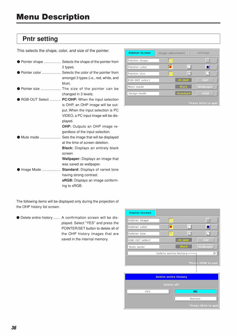
Pntr setting
This selects the shape, color, and size of the pointer.
Pointer shape ................. Selects the shape of the pointer from
2 types.
Pointer color ................... Selects the color of the pointer from
amongst 3 types (i.e., red, white, and
blue).
Pointer size .................... The size of the pointer can be
changed in 3 levels.
RGB-OUT Select ........... PC/OHP: When the input selection
is OHP, an OHP image will be out-
put. When the input selection is PC
VIDEO, a PC input image will be dis-
played.
OHP: Outputs an OHP image re-
gardless of the input selection.
Mute mode ..................... Sets the image that will be displayed
at the time of screen deletion.
Black: Displays an entirely black
screen
Wallpaper: Displays an image that
was saved as wallpaper.
Image Mode ................... Standard: Displays of varied tone
having strong contrast.
sRGB: Displays an image conform-
ing to sRGB.
The following items will be displayed only during the projection of
the OHP history list screen.
Delete entire history ....... A confirmation screen will be dis-
played. Select "YES" and press the
POINTER/SET button to delete all of
the OHP history images that are
saved in the internal memory.
Menu Description
37
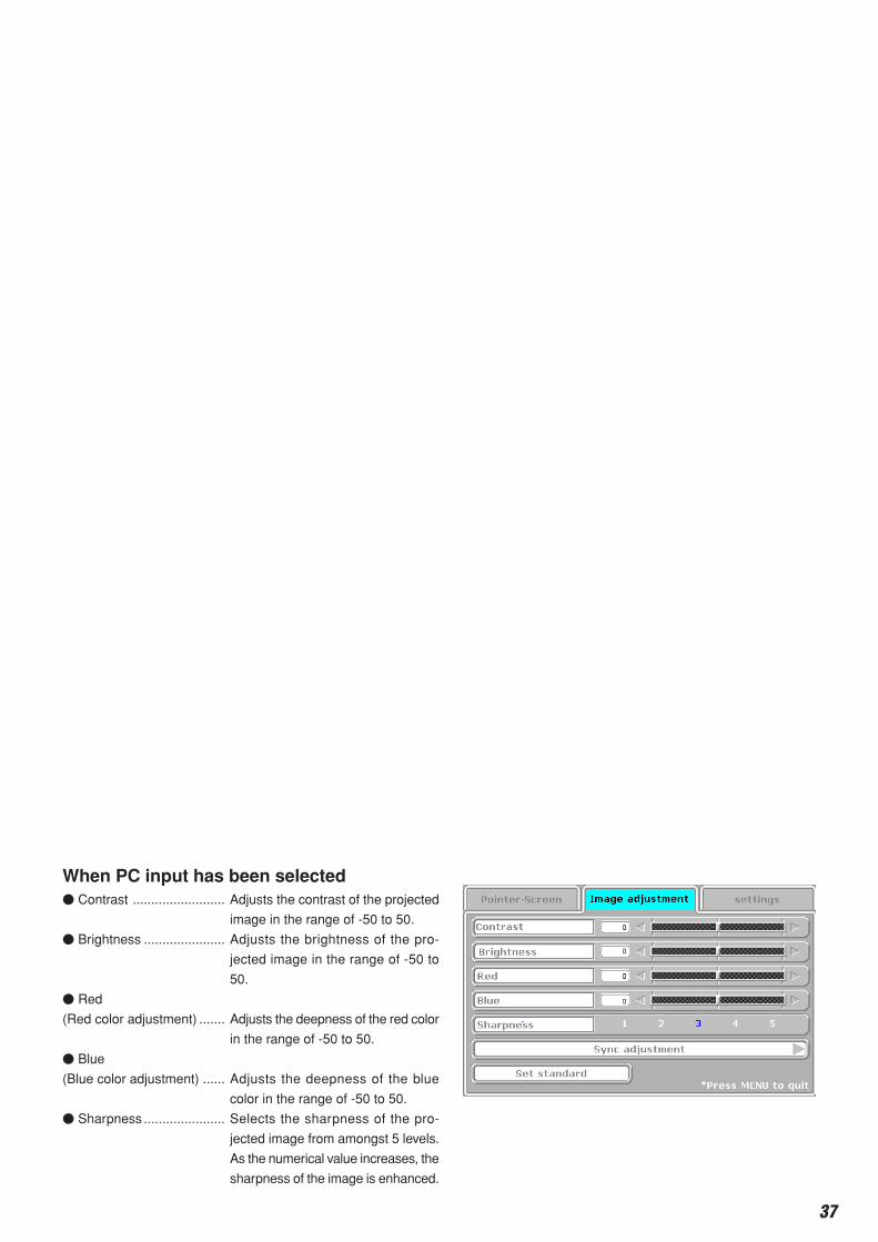
When PC input has been selected Contrast ......................... Adjusts the contrast of the projected
image in the range of -50 to 50.
Brightness ...................... Adjusts the brightness of the pro-
jected image in the range of -50 to
50.
Red
(Red color adjustment) ....... Adjusts the deepness of the red color
in the range of -50 to 50.
Blue
(Blue color adjustment) ...... Adjusts the deepness of the blue
color in the range of -50 to 50.
Sharpness ...................... Selects the sharpness of the pro-
jected image from amongst 5 levels.
As the numerical value increases, the
sharpness of the image is enhanced.
Menu Description
During PC input
Image adjustment
During OHP inputThis performs the settings and adjustments related to the
projected image.
When OHP input has been selected. Red
(Red color adjustment) ....... Adjusts the deepness of the red color
in the range of -50 to 50.
Blue
(Blue color adjustment) ...... Adjusts the deepness of the blue color
in the range of -50 to 50.
The following items will be displayed only during the projection of
the page that was selected from the OHP history list.
Back page in history ...... Switches to the history screen that
was stored before the currently pro-
jected history screen.
Next page in history ....... Switches to the history screen that
was stored immediately after the cur-
rently projected history screen.
Save as wallpaper .......... A confirmation screen will be dis-
played. Select "YES" and press the
Set/Pointer button to save as wallpa-
per the currently displayed history
image.
NOTE:
• Horizontal images that are not being zoomed can be saved as
wallpaper.
• It may not be possible to save images having many colors or
images having a lot of fine patterns.
• When new wallpaper is saved, the previous wallpaper will be
deleted.
38
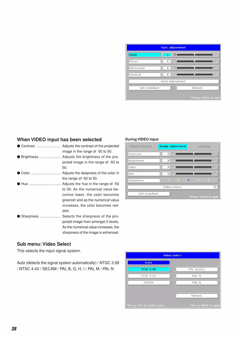
When VIDEO input has been selected Contrast ......................... Adjusts the contrast of the projected
image in the range of -50 to 50.
Brightness ...................... Adjusts the brightness of the pro-
jected image in the range of -50 to
50.
Color .............................. Adjusts the deepness of the color in
the range of -50 to 50.
Hue ................................ Adjusts the hue in the range of -50
to 50. As the numerical value be-
comes lower, the color becomes
greenish and as the numerical value
increases, the color becomes red-
dish.
Sharpness ...................... Selects the sharpness of the pro-
jected image from amongst 5 levels.
As the numerical value increases, the
sharpness of the image is enhanced.
Sub menu: Video SelectThis selects the input signal system.
Auto (detects the signal system automatically) / NTSC 3.58
/ NTSC 4.43 / SECAM / PAL B, G, H, I / PAL M / PAL N
During VIDEO input
Menu Description
Sub menu: Sync adjustment Clock .............................. Adjusts the horizontal size of the pro-
jected image in the range of -50 to
50.
Phase ............................. Adjusts the noise/flickering of the
projected image in the range of -50
to 50.
Horizontal ....................... Adjusts the horizontal position of the
projected image in the range of -50
to 50.
Vertical ........................... Adjusts the vertical position of the
projected image in the range of -50
to 50.
Auto adjustment ............. Performs sync adjustment automati-
cally.
NOTE: Depending on the PC input signal, there might not be a change as far as from -50 to 50.
39
Settings
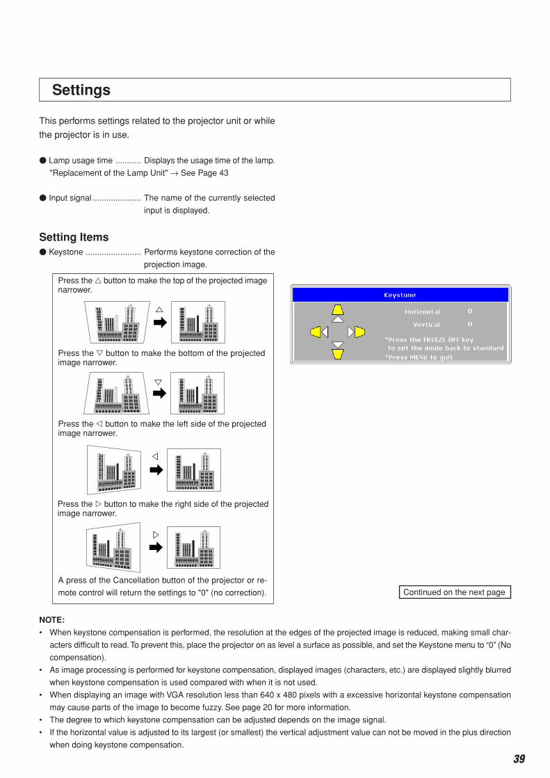
This performs settings related to the projector unit or while
the projector is in use.
Lamp usage time ........... Displays the usage time of the lamp.
"Replacement of the Lamp Unit" → See Page 43
Input signal ..................... The name of the currently selected
input is displayed.
Setting Items Keystone ........................ Performs keystone correction of the
projection image.
Press the button to make the top of the projected imagenarrower.
Press the button to make the bottom of the projectedimage narrower.
NOTE:
• When keystone compensation is performed, the resolution at the edges of the projected image is reduced, making small char-
acters difficult to read. To prevent this, place the projector on as level a surface as possible, and set the Keystone menu to “0” (No
compensation).
• As image processing is performed for keystone compensation, displayed images (characters, etc.) are displayed slightly blurred
when keystone compensation is used compared with when it is not used.
• When displaying an image with VGA resolution less than 640 x 480 pixels with a excessive horizontal keystone compensation
may cause parts of the image to become fuzzy. See page 20 for more information.
• The degree to which keystone compensation can be adjusted depends on the image signal.
• If the horizontal value is adjusted to its largest (or smallest) the vertical adjustment value can not be moved in the plus direction
when doing keystone compensation.
Continued on the next page
Press the button to make the left side of the projectedimage narrower.
Press the button to make the right side of the projectedimage narrower.
A press of the Cancellation button of the projector or re-
mote control will return the settings to "0" (no correction).
Menu Description
40
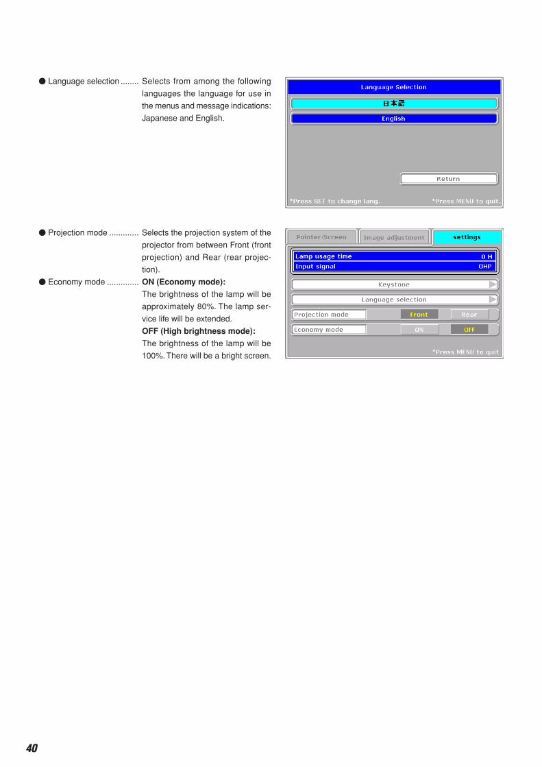
Language selection ........ Selects from among the following
languages the language for use in
the menus and message indications:
Japanese and English.
Projection mode ............. Selects the projection system of the
projector from between Front (front
projection) and Rear (rear projec-
tion).
Economy mode .............. ON (Economy mode):
The brightness of the lamp will be
approximately 80%. The lamp ser-
vice life will be extended.
OFF (High brightness mode):
The brightness of the lamp will be
100%. There will be a bright screen.
Menu Description
41
Maintenance
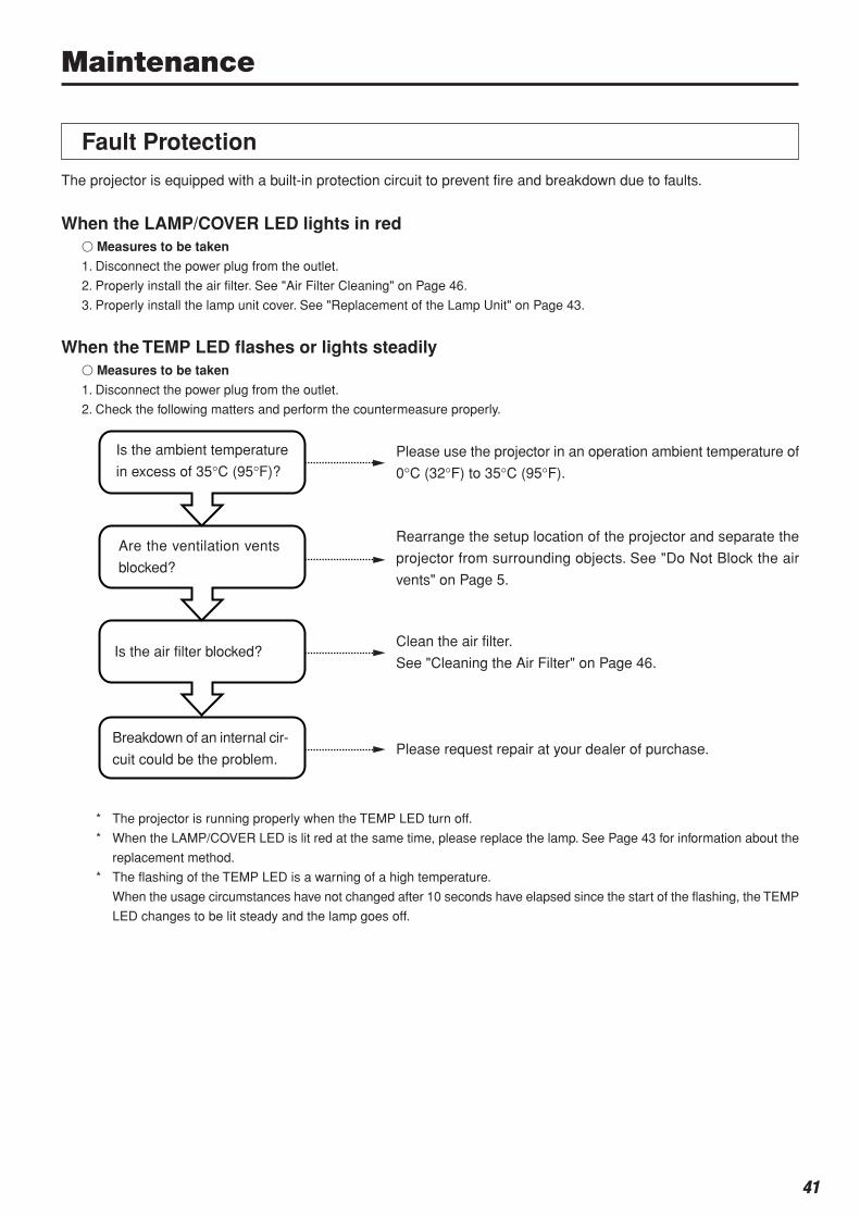
The projector is equipped with a built-in protection circuit to prevent fire and breakdown due to faults.
When the LAMP/COVER LED lights in red Measures to be taken
1. Disconnect the power plug from the outlet.
2. Properly install the air filter. See "Air Filter Cleaning" on Page 46.
3. Properly install the lamp unit cover. See "Replacement of the Lamp Unit" on Page 43.
When the TEMP LED flashes or lights steadily Measures to be taken
1. Disconnect the power plug from the outlet.
2. Check the following matters and perform the countermeasure properly.
Fault Protection
Is the ambient temperature
in excess of 35°C (95°F)?Please use the projector in an operation ambient temperature of
0°C (32°F) to 35°C (95°F).
Are the ventilation vents
blocked?
Rearrange the setup location of the projector and separate the
projector from surrounding objects. See "Do Not Block the air
vents" on Page 5.
Is the air filter blocked?Clean the air filter.
See "Cleaning the Air Filter" on Page 46.
Breakdown of an internal cir-
cuit could be the problem.Please request repair at your dealer of purchase.
* The projector is running properly when the TEMP LED turn off.
* When the LAMP/COVER LED is lit red at the same time, please replace the lamp. See Page 43 for information about the
replacement method.
* The flashing of the TEMP LED is a warning of a high temperature.
When the usage circumstances have not changed after 10 seconds have elapsed since the start of the flashing, the TEMP
LED changes to be lit steady and the lamp goes off.

42
When the power has failed (When all the LED go off with the power ON) Measures to be taken
1. Disconnect the power plug from the outlet.
2. Check the following matters and perform the countermeasure properly.
Maintenance
Is the ambient temperature in
excess of 35°C (95°F)?
Are the ventilation vents
blocked?
Is the air filter blocked?
Breakdown of an internal cir-
cuit could be the problem.
Please use the projector in an operation ambient tempera-
ture of 0°C (32°F) to 35°C (95°F).
Rearrange the setup location of the projector and separate
the projector from surrounding objects. See "Do Not Block
the air vents" on Page 5.
Clean the air filter.See "Cleaning the Air Filter" on Page 46.
Please request repair at your store of purchase.

43
• There is no compatibility with the lamp units of other MP/iP series. Please specify the dedicated lamp
unit (Model: MPLK-D1).
Replacement of the Lamp UnitGuidelines for the replacement of the projection lamp used in this projector are described below. (The time may be shorter
depending on usage conditions.)
When the usage time exceeds the time described below, the likelihood of rupture increases, the projector will be forced to
turn off the projection lamp.
When the lamp usage time has exceeded 1400 hours, please replace the lamp unit (available separately). Also, when the image
becomes dark or the hue worsens, we recommend to replace the lamp; please replace with a new lamp unit.
When messages such as the following appear when the lamp lights.
(This will be displayed when the lamp usage time exceeds 1400 hours.)
When "Lamp usage time" on the menu display screen becomes 1400 hours.
The LAMP/COVER LED flashes red.
The lamp usage time is displayed in the "Settings" menu and can be checked. (See Page 39.)
When the LAMP/COVER LED lights in red without the lamp lighting.
(When the lamp usage time has exceeded 1500 hours.)
Maintenance
• Do not replace the lamp unit immediately after using the projector.
The lamp is high temperature and you could get burned. Disconnect the power plug from the outlet and
wait one hour or longer before replacing the lamp.
• Do not touch the glass portion of the lamp unit with your hands. Doing so could lower the brightness
and shorten the life of the lamp.
• There is a large number of glass parts such as the lamp and mirrors that are used inside the projector.
If a glass part breaks, please exercise due caution in handling so that you are not injured by fragments.
Please request repair from the store of purchase or an AVIO customer support center.
WARNING
CAUTION
44
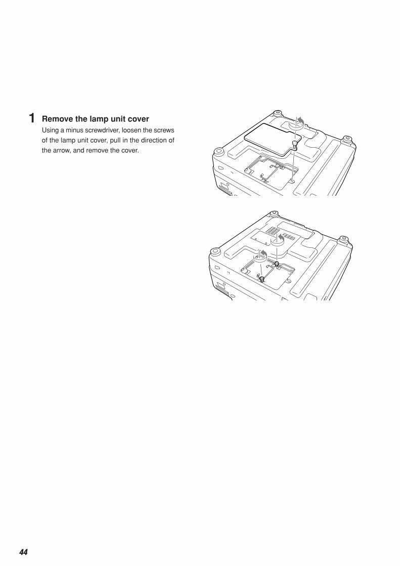
1 Remove the lamp unit coverUsing a minus screwdriver, loosen the screws
of the lamp unit cover, pull in the direction of
the arrow, and remove the cover.
Maintenance
2 Loosen the mounting screws of the lamp unitUsing a minus screwdriver, loosen the 2 screws of
the lamp unit.
3 Pull out the lamp unitHold the handle of the lamp unit and pull it up and out.
4 Install a new lamp unit Take the lamp unit and press it into the projec-
tor.
Tighten the 2 mounting screws of the lamp unit.
Align the 2 tabs located on the lamp unit cover
with the projector and attach from the side of the
tabs. Tighten the mounting screws of the lamp
unit cover.
Lamp Unit Replacement Procedure
To prevent burns, wait one hour or longer after
the lamp has been switched off before perform-
ing the following procedure.

45
Maintenance
5 Reset the lamp usage timePlease perform the operation indicated below in the standby mode (*).
6 Check that the indication of the lamp
usage time has become "0 H" as illus-
trated in the diagram to the right.If the usage time has not been reset, please reset it
by following Step 5 again.Check the lamp usage time by pressing the menu button
of the remote control to display the menu, then use the
scroll button to display the setup setting.
• Do not reset the lamp usage time without replacing the lamp.
The likelihood of the lamp rupturing becomes higher when the lamp has been used in excess of 2000
hours.
CAUTION
NOTE:
• In the interest of safety, the lamp will not light when the lamp unit cover is off.
• The lamp units that are available separately are sold together with an air filter as a set in a lamp kit; therefore, please also
replace the air filter at the same time as lamp unit replacement. (See Page 46.)
• Lamp units can be disposed of using the same disposal method as household fluorescent lamps in accordance with the
regulations of your region.
Operation with the Projector
Press these buttons in order while pressing the but-
ton.
Operation with the Remote Control
Resetting of the lamp usage time cannot be performed with the remote
control.
The LAMP/COVER LED will flash green following this and projection will start.
* The power plug is plugged into a power outlet and only the ON/STANDBY LED is lit red.
If the lamp is used without resetting the usage time, the correct lamp usage time will not be known;
therefore, be sure to reset the usage time after lamp replacement. When the indication exceeds 2000
hours, the projector will be forced to turn off the projection lamp.
CAUTION
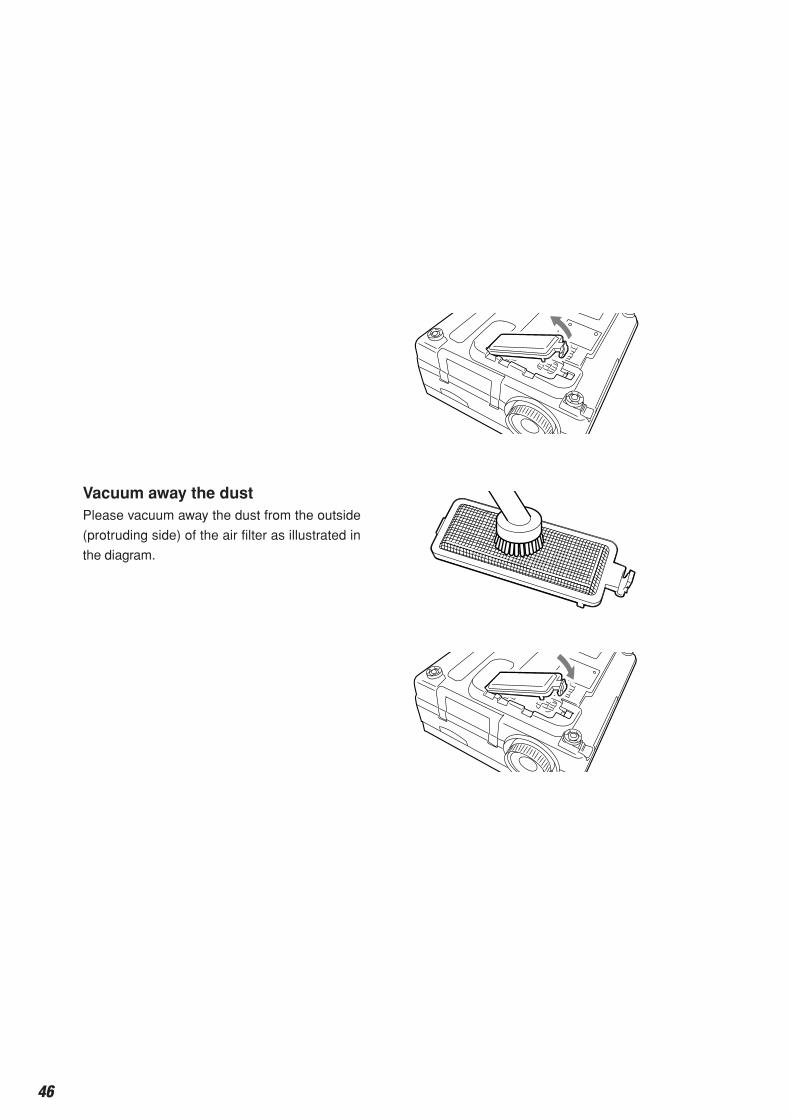
46
Vacuum away the dustPlease vacuum away the dust from the outside
(protruding side) of the air filter as illustrated in
the diagram.
Maintenance
1 Remove the air filter coverPress the 2 tabs of the air filter cover downward
while swinging the cover outward to remove the
air filter cover.
Air Filter Cleaning Procedure
Cleaning the Air Filter
The air filter is an important part that prevents the intrusion of dust onto the optical parts and other parts inside the
projector. When the air filter becomes blocked, the internal temperature will rise and the rotation of the fan will also
increase leading to a reduction of the service life or causing breakdown. In view of this, the air filter should be cleaned
regularly (about once a month, when the projector is used 4 hours per day).
Note that the air filter should be replaced with a new one when it becomes difficult to clean out the dust.
2
3 InstallInstallation is performed by following the steps
for removal in reverse order. Press in the air filter
cover until a click sound is heard.
Air filter care and precautions
• Do not wash with water nor with hot water. Doing so will cause blockage.
• Do not wipe with a cloth or damp rag. Doing so will cause blockage.
• Be careful not to forget to install the air filter. Leaving the projector without a filter installed will allow dust
to enter the inside of the projector and the image quality may worsen.
• When the air filter is damaged, be sure to replace it with a new air filter (available separately as the
MPAF-C1). Use of the projector with a damaged filter will result in dust entering the inside of the
projector and this will cause the image quality to worsen.
CAUTION
NOTE: The lamp will not light unless the air fiter is installed.
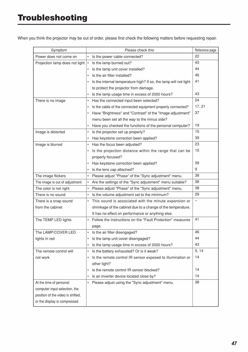
47
Troubleshooting
Power does not come on
Projection lamp does not light
There is no image
Image is distorted
Image is blurred
The image flickers
The image is out of adjustment
The color is not right
There is no sound
There is a snap sound
from the cabinet
The TEMP LED lights
The LAMP/COVER LED
lights in red
The remote control will
not work
At the time of personal
computer input selection, the
position of the video is shifted,
or the display is compressed
When you think the projector may be out of order, please first check the following matters before requesting repair.
Symptom Please check this Reference page
22
43
44
46
41
43
24
17, 21
37
19
15
39
23
15
39
9
38
38
38
29
–
41
46
44
43
5, 14
14
14
14
38
• Is the power cable connected?
• Is the lamp burned out?
• Is the lamp unit cover installed?
• Is the air filter installed?
• Is the internal temperature high? If so, the lamp will not light
to protect the projector from damage.
• Is the lamp usage time in excess of 2000 hours?
• Has the connected input been selected?
• Is the cable of the connected equipment properly connected?
• Have "Brightness" and "Contrast" of the "Image adjustment"
menu been set all the way to the minus side?
• Have you checked the functions of the personal computer?
• Is the projector set up properly?
• Has keystone correction been applied?
• Has the focus been adjusted?
• Is the projection distance within the range that can be
properly focused?
• Has keystone correction been applied?
• Is the lens cap attached?
• Please adjust "Phase" of the "Sync adjustment" menu.
• Are the settings of the "Sync adjustment" menu suitable?
• Please adjust "Phase" of the "Sync adjustment" menu.
• Is the volume adjustment set to the minimum?
• This sound is associated with the minute expansion or
shrinkage of the cabinet due to a change of the temperature.
It has no effect on performance or anything else.
• Follow the instructions on the "Fault Protection" measures
page.
• Is the air filter disengaged?
• Is the lamp unit cover disengaged?
• Is the lamp usage time in excess of 2000 hours?
• Is the battery exhausted? Or is it weak?
• Is the remote control IR sensor exposed to illumination or
other light?
• Is the remote control IR sensor blocked?
• Is an inverter device located close by?
• Please adjust using the "Sync adjustment" menu.

48
Repair Service Procedure• Before asking for repair service, check the Troubleshooting section on page 47 once more. If this check confirms a problem,
contact the dealer where you bought the product.
• When asking for repair service, provide your dealer with the following information:Description of the problem (as many details as possible)Date of purchaseYour NameYour AddressTelephone numberProduct name and model No. (written on the label at the bottom of the projector)
Repair Service
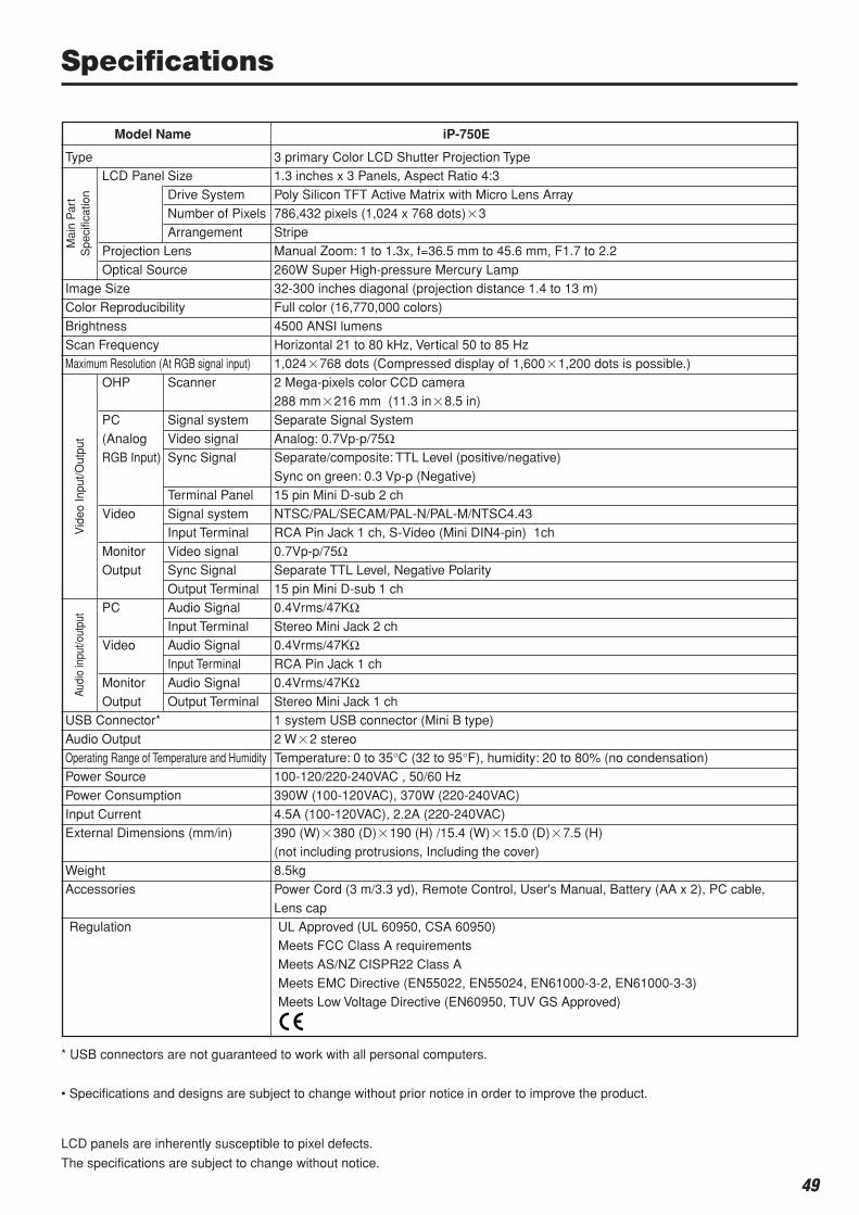
49
Model Name
TypeLCD Panel Size
Drive System
Number of PixelsArrangement
Projection Lens
Optical SourceImage Size
Color Reproducibility
BrightnessScan Frequency
Maximum Resolution (At RGB signal input)
OHP Scanner
PC Signal system
(Analog Video signalRGB Input) Sync Signal
Terminal PanelVideo Signal system
Input Terminal
Monitor Video signalOutput Sync Signal
Output TerminalPC Audio Signal
Input Terminal
Video Audio SignalInput Terminal
Monitor Audio Signal
Output Output TerminalUSB Connector*
Audio Output
Operating Range of Temperature and HumidityPower Source
Power Consumption
Input CurrentExternal Dimensions (mm/in)
WeightAccessories
Regulation
iP-750E
3 primary Color LCD Shutter Projection Type1.3 inches x 3 Panels, Aspect Ratio 4:3
Poly Silicon TFT Active Matrix with Micro Lens Array
786,432 pixels (1,024 x 768 dots)3Stripe
Manual Zoom: 1 to 1.3x, f=36.5 mm to 45.6 mm, F1.7 to 2.2
260W Super High-pressure Mercury Lamp32-300 inches diagonal (projection distance 1.4 to 13 m)
Full color (16,770,000 colors)
4500 ANSI lumensHorizontal 21 to 80 kHz, Vertical 50 to 85 Hz
1,024768 dots (Compressed display of 1,6001,200 dots is possible.)
2 Mega-pixels color CCD camera288 mm216 mm (11.3 in8.5 in)
Separate Signal System
Analog: 0.7Vp-p/75ΩSeparate/composite: TTL Level (positive/negative)
Sync on green: 0.3 Vp-p (Negative)
15 pin Mini D-sub 2 chNTSC/PAL/SECAM/PAL-N/PAL-M/NTSC4.43
RCA Pin Jack 1 ch, S-Video (Mini DIN4-pin) 1ch
0.7Vp-p/75ΩSeparate TTL Level, Negative Polarity
15 pin Mini D-sub 1 ch0.4Vrms/47KΩStereo Mini Jack 2 ch
0.4Vrms/47KΩRCA Pin Jack 1 ch
0.4Vrms/47KΩStereo Mini Jack 1 ch1 system USB connector (Mini B type)
2 W2 stereo
Temperature: 0 to 35°C (32 to 95°F), humidity: 20 to 80% (no condensation)100-120/220-240VAC , 50/60 Hz
390W (100-120VAC), 370W (220-240VAC)
4.5A (100-120VAC), 2.2A (220-240VAC)390 (W)380 (D)190 (H) /15.4 (W)15.0 (D)7.5 (H)
(not including protrusions, Including the cover)
8.5kgPower Cord (3 m/3.3 yd), Remote Control, User's Manual, Battery (AA x 2), PC cable,
Lens cap
UL Approved (UL 60950, CSA 60950)Meets FCC Class A requirements
Meets AS/NZ CISPR22 Class A
Meets EMC Directive (EN55022, EN55024, EN61000-3-2, EN61000-3-3)Meets Low Voltage Directive (EN60950, TUV GS Approved)
Mai
n P
art
Spe
cific
atio
nV
ideo
Inpu
t/Out
put
Audi
o in
put/o
utpu
t
* USB connectors are not guaranteed to work with all personal computers.
• Specifications and designs are subject to change without prior notice in order to improve the product.
LCD panels are inherently susceptible to pixel defects.
The specifications are subject to change without notice.
Specifications