Embed Size (px)
Citation preview

Abstract—This paper presents a time control grinding and
mixing system as an application of fuzzy time control discrete
model. The system is designed by keeping in mind a large
number of its industrial applications. The proposed simulation
design of control system has four inputs: volume, density,
viscosity, and selection of product. There are four controlling
elements: rotatory motor, grinding motor, heating and cooling
units, and valves selection, each with time control constraint.
The system consists of four controlled variables measurement
through its sensing mechanism for feed back control. Time
control fuzzy rule is formulated, applied and tested using
MATLAB simulation for the grinding and mixing system.
Index Terms— Fuzzy time control, grinding and mixing
system, industrial application and time control systems.
I. INTRODUCTION
The fuzzy logic and fuzzy set theory deal with
non-probabilistic uncertainties issues. The fuzzy control
system is based on the theory of fuzzy sets and fuzzy logic.
Previously a large number of fuzzy inference systems and
defuzzification techniques were reported. These
systems/techniques with less computational overhead are
useful to obtain crisp output [3],[4]. The crisp output values
are based on linguistic rules applied in inference engine and
defuzzification techniques [5]. Indeed existing fuzzy models
have addressed the way to reason using membership function
and fuzzy rule but did not take into account the time
dependency of output(s) in control systems [2].
In this paper time control issues of binary control outputs with
a specific required time are applied. The output state and its
time are based on the linguistic rules, applied on this new
system. The output logic levels instead of crisp values can be
used as the control outputs to activate the plant components
(or valves) ON or OFF for a specific time determined by the
linguistic values of inputs and fuzzy inference system. This
research work applies the fuzzy time control concept on
grinding and mixing system. This proposed design work can
be utilised in a wide range of industrial applications: paints,
Manuscript received November 26 , 2008.
F. A. M.Saleem Khan is with the GC University Lahore Pakistan, working
as an assistant professor in the field of Electronics. Currently availing a
research fellowship at The School of Electronics & Engineering in
Edinburgh University UK (e-mail [email protected], [email protected])
S. B. Khaled Benkrid is with the School of Electronics & Engineering in
Edinburgh University UK, working as a lecturer and research supervisor at
The University.(e-mail [email protected])
food processing, dairy products, ice cream plants,
bio-medicines, detergents and soaps manufacturing. This
control system is applicable in the manufacturing plants of a
large number of daily used items, composed of various
grinded materials, mixed with liquids and processed for
certain time limit under temperature controlled environment.
The proposed system can be adapted for grinding the various
items and mixing with liquids or gasses need to be processed
in temperature control environment with a limit of specific
time.
II. FUZZY TIME CONTROL DISCRETE EVENT SYSTEM
Fuzzy logic time control system along with a discrete event
system is called a fuzzy time control discrete event system.
.
Fig. 1 Two modules of FDECS
Fuzzy logic time control system needs a fuzzifier, inference
kernel connected with knowledge base including data base,
rule base and output membership functions (for output
variables and output time control). In this system as shown in
Fig. 2, two defuzzifiers: one for output variable, and another
for output time control are used [2].Time control pulsar
converts the time crisp value into a pulse of specific time
duration. In analog to digital converter (ADC) pulse strobe
unit, ADC converts the output crisp value into binary code
and pulse strobe part allows the code to pass for the specific
pulse duration. This binary code is used to activate the
discrete event control system to generate specific event for a
certain time. In this way combination of fuzzy logic time
control system and discrete event system will form a fuzzy
discrete event control system [3], [6].
Fig. 2 Fuzzy discrete event controller system (FDECS) block diagram.
This new technique reduces complexity of the existing fuzzy
DEV system. We can combine fuzzy logic systems with
A Proposed Grinding and Mixing System using
Fuzzy Time Control Discrete Event Model for
Industrial Applications
M. Saleem Khan, Khaled Benkrid
Proceedings of the International MultiConference of Engineers and Computer Scientists 2009 Vol IIIMECS 2009, March 18 - 20, 2009, Hong Kong
ISBN: 978-988-17012-7-5 IMECS 2009
discrete event (DEV) systems as well as with discrete time
system (DTS) using a minor hardware burden. The system can
also work as a fuzzy discrete time control system with minor
changes in system control, time control and event selection
techniques. The new approach will also reduce complexity of
traditional modeling and its implementation. These
advantages of the new system will make the system popular in
control system industry [2].
III. BASIC STRUCTURE OF PROPOSED GRINDING AND MIXING
SYSTEM
Fig. 3 Fuzzy logic time control DEV grinding and mixing system.
There are four set points: volume, density, viscosity and select
items. These set points provide the crisp values of four fuzzy
input variables to the fuzzifier. The fuzzifier compares the
inputs crisp values with certain levels and generates linguistic
values of each input variable for inference kernel connected
with knowledge base. The knowledge base consists of: data
base; which provides the necessary definitions used to define
linguistic control rules and fuzzy data manipulation in a fuzzy
logic controller, rule base; which characterizes the control
goals and control policy of the domain experts with the help of
a set of linguistic control rules and, output membership
functions; for output variables strength and output time
control. The inference kernel simulates human decision with
fuzzy concepts, implication and rules of inference in fuzzy
logic [1]. The defuzzifier converts the inferred fuzzy control
action into crisp values. This system has eight defuzzifiers:
four defuzzifiers; for the output variables, rotating motor
speed, grinding motor speed, temperature control unit and
valves selection for a particular product, and four
defuzzifiers; for the time constraints of output variables.
IV. DESIGN ALGORITHM
This system is designed for four fuzzy input variables. The
membership functions for the four variables, volume, density,
viscosity and item select are shown in Table I.
TABLE I
MEMBERSHIP FUNCTIONS OF INPUT VARIABLES: VOLUME-
DENSITY-VISCOSITY AND ITEM SELECTION
We have to open a number of valves according to the given
select item scheme shown in Table II, considering maximum
100 valves used at feed lines for materials in flow. The plots
of membership functions for each input fuzzy variable are
shown in Fig.4, Fig5, Fig.6 and Fig.7.
TABLE II
FEED VALVES SELECTION
The crisp value output of valve selection defuzzifier is
converted into digital signal using analog to digital converter
ADC and decoded for the selection of specific valves
opening.
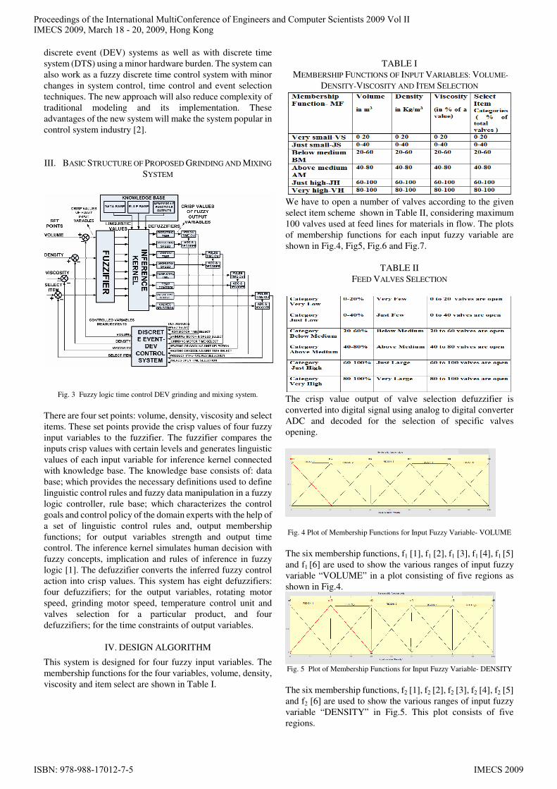
Fig. 4 Plot of Membership Functions for Input Fuzzy Variable- VOLUME
The six membership functions, f1 [1], f1 [2], f1 [3], f1 [4], f1 [5]
and f1 [6] are used to show the various ranges of input fuzzy
variable “VOLUME” in a plot consisting of five regions as
shown in Fig.4.
Fig. 5 Plot of Membership Functions for Input Fuzzy Variable- DENSITY
The six membership functions, f2 [1], f2 [2], f2 [3], f2 [4], f2 [5]
and f2 [6] are used to show the various ranges of input fuzzy
variable “DENSITY” in Fig.5. This plot consists of five
regions.
Proceedings of the International MultiConference of Engineers and Computer Scientists 2009 Vol IIIMECS 2009, March 18 - 20, 2009, Hong Kong
ISBN: 978-988-17012-7-5 IMECS 2009

Fig.6 Plot of Membership Functions for Input Fuzzy Variable- VISCOSITY
f3 [1], f3 [2], f3 [3], f3 [4],) f3 [5] and f3 [6] are the membership
functions used to show the various ranges of input fuzzy
variable “VISCOSITY” in a plot consisting of five regions in
Fig.6.
The numbers of membership functions and the range values
for each variable may be taken different according to the
need. In this system, these are taken same as for
simplification.
Fig.7 Plot of Membership Functions for Input Fuzzy
Variable-ITEM-SELECT.
The six membership functions, f4 [1], f4 [2], f4 [3], f4 [4], f4 [5]
and f4 [6] are used to show the various ranges of input fuzzy
variable “ITEM- SELECT” in Fig.7. The plot in Fig.7
consists of five regions.
There are eight output variables. The plot of membership
function for each variable consists of five functions. The
detail of each membership function is shown in Table III
TABLE III
OUTPUT MEMBERSHIP FUNCTIONS
For simplification, the range values of each output
membership function plot are taken same. Therefore, shape of
the plot for each output variable used in this proposed design
is same and shown in Fig. 8
Fig.8 Plot of Output Membership function
A. Fuzzification
The proposed fuzzy time control design model for Grinding
and Mixing System consists of four fuzzy input variables.
The value of each variable may lie in any one of the five
regions. f1 and f2 are the linguistic values of fuzzy variable
“Volume”, f3 and f4 for “Density”, f5 and f6 for “Viscosity”,
and f7 and f8 for “item-Select”..
The linguistic values are the mapping values of the fuzzy
input variables with the membership functions occupied in the
regions. As we are using four variables, therefore eight
linguistic values are shown in Fig.9
The mapping of input fuzzy variables with the functions in
five regions is listed in Table IV.
TABLE IV
LINGUISTIC VALUES OF FUZZIFIERS OUTPUTS IN ALL REGIONS
Fig.9 Fuzzifier Showing, 4- Inputs- Crisp Values and 8-Outputs- Linguistic
Variables.
As the density and viscosity are directly proportional to each
others, therefore these two variables will lie in one region but
volume and item-select may lie in any of the regions. In this
case 36 rules are required for the complete simulation of the
control system keeping density and viscosity in one region but
if we need any one of the other region for density and
viscosity, the number of rules for complete simulation will be
exceeded to 216 rules and the rule base will maintain the
record of these rules. Again in this case 16 rules will be fired
for the values of one set of input variables.
For the discussion of design algorithm, we used specific
values of input fuzzy variables, “Volume”, “Density”,
“Viscosity” and “Item-Select” in region 1. VOLUME=10,
DENSITY= 15, VISCOSITY=12 and ITEM-SELECT=15.
The corresponding mapping values of f1 [1], f1 [2], f2 [1], f2
[2], f3 [1], f3 [2], f4 [1] and f4 [2] with membership functions
were used to establish the 16 rules.
B. Inference Engine
The inference engine consists of sixteen AND operators,
these are not the logical ANDs but select minimum value
input for the output. This inference engine accepts eight
inputs from fuzzifier and applies the min-max composition to
obtain the output R values.
The min-max inference method uses min-AND operation
between the four inputs.
R1= f1 ^ f3 ^ f5 ^ f7 = f1 [1] ^ f2 [1] ^ f3 [1] ^ f4 [1]
= 0.5^0.75^0.6^0.75=0.5
R2= f1 ^ f4^ f6 ^ f8 = f1 [1] ^ f2 [2] ^ f3 [2] ^ f4 [2]
= 0.5^0.25^0.4^0.25=0.25
R3= f1 ^ f3^ f5^ f8= f1 [1] ^ f2 [1] ^ f3 [1] ^ f4 [2]
= 0.5^0.75^0.6^0.25=0.25
R4= f1 ^ f3^ f6^ f7 = f1 [1] ^ f2 [1] ^ f3 [2] ^ f4 [1]
= 0.5^0.75^0.4^0.75= 0.4
R5= f1 ^ f4^ f5^ f7 = f1 [1] ^ f2 [2] ^ f3 [1] ^ f4 [1]
= 0.5^0.25^0.6^0.75= 0.25
Proceedings of the International MultiConference of Engineers and Computer Scientists 2009 Vol IIIMECS 2009, March 18 - 20, 2009, Hong Kong
ISBN: 978-988-17012-7-5 IMECS 2009

R6= f1 ^ f3^ f6^ f8 =f1 [1] ^ f2 [1] ^ f3 [2] ^ f4 [2]
= 0.5^0.75^0.4^0.25=0.25
R7= f1 ^ f4^ f5^ f8 = f1 [1] ^ f2 [2] ^ f3 [1] ^ f4 [2]
= 0.5^0.25^0.6^0.25=0.25
R8= f1 ^ f4 ^ f6^ f7 = f1 [1] ^ f2 [2] ^ f3 [2] ^ f4 [1]
= 0.5^0.6^0.4^0.75=0.4
R9= f2 ^ f3^ f5^ f7 = f1 [2] ^ f2 [1] ^ f3 [1] ^ f4 [1]
= 0.5^0.75^0.6^0.75= 0.5
R10= f2 ^ f4^ f6^ f8 = f1 [2] ^ f2 [2] ^ f3 [2] ^ f4 [2]
= 0.5^0.25^0.4^0.25=0.25
R11= f2^ f3^ f5^ f8 = f1 [2] ^ f2 [1] ^ f3 [1] ^ f4 [2]
=0.5^0.75^0.6^0.25=0.25
R12= f2 ^ f3^ f6 ^ f7= f1 [2] ^ f2 [1] ^ f3 [2] ^ f4 [1]
=0.5^0.75^0.4^0.75=0.4
R13= f2 ^ f4^ f5^ f7= f1 [2] ^ f2 [2] ^ f3 [1] ^ f4 [1]
=0.5^0.25^0.6^0.75=0.25
R14= f2 ^ f3^ f6^ f8= f1 [2] ^ f2 [1] ^ f3 [2] ^f4[2]
=0.5^0.75^0.4^0.25=0.25
R15= f2 ^ f4^ f5^ f8= f1 [2] ^ f2 [2] ^ f3 [1] ^ f4 [2]
=0.5^0.25^0.6^0.25=0.25
R16= f2 ^ f4 ^ f6^ f7= f1 [2] ^ f2 [2] ^ f3 [2] ^ f4 [1]
=0.5^0.6^0.4^0.75=0.4
The sign ^ between the membership function values is used
for Min-ANDing process. In this process we get the minimum
of the function values being ANDed. This interpretation is
used in Mamdani-min process. The diagram of interference
process in Fig.9 shows this type of process.
C. Rule Selector
The rule selector for this system receives four crisp values of
volume, Density, viscosity and item-select. It provides
singleton values of output functions under algorithm rules
applied on design model. For four variables, sixteen rules are
required to find the corresponding values S1, S2, S3, S4, S5,
S6, S7, S8, S9, S9, S10, S11, S12, S13, S14, S15 and S16
according to division of regions. These rules are listed in
Table V
Fig.10 Block Diagram of Inference Process
TABLE V
ILLUSTRATION OF APPLIED RULES ON GRINDING AND MIXING
CONTROL DESIGN MODEL
D. Defuzzifier
This system consists of eight outputs, four for output variables
required to control the actuators of the system and four
outputs are required for time constraint to the power provided
to the actuators. In this system we use the grinding and
rotating motors, the speed of these actuators can be controlled
under time constraint of design model. Heating/ Cooling unit
and feed valves selection within time limit makes the system
more efficient and more versatile to save the time, energy and
engagement in the delay response of feed back circuit.
The defuzzification process provides the crisp values outputs
after estimating its inputs. In this system 32 inputs are given to
the defuzzifier. Sixteen values of R1, R2,…….., R16 from the
outputs of inference engine and sixteen values S1, S2,
………, S16 from the rule selector.
Each defuzzifier estimates the crisp value output according to
the center of average (C.O.A) method using the mathematical
expression , ∑ Si * Ri ⁄ ∑ Ri ,where i = 1 to 16.
V. ESTIMATION OF CRISP VALUES FOR OUTPUT VARIABLES
The singleton values for all sixteen rules listed in Table V are
given in Table VI
TABLE VI
SINGLETON VALUES FOR ALL OUTPUTS VARIABLE
∑ Ri = R1+R2+R3+………….+R16= 5.1
Using mathematical expression ∑ Si * Ri ⁄ ∑ Ri the crisp
values for output variables was determined and the result was
according to the MATLAB simulation shown in Fig.11.
These results are compared in Table VII and found correct
according to the design model.
Proceedings of the International MultiConference of Engineers and Computer Scientists 2009 Vol IIIMECS 2009, March 18 - 20, 2009, Hong Kong
ISBN: 978-988-17012-7-5 IMECS 2009

Fig. 11 MATLAB- Rule Viewer and Simulation Result for Grinding and
Mixing Fuzzy Time Control System
In Fig.11 values of input variables are taken as same for which
system was discussed, VOLUME=10,
DENSITY= 15, VISCOSITY=12 and ITEM-SELECT=15.
TABLE VII
COMPARISON OF RESULTS
VI. SIMULATION RESULT DISCUSSION
According to design scheme of grinding and mixing fuzzy
time control system volume effects; the rotation time,
grinding time, heating/cooling time and valves opening time.
Viscosity and density are directly proportional to each others
and effect; the rotating speed, grinding speed, heating/cooling
temperature, and item selection effects; the number of valves
to be opened. All of these, dependencies of the output
variables on the input variables, are shown in Fig.12.
Fig. 12(a) shows that the valves open time is directly
proportional to the volume and it does not depend upon the
density.
Fig. 12(b) shows that the number of valves opening does not
depend on the volume and density
Fig. 12© indicates that the heating/cooling time depends on
volume and it does not depend upon density.
Fig. 12(d) shows that heating/cooling temperature depends on
density and it does not depend on volume.
Fig. 12(e) gives the proof of grinding time dependency upon
volume and shows that it does not depend on density.
Fig. 12(f) indicates that the grinding motor speed depends on
density and it does not depend on volume.
Fig. 12(g) shows that the rotating time depends on volume
and it does not depend on density.
Fig. 12(h) shows that the rotation speed depends on density
and it does not depend on volume.
Fig. 12(i) indicates that rotation time depends on volume and
does not depend on viscosity.
Fig. 12(j) shows that the density and viscosity are directly
proportional to each others and effect the rotation speed.
(a) Plot between volume-density-valve open time
(b) Plot between volume-density-valve selection
© Plot between volume-density- heating/cooling time
(d) Plot between volume-density- temperature
(e) Plot between volume-density-grinding time
Proceedings of the International MultiConference of Engineers and Computer Scientists 2009 Vol IIIMECS 2009, March 18 - 20, 2009, Hong Kong
ISBN: 978-988-17012-7-5 IMECS 2009

(f) Plot between volume-density- grinding motor speed
(g) Plot between volume-density-rotating time
(h) Plot between volume-density-rotating motor speed
(i) Plot between volume-viscosity-rotating time
(j) Plot between density-viscosity-rotating time
Fig. 12(a to j) MATLAB simulation plots
VII. CONCLUSION AND FUTURE WORK
The result of design model is the same as the simulation result.
This system can be extended for any time control system to
overcome time control issues and achieve better performance
without the burden of extra load for time control.
In this design model rotating motor speed, grinding motor
speed, heating / cooling and feed valves open time depend on
the amount of volume selected. Rotation time, grinding time
and heating time depend on the values of density and
viscosity. The number of valves selection depends on
item-select input variable. The algorithmic design approach
makes the system efficient and completely under time control.
This design and simulation work will open a new discussion
in the field of simulation and control system design. The fuzzy
time control model needs to be developed using FPGA with
its large number of industrial applications. The work on it is
being carried out and in future it will help to design state of the
art fuzzy logic time control discrete event systems in local and
distributed environment.
REFERENCES
[1] Shabiul Islam, Shakowat,”Development of a Fuzzy Logic Controller
Algorithm for Air-conditioning System”, ICSE 2006, Proc. 2006 IEEE.
[2] M.Saleem Khan,”Fuzzy Time Control Modeling of Discrete Event
Systems”, ICIAR-51, WCECS 2008, pp.683-688, International
Conference on Intelligent Automation and Robotics. U.S.A.
[3] Y.Y. Chen and T.C Tsao, ”A description of the dynamic behavior of
fuzzy systems”, IEEE TransVol.19,July 1989, pp. 745-755
[4] W.Pedryez, J.V. de Oliveia,”Optimization of Fuzzy Models”, IEEE
Trans. Syst., Man, Cybern,Vol. 26, August. 1996, pp. 627-636
[5] B. P. Zeigler, P. Herbert ,”Theory of Modeling and Simulation,
Integrating Discrete Event and Continuous Complex Dynamic
Systems” IEEE Press, 1994
[6] M. Sugeno, Tanaka,”Successive identification of a fuzzy model and its
application to prediction of a complex system”, fuzzy sets syst., Vol.
42, 1991, pp. 315-334.
F.A. Mr. M. Saleem Khan is an
Assistant Professor at GC University
Lahore Pakistan. He is currently
availing a research fellowship at The
School of Electronics & Engineering,
University of Edinburgh, UK and
completed his Ph.D thesis in the field
of control systems: design, simulation
and analysis in local and distributed
environment. He contributed his services on various projects
in the field of Advanced Electronics and Communication. His
research interests include control systems design and
industrial applications. He promoted a large team of
Electronics researchers and organized this field in his country.
Mr. Khan had also been served as a senior scientific officer in
a classified defence research organisation in his country.
S.B. Dr. Khaled Benkrid is a
faculty member of The School of
Electronics & Engineering,
University of Edinburgh, UK.
He is HEA fellow, IEEE senior
member, MACM/SIGDA.
His research interests are: Custom
hardware design, Electronic design
automation, construction of optimized compilers, image and
video processing and high performance parallel computing.
Mr. Benkrid is supervising the research scholars in the fields
of advanced Electronics.
Proceedings of the International MultiConference of Engineers and Computer Scientists 2009 Vol IIIMECS 2009, March 18 - 20, 2009, Hong Kong
ISBN: 978-988-17012-7-5 IMECS 2009