Embed Size (px)
Citation preview

NASA
0 N m P n z c e r/l e z
TECHNICAL NOTE
A REAL-GAS STUDY OF LOW-DENSITY WEDGE-INDUCED LAMINAR SEPARATION ON A HIGHLY COOLED BLUNT FLAT PLATE AT M, = 12
by John B. Anders and C. L. W. Edwards
LungZey Reseurcb Center Lungley Stution, Humpton, Vu.
N A S A TN D-4320 - .-
c.f
NATIONAL AERONAUTICS AND SPACE ADMINISTRATION W A S H I N G T O N , D . C. M A R C H 1968
https://ntrs.nasa.gov/search.jsp?R=19680008430 2018-05-30T17:07:05+00:00Z

TECH LIBRARY KAFB, NY
A REAL-GAS STUDY OF LOW-DENSITY WEDGE-INDUCED
LAMINAR SEPARATION ON A HIGHLY COOLED
B L U N T F L A T P L A T E A T M, = 12
By John B. A n d e r s a n d C. L. W. E d w a r d s
L a n g l e y R e s e a r c h C e n t e r Langley Station, Hampton, Va.
NATIONAL AERONAUTICS AND SPACE ADMINISTRATION
For sole by rhe Clearinghouse for Federal Scientific and Technicol Information Springfield, Virginia 22151 - CFSTI price $3.00
I


A REAL-GAS STUDY OF LOW-DENSITY WEDGE-INDUCED
LAMINAR SEPARATION ON A HIGHLY COOLED
BLUNT FLAT PLATE AT M, = 12
By John B. Anders and C. L. W. Edwards Langley Research Center
SUMMARY
A study has been made of real-gas wedge-induced laminar separation. A series of experimental tests on a blunt flat plate with a trailing-edge flap was made at a free- s t ream Mach number of 12 and a free-s t ream Reynolds number of 104/ft (3.3 X lo4/,). The tests were conducted for stagnation enthalpies ranging from 1465 Btu/lbm (3.41 MJ/kg) to 2030 Btu/lbm (4.73 MJ/kg). A calculation technique is developed to predict the chordwise extent of wedge-induced laminar separation and agrees reasonably well with the present real-gas experimental data. The computed effect of f ree-s t ream Reynolds number and total enthalpy on the extent of separation is demonstrated. Sample calculations are shown for equilibrium and frozen flow for a range of total enthalpies.
INTRODUCTION
The occurrence of laminar-boundary-layer separation on maneuverable reentry vehicles results in large changes in aerodynamic characteristics, heat transfer, and con- trol forces. This problem has been studied by many investigators and much theoretical and experimental information exists on laminar separated flows. (See refs. 1 to 22.) However, all the theoretical investigations, and all the experimental investigations with the exception of Kuehn's work (refs. 23 and 24) have considered the fluid to be a perfect gas. Also, with the exception of Rogers and Berry (ref. 25) and Kuehn (refs. 23 and 24), only relatively high-density flows have been investigated, usually with local Reynolds numbers above lo4. The higher kinetic energies of reentering vehicles are normally associated with the early low-density region of the flight path. Therefore, the regions of low density and high enthalpy are linked together for this application.
The extension of present theories to low-density real-gas conditions invariably seems to violate assumptions made in their development. Similarly, the extrapolation of experimental results to low-density real-gas conditions is, perhaps, unfounded without some experimental investigation in this region. The present study was begun to check

experimentally certain semiempirical perfect-gas relations in the real-gas region and to see whether certain gross predictions of low-density real-gas separation could be made by utilizing simple physical concepts. Such a study would be useful in demon- strating trends as well as pointing the way to future research.
The model chosen for this study was a blunt-nosed wing-flap combination. All experimental testing was done in the Langley l-foot hypersonic arc tunnel at a nominal Mach number of 12 and a nominal free-stream Reynolds number per foot of 1.4 x lo4 (4.59 X lo4 per meter). The Knudsen number based on nose diameter was approximately 0.06.
SYMBOLS
a
constants in equations (6) and (7)
speed of sound
C1,C2,C3 constants in equations (ll), (12), and (13)
plateau pressure coefficient, pp - Po cP, P 40
Cf, 0 local-skin-friction coefficient
d model nose diameter
G = 1.7208 -
HO form factor
h enthalpy
ht, 2 stagnation enthalpy at model nose
k nose drag coefficient
k l constant in equation (19)
L model length to wedge hinge line
2

P
pb
Pt, 2
*PV
9
R
X
length of dividing streamline
length over which pressure rise to plateau takes place
Mach number
defined by equations (14a) and (14b)
s ta t ic pressure
bluntness induced pressure
stagnation pressure on model nose
viscous induced pressure increment
dynamic pressure
specific gas constant
Reynolds number per foot (per 0.3048 meter) based on free-s t ream
conditions, - P mVaJ P.0
free-stream Reynolds number based on plate length, P ,V,L Pa3
free-stream Reynolds number based on longitudinal distance
Reynolds number based on conditions at beginning of interaction, pOvoxo P O
distance variable from reference 9
temperature
velocity ratio along dividing streamline, - V v2
velocity component
longitudinal coordinate (see fig. 2)
3

real-gas compressibility factor
(M2 - 1
ra t io of specific heat
angle of dividing streamline with plate surface (see fig. 10)
displacement thickness
function of y, E 1 - 0.0048 (Y -
wedge deflection angle
coefficient of viscosity
defined by equation (17)
correction factor in equations (4) and (5)
mass density of air
defined by equation (18)
viscous interaction parameter, M m 3
6 Subscripts:
aw adiabatic wall
C computed value
0 condition at beginning of interaction
P condition in plateau region
r condition at reattachment
S condition at separation
4
I "
t
W
00
2
stagnation condition
condition on model wall
f ree-s t ream condition
condition at edge of boundary layer
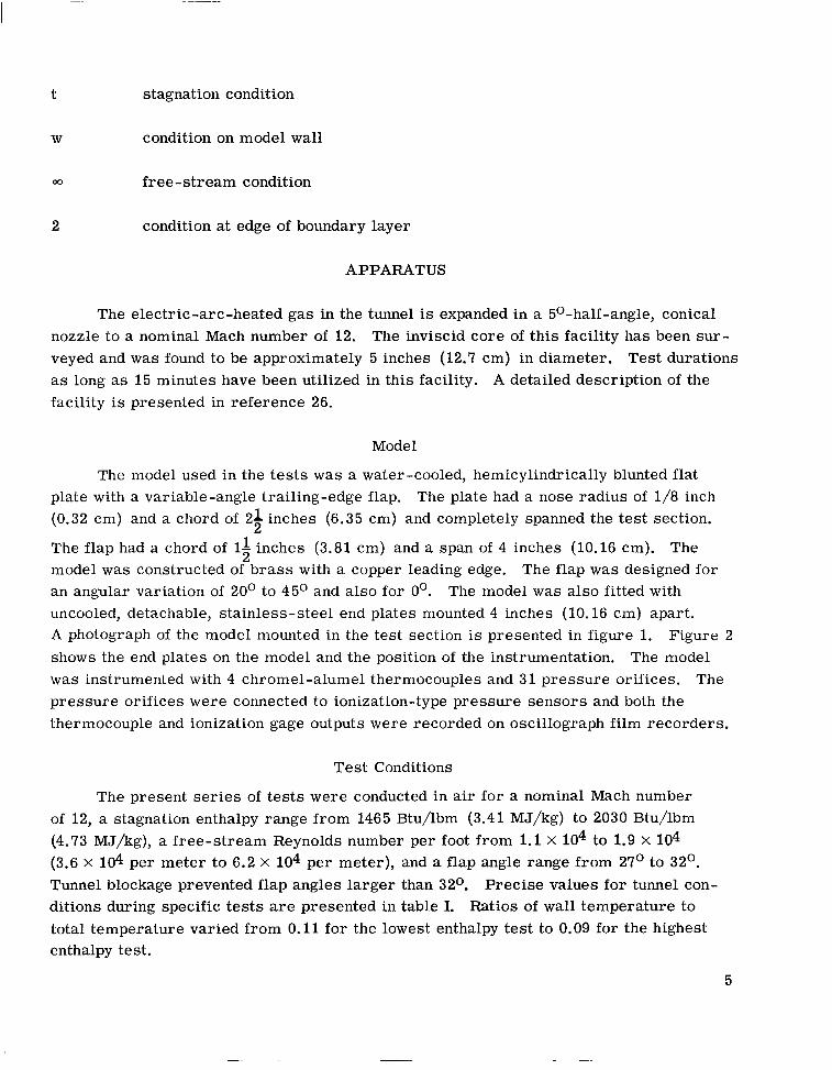
APPARATUS
The electric-arc-heated gas in the tunnel is expanded in a 5O-half-angle, conical nozzle to a nominal Mach number of 12. The inviscid core of this facility has been sur- veyed and w a s found to be approximately 5 inches (12.7 cm) in diameter. Test durations as long as 15 minutes have been utilized in this facility. A detailed description of the facility is presented in reference 26.
Model
The model used in the tests was a water-cooled, hemicylindrically blunted flat plate with a variable-angle trailing-edge flap. The plate had a nose radius of 1/8 inch (0.32 cm) and a chord of 2 1 inches (6.35 cm) and completely spanned the test section.
The flap had a chord of 1 1 inches (3.81 cm) and a span of 4 inches (10.16 cm). The model was constructed of b ra s s with a copper leading edge. The flap was designed for an angular variation of 20° to 45O and also for 0'. The model was also fitted with uncooled, detachable, stainless-steel end plates mounted 4 inches (10.16 cm) apart. A photograph of the model mounted in the test section is presented in figure 1. Figure 2 shows the end plates on the model and the position of the instrumentation. The model was instrumented with 4 chromel-alumel thermocouples and 31 pressure orifices. The pressure orifices were connected to ionization-type pressure sensors and both the thermocouple and ionization gage outputs were recorded on oscillograph film recorders.
2
2
Test Conditions
The present series of tes ts were conducted in air for a nominal Mach number of 12, a stagnation enthalpy range from 1465 Btu/lbm (3.41 MJ/kg) to 2030 Btu/lbm (4.73 MJ/kg), a free-stream Reynolds number per foot from 1.1 X lo4 to 1.9 x 10⁴ (3.6 x 10⁴ per meter to 6.2 X 10⁴ per meter), and a flap angle range from 27O to 32O. Tunnel blockage prevented flap angles larger than 32O. Precise values for tunnel con- ditions during specific tests are presented in table I. Ratios of wall temperature to total temperature varied from 0.11 for the lowest enthalpy test to 0.09 for the highest enthalpy test.
5

-
Test -
1 2 3 4 5 6 7 8 9
10 11 12 -
T ht Btu/lbm
1770 2030 1619 146 5 1850 1720 1950 1640 1998 1690 1830 1785
MJhg
4.12 4.73 3.77 3.41 4.31 4.00 4.54 3.82 4.65 3.93 4.26 4.16 __-
T
Figure 1.- Model installed i n 1-foot test section. End plates removed. L-67-8702
TABLE I.- TUNNEL TEST CONDITIONS
atm
22.36 20.32 22.22 21.82 21.82 21.41 21.17 21.00 21.37 20.39 18.62 23.72
Pt T
N/m2
2.26 X 1 O f 2.06 2.25 2.21 2.21 2.17 2.14 2.13 2.16 2.07 1.89 2.40
PCC at m
5.47 x 10⁻⁵ 5.73 5.09 4.21 5.58 6.34 5.96 5.19 5.62 4.50 5.84 5.67
T N/m2
5.54 5.80 5.16 4.26 5.65 6.42 6.04 5.26 5.70 4.56 5.92 5.74
~
MU3 -
12.4 11.8 12.7 13.1 12.2 12.1 11.9 12.5 12.0 12.7 11.9 12.4 __
per foot
1.5 X 10⁴ 1.1 1.8 1.9 1.4 1.7 1.2 1.7 1.1 1.5 1.3 1.6
- per meter
4.9 X 10⁴ 3.6 5.9 6.2 4.6 5.6 4.9 5.6 3.6 4.9 4.3 5.3
T ~
6, deg __
27.0 28.0 30.5 32.0 31.0 31.0 31.0 30.5 30.5 30.5 30.5 0 -
6

c
-r Pressure orifices - -
Pressure orifices -
Thermocouples
I c I
Stagnation pressure
tap 7
\ 0 0 0 0 1
! I
0 01 0 0
I
Thermo- couples
8.W 12.25
i 2.500 (6.350) * . 1.563 13.969) ---)r .- ~
F igure 2.- Model schematic and instrumentation. (Dimensions are in inches (centimeters).)
7

Accuracy
The maximum error in determining the total enthalpy has been found to be about *8 percent as reported in references 27 and 28. An orifice effect on pressure measure- ment has been investigated and reported in reference 29. This effect can cause a maxi- mum e r r o r in pressure measurements of -6 percent for the lowest pressures measured in these tests. Maximum error due to the orifice effect on higher pressures such as those at separation, plateau, or reattachment is considerably less than -6 percent (usually l e s s than 1 percent). A maximum inaccuracy in instrumentation and reading of data has been found to be *5 percent. The total uncertainty for the lowest measured pressure is then 5 percent and -11 percent. This uncertainty in pressure causes an uncertainty in the calculation of local properties along the plate. Cases were calculated by using the maximum error in pressure and this procedure was found to result in a 2-percent devia- tion in cf,O and a 4-percent deviation in local Mach number. These deviations were considered to be insignificant in the overall results.
RESULTS AND DISCUSSION
Blunt-Plate Pressure Distribution Without Separation
Several tests were made with a Oo flap angle in order to determine the effect of the blunt nose on the pressure distribution over the plate. Figure 3 shows a typical measured pressure distribution with a Oo flap angle. No pressure measurements were made on the flap itself. Two theoretical distributions (refs. 30 and 31) a re a l so shown. The method of Bertram and Blackstock (ref. 30) was found to give the best overall agreement with certain restrictions on y. The method itself is not specifically valid for a variable y
flow; therefore, an attempt was made to represent the flow by some characterist ic y , Kuehn (ref. 32) discusses the use of a characterist ic y for blunt-nosed cylinders. He states that Wick of the NASA Ames Research Center has suggested that the value of y at the stagnation region should be used since the blast analogy describes the flow in terms of a blast wave originating at the nose. In addition to the inviscid blast wave pressure, the viscous induced pressure must be taken into account; and intuitively, this viscous induced pressure might be characterized by a locally constant y . From the analysis of reference 30, the inviscid and viscous pressures are given by the following expressions for Apv small compared with 43
r +/3 + 0.74
pca
8

and
where y in equation (1) is now evaluated at the model stagnation point and y in equa- tion (2) is a local value evaluated at and the stagnation-point entropy., The plate surface pressure is then given by
These equations are used, without further qualification, for calculations presented later in this paper.
Ref. 30 (eqs. (1) and (2) in text with y = 1.4)
eq. (1) evaluated at model nose stagnation point and y in eq. (2) evaluated at local conditions on plate)
Ref. 31, y = 1.4
0 Present experiment, M, = 12.4, R, = 1.6 X 10⁴ per foot, (5.3 X 1d per meter), ht = 1785 Btu/ Ibm (4.16 MJ/kg)
""_ Ref. 30 (eqs. (1) and (2) in text with y in
-. . 1-
8"s""- " ----" - -O- -0-31 0-L 8 - "<
0 L l 0 " 1 L" . I ' I- L-L" 2 3 4 5 6 7 8 9 10
x/d
Figure 3.- Blunt-plate pressure distribution.
Separated Flow Results
Test data were obtained by two methods: oil-flow studies and pressure distribu- tions. The partial-span flap of the present model leads to large three-dimensional effects in the sepa7ation bubble according to reference 33, and end plates were added to the model to minimize this spanwise bleed. A typical result from the addition of end plates is shown
9

in figure 4. The end plates significantly increased the chordwise extent of separation. With the exception of figure 4, all the data presented were taken with the end plates on and the effect of the end plates themselves is discussed in the light of the oil-flow pat- terns and spanwise pressure measurements.
100
10.0
-
4.00 1720 5.3x IO4 1.6X IO4 12.5 30.5
. 0 3.82 1640 5.6~ lo4 1.7~ lo4 12.5 30.5
1.0 t c E "
1 2 3 4 5 6 1 8 9 10 11 12 13 14 15 16 x / d
Figure 4.- End-plate effect.
Oil-flow patterns.- The photographs of the oil-flow patterns were not of sufficient quality to warrant reproduction. However, figure 5 shows the pertinent features indicated by the original prints. Prior to a test, the surface of the plate was cleaned and dotted with drops of thin oil tinted with Prussian blue. The droplets were then observed during tunnel starting, approximately 2 minutes of testing time, and tunnel shutdown. The oil drops were observed to travel slowly back to a point on the plate surface, then to collapse and run together, and thus wet the plate surface. The complete process occurred in 3 to 4 seconds and no change in the pattern could be detected during the remaining test time or during tunnel shutdown. The forward edge of the wetted area w a s assumed to be the separation line and the position of this line is approximately halfway up the pressure rise to plateau pressure. However, on two of the oil-flow tests, the separated region was very
10

small and the pressure distributions did not exhibit a definite plateau. For these tests the oil-flow pattern indicated that separation occurred nearly three-fourths of the way up the pressure rise to the inflection point.
Spanwise pressure gradients. - All the oil-flow tests were made with end plates on, and from fig- u r e 5 the flow appears to be approximately two dimensional near the model center line. The oi l s t reaks on either end of the model near the end plates curve inward slightly and indicate some end-plate effects in this region. Outboard pressure measure- ments were made to check for
al L /Accumulated 3 VI
oil puddle
Puddle width 4II-
Distance
LI"---J
Figure 5.- Sketch of typical oil-flow pattern.
any spanwise pressure gradients in the separated region not indicated by the oil streaks. Unfortunately, one outboard orifice developed a water leak at the onset of the test program and had to be plugged. The remaining outboard orifice indicated center-line pressure within the reading accuracy in 6 of the 11 tests. The other 5 tests indicated an outboard pressure 22 percent to 27 percent lower than the center line. This result might be expected since the separation pressure rise for most of the tests occurred near the out- board orifice. A slight spanwise variation in separation length could cause a fairly large variation in the pressure level sensed by the outboard orifice.
Chordwise pressure distributions. - Several typical pressure distributions are shown in figure 6, and table I1 lists the measured pressure distributions for all the tests. Fig- u re 6 shows the effect of flap angle and also the nose bluntness effects on the pressures near the leading edge. Also shown is the calculated inviscid wedge pressure for each test. The short chord of the flap raises the question of whether reattachment is being affected by flap chord. Since the measured maximum flap pressure is very near the cal- culated inviscid values, it is assumed that the flap chord length is sufficient to insure a reattachment process free from flap chord effects. Also, calculations based on the tech- nique presented later in this report indicate that reattachment should have occurred near the middle of the deflected flap for all except the 32' flap angle test. For the 32' test , reattachment appeared to occur at the top of the flap. In this instance the reattachment process was probably altered somewhat by the short flap chord.
~ . .
11

e L
LA- 27.0
Inviscid wedge pressure for A Inviscid wedge pressure for 0
Inviscid wedge pressure for 0,O
t Hinge line
I I I I I I I I
I 2 3 4 5 6 7 8 9 10 11 12 13 14 I5 16
I I I I I I
x/d - 1
Figure 6.- Ratio of pressure to tunnel free-stream static pressure.
The pressure distributions were further reduced by expressing as a ratio the mea- sured pressure to the pressure on the plate with a 0' flap. Where 0' f lap pressure dis- tributions were not available, extrapolated distributions obtained from the separated results were used. This type of data reduction allows a more meaningful comparison between tests as well as more clearly indicating the beginning of interaction. A typical plot of this type is shown in figure 7. The data for the 27O and 28O flap angles appear to show separation moving downstream with increasing flap angle. However, the 27' flap angle test had a higher Reynolds number and Mach number and a lower total enthalpy level and perhaps this fact accounts for the difference in the two tests. Nearly constant plateau regions were obtained in all the tests except those exhibiting only small separated regions. Rogers and Berry (ref. 25), in contrast to this result, did not find any evidence of a constant-pressure region in their investigation of low Reynolds number flow over a flat plate with forward-facing steps. The local Reynolds number on the plate for their tests ranged from 100 to 900 and indicated only a slight kink in the pressure distribution where plateau should have occurred. Gray (ref. 34) also questions the existence of a plateau in purely laminar flow. He indicates that this plateau is possibly a phenomenon
12

TABLE II. - MEASURED PRESSURE DISTRIBUTIONS
-
x/d ~
0 1.66 2.41 3.12 3.75 4.25 4.75 5.25 5.75 6.25 6.75 7.25 7.75 8.25 8.75 9.25 9.75
10.50 11.00 11.50 12.00 12.50 13.00 13.50 14.00 14.50 15.00 15.50 16.00
~
_ _ ~ 1
209.0 ~ .~ -
13.58 21.75
9.85 8.77 8.17 7.94
_"" 7.81 8.78 7.94 7.69
11.06 14.30 17.43 18.63 20.20 22.49 23.56 25.72 25.85 28.39 33.18 31.61
""_ ""_ 33.06
""_ 28.00
2
193.1 "
10.80 14.37 9.20 8.05 7.13 7.36
""_ 7.13 7.13 7.36 7.36 8.28
11.50 14.70 15.29 17.02 20.10 19.30 23.90 24.82 26.00 27.70 29.66
""_ ""_ 31.86
""_ 28.30
~~~ ~~-
3
218.5 "" -
14.74 15.50 10.33 9.04 8.27 7.88
"_" 8.78
10.33 16.02 17.05
""_ 22.23 24.30 23.90 24.55 26.00 27.40
""_ 31.00 31.80 33.86 36.44
""_ ""_ 38.00
""_ 33.85
4
234.4 ~
17.50 17.80 12.19 10.62 10.00 10.62
""_ 16.25 20.62 25.00 27.50 29.70 30.61 37.20 34.40 31.89 33.75 34.10 36.26
""_ 38.90 41.25 44.08
""_ ""_ ""_ ""_ ""_ " ~ ~ "
5
204.0 ~~ "
20.17 13.33 9.55 8.26 7.55 7.43
""_ 5.56 7.43 8.60 9.55
12.85 16.15 18.51 19.70 20.75 22.75 23.70 21.81 27.95 29.13 41.85 33.95
""_ ""_ 36.80
""_ 33.38 "
p/p, for test - 6
199.0 11.62 11.84 8.61 7.26 6.74 6.33
""_ 6.43 6.02
""_ 13.50 7.26
11.00 11.63 16.39 15.77 18.06 22.81 19.92 25.00 26.57 28.42 30.70
""_ ""_ 34.02
""_ 31.10
.. "
7
195.0
~~
11.59 11.15 8.50 7.50 6.74 6.84
""_ 6.62 6.62 7.50 8.72
12.03 15.12 16.90 18.21 19.42 21.30 21.20 18.21 26.05 27.80 29.80 30.25
""_ ""_ 35.20
""_ 30.12 . ..
8
313.0 -
12.95 12.31 9.90
10.91 7.62 9.14
""_ 7.74 7.62 8.76
10.28 12.81 15.86
""_ 18.9 1 20.05 22.10 23.00 18.40 27.18 28.19 30.08 32.74
""_ ""_ 35.16
""_ 32.00 ~~ .
-~
9
198.0 ~. ""
12.18 11.36 8.90 7.96 7.02 7.15
"_" 7.26 6.67 7.15 7.02 8.32
10.89 14.51 15.58 17.10 19.79 20.95 23.30 25.30 26.92 28.34 30.90 ""_
_"" 34.79
"_" 31.72 . . "
10
219.1 14.61 13.75 10.09 9.06 8.19 5.85
""- ""-
7.60 8.77 8.77
11.40 14.48 18.71 19.88 22.21 25.45 26.31 29.25 31.58 33.91 35.68 39.77
"_" ""_ 41.95 ""- 38.60
11
192.6 14.98 13.64 9.57 9.12 8.00 8.11
"_" 8.44 7.55
10.35 10.02 10.93 12.74 17.11 17.22 18.36 21.40 22.63 25.00 25.80 27.50 29.40 32.10 ""- _"" 35.27 ""- 32.56
12
209.3 13.30 12.20 10.00 8.40 7.50 7.60
""- ""-
6.80 7.10 6.70 6.60 6.60 6.50 6.00 6.40
"_" ""- "_" "_" ""- "_" _"" ""- ""- "_" "_" ""-
13

10.0 i "F Pundisturbed
30.5
t" Hinge line
.1 ' I I I I I I I I I I I I I I I
1 2 3 4 5 6 1 8 9 10 11 12 13 14 15 16 x/d
Figure 7.- Ratio of pressure to blunt flat-plate pressure without separation.
occurring only in transitional separated flows. The present tests were conducted at local plate Reynolds numbers of approximately 100 and, in most cases, exhibited a region of fairly constant pressure. It is doubtful that transition could be influencing these results at a Reynolds number this low.
Interaction length.- Figure 7 shows the values chosen to represent the constant- pressure plateau region. For those tests not having a definite plateau, the pressure at the inflection point near the hinge line was used.' The interaction length is defined, for this report , as the chordwise distance over which the pressure rise to plateau takes place. This distance was determined from plots such as figure 7 and compared in figure 8 with a theoretical expression derived by Erdos and Pallone. (See ref. 35.) The expression presented in reference 35 gives the interaction length in terms of quantities at the begin- ning of interaction and has the form
14

4
1 2 3 4 5 6 7 a
Figure 8.- Agreement between measured and predicted interaction length.
where f4(l) is empirically determined in reference 35 to be 3.43 for laminar flow, and is a correction factor to account for nonlinear effects at higher Mach numbers. For
initial conditions (conditions at the interaction point) characterized by a flat-plate solu- tion, equation (4) can be represented by
where for laminar flow N = 2 (from ref. 35). The form factor Ho was evaluated in reference 35 by using the expression given by Monaghan (ref. 36). For the comparison in figure 8, the direct effect of the pressure gradient near the nose on 6, was neglected and equation (5) was used. The correction factor t1 was assumed to be constant and determined by the best fit to the bulk of the experimental data. There is
*
15

considerable scatter about the line of perfect agreement. Perhaps this agreement could be improved by properly accounting for the effect of the history of the flow on the boundary-layer properties.
Comparison of the plateau pressure with theory.- Figure 9 shows the measured plateau pressure coefficients along with some of the other existing laminar separation data. The local Mach number and Reynolds number at the interaction point were calcu- lated for the present tests by assuming an equilibrium isentropic expansion from the model nose. Calculations were also made for a flow frozen at the nose, but these calcu- lations showed no appreciable change in Rx,o and Mo from the equilibrium case.
The equation for the theoretical curves in figure 9 has been developed previously from linearized theory by several authors and has been experimentally verified at low Mach numbers. The equation has the form (ref. 8)
%.P
Figure 9.- Effect of Reynolds number on plateau pressure coefficient.
16

At low Mach numbers with moderate boundary-layer cooling and small pressure gradi- ents, equation (6), for a flat plate, can be approximated by
The constants A and B have previously been evaluated empirically and the value for B suggested by Sterrett and Emery (ref. 14) to fit the data of reference 8 has been used in figure 9. Considerable disagreement with equation (7) is seen at the higher Mach numbers. The present data are at a low local Mach number and are in fair agreement with equation (7). An attempt was made to use the more exact form of equation (6) by computing a skin-friction coefficient by using the method of reference 37. The agree- ment with equation (6) offered no improvement over equation (7).
The present series of tests were conducted a t a significantly higher stagnation enthalpy than the other data in figure 9. The introduction of this new variable may account for some of the scatter in the present data.
Calculated Results for Extent of Separation
The method described here allows the extent of laminar separation to be calculated with simplified physical concepts. This method is for wedge-induced separation where the separation and reattachment points are free to adjust them- /'.
selves to changes in flow condi- tions and body geometry. Fig- Flow
ure 10 illustrates the idealized -* flow model assumed for this method.
Assumptions. - Several L - "I
assumptions are necessary in the development of this technique and these assumptions are:
(1) The pressure rises from interaction to plateau and from plateau to reattachment can be represented by oblique shocks
(2) The entropy gradient between the flow in the separated boundary layer and the inviscid flow can be neglected
I
t I 7 -Assumed pressure d is t r ibut ion
x. xs Distance 'r
Figure 10.- Flow schematic and pressure distribution.
17

(3) The dividing streamline is straight
(4) The flow is parallel to the f lap after reattachment
(5) The total pressure along the dividing streamline at reattachment is equal to the static pressure downstream of reattachment as proposed by Chapman, et al. (ref. 8)
(6) Separation occurs at the midpoint of the pressure rise to plateau pressure
(7) The plateau pressure coefficient is adequately predicted by equation (6)
(8) The interaction length is adequately predicted by equation (5).
Most of these assumptions are straightforward and have been discussed by other authors. However, some discussion is perhaps necessary on assumption (5). The assumption that the total pressure along the dividing streamline at reattachment is equal to the static pressure downstream of reattachment is now open to question (ref. 38); however, for the purpose of this paper, it is assumed that assumption (5) is valid. Chapman applied this idea to the case of zero init ial shear layer thickness. More recently this work has been extended by Denison and Baum (ref. 9) and Kubota and Dewey (ref. 10) to include the non- similar growth of the free shear layer with finite initial thickness. It is these more recent results that are utilized in the present method to determine the reattachment pressure. Assumptions (6), (7), and (8) were examined experimentally and were dis- cussed under the experimental tests.
For the purpose of discussion, the method can be divided into two parts: the region around the separation point and the region around the reattachment point. A detailed step-by-step procedure is presented in the appendix and frequent references to steps in this procedure are made.
Separation region.- When the flow properties at an assumed interaction point (see fig. 10) are known, the plateau pressure coefficient can be calculated by using equation (6). When Cp,p and Mo are known, a flow deflection angle can be found by using oblique shock relations. For the case of a real gas, an iteration procedure given by s teps @ to @) in the appendix is required to determine the flow-deflection angle. The interaction length Zi can be determined by equation (5). The separation point is then fixed by con- sidering the pressure rise from po to ps to be a mirror image of the pressure rise from ps to pp. Under these conditions, the separation point is given by
) (
and the dividing stream leaves the plate surface at xs with an angle 6,.
Reattachment region.- The equation for pr/pp (shown in step @ of the appendix is taken from reference 8 and shows the reattachment or final pressure as a function
18

I
of y, local Mach number, and the ratio of dividing streamline velocity to local free- stream velocity just prior to reattachment. The value of y and Mach number are known since the pressure between separation and reattachment is assumed to be a constant. The only remaining unknown in the equation for pr is u*. References 9 and 10 provide graphs showing the variation of u* with a distance parameter S* for three different initial (separation point) profiles. The parameter S* is evaluated, as in steps @ and @, for a particular flap angle 8 and assumed interaction point. Then u* can be taken directly from the graphs for any of the three initial profiles and pr can be eval- uated as in step @. For all cases presented in this report, results from all three pro- files are shown.
Once the reattachment pressure has been determined, the flow-deflection angle 61. can be found from oblique shock relations. It is obvious from geometry that
Therefore, any solution must satisfy this equation, and a tr ial-and-error procedure is necessary to determine the correct flap angle for the assumed interaction point. The procedure in the appendix illustrates this trial-and-error technique.
Comparison and experiment.- Figure 11 shows a comparison of the calculated and experimental results for the extent of laminar separation. The results are better than might be expected from such a simplified approach to the problem. Since Oo flap tests were not available for all tests, the undisturbed, blunt-plate pressures used to determine flow properties at the edge of the boundary layer for the theoretical curves in figure 11 were obtained from the measured pressure distributions extrapolated to the plate-flap junction. The pressure gradient effect on skin friction w a s ignored and cf,O was com- puted by the Monaghan T ' method. The plateau pressure coefficient was computed from equation (6). The exponential profile results seem to agree best with experiment.
All the calculated curves in figure 11 are for equilibrium flow with the exception of the two dashed curves shown in f igures l l (a) and l l (c) . These two cases were calcu- lated for a flow frozen at the nose of the body. The frozen cases are seen to predict larger separated regions than the equilibrium cases at the same flap angle.
Since the results obtained from the calculation technique were in fair agreement with the experimental tests, several calculations at various enthalpy levels and free- stream unit Reynolds numbers were made. Two additional assumptions were necessary to compute these cases. First, the undisturbed, blunt-plate pressure was computed by the method of reference 30 by using equations (1) and (2). Second, the wall temperature was assumed to be constant at 300° K. The skin-friction coefficient and plateau pressure
19
I

_. . . . . . . . . . . . . . "
(a) M, = 11.8; ht = M30 Btu/lbm (4.73 MJ/kg). (b) & = 12.0; ht = 2000 Btu/lbm (4.66 MJ/kg).
( c ) M, = 12.7; ht = 1619 Btu/lbm (3.77 MJ/kg). (d) & = 13.1; ht = 1465 Btul lbm (3.41 MJ/kg).
(e) & = 12.4; ht = 1770 Btu/lbm (4.12 MJ/kg). (f) M,= 11.9; ht = 1950 Btu/lbm (4.54 MJ/kg).
Figure 11.- Variation of separation length with flap angle.
20

L - xs - d
1 I I I I I I I
7
:I 4 -
3 -
2 -
1 -
0 - " 20 24 28 32 36
0, deg
(g) Mm = 12.7: ht = 1690 Btullbm (3.94 MJ/kg).
7
6
5
L - x 4 S
d 3
2
1
0
F 1.
(i) = 12.2; ht = 1850 Btullbm (4.31 MJ/ kg).
20 24 28 32 36
0. de9
( I o Mm = 12.5; ht = 1640 Btul Ibm (3.82 MJ/ kg).
7
6
5
L - x 4 S
d 3
2
1
n
7 -
6 -
5 -
4 -
3 -
2 -
1 -
0 " 20 24 28 32 36
0. deg
(h) & = 12.1; ht = 1720 Btullbm (4.01 MJ/kg).
I 1 - 1 1 I . I u 24 28
0 , deg
32 36
(j) b= 11.9; ht = 1830 Btullbm (4.26 MJ/kg).
Figure 11.- Concluded.
21

9
8
7
6
L - xs 5
- d
4
3
2
1
0 J
14 16 18 20 22 24 26 28 30 32 34 36 38
8. deg
Figure 12.- Effect of enthalpy on separation length. & = 12.0; T, = 300' K.
coefficient were computed as before. Figure 12 shows the results of these calculations. This figure shows a large effect of free-stream unit Reynolds number and a smaller effect of enthalpy on separation distance.
Not shown are several cases computed at different free-stream Mach numbers (10 < M, < 20). Increasing the Mach number decreased the chordwise extent of laminar separation.
Correlation parameter for extent ~ of separation.- . ~ ~- The calculation technique just described has no closed-form expression for separation length. It would be helpful to see the manner in which the separation length depends on such variables as Mach num- ber, Reynolds number, skin friction, and model geometry. An expression of this type may be derived from a relation taken from reference 8:
when
22

c2 Cf,O = - G
Equation (10) then reduces to
Ids- % - c 3 po
where
C1 c 3 = - c 2
Referring to figure 10 and assuming that li/2 can be neglected compared with Ids yields
(L - xo)sin 6s n = t a n ( e - s , )
sin 6, tan(6 - 6 s )
Ids = m + n =
Combining equations (13) and (15) yields
where
sin 6, tan 0 - 6
5 = cos 6, + ( 4
The calculation technique (in the appendix) provides all the necessary information for evaluating the parameter on the right-hand side of equation (16) for a chosen inter- action point. Figure 13 shows a plot of equation (16) where

10-1
01
Rm, L 1.67 X ld
6.25 X Id 4.17 X Id 7.50 X Id' 1.33 X ld
3.33 x Id
Figure 13.- Correlation parameter. & = 12.0; ht = 2000 Btu/lbm (4.66 MJ/kg).
,-SO00 BtuAbrn 111.64 I - T
1 1
i L
" . lo2 lo3 lo4 lo5
R-, L IO6
Figure 14.- Effect of Reynolds number on @. M, = 12.0; = 1.5. X 0
and @ is evaluated from the calculation technique (in the appendix) for several different free-stream Reynolds numbers based on plate length.
The term @ is seen to be not only a function of (L - .,)/xo but a lso a function of R,, L. This dependence is illustrated in figure 14 where C$ is plotted against R,, L at constant (L - xo)/xo. Curves are shown for several different enthalpy levels. For 500 Btu/lbm 6 ht 5 3500 Btu/lbm (1.16 MJ/kg 5 ht 5 8.15 MJ/kg), and lo3 <= R,,L <, 106, the calculated dependence of @ on R,,L can be approximated by
24

The 5000 Btu/lbm (11.65 MJ/kg) curve appears to be slightly displaced. Combining equation (19) with equation (16) gives
@ ( R m 7 L y 5 = - L - x. X0
Figure 15 shows the variation of c)(R,.,~ )ll5 with (L - xo)/xo. Equation (19) is an approximation, but for most practical purposes it may be assumed that the variation Of @ ( R m 7 ~ ) 1 / 5 with (L - xo)/xo reduces to a single curve for 10 3 5 R, L 5 lo6 and 500 Btu/lbm 5 ht 5 3500 Btu/lbm (1.16 MJ/kg 9 ht 9 8.15 MJ/kg).
10-1 4 4 10-1 loo 10’
L - x. - X
Figure 15.- Modified correlation parameter. Mm= 12.0; ht = 2oM) Btu/lbm (4.66 MJ/kg) .
Figure 16 shows the present experimental data piotted in terms of the correlation parameter @(R,,L)~/~. The calculated curve was obtained from the calculation tech- nique given in the appendix. Figure 16 also shows the sharp-plate data of Miller, et al. (ref. 39), Johnson (ref. 40), and Putnam (ref. 33). The dashed lines are faired through the experimental data. There appears to be an additional dependence on %. The trend with Reynolds number and Mach number is in agreement with linear separation theory and at constant M, the experimental data correlate reasonably well even for various wall temperatures.
25

7.0
13.0 0 9.7
~
0.10 Present .14 .43 .74 .34 .w 39 " ~ ."
Calculated
Figure 16.- Correlation of experimental data.
CONCLUDING REMARKS
A study has been made of real-gas wedge-induced laminar separation. A se r i e s of experimental tests were undertaken at a Mach number of 12 and Reynolds number per foot of lo4 to establish the validity of a previously determined, perfect-gas relation for the plateau pressure coefficient. A calculation technique has been devised to predict the extent of wedge-induced, laminar separation utilizing simplified concepts.
The results of the study indicate that the previously determined relation for pla- teau pressure coefficient as a function of local Mach number and Reynolds number pro- vides reasonable agreement with the present experimental data if real-gas conditions are used to evaluate local Mach number Mo and Reynolds number %,o. The proposed calculation technique for the extent of wedge-induced laminar separation agrees reason- ably well with the present, real-gas, experimental data. The results of calculations made by using this technique show that for laminar separation (a) increasing the Reynolds number per foot increases the chordwise extent of the separation region, (b) increasing enthalpy above 2000 Btu/lbm (4.66 MJ/kg) also increases the size of the separated region at the Reynolds numbers investigated, and (c) increasing free-stream Mach number decreases the extent of separation. A correlation parameter was developed which indi- cated a dependence of length of separation on local skin friction and Mach number and Reynolds number based on plate length. The parameter correlates with fair success

some previous, hypersonic separation data at several values of the ratio of wall tempera- ture to total temperature. The trend of the results from the calculation technique devel- oped here for the correlated length of separation agrees with linear separation theory and, for a blunted plate, agrees with the bulk of the present experimental data.
Langley Research Center, National Aeronautics and Space Administration,
Langley Station, Hampton, Va., June 26, 1967, 129-01-03-15-23.
27
I

APPENDIX
STEP-BY-STEP COMPUTATION PROCEDURE
This procedure shows the calculations necessary to compute the extent of wedge- induced laminar separation by the method outlined in this report. The procedure is suit- able for real air in equilibrium. To start the calculations, it is assumed that columns @) to @ are given. The remaining columns are evaluated in turn. Figure 17 defines the pertinent quantities used in the calculations.
Figure 17.- Flow schematic showing velocity components.
Column Heading
0 PC0
0 M,
0 Pt) 2
@ ht, 2
0 p2
Definition
free-stream pressure, lbf/ft2 (N/m2)
free-s t ream Mach number
stagnation pressure, lbf/ft2 (N/m2) on model nose
stagnation enthalpy, Btu/lbm (J/kg) on model nose
plate surface pressure prior to separation, lbf/ft2 (N/m2) (calculated by method of ref. 30 for this paper)
28

APPENDIX
Column Heading
@ h2
p2
IJ-2
8 Rx, 0
Definition
local value of static enthalpy at edge of boundary layer, Btu/lbm (J/kg)
local value of static temperature at edge of boundary layer, OR
local value of density at edge of boundary layer, slugs/ft3 (kg/m3>
local value of speed of sound at edge of boundary layer, fps (m/s) (@, @, @, and @ may be computed by isentropic expansion from pt,2 to p2 on thermodynamic charts, refs. 41 to 44)
local viscosity at edge of boundary layer from reference 42 at p2 and T2, lbf-sec/ft2 (N-sec/m2)
local velocity at edge of boundary layer, /2(ht,2 -"2) or
/- (Use appropriate units.)
distance from model nose to beginning of pressure rise to plateau, f t (m). A value of x. is chosen and calculations yield correct flap angle for this xo.
local Reynolds number, povoxo o r @Q ' where IJ-0 rn
zero subscript quantities are local valueyobtained in s teps @) to @) at the chosen x.
local Mach number at xo, - or - VO 0 a0 m
local-skin-friction coefficient at x. (calculated by Monaghan T' method for this paper)
1 p V or I@ 0 2, lbf/ft2 (N/m2) 2 0 0 2
29

APPENDIX
Column
@
@
@9
8
@
Heading
cP, P
PP
WPpO
hP
=P
TP
PP
POPP
WO
* S
6,
Definition
pp - Po q0
2c plateau pressure coefficient at xo, , 1.58 /% or
1. 58 ia TF plateau pressure, Cp,pqo + po or @ 0 -I- @, lbf/ft2
(N/m2)
normal velocity ratio defined in figure 17. A value of this ratio is assumed.
.static enthalpy in plateau region, ho + 'P - "(1 +$) or @ - @(l + @), Btu/lbm (J/kg) 2p0
local value of compressibility factor in plateau region from thermodynamic charts at p and hp P
local value of temperature in plateau region from thermo- dynamic charts at pp and hp, OR
local value of density in plateau region at p and Tp, P 'P or @ slugs/ft3 (kg/m3)
'PRTp @R@'
density ratio across oblique shock, @ If @ = @, then
is correct. If @ f @, then a new value of w wo in @ must be assumed and steps @ to @ repeated until
@ PP PI
@=@.
2 p p - ho) velocity component defined in figure 17,
shock angle defined in figure 17, a r c s in wo/Vo or a r c s i n (GJQ
separation angle defined in figure 17,
or
qs - a r c t a n p a n *s)(wp/woj or Q - a r c t a n b a n @) @]
30

Heading
vP
YP
IJ.P
aP
MP
Tw, 0
Taw, o
H O
XS
L
L - xs
APPENDIX
Definition
local velocity at edge of boundary layer in plateau region as "
defined in figure 17, wP or ww fps (m/s)
sin(+, - 6s> sin(@ - a)' ra t io of specific heats evaluated at pp and Tp
local speed of sound in plateau region, PpzpTpR or
local Mach number in plateau region, - 'P or - @ aP @
plate surface temperature at xo, OR
adiabatic wall temperature at xo, OR
form factor at xo, 6 0 * / ~ o .
be calculated by 2.59 1 + 7- c
o r 2.59 1 + 1.20 - - I (%1) interaction length defined in
Reference 35 suggests that Ho - 1.20(T;;o - 1) + 0.4(* - 11
+ o.@ - 'JI
distance from model nose to separation point, x. + or 2 @ + ;@, f t (m)
distance from model nose to hinge line, ft (m)
distance from hinge line to separation point, @ - @, ft (m)
31

APPENDIX
Column Heading
@ e
Xds
S*
Definition
wedge angle defined in figure 17. 0 must be assumed and the following calculations done to determine whether the assumed 8 is correct for the chosen xo.
(L - x sin 6,
tan(8 - &js) length of dividing streamline, (L - xs)cos 6 s + s> @ sin @
tan(@ - @)' or @ c o s @ + f t ( 4
distance parameter from reference 9, Xds
The step size Ax is chosen for
\x=o desired accuracy or the denominator may be evaluated graphically.
U* velocity ratio along dividing streamline from reference 10
P r p P pressure ra t io across reat tachment region ( f rom ref. 8),
Yp - 1 1 +-
2 hIp2
2)'P 1 +(l - u * - 2 MP2
- 1
YP Yp- 1
or
I 1+-Q2 2 1 @ - 1 @-1
reattachment pressure, @ @, lbf/ft2 (N/m2)
32

APPENDM
Heading Definition
W r p P normal velocity ratio defined in figure 17. A value of this ra t io is assumed.
The same procedure as used in steps @ to @ is repeated Tr
for s teps @ to @ until @ is equal to @
*r shock angle defined in figure 17, a r c s in wp/Vp or @@ @9
arc s in -
6, reattachment apgle define9 *r - a r c tan tan *r I rf.d in figure 17,
o r a - a r c t a n [ ( t a n a ) d
computed value of wedge angle, 6, -I- 6, or @ + @. If @ = 0, this solution is correct. If @ # @, then a new value of e in @ must be assumed and steps @ to @ are repeated until @ = @.
33

REFERENCES
1. Schlichting, Hermann: Boundary Layer Theory. McGraw-Hill Book Co., Inc., 1955.
2. Thwaites, B.: Approximate Calculation of the Laminar Boundary Layer. Aero. Quarterly, vol. I, Nov. 1949, pp. 245-280.
3. Makofski, R. A.: A Two-Parameter Method for Shock Wave-Laminar Boundary Layer Interaction and Flow Separation. Proceedings of the 1963 Heat Transfer and Fluid Mechanics Institute, Anatol Roshko, Bradford Sturtevant, and D. R. Bartz, editors, Stanford Univ. Press, c.1963, pp. 112-127.
4. Crocco, Luigi; and Lees, Lester: A Mixing Theory for the Interaction Between Dis- sipative Flows and Nearly Isentropic Streams. J. Aeron. Sci., vol. 19, no. 10, Oct. 1952, pp. 649-676.
5. Glick, Herbert S.: Modified Crocco-Lees Mixing Theory for Supersonic Sepa- rated and Reattaching Flows. J. Aerospace Sci., vol. 29, no. 10, Oct. 1962, pp. 1238-1249.
6. Tani, Itiro: On the Approximate Solution of the Laminar Boundary-Layer Equations. J. Aeron. Sci., vol. 21, no. 7, July 1954, pp. 487-495, 504.
7. Lees, Lester; and Reeves, Barry L.: Supersonic Separated and Reattaching Laminar Flows: I. General Theory and Application to Adiabatic Boundary-Layer/Shock- Wave Interactions. AIAA J., vol. 2, no. 11, Nov. 1964, pp. 1907-1920.
8. Chapman, Dean R.; Kuehn, Donald M. ; and Larson, Howard K.: Investigation of Sepa- rated Flows in Supersonic and Subsonic Streams With Emphasis on the Effect of Transition. NACA Rept. 1356, 1958.
9. Denison, M. Richard; and Baum, Eric: Compressible Free Shear Layer With Finite Initial Thickness. AIAA J., vol. 1, no. 2, Feb. 1963, pp. 342-349.
10. Kubota, Toshi; and Dewey, C. Forbes, Jr.: Momentum Integral Methods for the Laminar Free Shear Layer. AIAA J., vol. 2, no. 4, Apr. 1964, pp. 625-629.
11. Gadd, G. E.: A Simple Theory for Interactions Between Shock Waves and Entirely Laminar Boundary Layers. J. Aeron. Sci., vol. 23, no. 3, Mar. 1956, pp. 225-230.
12. Gadd, G. E.: A Theoretical Investigation of Laminar Separation in Supersonic Flow. J. Aeron. Sci., vol. 24, no. 10, Oct. 1957, pp. 759-771.
13. Gadd, G. E.: Boundary Layer Separation in the Presence of Heat Transfer. AGARD Rept. 280, Apr. 1960.
34

14. Sterrett, J ames R.; and Emery, James C.: Extension of Boundary-Layer-Separation Cri ter ia to a Mach Number of 6.5 by Utilizing Flat Plates With Forward-Facing Steps. NASA TN D-618, 1960.
15. Sterrett, J a m e s R.; and Emery, James C.: Experimental Separation Studies for Two- Dimensional Wedges and Curved Surfaces at Mach Numbers of 4.8 to 6.2. NASA TN D-1014, 1962.
16. Hakkinen, R. J. ; Greber, I. ; Trilling, L. ; and Abarbanel, S. S.: The Interaction of an Oblique Shock Wave With a Laminar Boundary Layer. NASA MEMO 2-18-59W, 1959.
17. Abbott, Douglas E.; Holt, Maurice, and Nielsen, Jack N.: Investigation of Hypersonic Flow Separation and Its Effects on Aerodynamic Control Characteristics. ASD-TDR-62-963, U.S. Air Force, Nov. 1962. (Available from DDC as AD No. 296 112.)
18. Nielsen, J. N.; Lynes, L. L.; Goodwin, F. K.; and Holt, M.: Calculation of Laminar Separation With Free Interaction by the Method of Integral Relations. ALAA Paper No. 65-50, Jan. 1965.
19. Bogdonoff, S. M.; and Vas, I. E.: Some Experiments on Hypersonic Separated Flows. ARS J., vol. 32, no. 10, Oct. 1962, pp. 1564-1572.
20. Gray, J. Don: Laminar Boundary-Layer Separation on Flared Bodies at Supersonic and Hypersonic Speeds. AEDC-TDR-64-277, U.S. Air Force, Jan. 1965. (Avail- able from DDC as AD 609841.)
~
21. Kaufman, Louis G., II; Hartofilis, Stavros A.; Evans, William J.; Oman, Richard A.; Meckler, Lawrence H.; and Weiss, Daniel: A Review of Hypersonic Flow Separa- tion and Control Characteristics. ASD-TDR-62-168, U.S. Air Force, Mar. 1962.
22. Wuerer, J. E.; and Clayton, F. I.: Flow Separation in High Speed Flight - A Review of the State-of-the-Art. Rept. SM-46429, Missile & Space Syst. Div., Douglas Aircraft Co., Apr. 1965.
23. Kuehn, Donald M.: Laminar Boundary-Layer Separation Induced by Flares on Cylinders With Highly Cooled Boundary Layers at a Mach Number of 15. NASA TN D-2610, 1965.
24. Kuehn, D. M.; and Monson, D. J.: Boundary-Layer Separation and Reattachment With and Without Ablation. Separated Flows - Part I , AGARD C P No. 4, May 1966, pp. 121-145.
35

25. Rogers, E. W. E.; and Berry, C. J.: Research at the NPL on the Influence at Super- sonic Speeds and Low Reynolds Numbers of Thick Laminar Boundary Layers. Rarefied Gas Dynamics, Vol. I, J. H. de Leeuw, ed., Academic Press, 1965, pp. 574 -59 1.
26. Boatright, W. B.; Stewart, R. B.; and Sebacher, D. I.: Testing Experience and Cali- bration Experiments in a Mach Number 12, l-Foot Hypersonic Arc Tunnel. Paper presented at Third Hypervelocity Techniques Symposium (Denver, Colorado), Mar. 1964.
27. Stewart, Roger B.: A Calorimeter Study of a Magnetically Stabilized Arc-Heater. AIAA J., vol. 2, no. 2, Feb. 1964, pp. 384-386.
28. Duckett, Roy J.; and Sebacher, Daniel I.: Velocity Measurements in the Langley l-Foot (0.305-Meter) Hypersonic Arc Tunnel. NASA TN D-3308, 1966.
29. Guy, R. W.; and Winebarger, R. M.: Effect of Orifice Size and Heat-Transfer Rate on Measured Static Pressures in a Low-Density Arc-Heated Wind Tunnel. NASA TN D-3829, 1967.
30. Bertram, Mitchel H.; and Blackstock, Thomas A.: Some Simple Solutions to the Problem of Predicting Boundary-Layer Self-Induced Pressures. NASA TN D-798, 1961.
31. Cheng, H. K.; and Pallone, A. J.: Inviscid Leading-Edge Effect in Hypersonic Flow. J. Aeron. Sci. (Readers' Forum), vol. 23, no. 7, July 1956, pp. 700-702.
32. Kuehn, Donald M.: Blast-Wave Correlation of P res su res on Blunt-Nosed Cylinders in Perfect- and Real-Gas Flows at Hypersonic Speeds. AIAA J., vol. 1, no. 3, Mar. 1963, pp. 716-717.
33. Putnam, Lawrence E.: Investigation of Effects of Ramp Span and Deflection Angle on Laminar Boundary-Layer Separation at Mach 10.03. NASA TN D-2833, 1965.
34. Gray, J. Don: On the Existence of a Pressure Plateau in Pure Laminar Separated Flows. AIAA J., vol. 4, no. 8, Aug. 1966, pp. 1503-1504.
35. Erdos, John; and Pallone, Adrian: Shock-Boundary Layer Interaction and Flow Sepa- ration. Proceedings of the 1962 Heat Transfer and Fluid Mechanics Institute, F. Edward Ehlers, James J. Kauzlarich, Charles A. Sleicher, Jr., and Robert E. Street, eds., Stanford Univ. Press, c.1962, pp. 239-254.
36. Monaghan, R. J.: On the Behavior of Boundary Layers at Supersonic Speeds. Fifth International Aeronautical Conference, Inst. Aeron. Sci., Inc., June 1955, pp. 277-315.
36

I
37. Bertram, Mitchel H.; and Feller, William V.: A Simple Method for Determining Heat Transfer, Skin Friction, and Boundary-Layer Thickness for Hypersonic Laminar Boundary-Layer Flows in a P res su re Gradient. NASA MEMO 5-24-59L, 1959.
38. Holden, M. S.: Theoretical and Experimental Studies of Separated Flows Induced by Shock-Wave - Boundary-Layer Interaction. Separated Flows - Part I, AGARD C P NO. 4, May 1966, pp. 147-180.
39. Miller, D. S.; Hijman, R.; and Childs, M. E.: Mach 8 to 22 Studies of Flow Separations Due to Deflected Control Surfaces. AIAA J., vol. 2, no. 2, Feb. 1964, pp. 312-321.
40. Johnson, Charles B.: Pressure and Flow-Field Study at Mach Number 8 of Flow Sepa- ration on a Flat Plate With Deflected Trailing-Edge Flap. NASA TN D-4308, 1968.
41. Moeckel, Wolfgang E.: Oblique-Shock Relations at Hypersonic Speeds for Air in Chemical Equilibrium. NACA TN 3895, 1957.
42. Moeckel, W. E.; and Weston, Kenneth C.: Composition and Thermodynamic Properties of Air in Chemical Equilibrium. NACA TN 4265, 1958.
43. Hansen, C. Frederick: Approximations for the Thermodynamic and Transport Prop- e r t i e s of High-Temperature Air. NASA TR R-50, 1959. (Supersedes NACA T N 4 150.)
44. Grabau, Martin: A Method of Forming Continuous Empirical Equations for the Ther- modynamic Properties of Air From Ambient Temperatures to 15,000° K, With Applications. AEDC-TN-59-102 (Contract No. AF 40(600)-800), Arnold Eng. Dev. Center, Aug. 1959.
37