Embed Size (px)
Citation preview

HAL Id: hal-00880592https://hal-supelec.archives-ouvertes.fr/hal-00880592
Submitted on 6 Nov 2013
HAL is a multi-disciplinary open accessarchive for the deposit and dissemination of sci-entific research documents, whether they are pub-lished or not. The documents may come fromteaching and research institutions in France orabroad, or from public or private research centers.
L’archive ouverte pluridisciplinaire HAL, estdestinée au dépôt et à la diffusion de documentsscientifiques de niveau recherche, publiés ou non,émanant des établissements d’enseignement et derecherche français ou étrangers, des laboratoirespublics ou privés.
A real-time observer for UAV’s brushless motorsMohamad Koteich, Thierry Lemoing, Alexandre Janot, François Defaÿ
To cite this version:Mohamad Koteich, Thierry Lemoing, Alexandre Janot, François Defaÿ. A real-time ob-server for UAV’s brushless motors. ECMSM 2013, Jun 2013, Toulouse, France. pp.1-5,10.1109/ECMSM.2013.6648964. hal-00880592

A Real-Time Observer for UAV’s Brushless MotorsMohamad Koteich∗, Thierry Le Moing†, Alexandre Janot† and Francois Defay‡
∗Supelec - Ecole Superieur d’Electricite, Departement Automatique3, rue Joliot-Curie, 91192 Gif-sur-Yvette, France. E-mail: [email protected]†Onera - French Aerospace Lab, Centre de Toulouse, Departement DCSD, Unite IDCO31055 Toulouse, France. E-mails: thierry.le [email protected], [email protected]‡ISAE - Institut Superieur de l’Aeronautique et de l’Espace, Departement DMIA
10, avenue Edouard Belin, 31055 Toulouse, France. E-mail: [email protected]
Abstract—Vector control has been widely used in control ofpermanent magnet synchronous motors (PMSM). This techniquerequires an accurate knowledge of the rotor position. In manyapplications, such as mini-UAV, it is not possible to installany mechanical sensor. Therefore, a sensorless technique usingposition observer has to be implemented in order to estimatethe rotor position. In this paper, we propose a new observerfor PMSM sensorless control: the position estimate is generatedupon electromagnetic relations (dynamics of magnetic flux inthe motor) in the two-phase stationary reference frame. Theimplementation of the proposed observer is not a real burden;its validity is experimentally tested and satisfactory results areobtained regarding real position (and speed set-point) trackingin different operating situations.
I. INTRODUCTION
Permanent Magnet Synchronous Motors (PMSMs) are re-ceiving increased attention for drive application. Their numer-ous advantages such as superior torque-speed characteristics,high torque-to-inertia ratio, high efficiency, ease of control,and noiseless operation are attributes which make them moreattractive than the brushed DC motors and induction motors.
The high torque-to-inertia ratio of PMSM makes it suitablefor use in Unmanned Aerial Vehicle (UAV) electric propul-sion systems, where weight and space are critical factors.Motor controllers, commercially available for mini-UAV, usetrapezoidal sensorless control. This technique is best suitedfor brushless DC (BLDC) motors with trapezoidal back EMFwaveform shape. The principle is to supply two motor phasesat the same time with DC current, and switch between phasesin a way to produce a rotating magnetic field, stepping each60 degrees. Switching periods are calculated using back EMFzero-crossing detection. Although BLDC and PMSM motorsbear similar physical appearance, they have some differences;PMSMs have a sinusoidal back EMF and require sinusoidalstator current to produce constant torque, while BLDCs havea trapezoidal back EMF and require rectangular stator current[1]. Of course, both motors can be driven with both typesof currents, but this condition should be taken for betterperformance [2].
Experimental results at DMIA Department in ISAE -Toulouse show that many brushless motors used on mini-UAVs generate sinusoidal back EMF waveforms1 . Thus, a
1Results are pending publication
sinusoidal control technique has to be applied to optimize mo-tor operation performance. The Field-Oriented Control (FOC)is a sinusoidal vector control technique that is best suited forthree-phase machines, including PMSM. This technique needsaccurate knowledge of the rotor position (and speed), whichis measured by certain sensors (Encoders, Resolvers or HallEffect sensors). However, it is well known that these sensorshave a great number of drawbacks: They increase size andcost of the motor, they need special mechanical arrangementsfor good placement, and they have a limited temperatureoperational range and speed. And in many applications, itis impossible to overcome some of these drawbacks. Forinstance, in a mini-UAV, it is not possible to use a positionsensor for a brushless mini-motor that weights no more thanfew grams. For this, sensorless operation is of high interest. Weaim to replace position sensors by position observers, basedon current and voltage measurements, in order to estimate therotor position of PMSM.
Various sensorless control techniques have been developedfor Brushless DC and Brushless AC machines, and many arestill in development. All the solutions proposed during thelast years have both advantages and drawbacks. Reference [3]gives a state of art of sensorless techniques for both PMSMand BLDC motor. Those for PMSM are generally based onalgebraic manipulation of motor equations using voltage andcurrent measurements. In [4] and [5], different types of theseobservers are discussed, including two well-known nonlinearobservers: Extended Kalman Filter (EKF) and Sliding ModeObserver (SMO). The major drawback of EKF is that itdeals with a fourth-order non-linear state-space system, whichimplies a need of high performance and high cost processors.In addition, it depends on mechanical parameters (speed,inertia and load) of the motor. Detailed equations of EKF andstart-up ability analysis with simulation and experiment resultscan be found in [6]. Reduced order EKF is proposed andvalidated in [7]. SMO, on the other hand, introduces chatteringphenomenon, due to the coupling between discontinuous func-tion (sign function) and observer gain. Filtering of estimatedsignals is needed for better performance. More details aboutSMO are found in [8], where an improved SMO for sensorlessvector control is proposed to reduce chattering; it is basedon replacing discontinuous function by a sigmoid function.Among recent sensorless techniques, a nonlinear observer was

proposed and tested by Ortega et al. in [9] and [10], and itshows promising results.
In this work, we propose a new state observer basedon flux linkage. This observer is a second (minimal) orderlinear system, its implementation is not a real burden, andit shows satisfactory results on mini-UAV Brushless motors.One important feature of this observer is its ability to start themotor using sensorless closed-loop control.
First, PMSM model is given (only electromagnetic equa-tions are needed for the observer). Next, the system to beobserved is written in state space representation, and thenobserver equations are synthesized. The validity of our ob-server is tested in simulation and experimentally in differentoperating situations. Finally we make conclusions and proposefuture work.
II. UAV’S BRUSHLESS MOTOR MODELING
The choice of a suitable model is a critical step to designthe position’s observer. UAV’s brushless motors are specificPMSM motors. Their size and their carracteristics (numberof poles, conductor diameter) induce a different modellingcompared to conventional brushless motors. Many experimentscarried in the DMIA labs on motors of different size anddifferent providers (3g to 70g) allow us to specify that this kindof motors has a sinusoidal electromecanical force. The sizeof the motors (principally the length of rotors) induces somelimitations compared to classical model (the border effect can’tbe neglected). In this paper, classical PMSM model will beconsidered in a first approach.. The proposed observer is basedon electromagnetic equations in the stationary reference frameαβ. Equations in this reference frame are calculated from 3 --phase equations using Clarke Transformation:
[Xαβ ] = C23 [Xabc] (1)
where
C23 =2
3
[1 − 1
2 − 12
0√32 −
√32
](2)
Flux equations in αβ reference frame are given by:
φα = Liα + φr cos θe (3)φβ = Liβ + φr sin θe (4)
Ohm’s law can be written as following:
vα = Riα +dφαdt
= Riα + Ldiαdt− pφrΩ sin θe (5)
vβ = Riβ +dφβdt
= Riβ + Ldiβdt
+ pφrΩ cos θe (6)
The produced torque is given by:
Te =3
2pφr [iβ cos θe − iα sin θe]
Fig. 1. Schematic diagram of the PMSM
where φα and φβ are flux linkage, iα and iβ are statorcurrents, vα and vβ are motor terminal voltage, θe is therotor electrical position (to be estimated), Ω is the mechanicalspeed of the motor, p is the number of rotor pole pairs, Te isthe electromagnetic torque, φr is the permanent magnet fluxlinkage, and R and L are respectively stator resistance andcyclic inductance the stationary reference frame αβ. Note thatsince the motor is assumed unsaturated non-salient PMSM,stator inductance is constant and independent of rotor position.
III. THE PROPOSED OBSERVER
In this section, we propose a new position observer. Theoriginality of our approach is the choice of the system?soutput.
A. State Space Representation
State variables used to construct the observer are fluxlinkage through two fictitious coils, φα and φβ , which are theprojections of three-phase fluxes on the two-phase stationaryreference frame αβ using Clarke transformation. The statevector is:
x =
(φαφβ
)Using equations (3) and (4), electrical position can be calcu-lated as follows:
θe = arctan
[φβ − Liβφα − Liα
]Stator inductance L is considered to be known, iα and iβ aremeasured. The estimation of θe is based on the estimation ofstate vector x.
1) The state equations: Dynamics of flux linkage can beobtained from equations (5) and (6):
x =
(dφα
dtdφβ
dt
)=
(vα −Riαvβ −Riβ
)(7)
= Ax+Bu
Note that voltages and currents are observer inputs, and thestator resistance R is considered to be known. Let:
u =
(vα −Riαvβ −Riβ
)(8)
Then A is null and B = [1, 1]T .

2) Output equations: The choice of the system output isvery important because this output will be compared to theestimated one called observer output. The difference betweenactual and estiamted outputs will be used in observer’s equa-tions as a correction term of state variables estimates. Tochoose a suitable output, two facts must be taken into account:• first: this output should be measurable;• second: the output should be able to be estimated using
the system state variables in order to design the observer.The output that we have chosen for our observer is defined as:
y =
(LiαLiβ
)(9)
This output (stator currents in αβ reference frame) is measur-able, and it can be estimated using (3) and (4), we get:
y =
(LiαLiβ
)=
(φα − φrcos θe
φβ − φrsin θe
)(10)
= Cx+ f(θe)
where C is the identity matrix I2×2. f(θe) is a non-linear termthat depends on permanent magnet flux and rotor position.This dependency is not desirable; it introduces non-linearitydue to the trigonometric functions.
B. State Observer Equations
The proposed observer is a standard state observer that canbe represented as following:
dx
dt= Ax+Bu+K(y − y) (11)
y = Cx+ f(θe) (12)
Combining (11) and (12) gives:
dx
dt= Ax+Bu+K (y − y) (13)
We apply equation (13) on the system defined by (7), (9) and(10) in the above subsection, we get:
dφαdt
= vα −Riα +K1
[Liα − (φα − φr cos θe)
]dφβdt
= vβ −Riβ +K2
[Liβ − (φβ − φr sin θe)
]we finally get the following observer equations:
dφαdt
= −K1φα + vα −Riα +K1
(Liα + φr cos θe
)(14)
dφβdt
= −K2φβ + vβ −Riβ +K2
(Liβ + φr sin θe
)(15)
C. Position and speed estimation
Position and speed estimates, based on flux linkage esti-mated by the proposed observer, are given by:
θe = arctan
[φβ − Liβφα − Liα
](16)
Ω = pdθedt
(17)
Fig. 2. Sensorless FOC block diagram
Figure 2 shows the sensorless FOC scheme used for PMSM.Measured and estimated signals are also shown.
D. Observer Tuning
The proposed observer can be tuned by means of observergain K:
K =
(K1
K2
)Observed system is flux linkage, whose dynamics is imposedby current closed-loop dynamics in the dq synchronous ref-erence frame. On the other hand, observer dynamics has tobe faster than the electrical system one (typically 10 timesfaster), respecting the principle of separation of estimation andcontrol. Hence, the observer has to be tuned in a way to fulfillthe above constraints, which implies that observer gains haveto be calculated to obtain an observer response time 10 timeslower than current closed-loop response time.
IV. EXPERIMENTAL RESULTS
Experiments were performed on a mini-UAV Brushlessmotor, which is the ROXXY BL Outrunner 2824/34, thatdrives a GWS 8x4.5 type 2-blade propeller, using DRV8312-C2 DSP board. The experimental system assembly is shownin the figure 3. A Quadratic Encoder Pulse (QEP) sensor isused to merely detect the rotor position wich is comparedwith the estimated rotor position. Two motor phase currentsare sensed, rescaled, and converted to digital values by on-chip ADC with 12-bit resolution. The PMSM is supplied bya three phase voltage source PWM inverter. The PWM gatefiring signals from the desired phase voltage commands aregenerated by means of the space vector modulation technique.The sampling period of the control system is set at 50 µs. Themotor parameters are given in Table 1.
A. Open-loop start-up
One of the important problems, that sensorless techniquesface, is sensorless closed-loop motor start-up. To avoid thisproblem we use an open-loop start-up procedure, in order tostart the motor and turn it at a certain speed, and then weswitch to closed-loop sensorless control.
Open-loop motor start-up procedure (see figure 4) consistsof closing current control loops, opening speed control loop,

Fig. 3. Experimenal system
TABLE IPARAMETERS OF THE MINI-UAV PMSM USED FOR EXPERIMENTS
Parameters Value [Unit]
Input DC link voltage 12 [V]Rated output power 90 [W]
Weight 48 [g]Current / max. 30s 9[A]
Number of pole paires (p) 7Stator inductance (L) 50 [µH]Stator resistance (R) 185 [mΩ]
Observer gain (K1 = K2) 12000
Fig. 4. Open-loop operation block diagram
applying a zero set point to id, and applying a set point toiq in a way to impose a torque in consistency with motorspeed, wich is imposed by electrical position θe applied toPark and inverse Park transformations. θe is generated usinga ramp generator at the desired rotation frequency. However,open-loop start-up is not desirable, because if torque-speedcouple is not chosen correctly, it can lead to abnormal motoroperation (vibration, heating up, etc.). But in absence ofsensorless closed-loop start-up techniques, open-loop cannotbe avoidable.
The observer estimation should converge to real positionbefore switching to closed-loop control. Figure 5 shows the
Fig. 5. Measured and estimated position for open-loop start-up
Fig. 6. Measured and estimated position at 1000 rpm during switching fromopen-loop to closed-loop control at 30 ms
real and the estimated position at open-loop start-up. Imposedspeed is 1000 rpm, and when this speed is reached controlswitching is done. Figure 6 shows the behavior of the rotorwhen switching to sensorless closed-loop control using theproposed observer (switching instant is at 30 ms). Note thatthe estimation error is near zero, and the peaks that appearon the error correspond to the small delay between switchinginstants (from +π to −π) of estimated and measured position.Observer gains used are K1 = K2 = 12000.
B. Sensorless closed-loop start-up
The motor start-up shown in the previous test is not de-sirable, and neither is control switching. We are interested inan observer that can start the motor without needing them.The proposed observer shows good performance for sensorlessclosed-loop start-up.
The speed PI controller is tuned in a way to have a 100 Hzbandwidth, and 700 Hz bandwidth is chosen for the currentsPI controllers.
Figure 7 shows the measured and the estimated position atsensorless closed-loop start-up (speed set point is 1000 rpm).The measured and the estimated speed behavior when starting
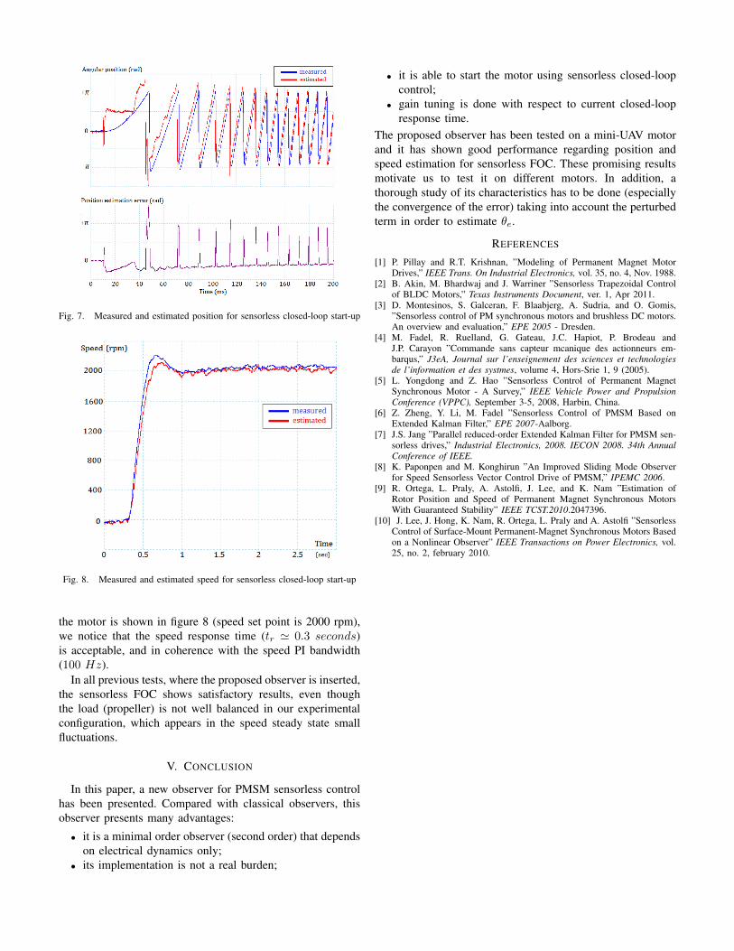
Fig. 7. Measured and estimated position for sensorless closed-loop start-up
Fig. 8. Measured and estimated speed for sensorless closed-loop start-up
the motor is shown in figure 8 (speed set point is 2000 rpm),we notice that the speed response time (tr ' 0.3 seconds)is acceptable, and in coherence with the speed PI bandwidth(100 Hz).
In all previous tests, where the proposed observer is inserted,the sensorless FOC shows satisfactory results, even thoughthe load (propeller) is not well balanced in our experimentalconfiguration, which appears in the speed steady state smallfluctuations.
V. CONCLUSION
In this paper, a new observer for PMSM sensorless controlhas been presented. Compared with classical observers, thisobserver presents many advantages:
• it is a minimal order observer (second order) that dependson electrical dynamics only;
• its implementation is not a real burden;
• it is able to start the motor using sensorless closed-loopcontrol;
• gain tuning is done with respect to current closed-loopresponse time.
The proposed observer has been tested on a mini-UAV motorand it has shown good performance regarding position andspeed estimation for sensorless FOC. These promising resultsmotivate us to test it on different motors. In addition, athorough study of its characteristics has to be done (especiallythe convergence of the error) taking into account the perturbedterm in order to estimate θe.
REFERENCES
[1] P. Pillay and R.T. Krishnan, ”Modeling of Permanent Magnet MotorDrives,” IEEE Trans. On Industrial Electronics, vol. 35, no. 4, Nov. 1988.
[2] B. Akin, M. Bhardwaj and J. Warriner ”Sensorless Trapezoidal Controlof BLDC Motors,” Texas Instruments Document, ver. 1, Apr 2011.
[3] D. Montesinos, S. Galceran, F. Blaabjerg, A. Sudria, and O. Gomis,”Sensorless control of PM synchronous motors and brushless DC motors.An overview and evaluation,” EPE 2005 - Dresden.
[4] M. Fadel, R. Ruelland, G. Gateau, J.C. Hapiot, P. Brodeau andJ.P. Carayon ”Commande sans capteur mcanique des actionneurs em-barqus,” J3eA, Journal sur l’enseignement des sciences et technologiesde l’information et des systmes, volume 4, Hors-Srie 1, 9 (2005).
[5] L. Yongdong and Z. Hao ”Sensorless Control of Permanent MagnetSynchronous Motor - A Survey,” IEEE Vehicle Power and PropulsionConference (VPPC), September 3-5, 2008, Harbin, China.
[6] Z. Zheng, Y. Li, M. Fadel ”Sensorless Control of PMSM Based onExtended Kalman Filter,” EPE 2007-Aalborg.
[7] J.S. Jang ”Parallel reduced-order Extended Kalman Filter for PMSM sen-sorless drives,” Industrial Electronics, 2008. IECON 2008. 34th AnnualConference of IEEE.
[8] K. Paponpen and M. Konghirun ”An Improved Sliding Mode Observerfor Speed Sensorless Vector Control Drive of PMSM,” IPEMC 2006.
[9] R. Ortega, L. Praly, A. Astolfi, J. Lee, and K. Nam ”Estimation ofRotor Position and Speed of Permanent Magnet Synchronous MotorsWith Guaranteed Stability” IEEE TCST.2010.2047396.
[10] J. Lee, J. Hong, K. Nam, R. Ortega, L. Praly and A. Astolfi ”SensorlessControl of Surface-Mount Permanent-Magnet Synchronous Motors Basedon a Nonlinear Observer” IEEE Transactions on Power Electronics, vol.25, no. 2, february 2010.