Embed Size (px)
Citation preview
A Real-Time Performance Evaluation of TightlyCoupled LTE Wi-Fi Radio Access NetworksThomas Valerrian Pasca S, Sumanta Patro, Bheemarjuna Reddy Tamma, and Antony Franklin A
Department of Computer Science and Engineering, IIT HyderabadEmail: [cs13p1002, cs15mtech01005, tbr, antony.franklin]@iith.ac.in
Abstract—A tight coupling of LTE and Wi-Fi interfaces canbe achieved by integrating them at their radio protocol stacks.LTE and Wi-Fi radio level integration with IPSec tunnel (LWIP)was introduced by 3GPP as part of Rel-13. This tighter levelof interworking replaces the traditional way of cellular-Wi-Fiinterworking through a packet gateway and it can react to thedynamic changes in the wireless link quality. In this paper, wepresent a variant of LWIP prototype that works with commercialUE (Nexus 5). The developed LWIP prototype uses OpenAirInter-face (OAI) for LTE network and Cisco Access Point (AP) as Wi-Fi AP. We also present the design and implementation of LWIPprototype and interesting results for tight interworking of LTEand Wi-Fi at IP level. We have evaluated the LWIP performancewith different Link Aggregation Strategies (LAS) using bothUDP and TCP. We have observed that, in a highly loadedWi-Fi channel, when LWIP employs Wi-Fi only in Downlink(WoD) LAS, then sum of individual TCP flow throughput hasimproved by 28% as compared to LWIP operating with FlowSplit (FS) LAS. We have enumerated the challenges which hasto be addressed in LWIP to reap the maximum benefits.
I. INTRODUCTION
The Cisco VNI forecast elucidates that the data trafficgenerated by mobile devices is growing at an exponential rate,than it could ever imagine. As per [1], monthly mobile datatraffic will reach 49 exabytes by 2021, up from 7.2 exabytesper month in 2016. Operators look for a best solution to caterthis ever increasing demand. LTE–Wi-Fi interworking is onesuch technology which can serve this high data requirement.The problem which exists with LTE–Wi-Fi interworking istheir underlying interworking architecture. The interworkingfrom Rel-8 to Rel-11 is completely realized through offloading(i.e., moving a flow completely from LTE interface to Wi-Fiinterface and vice-versa). Such flow offloading requires achange in the flow route from the cellular core network tothe Wi-Fi network. Frequent flow routing across LTE and Wi-Fi networks at Evolved Packet Core (EPC) is inefficient fordense small cell deployments. To address this problem, and toserve delay bounded services and to increase the flexibilityin offloading, there is a necessity for these two radios towork much closer. Hence, LTE–Wi-Fi radio level integrationwith IPSec Tunnel (LWIP) has evolved realizing a tighterintegration by associating a Wi-Fi radio next to LTE radiowhich facilitates an enhanced control over both the radios.LWIP realizes the interworking benefit at link level for betterquality of service with seamless flow mobility across LTE andWi-Fi interfaces. LWIP has the following advantages:
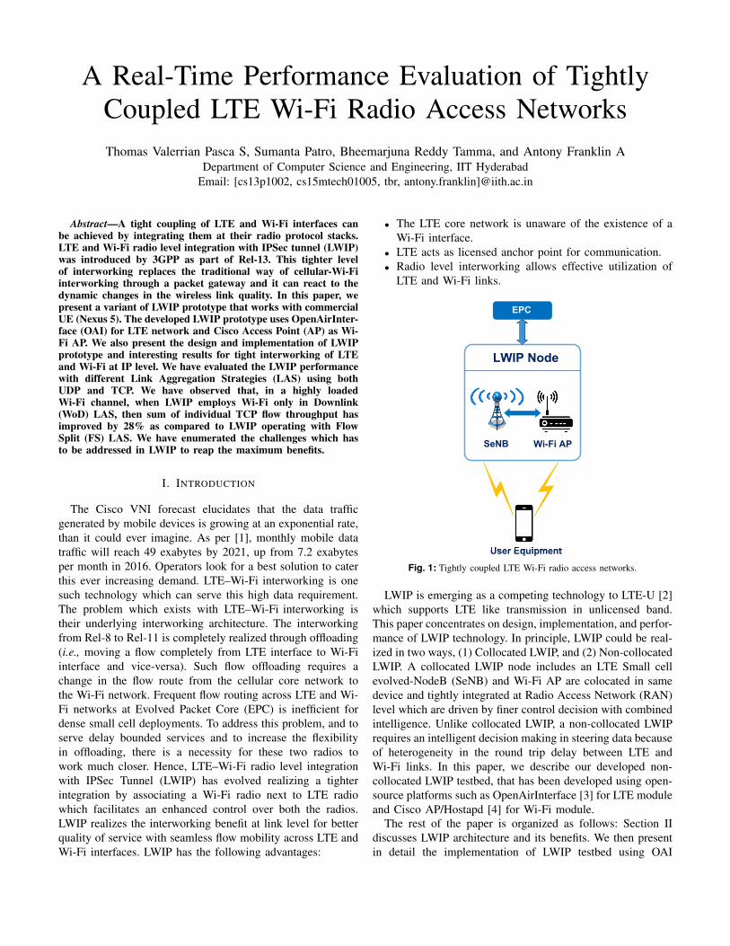
• The LTE core network is unaware of the existence of aWi-Fi interface.
• LTE acts as licensed anchor point for communication.• Radio level interworking allows effective utilization of
LTE and Wi-Fi links.
LWIP Node
SeNB Wi-Fi AP
EPC
User Equipment
Fig. 1: Tightly coupled LTE Wi-Fi radio access networks.
LWIP is emerging as a competing technology to LTE-U [2]which supports LTE like transmission in unlicensed band.This paper concentrates on design, implementation, and perfor-mance of LWIP technology. In principle, LWIP could be real-ized in two ways, (1) Collocated LWIP, and (2) Non-collocatedLWIP. A collocated LWIP node includes an LTE Small cellevolved-NodeB (SeNB) and Wi-Fi AP are colocated in samedevice and tightly integrated at Radio Access Network (RAN)level which are driven by finer control decision with combinedintelligence. Unlike collocated LWIP, a non-collocated LWIPrequires an intelligent decision making in steering data becauseof heterogeneity in the round trip delay between LTE andWi-Fi links. In this paper, we describe our developed non-collocated LWIP testbed, that has been developed using open-source platforms such as OpenAirInterface [3] for LTE moduleand Cisco AP/Hostapd [4] for Wi-Fi module.
The rest of the paper is organized as follows: Section IIdiscusses LWIP architecture and its benefits. We then presentin detail the implementation of LWIP testbed using OAI
in Section III. In Section IV, LWIP testbed performance isevaluated by employing different Link Aggregation Strategies(LAS). Finally, in Section V, we present concluding remarks.
II. ARCHITECTURE PROPOSAL AND STANDARDS
Third-Generation Partnership Project (3GPP) has shed lighton standardization of data offloading to WLAN from Release8 onwards. They include, Rel-8: PMIP based mobility andAccess Network Discovery and Selection Function (ANDSF),Rel-9: enhanced ANDSF (eANDSF), Rel-10: IP Flow mobility(IFOM), Rel-11: location based selection of gateway forWLAN, and Rel-12: WLAN network selection, Multiple PDNconnections, and IP preservation. All these schemes focuson realizing LTE–Wi-Fi interworking through Evolved PacketCore (EPC) core (such as, at Serving Gateway (S-GW) andPacket Gateway (P-GW)). The granularity of offloading inthese schemes is at flow level i.e., moving a flow completelyfrom one interface to another interface. These gateway basedsolutions are not quick in the case of user mobility, anddynamic channel variations (e.g., shadowing and fading). Toquash from this inefficiency in regulating traffic flows acrossLTE and Wi-Fi networks, finer control over interfaces isrequired, it could be achieved only if the decision makingentity for offloading is adjacent to RAN part of LTE and Wi-Finetworks. This requirement has impelled the decision makingentity all the way from the EPC to SeNB, which ensures atight coupling between LTE and Wi-Fi RANs.
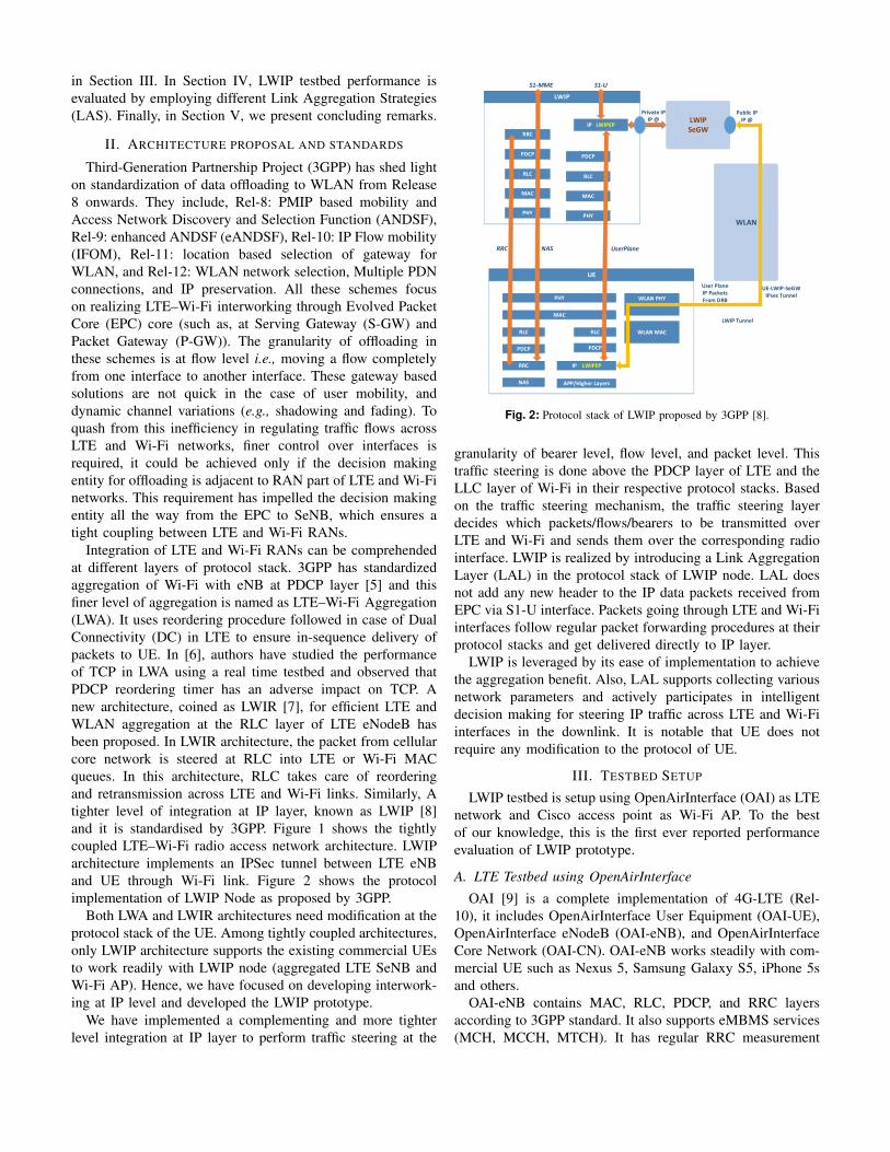
Integration of LTE and Wi-Fi RANs can be comprehendedat different layers of protocol stack. 3GPP has standardizedaggregation of Wi-Fi with eNB at PDCP layer [5] and thisfiner level of aggregation is named as LTE–Wi-Fi Aggregation(LWA). It uses reordering procedure followed in case of DualConnectivity (DC) in LTE to ensure in-sequence delivery ofpackets to UE. In [6], authors have studied the performanceof TCP in LWA using a real time testbed and observed thatPDCP reordering timer has an adverse impact on TCP. Anew architecture, coined as LWIR [7], for efficient LTE andWLAN aggregation at the RLC layer of LTE eNodeB hasbeen proposed. In LWIR architecture, the packet from cellularcore network is steered at RLC into LTE or Wi-Fi MACqueues. In this architecture, RLC takes care of reorderingand retransmission across LTE and Wi-Fi links. Similarly, Atighter level of integration at IP layer, known as LWIP [8]and it is standardised by 3GPP. Figure 1 shows the tightlycoupled LTE–Wi-Fi radio access network architecture. LWIParchitecture implements an IPSec tunnel between LTE eNBand UE through Wi-Fi link. Figure 2 shows the protocolimplementation of LWIP Node as proposed by 3GPP.
Both LWA and LWIR architectures need modification at theprotocol stack of the UE. Among tightly coupled architectures,only LWIP architecture supports the existing commercial UEsto work readily with LWIP node (aggregated LTE SeNB andWi-Fi AP). Hence, we have focused on developing interwork-ing at IP level and developed the LWIP prototype.
We have implemented a complementing and more tighterlevel integration at IP layer to perform traffic steering at the
PDCP
RLC
MAC
PHY
S1-U
RRC
PDCP
RLC
MAC
PHY
IP LWIPEP
RLC
PDCP
IP LWIPEP
PHY
MAC
RLC
PDCP
RRC
APP/Higher Layers
WLAN PHY
WLAN MAC
LWIP SeGW
WLAN
NAS
S1-MME
RRC NAS UserPlane
Private IP IP @
Public IP IP @
User Plane IP Packets From DRB
LWIP Tunnel
UE-LWIP-SeGWIPsec Tunnel
Fig. 2: Protocol stack of LWIP proposed by 3GPP [8].
granularity of bearer level, flow level, and packet level. Thistraffic steering is done above the PDCP layer of LTE and theLLC layer of Wi-Fi in their respective protocol stacks. Basedon the traffic steering mechanism, the traffic steering layerdecides which packets/flows/bearers to be transmitted overLTE and Wi-Fi and sends them over the corresponding radiointerface. LWIP is realized by introducing a Link AggregationLayer (LAL) in the protocol stack of LWIP node. LAL doesnot add any new header to the IP data packets received fromEPC via S1-U interface. Packets going through LTE and Wi-Fiinterfaces follow regular packet forwarding procedures at theirprotocol stacks and get delivered directly to IP layer.
LWIP is leveraged by its ease of implementation to achievethe aggregation benefit. Also, LAL supports collecting variousnetwork parameters and actively participates in intelligentdecision making for steering IP traffic across LTE and Wi-Fiinterfaces in the downlink. It is notable that UE does notrequire any modification to the protocol of UE.
III. TESTBED SETUP
LWIP testbed is setup using OpenAirInterface (OAI) as LTEnetwork and Cisco access point as Wi-Fi AP. To the bestof our knowledge, this is the first ever reported performanceevaluation of LWIP prototype.
A. LTE Testbed using OpenAirInterface
OAI [9] is a complete implementation of 4G-LTE (Rel-10), it includes OpenAirInterface User Equipment (OAI-UE),OpenAirInterface eNodeB (OAI-eNB), and OpenAirInterfaceCore Network (OAI-CN). OAI-eNB works steadily with com-mercial UE such as Nexus 5, Samsung Galaxy S5, iPhone 5sand others.
OAI-eNB contains MAC, RLC, PDCP, and RRC layersaccording to 3GPP standard. It also supports eMBMS services(MCH, MCCH, MTCH). It has regular RRC measurement
LWIP Node
UE
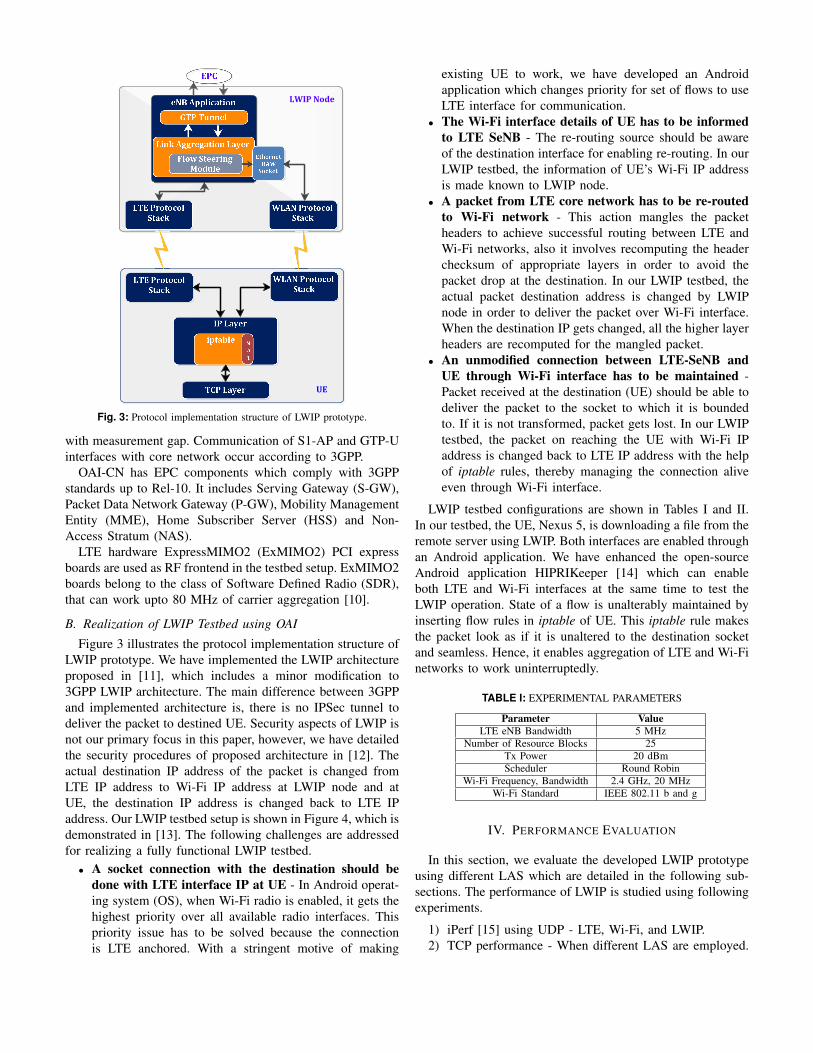
Fig. 3: Protocol implementation structure of LWIP prototype.
with measurement gap. Communication of S1-AP and GTP-Uinterfaces with core network occur according to 3GPP.
OAI-CN has EPC components which comply with 3GPPstandards up to Rel-10. It includes Serving Gateway (S-GW),Packet Data Network Gateway (P-GW), Mobility ManagementEntity (MME), Home Subscriber Server (HSS) and Non-Access Stratum (NAS).
LTE hardware ExpressMIMO2 (ExMIMO2) PCI expressboards are used as RF frontend in the testbed setup. ExMIMO2boards belong to the class of Software Defined Radio (SDR),that can work upto 80 MHz of carrier aggregation [10].
B. Realization of LWIP Testbed using OAI
Figure 3 illustrates the protocol implementation structure ofLWIP prototype. We have implemented the LWIP architectureproposed in [11], which includes a minor modification to3GPP LWIP architecture. The main difference between 3GPPand implemented architecture is, there is no IPSec tunnel todeliver the packet to destined UE. Security aspects of LWIP isnot our primary focus in this paper, however, we have detailedthe security procedures of proposed architecture in [12]. Theactual destination IP address of the packet is changed fromLTE IP address to Wi-Fi IP address at LWIP node and atUE, the destination IP address is changed back to LTE IPaddress. Our LWIP testbed setup is shown in Figure 4, which isdemonstrated in [13]. The following challenges are addressedfor realizing a fully functional LWIP testbed.
• A socket connection with the destination should bedone with LTE interface IP at UE - In Android operat-ing system (OS), when Wi-Fi radio is enabled, it gets thehighest priority over all available radio interfaces. Thispriority issue has to be solved because the connectionis LTE anchored. With a stringent motive of making
existing UE to work, we have developed an Androidapplication which changes priority for set of flows to useLTE interface for communication.
• The Wi-Fi interface details of UE has to be informedto LTE SeNB - The re-routing source should be awareof the destination interface for enabling re-routing. In ourLWIP testbed, the information of UE’s Wi-Fi IP addressis made known to LWIP node.
• A packet from LTE core network has to be re-routedto Wi-Fi network - This action mangles the packetheaders to achieve successful routing between LTE andWi-Fi networks, also it involves recomputing the headerchecksum of appropriate layers in order to avoid thepacket drop at the destination. In our LWIP testbed, theactual packet destination address is changed by LWIPnode in order to deliver the packet over Wi-Fi interface.When the destination IP gets changed, all the higher layerheaders are recomputed for the mangled packet.
• An unmodified connection between LTE-SeNB andUE through Wi-Fi interface has to be maintained -Packet received at the destination (UE) should be able todeliver the packet to the socket to which it is boundedto. If it is not transformed, packet gets lost. In our LWIPtestbed, the packet on reaching the UE with Wi-Fi IPaddress is changed back to LTE IP address with the helpof iptable rules, thereby managing the connection aliveeven through Wi-Fi interface.
LWIP testbed configurations are shown in Tables I and II.In our testbed, the UE, Nexus 5, is downloading a file from theremote server using LWIP. Both interfaces are enabled throughan Android application. We have enhanced the open-sourceAndroid application HIPRIKeeper [14] which can enableboth LTE and Wi-Fi interfaces at the same time to test theLWIP operation. State of a flow is unalterably maintained byinserting flow rules in iptable of UE. This iptable rule makesthe packet look as if it is unaltered to the destination socketand seamless. Hence, it enables aggregation of LTE and Wi-Finetworks to work uninterruptedly.
TABLE I: EXPERIMENTAL PARAMETERS
Parameter ValueLTE eNB Bandwidth 5 MHz
Number of Resource Blocks 25Tx Power 20 dBmScheduler Round Robin
Wi-Fi Frequency, Bandwidth 2.4 GHz, 20 MHzWi-Fi Standard IEEE 802.11 b and g
IV. PERFORMANCE EVALUATION
In this section, we evaluate the developed LWIP prototypeusing different LAS which are detailed in the following sub-sections. The performance of LWIP is studied using followingexperiments.
1) iPerf [15] using UDP - LTE, Wi-Fi, and LWIP.2) TCP performance - When different LAS are employed.
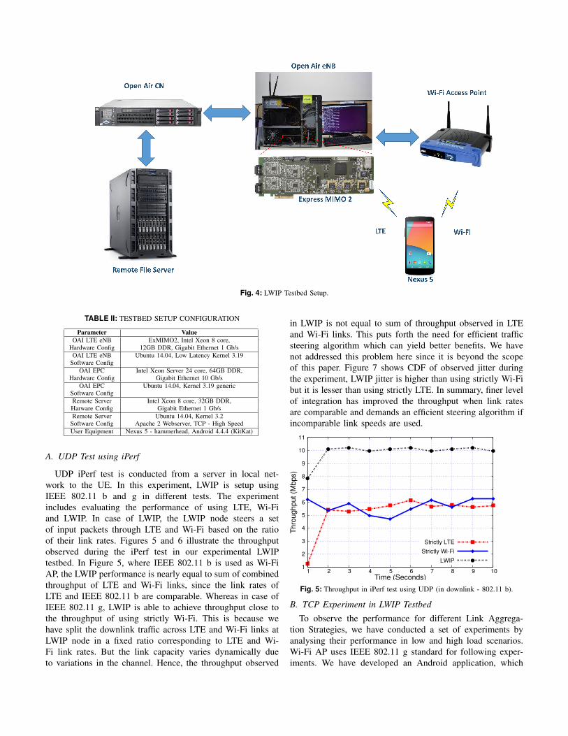
Fig. 4: LWIP Testbed Setup.
TABLE II: TESTBED SETUP CONFIGURATION
Parameter ValueOAI LTE eNB ExMIMO2, Intel Xeon 8 core,
Hardware Config 12GB DDR, Gigabit Ethernet 1 Gb/sOAI LTE eNB Ubuntu 14.04, Low Latency Kernel 3.19
Software ConfigOAI EPC Intel Xeon Server 24 core, 64GB DDR,
Hardware Config Gigabit Ethernet 10 Gb/sOAI EPC Ubuntu 14.04, Kernel 3.19 generic
Software ConfigRemote Server Intel Xeon 8 core, 32GB DDR,Harware Config Gigabit Ethernet 1 Gb/sRemote Server Ubuntu 14.04, Kernel 3.2
Software Config Apache 2 Webserver, TCP - High SpeedUser Equipment Nexus 5 - hammerhead, Android 4.4.4 (KitKat)
A. UDP Test using iPerf
UDP iPerf test is conducted from a server in local net-work to the UE. In this experiment, LWIP is setup usingIEEE 802.11 b and g in different tests. The experimentincludes evaluating the performance of using LTE, Wi-Fiand LWIP. In case of LWIP, the LWIP node steers a setof input packets through LTE and Wi-Fi based on the ratioof their link rates. Figures 5 and 6 illustrate the throughputobserved during the iPerf test in our experimental LWIPtestbed. In Figure 5, where IEEE 802.11 b is used as Wi-FiAP, the LWIP performance is nearly equal to sum of combinedthroughput of LTE and Wi-Fi links, since the link rates ofLTE and IEEE 802.11 b are comparable. Whereas in case ofIEEE 802.11 g, LWIP is able to achieve throughput close tothe throughput of using strictly Wi-Fi. This is because wehave split the downlink traffic across LTE and Wi-Fi links atLWIP node in a fixed ratio corresponding to LTE and Wi-Fi link rates. But the link capacity varies dynamically dueto variations in the channel. Hence, the throughput observed
in LWIP is not equal to sum of throughput observed in LTEand Wi-Fi links. This puts forth the need for efficient trafficsteering algorithm which can yield better benefits. We havenot addressed this problem here since it is beyond the scopeof this paper. Figure 7 shows CDF of observed jitter duringthe experiment, LWIP jitter is higher than using strictly Wi-Fibut it is lesser than using strictly LTE. In summary, finer levelof integration has improved the throughput when link ratesare comparable and demands an efficient steering algorithm ifincomparable link speeds are used.
1
2
3
4
5
6
7
8
9
10
11
1 2 3 4 5 6 7 8 9 10
Th
rou
gh
pu
t (M
bp
s)
Time (Seconds)
Strictly LTE
Strictly Wi-Fi
LWIP
Fig. 5: Throughput in iPerf test using UDP (in downlink - 802.11 b).
B. TCP Experiment in LWIP Testbed
To observe the performance for different Link Aggrega-tion Strategies, we have conducted a set of experiments byanalysing their performance in low and high load scenarios.Wi-Fi AP uses IEEE 802.11 g standard for following exper-iments. We have developed an Android application, which

0
5
10
15
20
25
30
35
1 2 3 4 5 6 7 8 9 10
Thro
ugh
put
(Mbp
s)
Time (Seconds)
Strictly LTE
Strictly Wi-Fi
LWIP
Fig. 6: Throughput in iPerf test using UDP (in downlink - 802.11 g).
0
0.2
0.4
0.6
0.8
1
0 1 2 3 4 5 6 7
CD
F
Jitter( Milli Seconds)
Strictly LTE
Strictly Wi-Fi
LWIP
Fig. 7: Jitter CDF for iPerf test.
downloads two files simultaneously from a remote server andmeasures their throughputs. The UE performance is evaluatedusing the following LAS,
• LTE NoLAS: Two flows are simultaneously downloadedthrough LTE.
• Wi-Fi NoLAS: Two flows are simultaneously down-loaded through Wi-Fi.
• FS-LAS: Flow split enables one flow to be downloadedthrough LTE and other through Wi-Fi.
• WoD-LAS: WiFi only in Downlink enables both theflows to use Wi-Fi for downlink and the correspondingTCP ACKs are sent through LTE in uplink.
TCP Experiment 1 - Lightly Loaded Scenario: Thesetup consists of a UE and a LWIP node with backgroundtransmission in Wi-Fi channel (observed channel load is 8%).Now, UE downloads two files from the remote server usingdifferent LAS. We have downloaded files of different sizes viz.,16 and 32 MB. Figure 8 shows the throughput observed in caseof different file downloads. It can be observed that FS-LAS hasachieved higher throughput, since it effectively aggregates theLTE and Wi-Fi links. Also it is better compared to WoD-LASbecause of the type of steering it employs. Figure 9 showsthat all the LAS employed utilizes Wi-Fi link at its maximumlink rate. Time to download a file using different LAS isshown in Figure 10. Even though the throughput of FS-LASand WoD-LAS are comparable, the time to download a file
through FS-LAS incurs longer time than WoD-LAS becausefile download through LTE interface incurs longer downloadtime.
0
5
10
15
20
25
30
35
16 MB 32 MB
Thro
ughp
ut
(Mb
ps)
File Size
LTE NoLASWi-Fi NoLAS
FS-LASWoD-LAS
Fig. 8: Overall Throughput observed for 16 MB and 32 MB file sizes withlow contention.
0
5
10
15
20
25
30
35
16 MB 32 MB
Th
rou
gh
put
(Mb
ps)
File Size
Wi-Fi NoLASFS-LAS
WoD-LAS
Fig. 9: Throughput of Wi-Fi observed for 16 MB and 32 MB file sizes withlow contention.
0
20
40
60
80
100
LTE NoLAS Wi-Fi NoLAS FS-LAS WoD-LAS
Do
wn
load
Tim
e (
Se
c)
Flow-1
Flow-2
Fig. 10: Time to download a 32 MB file with low contention.
TCP Experiment 2 - Heavily Loaded Scenario: In thissetup, for creating a heavily loaded condition, we have usedfive laptops, each of those streams video at high bit rate(900 kbps UDP stream per device) to an AP operating inthe same Wi-Fi channel of LWIP node. This newly introduceload is in addition to existing 8% background Wi-Fi channel
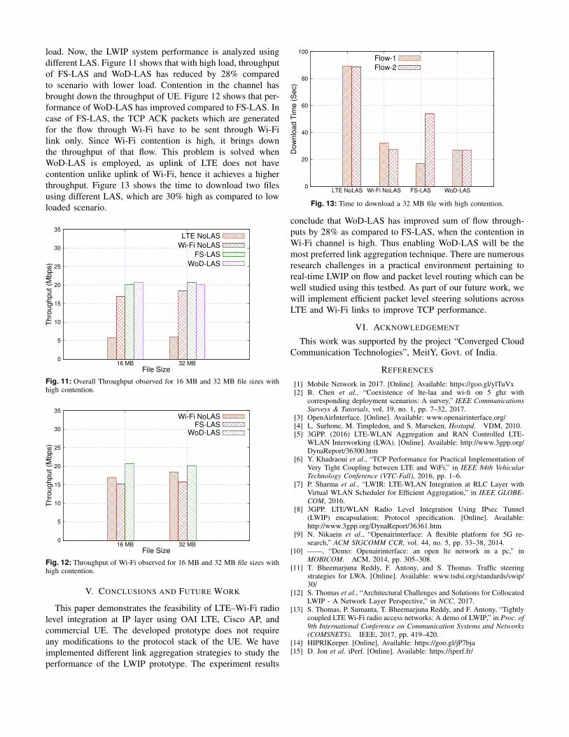
load. Now, the LWIP system performance is analyzed usingdifferent LAS. Figure 11 shows that with high load, throughputof FS-LAS and WoD-LAS has reduced by 28% comparedto scenario with lower load. Contention in the channel hasbrought down the throughput of UE. Figure 12 shows that per-formance of WoD-LAS has improved compared to FS-LAS. Incase of FS-LAS, the TCP ACK packets which are generatedfor the flow through Wi-Fi have to be sent through Wi-Filink only. Since Wi-Fi contention is high, it brings downthe throughput of that flow. This problem is solved whenWoD-LAS is employed, as uplink of LTE does not havecontention unlike uplink of Wi-Fi, hence it achieves a higherthroughput. Figure 13 shows the time to download two filesusing different LAS, which are 30% high as compared to lowloaded scenario.
0
5
10
15
20
25
30
35
16 MB 32 MB
Th
rou
gh
put
(Mb
ps)
File Size
LTE NoLAS
Wi-Fi NoLAS
FS-LAS
WoD-LAS
Fig. 11: Overall Throughput observed for 16 MB and 32 MB file sizes withhigh contention.
0
5
10
15
20
25
30
35
16 MB 32 MB
Th
rou
ghp
ut
(Mbp
s)
File Size
Wi-Fi NoLASFS-LAS
WoD-LAS
Fig. 12: Throughput of Wi-Fi observed for 16 MB and 32 MB file sizes withhigh contention.
V. CONCLUSIONS AND FUTURE WORK
This paper demonstrates the feasibility of LTE–Wi-Fi radiolevel integration at IP layer using OAI LTE, Cisco AP, andcommercial UE. The developed prototype does not requireany modifications to the protocol stack of the UE. We haveimplemented different link aggregation strategies to study theperformance of the LWIP prototype. The experiment results
0
20
40
60
80
100
LTE NoLAS Wi-Fi NoLAS FS-LAS WoD-LAS
Dow
nlo
ad T
ime (
Sec)
Flow-1
Flow-2
Fig. 13: Time to download a 32 MB file with high contention.
conclude that WoD-LAS has improved sum of flow through-puts by 28% as compared to FS-LAS, when the contention inWi-Fi channel is high. Thus enabling WoD-LAS will be themost preferred link aggregation technique. There are numerousresearch challenges in a practical environment pertaining toreal-time LWIP on flow and packet level routing which can bewell studied using this testbed. As part of our future work, wewill implement efficient packet level steering solutions acrossLTE and Wi-Fi links to improve TCP performance.
VI. ACKNOWLEDGEMENT
This work was supported by the project “Converged CloudCommunication Technologies”, MeitY, Govt. of India.
REFERENCES
[1] Mobile Network in 2017. [Online]. Available: https://goo.gl/ylTuVx[2] B. Chen et al., “Coexistence of lte-laa and wi-fi on 5 ghz with
corresponding deployment scenarios: A survey,” IEEE CommunicationsSurveys & Tutorials, vol. 19, no. 1, pp. 7–32, 2017.
[3] OpenAirInterface. [Online]. Available: www.openairinterface.org/[4] L. Surhone, M. Timpledon, and S. Marseken, Hostapd. VDM, 2010.[5] 3GPP. (2016) LTE-WLAN Aggregation and RAN Controlled LTE-
WLAN Interworking (LWA). [Online]. Available: http://www.3gpp.org/DynaReport/36300.htm
[6] Y. Khadraoui et al., “TCP Performance for Practical Implementation ofVery Tight Coupling between LTE and WiFi,” in IEEE 84th VehicularTechnology Conference (VTC-Fall), 2016, pp. 1–6.
[7] P. Sharma et al., “LWIR: LTE-WLAN Integration at RLC Layer withVirtual WLAN Scheduler for Efficient Aggregation,” in IEEE GLOBE-COM, 2016.
[8] 3GPP. LTE/WLAN Radio Level Integration Using IPsec Tunnel(LWIP) encapsulation; Protocol specification. [Online]. Available:http://www.3gpp.org/DynaReport/36361.htm
[9] N. Nikaein et al., “Openairinterface: A flexible platform for 5G re-search,” ACM SIGCOMM CCR, vol. 44, no. 5, pp. 33–38, 2014.
[10] ——, “Demo: Openairinterface: an open lte network in a pc,” inMOBICOM. ACM, 2014, pp. 305–308.
[11] T. Bheemarjuna Reddy, F. Antony, and S. Thomas. Traffic steeringstrategies for LWA. [Online]. Available: www.tsdsi.org/standards/swip/30/
[12] S. Thomas et al., “Architectural Challenges and Solutions for CollocatedLWIP - A Network Layer Perspective,” in NCC, 2017.
[13] S. Thomas, P. Sumanta, T. Bheemarjuna Reddy, and F. Antony, “Tightlycoupled LTE Wi-Fi radio access networks: A demo of LWIP,” in Proc. of9th International Conference on Communication Systems and Networks(COMSNETS). IEEE, 2017, pp. 419–420.
[14] HIPRIKeeper. [Online]. Available: https://goo.gl/jP7bja[15] D. Jon et al. iPerf. [Online]. Available: https://iperf.fr/