Embed Size (px)
Citation preview

A REPORT ON
PROJECT BASED LEARNING (PBL)
for
Second Year and Third Year Undergraduate Students of Mechanical and Automobile Engineering Departments
of MES’s Pillai College of Engineering, New Panvel
for the Academic Year 2017-2018 (EVEN Semesters)
Semesters – IV (CBCGS) & VI(CBSGS)
Objective—To enable the students to apply concepts of the present semester subjects (including those of previous
semesters) in the form of a design project based on certain application. It is hoped that it shall
eventually lead to a better learning experience as opposed to text-book learning.
A common topic is assigned to all students of the same year, to provide a common yardstick for
comparison and enable healthy competition among the different teams. The students work in groups
(maximum 5-6 students per group) and assign and distribute various aspects of work so as to realize the
project based on a timeline of about 2 months. Queries and doubts are clarified by interactions with the
PBL coordinators and subject experts. Student groups submit the PBL report during their
demonstrations on a specified date in front of the faculty members.
PBL Topics Conceptualised by—Dr. Priam Pillai, and Team (Shridhar Deshmukh, Amey Nijasure, Salim Jafri)
PBL Coordinators—M. Durga Rao and Shaligram Avinash
Judges for the PBL Demonstrations—All Mechanical and Automobile Engineering Faculty Members, including
Teaching Assistants.
PBL Topic for Second Year Mechanical/Automobile Engineering: FIDGET SPINNER
Fidget Spinners are toys that are little gyroscopes, which can spin at high speeds with little effort when
spun in someone’s hands. A basic fidget spinner consists of a usually two- or three-pronged (but can have up to six
prongs or more) design with a bearing in its centre circular pad. They are made from various materials including
brass, stainless steel, titanium, copper, aluminium, and plastic (see picture). Each fidget spinner also has two or
more weights on the outside that make it spin faster and stay balanced. Bearings and the moment of inertia can
vary to adjust for the design's spin time, vibration, and noise, causing unique sensory feedback.
Fig 1. Fidget spinners in the Project Lab.

By examining and studying fidget spinners, we can understand exponential decay, gyroscopic motion, friction,
inertia and much more.
In this project, students will design and fabricate their own fidget spinners using at least two different fabrication
techniques.
1. Students will design the spinner in SolidWorks and estimate its weight and moment of inertia. They will
optimize the spinner for aesthetics and uniqueness of design. (Stage 1—March 17th 2018)
2. Derive an equation for the angular velocity of the spinner as a function of the moment of inertia (I) and
bearing frictional damping (b). One can use conservation of angular momentum principles.
3. Select a proper bearing having minimum friction and explain.
4. Students will fabricate the spinner using any material of their choice using two different fabrication
techniques (3D printing, lathe, laser cutting, CNC machining etc) and will install a bearing with the
minimum amount of friction. (Stage 2—from points 2-4, April 7th 2018)
Design Parameters:
1. The maximum diameter of the spinner should be less than 70mm and the thickness should be less than
20 mm. It could be made by any suitable material.
2. Student should design and install a bearing over which the spinner will rotate. They should research proper
bearing installation techniques before finalizing their designs and fabrication. The spinner should spin with
minimum friction.
3. A rubber band will be used to give the spinner a suitable standard impulse to get it started. The rubber band
will need to either be hooked on one of the prongs of the spinner or attached to it in some other way.
Students should consider how the spinner will be attached to the rubber band.
4. The spinner should rotate for a minimum of 30 seconds for a standard input.
5. Bonus: Students should take a video recording with their phone (or use a non-contact tachometer) to
measure the angular velocity of the spinner and produce a graph of the angular velocity vs time for an
impulse input. They can estimate the decay time from the graph as well as the time constant and the
bearing frictional damping.
Fig 2: Setup to provide uniform input to the spinner. Students should ensure
that a rubber band can be attached to the spinner.
Some Considerations:
Angular Velocity and Exponential Decay: Some people play with fidget spinners in order to improve their spin time.
For many, spinning a fidget spinner is a lot less about fidgeting and a little more of a competition. If you have ever
spent any time doing this, then you likely understand that it's really hard to drastically improve the spin time and
angular velocity (speed) of your fidget spinner. It may make sense from a general perspective that spinning a
spinner twice as hard or twice as fast would result in double the spin time, but that isn't even close to what actually
happens. This is due to the principle of exponential decay. By observing how the frequency and thus the speed of a
fidget spinner changes over time, we are left with a graph that demonstrates some near-perfect exponential
behavior. Can you derive the equation of this graph (angular frequency vs time) from first principles? Can we use
this to estimate the bearing friction?
Gyroscopic Motion: Gyroscopes are spinning devices mounted on an axis used to provide stability to a body through
the resistance of motion due to rotational momentum. We can understand this principle when spinning a fidget
spinner. If we try to rotate the spinner in a way that is not parallel to its rotational axis, we feel resistance from the
spinner itself. Examining this in more detail, we are left with the principle of gyroscopic precession. We can see
this at work if we take a fidget spinner and try to tilt it forward. Instead of the spinner tilting forward as one would
like, it sort of tilts at a diagonal, relative to the direction the spinner is going. This diagonal rotation is a direct
result of gyroscopic precession. Gyroscopic precession is defined when a force is applied to a rotating body, a force
appears 90 degrees after the point of impact in the direction of rotation. This is the exact principle at play when
using a fidget spinner.
As is customary, students need to furnish a detailed report (preferably typed and printed), both in theory based on
reasoning, and also dealing in calculations where required. Students should provide pictures of fabrication process
as well as SolidWorks drawings and calculations. Neat labeled diagrams should also be included where necessary.
Related Subjects: Kinematics of Machinery, Machine Shop Practice-II.
Term-Work Marks Allocation for PBL:
KOM: 05 marks (out of 25)
MSP-II: 10 marks (out of 50)
As in the last academic session (odd semesters), we conducted online feedback of the Project Based Learning, as experienced by the SE and TE students, and the results were again found to be very satisfying. A majority of the students enjoyed this way of learning and found to be better as compared to conventional class-room learning. Students strongly felt that this method of learning should be continued in future academic sessions too.
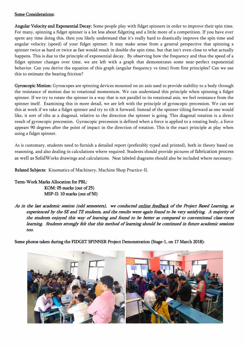
Some photos taken during the FIDGET SPINNER Project Demonstration (Stage-1, on 17 March 2018):

Some photos taken during the FIDGET SPINNER Project Demonstration (Stage-2, on 7th April 2018):
Before the actual demonstration of the student projects, a short faculty-training session was conducted by
Prof. Shridhar Deshmukh to make them aware of all the do’s and don’ts and update on the technical aspects.

Rubrics & Assessment Sheet (Stage 1, on 17 March 2018):

Rubrics & Assessment Sheet (Stage 2, on 7th April 2018):

PBL Topic for Third Year Mechanical/Automobile Engineering: FLAT PLATE SOLAR WATER HEATER
Sample Solar Water Heater and Solar Collector
Courtesy: pbs.org/designsquad and teachengineering.org
The Challenge:
Design and build a flat plate solar water heater, FPSWH, for a temperature rise of about 7 to 10oC/m length of
tube/pipe at 1000 W/m2 solar radiation intensity.
Students follow the engineering design process to: (a) build a FPSWH (b) test to see if it can raise the temperature
of water to desired level, and (c) use their testing results to improve the design and get as big a temperature change
as possible. They apply their understanding of the three forms of heat transfer conduction, convection and
radiation, as well as how they relate to energy efficiency. They calculate the efficiency of the solar water heaters
during initial and final tests.
Design Specifications:
Size of FPSWH: 0.3 m x 0.2 m
Source of Incident Radiations: Sun / Bulb (about 6-8 inches above panel)
Liquid to be heated: Water at room temperature initially
Liquid Inlet—Flow Parameters: Constant head and volume flow rate
Tube carrying liquid to be heated: Of any cross-section, size and material, may be bent into any
shape and any number of times. Should have only one inlet
and only one outlet (no branching of tubes permitted)
Total Time allotted for heat transfer: 10 minutes
Storage Tank: Not required. Water shall be collected in a separate
container (100 ml capacity)
Students need to take temperature measurements of outlet water from the tube after every filling of 100 ml in the
container, and plot graph of outlet water temperature versus time. The flexible hose connections to connect to
FPSWH at inlet and outlet shall be made available by the institute during demonstrations. The diameter of the
inlet and outlet tube apertures is approximately 1 cm. The reservoir supplying water will also be made available to
the students.

Stage I—Students are instructed to brainstorm ideas for the FPSWH designs (come up with at least 3 ideas, write or
draw all the ideas, can be as weird as possible—don’t get too critical at this stage), select the best design (most
promising one) based on various parameters, prepare a initial budget sheet with the cost and quantity of materials
needed for starting construction, prepare a detailed drawing that includes labeled materials and dimensions,
prepare CAD model of the SWH, materials budget worksheet (include quantity of each item), build the first
iteration of design, check for leaks (if any) before sealing the devices. (Date of Stage I demonstration: 17th March 2018, Saturday).
Stage II—Students are also advised to take time to make design modifications—try to focus on improving the
efficiency of the devices. Include any additional materials in the budget. Students need to furnish measurements
and calculations leading to temperature graphs (over time), efficiencies, total costs, cost/degree change, and cost per
% efficiency. (Date of Stage II demonstration: 11th April 2018, Wednesday).
Questions that need brainstorming and might affect the design of water heater:
1. What all are the components of FPSWH?
2. What material and colour should you make the tube and background?
3. How fast should the water flow through the tube? How might its speed affect its temperature?
4. How long should the tube carrying the liquid be? What problems may encounter if it is too long?
5. How thin should the cross section dimensions of the tube be?
6. What is the role of transparent cover on the top of the tubing panel?
7. How to tackle water leakage issues?
8. What should be the tube material? Has it any influence on the water heater performance?
9. What happens when water runs through the tube too quickly? What is the change observed if the
tube is pinched at one or more locations with tape or paper clips?
10. What is the effect of the change in height of the supply water cup?
11. Where did conduction, convection and radiation occur in your water heater?
12. Which features help a solar hot water use solar energy (light and infrared radiation) to heat water?
13. Engineers’ early ideas rarely work out perfectly. How does testing help them to improve a design?
14. Does concentration of the light to the required areas get the water hotter? How can this be made
possible?
15. How do we measure the volume of water, the temperature change, and the rate of water flow?
16. What is the overall cost of the water heater?
17. What materials did you use to construct the water heater?
18. How does the water heater performance get affected if air bubbles get clogged inside the tubes?
19. Is it best if the water that enters the water heater is cold, warm or hot? Why?
20. Why engineers would need to know the position of the water heater in relation to the incident
radiation? What is the best angle to be used?
21. How do we judge the size of a solar water heater panel for a family of 4 members?
22. Using the data to graph water temperature as a function of time, can you predict the water temperature
at an intermediate time step?
23. For a given incident radiation, tubing length and material, how can we maximize the heat transfer to
the liquid?
24. How can you evaluate cost per % of efficiency, and per degree change of water, for your water heater?
25. What are the trade-offs associated between efficiency and cost of the water heater?
As is customary, students need to furnish a detailed report (preferably typed and printed), both in theory based on
reasoning, and also dealing in calculations where required. Students should provide pictures of fabrication process
as well as SolidWorks drawings and calculations. Neat labelled diagrams should also be included where necessary.
Related Subjects: Metrology and Quality Engineering, Thermal and Fluid Power Engineering.
Term-Work Marks Allocation for PBL:
MQE: 05 marks (out of 25), TFPE: 5 marks (out of 25)

Some photos taken during the FPSWH Demonstration (Stage-1, on 17th March 2018):
Some photos taken during the FPSWH Demonstration (Stage-2, on 11th April 2018):


Rubrics & Assessment Sheet (Stage 1, on 17 March 2018):

Rubrics & Assessment Sheet (Stage 2, on 11 April 2018):