Embed Size (px)
Citation preview

IT 15 008
Examensarbete 30 hpMars 2015
A Requirements Elicitation Tool for Document Migration of Enterprise Content Management Systems
Kadir Yozgyur
Institutionen för informationsteknologiDepartment of Information Technology


Teknisk- naturvetenskaplig fakultet UTH-enheten Besöksadress: Ångströmlaboratoriet Lägerhyddsvägen 1 Hus 4, Plan 0 Postadress: Box 536 751 21 Uppsala Telefon: 018 – 471 30 03 Telefax: 018 – 471 30 00 Hemsida: http://www.teknat.uu.se/student
Abstract
A Requirements Elicitation Tool for DocumentMigration of Enterprise Content Management Systems
Kadir Yozgyur
Requirements Engineering (RE) is the area of Software Engineering that deals with finding, analysing, and structuring requirements from stakeholders of a project. Requirements Elicitation (RL) constitutes arguably the most crucial activities of Requirements Engineering. It is concerned with collecting, searching for, and elaborating requirements from stakeholders. The aim of this work is to provide a RL tool to improve the quality of requirements by enabling increased user participation, easing the effects of time constraints, and providing a common recording medium. The subject area selected for this thesis implementation is the elicitation for migrating physical documents into an ECM system that is being built. Requirements Interchange Format (ReqIF) is used as the underlying data model to rely on a solid standard. AJAX technologies and several JavaScript libraries are used together to create a smooth User Interface.
Tryckt av: Reprocentralen ITCIT 15 008Examinator: Ivan ChristoffÄmnesgranskare: Anders JanssonHandledare: Liu Qin

Contents
Abstract i
Contents ii
List of Figures iv
List of Tables v
Abbreviations vi
1 Introduction 1
1.1 A Definition: Requirements Elicitation . . . . . . . . . . . . . . . . . . 21.2 Role of Requirements Elicitation . . . . . . . . . . . . . . . . . . . . . 31.3 Research Focus . . . . . . . . . . . . . . . . . . . . . . . . . . . . . . 4
1.3.1 User Involvement . . . . . . . . . . . . . . . . . . . . . . . . . 41.3.2 Application Area . . . . . . . . . . . . . . . . . . . . . . . . . 5
2 Literature Review 6
2.1 Introduction . . . . . . . . . . . . . . . . . . . . . . . . . . . . . . . . 62.1.1 Requirements Elicitation Techniques . . . . . . . . . . . . . . 62.1.2 Requirement Elicitation Methodologies . . . . . . . . . . . . . 8
3 Project Design 10
3.1 Project Domain . . . . . . . . . . . . . . . . . . . . . . . . . . . . . . 103.2 Objectives . . . . . . . . . . . . . . . . . . . . . . . . . . . . . . . . . 11
3.2.1 Improving Quality of Requirements . . . . . . . . . . . . . . . 113.2.2 Time Factors . . . . . . . . . . . . . . . . . . . . . . . . . . . 133.2.3 Providing a Recording and Observation Medium . . . . . . . . 15
3.3 Design . . . . . . . . . . . . . . . . . . . . . . . . . . . . . . . . . . . 153.3.1 Process Flow . . . . . . . . . . . . . . . . . . . . . . . . . . . 163.3.2 Meeting Structure and Tool Workflow . . . . . . . . . . . . . . 17
3.4 Technical Choices . . . . . . . . . . . . . . . . . . . . . . . . . . . . . 183.4.1 Model: ReqIF Standard & Eclipse Requirement Modeling Frame-
work . . . . . . . . . . . . . . . . . . . . . . . . . . . . . . . 193.4.1.1 Eclipse Requirement Modeling Framework GUI: ProR 20
ii

Contents iii
3.4.2 Client-side: AJAX, JSON, and JavaScript . . . . . . . . . . . . 203.4.3 Server-side: Java Servlets & Jackson . . . . . . . . . . . . . . 21
4 Project Implementation 25
4.1 Overall Architecture . . . . . . . . . . . . . . . . . . . . . . . . . . . 254.2 Data Model . . . . . . . . . . . . . . . . . . . . . . . . . . . . . . . . 254.3 Server-side Implementation . . . . . . . . . . . . . . . . . . . . . . . . 294.4 Client-side Implementation . . . . . . . . . . . . . . . . . . . . . . . . 304.5 Technical Issues Encountered . . . . . . . . . . . . . . . . . . . . . . . 34
4.5.1 Data Model: ReqIF & View . . . . . . . . . . . . . . . . . . . 344.5.2 JSON . . . . . . . . . . . . . . . . . . . . . . . . . . . . . . . 354.5.3 Customizing JointJS . . . . . . . . . . . . . . . . . . . . . . . 36
5 Tests 42
5.1 Test Design . . . . . . . . . . . . . . . . . . . . . . . . . . . . . . . . 425.1.1 Identifying Risks . . . . . . . . . . . . . . . . . . . . . . . . . 425.1.2 Test Suites . . . . . . . . . . . . . . . . . . . . . . . . . . . . 435.1.3 Test Cases and Scenarios . . . . . . . . . . . . . . . . . . . . . 44
5.2 Results . . . . . . . . . . . . . . . . . . . . . . . . . . . . . . . . . . . 47
6 Further Research Roadmap 52
7 Conclusion 54
A Implementation Code 55
Bibliography 70

List of Figures
3.1 Overall process flow with the proposed tool . . . . . . . . . . . . . . . 163.2 An example meeting workflow with the proposed tool . . . . . . . . . . 173.3 GUI grids mock-up . . . . . . . . . . . . . . . . . . . . . . . . . . . . 223.4 Requirement links mock-up . . . . . . . . . . . . . . . . . . . . . . . . 233.5 Diagram mock-up . . . . . . . . . . . . . . . . . . . . . . . . . . . . . 24
4.1 Overall architecture . . . . . . . . . . . . . . . . . . . . . . . . . . . . 264.2 UML class diagram for the data model . . . . . . . . . . . . . . . . . . 374.3 UML class diagram for the server-side implementation . . . . . . . . . 384.4 UML class diagram for the client-side implementation . . . . . . . . . 394.5 A screenshot of the finished implementation . . . . . . . . . . . . . . . 404.6 A screenshot of a generated diagram . . . . . . . . . . . . . . . . . . . 41
5.1 Scenario 1 - Creation of two documents, two requirements, and a relation 475.2 Scenario 2 - Preserving consistency during deletion operations . . . . . 47
iv

List of Tables
5.1 Identified Risk Classes . . . . . . . . . . . . . . . . . . . . . . . . . . 435.2 Risk Priority Ranges . . . . . . . . . . . . . . . . . . . . . . . . . . . 445.3 Designed Test Suites . . . . . . . . . . . . . . . . . . . . . . . . . . . 445.4 Test Cases for Document Form . . . . . . . . . . . . . . . . . . . . . . 455.5 Test Cases for Field Requirement Form . . . . . . . . . . . . . . . . . . 455.6 Test Cases for Other Requirement Form . . . . . . . . . . . . . . . . . 465.7 Test Cases for Relation Form . . . . . . . . . . . . . . . . . . . . . . . 465.8 Test Results for Document Form (Table 5.4) . . . . . . . . . . . . . . . 485.9 Test Results for Relation Form (Table 5.7) . . . . . . . . . . . . . . . . 485.10 Test Results for Field Requirement Form (Table 5.5) . . . . . . . . . . . 495.11 Test Results for Other Requirement Form (Table 5.6) . . . . . . . . . . 495.12 Test results of Scenario 1 (Figure 5.1 . . . . . . . . . . . . . . . . . . . 515.13 Test results of Scenario 2 (Figure 5.2 . . . . . . . . . . . . . . . . . . . 51
v

Abbreviations
RE Requirements EngineeringRL Requirements ELicitationReqIF Requirements Interchange FormatRMF Requirements Modelling FrameworkDMS Document Management SystemECM Enterprise Content ManagementOMG Object Management GroupJAD Joint Application DesignORDIT Organizational Requirements Definition for Information TechnologyIBIS Issue-Based Information SystemUCSD User-Centered System DesignMVC Model-View-ControllerMVVM Model-View-View ModelAJAX Asynchronous JavaScript And XMLJSON JavaScript Object Notation
vi
Chapter 1
Introduction
A software system that meets the expectations of the clients and users should be de-veloped on the basis of correct and appropriate requirements [1]. This statement isalmost common sense because it can be generalized into any kind of solution in anykind of domain. It is only logical that a solution is doomed to fail if it does not reachthe desired objective. Requirements Engineering (RE) is the area of Software Engineer-ing concerned with finding and assuring this objective. Requirements Elicitation is thestage of RE where the required information is extracted and collected from the clientstakeholder.
A requirement is a capability that this system must have in order to solve a problem orachieve an objective within a specific domain [2]. Studies show that poor requirementsare one the greatest factors that lead to project failure [3, 4]. An important problem inRE is the quality of elicited requirements. It is beneficial, in this sense, to include asmany stakeholders as possible. However, the time costs associated with elicitation activ-ities are important constraints to consider. Another important problem is the recordingof elicited requirements.
In this thesis, an online tool for requirements elicitation is proposed that is geared to-wards nonengineer stakeholders’ use. The tool should address these issues in require-ments elicitation by providing a user-friendly interface that provides support and feed-back in the form of diagrams. The core model to be used by the tool is the ObjectManagement Group (OMG) standard, Requirements Interchange Format (ReqIF) [5].Particularly, the Eclipse-based open-source platform, Requirements Modeling Frame-work (RMF) [6], has ReqIF as its data model and serves as the base for the proposedtool.
1

Chapter 1. Introduction 2
1.1 A Definition: Requirements Elicitation
RE is a key problem in the development of complex software systems [7]:
The hardest single part of building a software system is deciding what tobuild... No other part of the work so cripples the resulting system if donewrong. No other part is more difficult to rectify later.
Every project has an ultimate goal that corresponds to the question of ”what” [8]. Thisgoal is not concerned with ”how” to realize a solution but rather names the task that is tobe done. In parallel, RE is not concerned with the implementation of a project solutionbut rather identifying, analyzing, and specifying the objectives that are aimed.
Zave [9] describes RE as:
Requirements engineering is the branch of software engineering concernedwith the real-world goals for, functions of ,and constraints on software sys-tems.[...]
RE consists of different activity-stages in order to reach concrete requirements. Thenaming of said activities is not universally agreed upon while their execution also varieswith different types of systems being designed [10]. Below is a list of these activities.
1. Requirements elicitation
2. Requirements analysis and negotiation
3. Requirements specification
4. System modeling
5. Requirements validation
6. Requirements management
Requirements elicitation is the process of gathering requirements from the stakeholders.The word ”gathering” does not really cover the whole meaning implied by ”elicitation”.Elicitation also includes the meaning of mining for information to compile them intological constructs. Requirements analysis is the name of activity that is done to ana-lyze requirements. Requirements specification activity aims to produce a specificationdocument from requirements. System modeling is concerned with deriving models forthe system from the requirements. Requirements validation is the activity of validatingthe correctness of requirements and management is concerned with managing evolvingrequirements.

Chapter 1. Introduction 3
The scope of these activities are the subject of debate among practitioners of RE. Anatural reason for this is that every application of these practices in different systemsdomains differs from one another. There is no universally accepted, perfect RE processthat would give good results in whatever system it is being applied on. So the attitudetowards requirements activities is to focus on succeeding rather than always trying tofollow a concrete course of action. As this is the case, this thesis project will focus onimproving Requirements Elicitation (RL), and hence, a definition of and what is exactlymeant by RL is needed to be defined.
RE activities usually do not take place sequentially but rather intertwined. So the scopeof each named individual activity can become blurry. In this thesis, RL is considered tobe the focused activity because the elicitation activity has the most focus. With this said,the focus of this thesis also includes some elements of other activities. One of such ele-ments is to provide analysis possibility for requirements. This is inherently a part of theelicitation process. Eliciting requirements includes analyzing already elicited require-ments to make them better or find other requirements etc. Management of requirementsis also made possibly with the thesis implementation. The tool is designed in a way thatthe output is already in a very close form to a requirements specification document. So,the meaning implied by RL in this thesis is, in many places, very comprehensive andusually could very well refer to the whole RE itself.
1.2 Role of Requirements Elicitation
Researches have identified the major cause behind software project failures to be poorRE [4]. Requirement elicitation is arguably the most important part of the whole REprocess. It is concerned primarily with the communication between client stakeholdersand engineer stakeholders. A successful level of elicitation early on in the project is im-portant in order to create a solid mutual understanding so as to not leave some projectgoals out. These left out goals produce a lot of dissatisfaction for the final projectand may imply a lot of work, and cost, to implement later on. Another kind of fail-ure is misunderstandings of requirements. Misinterpreting and wrongly implementingrequirements produce just as bad results as not implementing them at all.
There are many elicitation techniques and also methodologies that propose completeroadmaps using a combination of different techniques and tools. Some of these tech-niques are interviews, workshops, observational and documentation studies etc. Eachtechnique comes with its varying associated costs. For example, elicitation throughobservation of work environment takes a significant amount of time while interviewstake less time in comparison. Each technique has its particular effectiveness in par-ticular situations. Again, comparing interviews to observation, interviews are betterat the beginning of elicitation where verbal communication produces a big amount ofinitial data whereas observation would be hard to conduct because the elicitation spe-cialist would not be so aware of what to observe. In contrast, the amount of information

Chapter 1. Introduction 4
elicited through interviews decreases as elicitation advances and more valuable infor-mation could be achieved through observation. Understanding which technique suitswhich situation, what are the costs and benefits, is a virtue that RE experts acquire. Anexpert, to achieve good result from elicitation, should be able to decide what techniqueto use in which situation to maximize elicitation output quality.
1.3 Research Focus
Communication of ideas is a very important issue which is, compared to social sci-ences, unfortunately not so well structured by software engineering. When technicalaspect of computer science is considered, it does not seem to be intricately related toanything of social sciences. However, possibly the most important factors in softwareengineering come from the social aspects in which it is performed. In this way, require-ments elicitation possibly carries the gravest importance. It is directly concerned withcommunication between engineers and their clients.
Among many problems present in a typical elicitation process, quality of requirementsseems to be the ultimate consideration. To reach a good level of quality in elicitedrequirements is the most important goal of requirements elicitation. However, the elic-itation process is intertwined with concerns of communication in an organizational en-vironment. This fact brings it many parameters which affect the overall performanceof elicitation. This thesis project is concerned with some of these parameters alongsidequality concerns: time costs of elicitation and organization of elicited requirements.Time costs affect the performance of elicitation by prohibiting the amount of elicitationactivities that could be performed or the number of people that could be included. Also,information gathered from elicitation activities pose an organizational problem. Thesefactors, together with the main quality concern, is taken as the focus of this research andto remedy these problems, a tool is hereby proposed.
1.3.1 User Involvement
It is important for the elicitation process to include as many stakeholders as possibleto ensure an adequate coverage of requirements. In its most basic level, RL is aboutcommunication and mutual understanding. When the fact that every stakeholder personhas their unique perspective of the system is considered, the importance of communca-tion and understanding of each and every perspective becomes evident. However, thegreatest obstacle in the way of achieving this is the time constraints and costs associatedwith elicitation activities. In order to not stall the company operations, employees whoare needed to take role in the activities will need to continue their regular work activitiesalongside elicitation activities. This reduces the time that can be spared for elicitationactivities and more importantly puts very limiting constraints on the scheduling of saidactivities.

Chapter 1. Introduction 5
Another setback is the cost of spent time in elicitation by the RE engineers. The afore-mentioned difficulties in time dedication and scheduling of the stakeholders force REspecialists to dedicate more time to elicitation. This reflects as more time cost to thesoftware company. Following this, the software company may not be so willing to com-pensate these increasing time costs which will lead to poor requirements elicitation.
Especially in large-scale and distributed software projects, it is unfeasible to organizepersonal meetings on a regular basis [8]. However, it is arguable that meetings are stillnot feasible enough in smaller and localized settings. A popular solution in require-ments elicitation in large-scale software projects is wiki-based forums [8] but they aresusceptible to information overload, redundancy, incompleteness of information, anddiverging opinions of stakeholders.
1.3.2 Application Area
In today’s world, many organizations are facing the challenge of adapting to the fastpace of modern, technological society. The many types of organizations (e.g. institu-tions, companies, non-profit, etc.) that share this common problem. Throughout thisthesis, these different types of organizations will be referred to as ’organizations’. Intoday’s technological world, old organizations need to rapidly adapt themselves to thenew fast pace of things. This adoption of the digital world is essential in survival ofmany organizations.
Enterprise Content Management systems serve as the main pillar of this transition. Theyare descendants of Document Management Systems (DMS) which were used to governdocuments by capturing images. ECMs have succeeded DMSs with more advancedtechnology and comprehensive scope. However, the document management necessitystill remains and constitutes an important part of the transition of old organizations intothe digital world. The focus of this thesis project is to aid RL for software solutionsthat aim to perform this migration to digital document management systems. A toolimplementation is presented to be used during RL activities.

Chapter 2
Literature Review
2.1 Introduction
As reflected in this quote from the year 1987 [11], requirement elicitation did not receivemuch attention from the software engineering research community in the past:
From the survey, it was learned that requirements analysis, in particular re-quirements elicitation, is a hard task, and that it is carefully avoided by mostof the software engineering researchers. We believe that most researchersavoid dealing with elicitation of requirements, because it is an area whereone has to deal with informality, incompleteness and inconsistency. Instead,research labeled as dealing with requirements, usually deals with specifica-tion, and that is the main reason for the lack of agreement on the definitionsof requirements analysis and specification.
In the recent years, there have been increased research interest in this area. The tech-niques are better investigated and complex methodologies with precise directions havebeen formed. A selection of these techniques and methodologies will be will be pre-sented in this chapter.
2.1.1 Requirements Elicitation Techniques
There are many techniques and methodologies that address requirements elicitationproblems [12–17]. They are classified in different ways in different sources. However,most of the classified techniques themselves are well established and the same amongthese different classifications and so the classification in [17] is chosen to be followedin this paper.
6

Chapter 2. Systematic Literature Review 7
First type of techniques is called Conversational Methods. This class of techniquesincludes interviews, workshops/focus groups, and brainstorming. Since they use naturallanguage, unlike specialized tools, they do not require technology support. All of thesetechniques rely on verbal communication as the primary way of elicitation. Out ofthese techniques, interviews are the naturally easiest, most cost-effective, and hencemost commonly used technique. Reference [18] states that:
Even a few hours of interviews can be very valuable, even when conductedby engineers who have had only brief training in interviewing and userneeds analysis.
Workshops are a group technique where people gather together in a meeting to investi-gate and create ideas. It usually has a predefined topic to be discussed, i.e. a part of thesystem. The specialist is expected to plan the details of discussion such as what shouldbe inquired from participants, how much time should be dedicated to each part of thetopic, etc.
Brainstorming is another group technique where ideas are voiced by each member andcollected. It helps to foster a creative environment that could be beneficial during theearly stages of development. During a brainstorming session, there are two phases [19]-the generation phase, where ideas are collected, and the evaluation phase, where thecollected ideas are discussed. The generation phase consists only of the ideas beingshared and collected in a nonselective manner. Brainstorming leads to a better problemunderstanding and a feeling of common ownership of the result.
Conversational Methods are the most commonly used techniques. They are similar toeach other in nature and so one can easily incorporate elements from another. For exam-ple, a workshop can include a brainstorming session or can be thought of as a group ofinterviews taking place concurrently. While they are the most popular techniques, theyare labor intensive [17]: they require much time investment, the recording and analysisof the meetings become arduous, and the scheduling of meetings is a challenge in it-self. The organization of the information collected through these methods is a neglectedissue [20] which is meant to be addressed in this thesis.
Observational Methods rely on observing the human activities at the working environ-ment. People rely on their experience and intuition when performing tasks. These kindsof details may not be easy to articulate in face-to-face elicitation activities. Some of theObservational Methods are social analysis, ethnographic study, and protocol analysis.These techniques are carried out by the RE specialist through observing and analyzingthe working environment to find out implicit details that stakeholders might not readilysee the need to voice.
Analytic Methods provide ways to explore the existing documentation or knowledgeand acquire requirements from a series of deductions [17]. By exploring documentationon regulations and company structures, some valuable information could be gathered.

Chapter 2. Systematic Literature Review 8
Documentation studies/content analysis technique consists of this exploration. Require-ments reuse technique is to try and reuse requirements from, say, another similar project;analyzing its requirements specification and extracting what might be relevant to theproject at hand as well. Techniques such as laddering, card sorting, and repertory gridall aim at extracting expert’s knowledge. These techniques are also called CognitiveTechniques [15].
The last type of techniques are Synthetic Methods. A single technique listed abovewill most likely fail to address the whole requirements elicitation process because eachtechnique has its limitations. It is better to use some techniques together to reach morecomprehensive results; to perform adequate requirements elicitation. Synthetic meth-ods are such combinations that implement a coherent system in themselves rather thanmerely being a combination of methods. In practice, the practice of elicitation Some ofsuch methods are scenarios, storyboards, prototyping, JAD/RAD workshops, and con-textual inquiry. These methods have overlapping characteristics with methodologies.
2.1.2 Requirement Elicitation Methodologies
Requirement elicitation methodologies constitute complete frameworks of guidelines.They build on top of traditional techniques with intricate details that should be followedwhen applying a particular technique. They aim to provide more clear instructions topeople involved in the elicitation process. The difference between terms methodologyand technique/method is described as follows [21]:
It is the essence of a methodology- as opposed to a method, or technique-that it ofers a set of guidelines or principles which in any specific instancecan be tailored both to the characteristics of the situation in which it isto be applied and to the people using the approach... Such is the varietyof human problem situations that no would-be problem solving approachcould be reduced to a standard formula and still manage to engage with therichness of particular situations.
One such methodology is Joint Application Desing (JAD) [22]. JAD focuses on improv-ing the group process and has been used by IBM since the late 1970s [20]. Some of theadvantages of JAD is the promotion of cooperation and understanding between stake-holders. JAD uses structured meeting procedures, some protocols, and visual aids. Arecognized problem with JAD is that all the ideas are collected by a facilitator/recorder.This problem is prevalent in other techniques as well. The recorder may, knowingly orunknowingly, impose their own perspective onto the recorded information while col-lecting and organizing it.
Some methodologies also define organizational and context analysis as an explicit firststep in elicitation, to be followed by other information gathering activities [20]. These

Chapter 2. Systematic Literature Review 9
methods emphasize the importance of defining the organizations’s objectives and con-straints against those objectives. The ORDIT (”Organizational Requirements Definitionfor Information Technology) methodology, the product of ESPRIT II project, empha-sizes the definition of organizational requirements as well [23]. The ORDIT method-ology recognizes that users work in an organization, have organizational goals, and aresubject to organizational constraints.
The IBIS methodology (Issue-Based Information System) focuses on structuring ra-tionale underlying requirements to be organized and tracked [24, 25]. IBIS has someshortcomings that are expressed: IBIS is vulnerable to scheduling pressure wherebydocumentation is abandoned in favor of getting code written and system working [25].This scheduling pressure actually applies to documentation of all other elicitation tech-niques as well [20].

Chapter 3
Project Design
In this chapter, the thesis project design is presented. First, the type of projects thatthe design will focus on eliciting requirements for is explained in detail. The projectdomain for the thesis implementation is the digital document information capabilities ofEnterprise Content Management systems. In the second section, objectives of the thesiswill be presented. These objectives are improving the overall quality of requirements,reducing time cost and scheduling constraints, and providing a recording and workingplatform for requirements.
3.1 Project Domain
Many organizations today are facing the difficulty of catching up with the ever-increasingspeed of the modern digital world. As the technology continues to develop, more andmore businesses depend on electronic means to continue their existence in the compet-itive world. Even though this trend is globally engulfing every aspect of our lives, andhence, every area of business, there are still many organizations trying to make theirtransition into the digital world. The survival of many small to middle sized businessesdepend on their success of making this transition.
To make this transition, organizations are looking for solutions to enable their oper-ations to go faster with better and easier traceability. Of course, the logical way toaddress this issue is to embrace the changing mechanics and adopt the technology asthe workhorse of operations. The typical track that is followed on this account is tomigrate from management of old paper-based documentation to digital systems. Theselected project domain for this thesis covers these digital document management sys-tems. These systems are imagined to be used in a mid-scale organization (e.g. around50-200 employees) to manage their information digitally.
10

Chapter 3. Project Design 11
Document Management Systems (DMSs) emerged in the 1980s as software systemsthat managed paper-based documents. These systems were used to capture images ofpaper documents and store these digital copies for easy access. As the technology ad-vanced, functionality like text-recognition, indexing for easy retrieval, etc. are added.Today, DMSs are succeeded by the more comprehensive Enterprise Content Manage-ment (ECM) systems. Enterprise Content Management is the integration and utilizationof one or more technologies, tools, and methods to capture, manage, store, preserve, anddeliver content across an enterprise [26]. ECMs can be designed to handle all levels oforganizational operations such as content management, organizational workflows, busi-ness processes as well as other peripheral services such as security and easy documentretrieval.
The focus of this thesis implementation is on ECM systems for small-to-medium-scaleorganizations. The implemented tool is designed to aid requirements elicitation of suchsystems. Designing a absolutely comprehensive requirements elicitation tool for ECMsis obviously an overly arduous task to be undertaken in a master’s thesis. Among manydifferent functionality usually offered within ECMs, only a particular part is selected asa model feature for the tool, that is, eliciting requirements for document content man-agement. The informal types of requirements related to document content managementthat are being addressed in this thesis are the actual content/fields of documents, field re-lations between other documents, and possibly workflow or other kinds of requirementsthat are not directly content-based.
3.2 Objectives
There are many established techniques for requirements elicitation as listed in Chapter2. The main objective of this thesis is to approach some common problems in thesetechniques and devise solutions in the specific domain described in the previous section;ECM systems. The standpoint of the tool implemented with this thesis is increasing thedirect stakeholder input to improve the ’quality’ of the elicited requirements and toreduce the effect of time constraints on the project. The other objective is to provideRE specialists and other stakeholders a common ground for recording (and modeling)requirements.
3.2.1 Improving Quality of Requirements
Tacit knowledge is the type of knowledge that is implied rather than explicitly stated.Since requirements elicitation is inherently a transfer of knowledge, the recognition andarticulation of tacit knowledge poses an important challenge to overcome. Reference[27] states that the importance of tacit knowledge in RE is widely acknowledged be-cause the inability to extract and understand tacit knowledge can lead to project failure-

Chapter 3. Project Design 12
through poor requirements elicitation. According to the Tacit Knowledge Framework(TKF) presented in [27], there are four classes of knowledge when dealing with require-ments [13]:
• Known-knowns: expressible, articulated, and relevant.
• Known-unknowns: not expressible or articulated, but accessible and potentiallyrelevant.
• Unknown-knowns: potentially accessible but not articulated.
• Unknown-unknowns: not expressible, articulated or accessible but still poten-tially relevant.
In order to have a coherent flow of explanation, the second and third classes will beexplained followed by the first and last. The first word in the names of these classesrepresents the specialist’s understanding of the knowledge while the second word corre-sponds to the stakeholder’s. So the second class, known-unknowns, are knowledge thatthe RE specialist knows that they exist but the stakeholder is unaware of this knowl-edge. An example for this type of knowledge can be the expected traffic volume of aweb-based project. It is relevant because it is a factor that needs to be addressed in orderto deliver a project that can serve the expected traffic. The specialist will naturally beaware of factors like this and will make inquiries about them to the stakeholder. If theRE specialist does not have specific information about the project domain outside theproject technicalities, this type of knowledge will not be very prominent but it can occurmore as the specialist gets accustomed to the domain through the elicitation activities.It can only exist if the specialist is one step ahead, so to speak, of the stakeholder.
Known-unknowns do not pose a problem that is immediately addressed by this thesis.The formation and articulation of such knowledge depends more on the domain expe-rience, as well as the overall professional experience, of the specialist. If the specialistis competent enough to formulate such knowledge and to pursue it, the elicitation prob-lems here will be mostly addressed. The help provided here by the proposed thesistool could be that the existence of an organized recording of the requirements couldinspire the specialist to look for missing links and more information, hence, leading tothe formation and eventually articulation of known-unknowns.
Is there a case where the stakeholder is ’one step ahead’ of the specialist? We argue thatthe third class of TKF could partially match with this scenario. In this class, the knowl-edge is already held by the stakeholder, it is relevant to the project at hand, neverthelessthe specialist is unaware of this knowledge. Since the specialist is unaware, he/she can-not assess the importance of this knowledge. This information, if not elicited, mightlower the final satisfaction of the customers or be so crucial to even render the projectcompletely crippled. To remedy this, we can be inspired by the process that createsprevious class of knowledge, known-unknowns. As previously mentioned, this type of

Chapter 3. Project Design 13
knowledge is where the specialist ’knows’ to inquire about some knowledge that is ’un-known’ to the stakeholder. For unknown-knowns, the situation is somewhat opposite ofthis but with one crucial difference: the stakeholder does not know that the informationhe/she holds is potentially relevant so the stakeholder cannot reach the conclusion thatthe information he/she holds should be articulated and presented to the specialist.
The class of unknown-knowns is addressed by the tool’s focus on stakeholder contri-bution. The aim of this thesis is to shift some of the responsibility to stakeholders byinforming them more deeply about the elicitation process and providing them with a us-able tool. By using the tool and being more directly involved in the elicitation processthe stakeholders are hoped to be more aware of the nature of elicitation process. Theresult of this is that, like the inquiry that specialist does for known-unknowns, stake-holders will ultimately remedy unknown-knowns by learning to voice them.
The known-knowns class constitutes knowledge that is known by both parties and hencecan be considered already elicited. However, this does not necessarily mean that theseknown-known requirements are recorded and formed into concrete requirements spec-ification, but rather that the elicitation/communication part is accomplished. The pro-posed tool will provide a ready recording ground for this class of requirements knowl-edge.
The last class of knowledge is the unknown-unknowns. Here both the specialist and thestakeholder do not have the knowledge. Exploration of possible missing informationlinks is necessary to find this type of knowledge. Such activities could be brain-stormingand analysis of already elicited requirements. Reference [13] goes deep into exploringthe performance of various techniques on unknown-unknowns. On this account, theproposed tool will lie parallel to existing techniques as it does not introduce a newtechnique but rather a recording ground and a somewhat more extensive perspective.
To summarize, according to TKF classification, requirements in the first class poseno problem since they are already known and documented. RE specialist knows therequirements belonging to the second class of requirements. These requirements areneeded to be asked for from the stakeholders. The third and fourth classes of require-ments are where the proposed tool could be helpful with. With the third class of re-quirements, the stakeholders have the knowledge but the RE specialist is unaware of theneed to elicit this knowledge. The tool will involve stakeholders more directly into theelicitation process to enable recognition of this type of knowledge. The fourth class ofrequirements is where both the RE specialist and other stakeholders are unaware.
3.2.2 Time Factors
The quality of requirements depends on the convergence of the other three classes ofknowledge unto the first one. A difficulty factor in achieving this convergence, thatis not stressed enough in RE literature, seems to be the end-user/stakeholder involve-ment in the elicitation process. User-Centered System Design (UCSD) discipline, for

Chapter 3. Project Design 14
example, concentrates on the end-users throughout the software design process. Activeuser involvement in the design process (for the purposes of this paper, requirementselicitation) is one of the key factors in UCSD [28]. Also, [20] states that
[...] Effective requirements development depends upon the participationof everyone affected by a proposed system. Each participant involved inthe requirements development process has a different view of the targetsystem, and describing any participant’s view of the system or environmentwill tend to improve the overall understanding of that system.
The message here is that each participant has their unique perspective of the system andcould provide valuable input to the elicitation process. Another point is, if everyone whois affected by the system is not involved in the elicitation process, the resulting projectmight not be accepted as satisfactory by everyone. However, the techniques describedin Chapter 2 are all subject to time constraints and scheduling issues. This results instakeholders being represented by a selected few instead of reaching all stakeholdersthemselves.
Except for the Observational Methods, the existing elicitation techniques are appliedthrough meetings between stakeholders and RE specialists. Especially in large-scaleand distributed software projects, it is unfeasible to organize meetings on a regular basis[8]. However, even in smaller and localized settings, it is arguable that meetings are stillnot feasible enough to conduct to properly realize the requirement elicitation process.While the Conversational Methods are the most commonly used elicitation techniques,they are heavily subjected to time constraints imposed by the existence of a workingcompany. The elicitation process for software systems rarely happens in an isolatedenvironment where stakeholders can dedicate %100 of their time to it. Employees whoare needed to take role in the elicitation activities also need to continue their regularwork activities at the same time. This reduces the time that can be spared for elicitationactivities and puts very limiting constraints on the scheduling of said activities. Thestakeholder may be unwilling to compensate these increasing time costs which willlead to poor requirements elicitation and which, in turn, might lead to overall projectfailure.
On top of the time costs, there is the problem of scheduling. In an environment whereusual operations are taking place parallel to elicitation activities, it poses a problem toschedule meetings between people from different departments, or even within a sin-gle department, with different schedules. Together with the time costs, this increasesthe impact of time constraints, hence, make it more difficult to include as many stake-holders as possible. This naturally results in many meetings with different stakeholdersspanning a wide time-frame which introduces a substantial amount of organizationaloverhead for recording requirements. To remedy the organizational problems associ-ated with scheduling problems, the proposed tool offers flexibility in time management.It provides a common ground where progress in the form of requirement ’records’ arekept, which is elaborated on the next subsection.

Chapter 3. Project Design 15
3.2.3 Providing a Recording and Observation Medium
Simple recording methods such as text, lists, sketches, etc. appear to be the acceptedpractice in recording requirements knowledge. These recording methods all prove to beunfeasible or unhelpful because of the essential difficulty in organizing and using theproduced records. Records produced through these methods are not naturally tied withthe requirements that they lead to, hence tracing between requirements and recordstaken in interviews, workshops, etc. gets ever harder as the elicitation process goesfurther and record volume increases accordingly. The proposed tool aims to remedy therecording problems as well as previously presented problems by providing an onlineplatform that is easily reachable anytime and open for simultaneous modifications ofdifferent parts.
The connected objective that will be reached through recording capabilities is to providean observation ground for requirements. As the records are being produced, they willalso constitute a modeling ground for requirements as well. This will bring togethercollection, analysis and review of the requirements into one common place.
3.3 Design
This thesis aims to propose a web-based tool to reach the objectives presented in theprevious section. The objectives are focused on some aspects of the requirements elici-tation in the presented domain (ECM). Increased direct stakeholder contribution to therequirements elicitation process could improve the quality and coverage of elicited re-quirements. Being web-based, tool could constitute a solution to the time schedulingproblem because of the accessibility it presents. By providing a common environmentfor both RE specialists and stakeholders alike, the tool addresses the objective of record-ing an analyzing requirements in a traceable fashion.
The objectives listed in the previous section follow each other. The encouragement ofgeneration of unknown-knowns could benefit from an increased stakeholder involve-ment which is obscured by time and scheduling constraints present in a company/or-ganization setting. A common platform where the records could be kept and improvedover a span of multiple meetings could aid in subsiding the time and scheduling con-straints. While helping time problems, a take on providing analysis capabilities is alsoof benefit. The proposed analysis capabilities in this thesis are diagram generation fol-lowing from recorded requirements. The recording of information communicated inmeetings in form of simple notes and sketches makes the organization of this infor-mation difficult hence resulting in the specialist not being able to use it effectively informulating requirements.
To summarize the design aims, the tool should:
• Be easy to use

Chapter 3. Project Design 16
• Provide diagrams for inspection of the requirements
To reach the objective of involving stakeholders, the tool should be easy to learn. Onething that should not be forgotten is stakeholders basically do not share the same profes-sion as RE specialist engineers. They will not have the same background as the softwareengineers that enables them to look at things and immediately construct a model in theirminds. What should be remembered is this difference between the stakeholders and en-gineers. The tool does not expect stakeholders to learn ’the engineer way’ but rather tryto construct a communication channel which enables them to provide more input thatmight otherwise be missed (unknown-knowns).
3.3.1 Process Flow
An example flow to introduce and use the designed tool is presented in Figure 3.1. Thefirst process is the introduction of the tool to the stakeholders. How to use the tool, thecapabilities it provides, the benefits to be gained should be explained in this preliminarymeeting. The stakeholders should be made aware of the whole process that is introducedby this tool. This step is crucial in the success of the tool because without establishinga proper understanding and mutual acceptance, it would be impossible to utilize it up toan acceptable level.
Next processes concern the thesis tool directly. There are supervised/unsupervisedworkshops/meetings and ’free input’ outside these workshops. The supervision for themeetings are to be done by RE specialists. The structure of these workshops/meetingsis up to the RE specialist’s preferred methodology. The tool is responsible only forproviding a working area for these activities and so, for the sake of simplicity, theywill be referred to as simply ’meetings’ throughout the thesis. Unsupervised workshopswill bring in much time cost reduction on the part of the software company undertakingthe project. However, to be sure that the process is followed correctly, the output ofthese meetings should always be checked and validated by RE specialists in supervisedworkshop meetings.
FIGURE 3.1: Overall process flow with the proposed tool
Chapter 3. Project Design 17
The ’Free Input’ process is optional. Outside these meetings, stakeholders could stillbe able to use the tool. A popular solution in requirements elicitation in large-scalesoftware projects is wiki-based forums but they are susceptible to information overload,redundancy, incompleteness of information, and diverging opinions of stakeholders [8].The thesis tool implementation could provide some functionality similar to those ofwiki-based systems, such as change requests and comments. If implemented and putto use, this functionality should only be used as intermediary ’note-taking’ in betweenthe usual meetings sessions. While this collaborative note-taking functionality couldbe beneficial in recording agenda for future discussions, if unchecked, could bring inthe usual problems associated with wiki-based forums and create confusion instead ofhelping the process.
The other RE activities such as validating elicited requirements and creating specifi-cations are outside the scope of the thesis; they are represented by the last process onFigure 3.1. As proposed in [29], the whole RE process could be modeled as an iterativeprocess. While the dashed line symbolizes the end of scope, the double-arrow throughthis line represents the possible iterative nature of the RE process. The recommendedpractice with the tool is to use it in this frame of mind; as a backbone to collecting andrecording requirements.
3.3.2 Meeting Structure and Tool Workflow
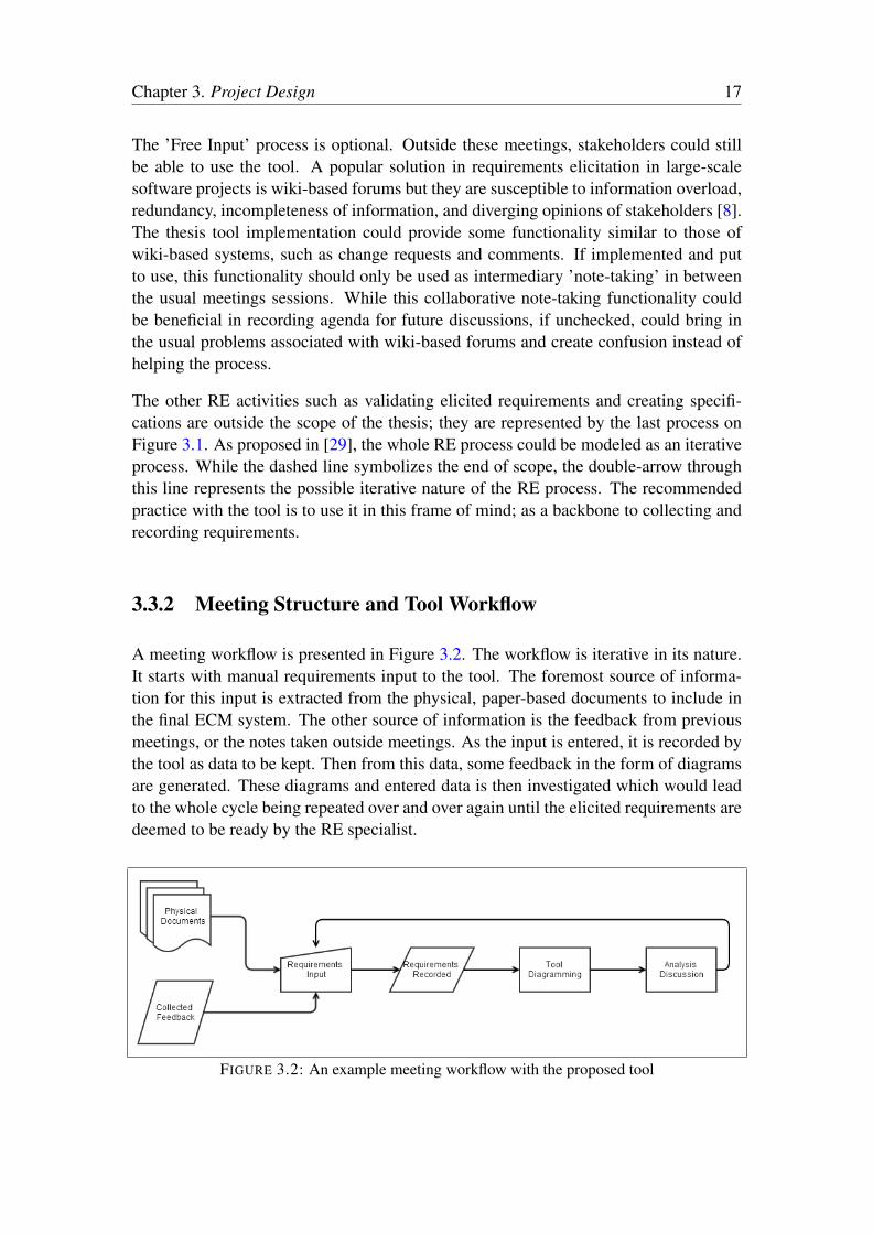
A meeting workflow is presented in Figure 3.2. The workflow is iterative in its nature.It starts with manual requirements input to the tool. The foremost source of informa-tion for this input is extracted from the physical, paper-based documents to include inthe final ECM system. The other source of information is the feedback from previousmeetings, or the notes taken outside meetings. As the input is entered, it is recorded bythe tool as data to be kept. Then from this data, some feedback in the form of diagramsare generated. These diagrams and entered data is then investigated which would leadto the whole cycle being repeated over and over again until the elicited requirements aredeemed to be ready by the RE specialist.
FIGURE 3.2: An example meeting workflow with the proposed tool

Chapter 3. Project Design 18
The thesis tool primarily consists of a web-based solution for capturing requirements.The design of this thesis project focuses on the chosen application domain, that is,document management of ECM systems. As seen in Figure 3.3, the designed GUI willconsist of data grids that are related to each other. First grid will list the documents withtheir names and descriptions. Each physical document will have a corresponding rowon this grid. When a document row is selected on this grid, two related grids will beshown that list ’field requirements’ and ’other requirements’ for the selected document.Field requirements will constitute the actual fields on a documents. For example, if thedocument in question is a passport, some example fields would be passport number,passport holder’s name and surname, date and place of birth, etc. The second grid iswhere other requirements that are not fields will be kept. For example, if the passport isa passport from a country that uses a different alphabet, should the name be recorded inboth alphabets? Or are there any other documents that are needed to be present beforea passport can be issued? These type of requirements that are not explicitly inside thedocument in question should be kept in this second grid. As it can be inferred from themock-up, the idea is to provide a simple GUI.
The entered requirements may have relations among themselves. This idea is inspiredby the Requirements Interchange Format (which will be discussed in detail later on).The idea is creating links between two requirements that defines their relation to eachother. These links could be between requirements of different document or within thesame document. For example, let say we have two documents with issue date fields.If there is a relation between these two dates such as one cannot be after another, thisrelation will be defined as a link. As seen in Figure 3.4, first a requirement of a documentis selected on its grid. When selected, the links associated with the selected requirementwill be shown to the user and on this grid, links will be added, updated, or deleted. Thedescription fields will show which requirement each link is associated with.
In the third mock-up, Figure 3.5, example diagrams are seen. The field and other re-quirements of each document is listed in separate boxes together with the links connect-ing individual requirements. Diagram generation will be tied to a button. Wheneverthe diagram is needed to be investigated, it will be created with the present state ofrequirements.
3.4 Technical Choices
In this section, selected technologies for implementing the thesis tool will be presented.The whole web application architecture is analogous to a Model-View-Controller (MVC)architecture. The Model in this analogy is built on the ReqIF standard while the Viewis implemented with JavaScript through the use of open-source libraries KnockoutJS,JointJS, and jQuery. Lastly, the Controller part consists of Java servlets that handlerequest from the client-side and govern the data model.

Chapter 3. Project Design 19
3.4.1 Model: ReqIF Standard & Eclipse Requirement Modeling
Framework
Requirements Interchange Format (ReqIF) is an OMG standard that is designed to pro-vide a reliable and common way to record requirements [5]. ReqIF was created in2004 by the Hersteller Initiative Software, a body of the German automotive industrythat oversees vendor-independent collaboration [8]. The idea is inspired by the needto communicate requirements between car manufacturers and their suppliers. BeforeReqIF was designed, this exchange was made through common tools such as Wordand Excel and their file formats. ReqIF was created as a file format to replace thesetechnologies to provide a standardized exchange capability.
Even though ReqIF was initially created as a file-based exchange format, inventorsargue it can be more than that [8]. They liken the ReqIF’s relation to requirements withUML’s relation to model-driven software development. After the specification of UML,a lot of publications and work concentrated on this standard, paving the way for low-cost and open-source tools. ReqIF is hoped to encourage a similar development in theare of RE.
ReqIF allows structuring of requirements with many attributes and supports hierarchi-cal structures and links between these requirements as well [8]. Eclipse RMF is anopen-source implementation of the ReqIF standard [6]. In industry, there are a lot ofcustomization of proprietary tools but RMF is built on the open ReqIF standard thatis currently being adopted by commercial tools [8]. The proposed tool will rely on anemerging, solid standard by building on the RMF.
While the underlying data model is safely built on a standard, additional project spe-cific features could be built on top. The proposed tool should incorporate such fea-tures to encourage involvement of the nonengineer stakeholders to the requirementselicitation. What is meant by additional features can simply be a user-friendly GUI,instead of ProR, that creates simple diagrams of requirements with their attributes andlinks, provides traceability of requirements, or makes suggestions between similarly ti-tled requirements etc. This UI could then be used within workshops or individually,and with RE specialist supervision or without it. A medium of solid recording for re-quirements that supports nonengineer stakeholders’ capabilities could be beneficial forbetter requirements elicitation through more freedom in scheduling and greater directcontribution from stakeholders. Of the tacit knowledge class definitions, the third classof requirements would benefit from increased direct involvement by the stakeholderssince they are the ones who withhold this class of information while the RE specialistis unaware of the situation. The fourth class of requirements is where both the RE spe-cialist and other stakeholders are unaware and the tool, with its proposed visualizationand traceability features, could help stimulate further investigation by both parties.

Chapter 3. Project Design 20
3.4.1.1 Eclipse Requirement Modeling Framework GUI: ProR
The Eclipse RMF has an Eclipse plugin called ProR [8]. This plugin constitutes aGUI inside Eclipse for creating and modifying ReqIF specifications. Since ProR is anEclipse plugin, the possibility of usage by nonengineer stakeholders is limited. It is notdesigned with a nonengineering audience in mind. So, the solution proposed within thisthis thesis is to develop a new tool that uses RMF data models for ReqIF but independentof ProR; has its own GUI and is online which opens it to many extra features such asremote access, collaboration, and diagram creation.
The collaboration mentioned here is an in-place collaboration such as a forum collabo-ration. Of course, when using ProR to create ReqIF specifications, these specificationfiles are ultimately created to be shared between different organizations (e.g. automo-bile brand factories and automobile-part factories). However, with the designed toolcollaboration as the file is being specified is more important rather than sharing a fin-ished specification with another organization.
A relevant advantage of ProR over the proposed tool is that it works directly on theimplemented ReqIF classes. This is advantageous because the implementation of aspecialized GUI would need to have its own corresponding data model to bind withReqIF data model. For example, the designed web-based tool will need to convertthese data types or adapt new data types for web-specific use (e.g. JavaScript classes).This will produce much overhead for the tool if it is to implement correspondence withthe whole standard. Although this is a definite drawback for the designed tool, it isarguable that the benefits brought in by the tool as such could overweigh the extra workassociated with its data model communication.
3.4.2 Client-side: AJAX, JSON, and JavaScript
AJAX stands for Asynchronous JavaScript and XML. It is a collection of techniquesused to create asynchronous web applications. Asynchronous web applications dependon partial updates of pages instead of full page updates with HTML data received fromthe server.
Before the popularization of asynchronous web applications, every HTTP request re-sulting from a user action loaded a complete HTML page from the server. This resultedin poor user experience as each action made the web page disappear and reappear onthe client-side. The term AJAX represents a group of Web technologies that are usedto implement a Web application that communicates with a server in the background,without interfering with the current state of the page. In the article that coined the termAJAX [30], it is explained that the following technologies are incorporated:
• HTML (or XHTML) and CSS for presentation

Chapter 3. Project Design 21
• The Document Object Model (DOM) for dynamic display of and interaction withdata
• XML for the interchange of data, and XSLT for its manipulation
• The XMLHttpRequest object for asynchronous communication
• JavaScript to bring these technologies together
However, the technologies that are mentioned in this article have advanced since thepublication of this article in 2005. Now XML and XSLT is not required. In this thesisimplementation, JavaScript Object Notation (JSON) will be used for data exchange be-tween server and client-sides. JSON is a lightweight, text-based, language independentdata interchange format[31]. It is chosen to be used as the data interchange format inthis thesis project.
jQuery is a popular general purpose JavaScript library that is used by other JavaScript li-braries as well. By using jQuery, asynchronous HTTP requests will be made with JSONpayload. The data received from the server-side will be kept in JavaScript classes withKnockoutJS bindings. KnockoutJS is a JavaScript library that focuses on tying HTMLelement with JavaScript models. It achieves a clean implementation of data model andUI communication on the client-side. It also has JSON encoding/decoding capabilitieswhich will be used. Lastly, JointJS will be used to dynamically create diagrams onHTML5 canvas element. It is open-source and some custom diagram elements will beextended from some base classes in JointJS.
3.4.3 Server-side: Java Servlets & Jackson
A ”servlet” is a Java class that responds to requests through HTTP or other protocols.In this project, some Java servlets will be deployed on an Apache Tomcat server. Theywill listen client requests across HTTP. They will perform operations on the data modelwhile providing information to the client-side.
In the previous section, it is described that JSON will be used as the data interchangeformat. On the client-side, KnockoutJS and native JavaScript parsers are used for han-dling JSON. On the server-side, this task is performed by the Java library, Jackson.It is an open-source JSON processor. The serialized JSON strings will be exchangedthrough the content payload of HTTP requests and responses between the server andclient-side. For example, a new document that is created on the client-side will be se-rialized by JavaScript classes, sent with an AJAX request over to the server-side. Thisdocument will then be deserialized into a Java object and stored by the server with anassigned ID. Then, this newly assigned ID will be written on the response message ofthe server to the client.

Chapter 3. Project Design 22
FIGURE 3.3: GUI grids mock-up

Chapter 3. Project Design 23
FIGURE 3.4: Requirement links mock-up

Chapter 3. Project Design 24
FIGURE 3.5: Diagram mock-up
Chapter 4
Project Implementation
In this chapter, the implementation of the thesis tool is presented. First, the the overallstructure of the tool will be explained. Then each part will be explained in more detail.Finally, the difficulties encountered during the implementation will be presented.
4.1 Overall Architecture
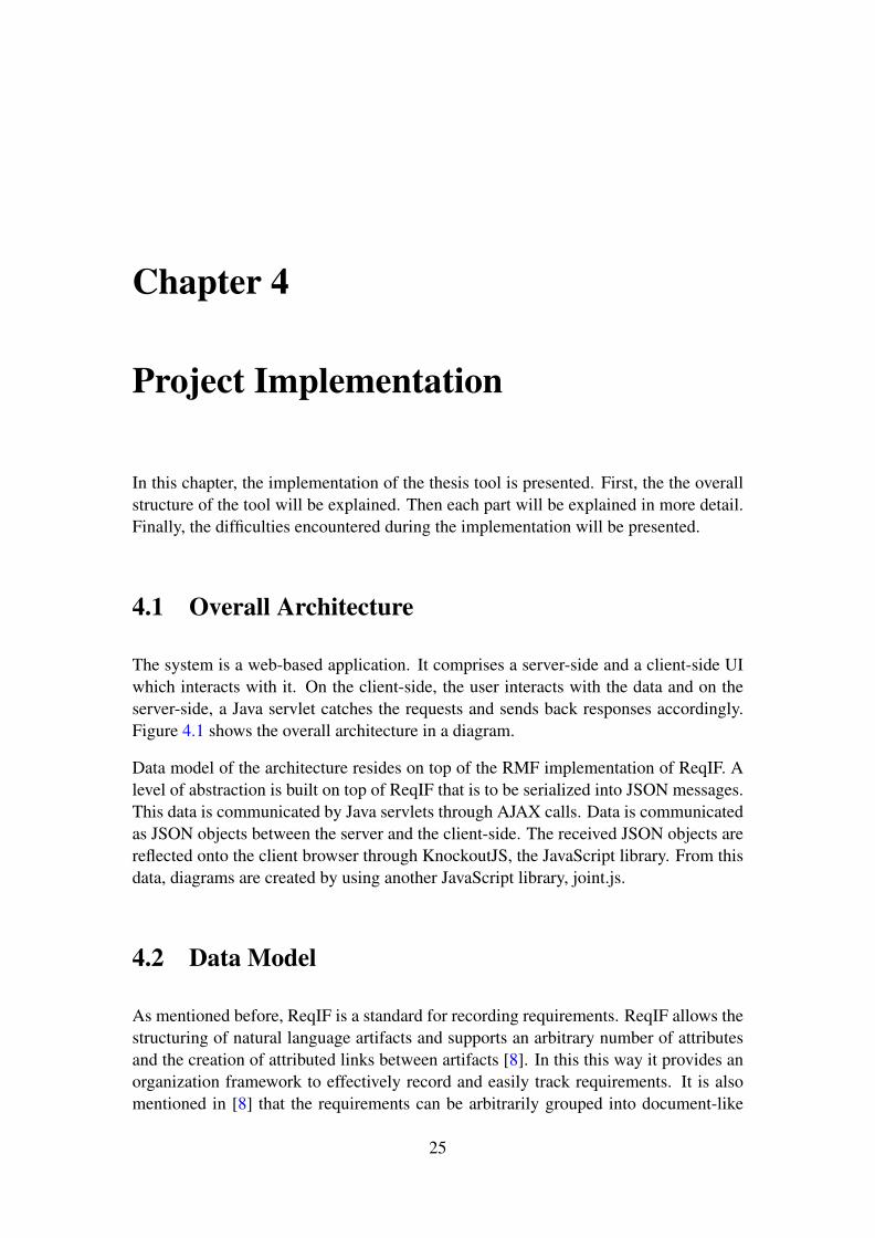
The system is a web-based application. It comprises a server-side and a client-side UIwhich interacts with it. On the client-side, the user interacts with the data and on theserver-side, a Java servlet catches the requests and sends back responses accordingly.Figure 4.1 shows the overall architecture in a diagram.
Data model of the architecture resides on top of the RMF implementation of ReqIF. Alevel of abstraction is built on top of ReqIF that is to be serialized into JSON messages.This data is communicated by Java servlets through AJAX calls. Data is communicatedas JSON objects between the server and the client-side. The received JSON objects arereflected onto the client browser through KnockoutJS, the JavaScript library. From thisdata, diagrams are created by using another JavaScript library, joint.js.
4.2 Data Model
As mentioned before, ReqIF is a standard for recording requirements. ReqIF allows thestructuring of natural language artifacts and supports an arbitrary number of attributesand the creation of attributed links between artifacts [8]. In this this way it provides anorganization framework to effectively record and easily track requirements. It is alsomentioned in [8] that the requirements can be arbitrarily grouped into document-like
25

Chapter 4. Project Implementation 26
FIGURE 4.1: Overall architecture
constructs which is what the tool is designed to do. Data model of the thesis tool isbuilt on top of RMF implementation of ReqIF; that is, wrapper classes for some ReqIFclasses are implemented. The wrapper classes are namely ReqIFRoot, DocumentReqIF,SpecObjectReqIF, and SpecRelationReqIF.
Figure 4.2 shows a UML class diagram of the whole data model architecture. TheReqIF implementation of RMF is denoted by the package RMF ReqIF. These classesare referenced by the four wrapper classes. The class DocumentRepository functionsas the database for the web-application. This class is used by the server-side classes(Servlets) to store and retrieve data.
Before going into the wrapper classes, the ReqIF classes that are used and/or referencedwill be explained. ReqIF constitutes an XML structure. At the top of the XML tree, isthe element called ReqIF. It is simple a placeholder for the whole requirements docu-ment. The important field of this class is ReqIFContent which holds all the followingrequirements data inside itself. In the ReqIF specification, a SpecObject represents arequirement. A SpecObject can have a SpecType which is used as a type indicator. ASpecification holds SpecHierarchy elements which refers to one SpecObject each. Inthis way, SpecObjects are grouped and organized. Using referencing of SpecHierarchyelements, the same SpecObject can be referenced from various SpecHierarchies andalso from various Specifications. A SpecRelation represents a relation between twoSpecObjects; a source and a target.

Chapter 4. Project Implementation 27
Specification, SpecObject, and SpecRelation can have associated type objects in ReqIF;SpecificationType, SpecObjectType, and SpecRelationType respectively. These typeobjects of ReqIF are used to create a template of fields for their respective objects. Forexample, a SpecObject has a number of AttributeValues, which hold the actual contentof the SpecObject. A SpecObjectType also has a list of Attributes which gives theseAttributes to a SpecObject when it is set as the type of that SpecObject. For simplicity,and because of lack of need for the design at hand, these Attributes of SpecObjectsare not used. Instead, only the definition fields are used as requirements descriptions.Similarly, type objects are not used as templates for Attributes but rather as a simpletype indicator string.
These mentioned ReqIF classes are used in specific parts of the data model necessaryto collect requirements for the selected project domain, ECM document management.The documents are organized separately with their field and other requirements. Thecorresponding ReqIF class for these documents are Specifications. This allows for adocument specification to reference requirements which are backed by SpecObjectsthemselves. The relations between requirements are represented by SpecRelation ob-jects. To summarize;
1. ReqIF element sits on top of the whole requirements specification.
2. Specification groups the SpecObject requirements into documents that correspondto physical documents that the ECM system is designed to contain.
3. SpecObject represents an actual requirement (field or other). Its description fieldis used for storing natural language requirements data.
4. A SpecRelation is used to link together two requirements. It also has its owndescription.
In addition to these, SpecHierarchy objects are used with the Specifications but sincethey are not needed to be communicated outside the server-side, they do not have acorresponding wrapper class. There are two SpecType objects that are used to denoteif a SpecObject is a field requirement or an other requirement. Also, a single Spec-ificationType object is used for all documents. It denotes that the Specifications are’document’s. For the same reason as the SpecHierarchy class, these classes do not havewrapper classes either.
The corresponding wrapper classes for the enumerated ReqIF classes are:
1. RootReqIF
2. DocumentReqIF
3. SpecObjectReqIF

Chapter 4. Project Implementation 28
4. SpecRelationReqIF
These wrapper classes are implemented to provide a level of abstraction that hides thedetails of ReqIF implementation while making JSON serialization possible. This willbe discussed in detail later on.
DocumentRepository serves as the database of the application. It is obviously not meantto be included in a production version of the tool as it provides static data that is ini-tialized on each server reset. It is meant to be useful only in the proof-of-concept thatis presented with this thesis. Functions getNewDefaultDocument and getSomeSpecRe-lations, together with a piece of static code, populate initial data into the ReqIF datamodel that is represented by attribute root of type RootReqIF.
According to ReqIF specification, ReqIF objects should be provided with unique IDs.Next three functions getUniqueDocID, getUniqueSpecID, and getUniqueRelationIDprovide unique IDs for ReqIF objects. The ID creation does not necessarily need to beimplemented inside the database; these function are inside DocumentRepository classonly because it is convenient and their placement is not crucial. Next three groups offunctions correspond to creating, updating, and deleting documents, requirements, andrelations. Finally, it provides a getter function for the ReqIFRoot object. These func-tions are called from the servlets with the exception of getSpecObject function which iscalled from the SpecRelationReqIF class to find SpecObjects by their IDs.
RootReqIF class represents the whole of a requirements specification. It holds the top-level ReqIF element together with a list of DocumentReqIF and SpecRelationReqIFobjects. getHeaderTitle and setHeaderTitle functions operate on ReqIFHeader attributeof the ReqIF element which is expected to contain the name of the specification (e.g.general project name). There are functions that work with the corresponding functionsin DocumentRepository to create, update, and delete elements. There are getter func-tions for documents and relations.
DocumentReqIF class encapsulates requirements for a document that is to be includedin the ECM system. It defines a static document type (SpecificationType) that is cur-rently the same for all documents since there is no distinction implemented betweendocuments. Another two static types (SpecObjectType) are defined for requirementsthat the document holds. These are set as types of individual requirements. The docu-ment object is of Specification class and it is held by the field document. There are twolists, fieldRequirements and otherRequirements, that hold the field and other require-ments respectively. There are functions for inserting, updating and removing require-ments and finally getter functions for requirement lists and the document itself.
SpecObjectReqIF class wraps a single requirement. The SpecObjects are stored underdocuments and sometimes it is needed to reach their DocumentReqIF parents. So, IDsfor their parent documents are held in SpecObjectReqIF in the attribute docId. The typeof SpecObject is set to one of the two static SpecObjectTypes defined in DocumentRe-qIF, namely, fieldType and otherType.

Chapter 4. Project Implementation 29
SpecRelationReqIF class wraps a SpecRelation which defines a relation between tworequirements. The source and target SpecObjectReqIF objects are held by this class.However, getter/setter functions for the source and target return/take string IDs. This isdone to relive JSON from serializing these SpecObjectReqIF objects twice since theyare already being communicated once with the client through DocumentReqIF objects.
It should be noted here that the wrapper classes hold relevant objects under hierarchiesboth in their ReqIF references and in their own lists. For example, in ReqIFRoot class,DocumentReqIF objects that are inserted are kept in the list docs of RootReqIF whilethe Specification objects that these DocumentReqIF objects hold are added to the rootReqIF object as well. The same goes for the requirements kept in DocumentReqIF ob-jects; they are stored in both the Specification object (as SpecObjects) and in seperatelists inside DocumentReqIF (as SpecObjectReqIF). This is done to allow JSON to per-form more efficiently by reducing the size of the serialized JSON string output. Thiswill be mentioned in more detail in the next section.
4.3 Server-side Implementation
The server-side implementation comprises the Java servlets that respond to client re-quests, response objects, and a JSON encoder/decoder. These classes can be seen inFigure 4.3.
There are four servlet classes implemented that extend HttpServlet class of Java: ReqIF-Servlet, DocumentServlet, SpecObjectServlet, and SpecRelationServlet. These servletsshare the workload associated with calls regarding each of the four wrapper classesdescribed in the previous section. They work with the backend data model which isrepresented by the package Backend in Figure 4.3.
RequestContext class wraps request handling functionality in itself. A RequestCon-text is created for each call that reaches a servlet. It takes a HttpServletRequest anda HttpServletResponse objects as references to its constructor and saves references tothese objects in its attributes request and response respectively. References for the In-putStream of request and the OutputStream of response is created. A Map is used forkeeping parameters passed with a request. The function getRequestContentAs is usedto read objects from the AJAX content of the requests while the function writeToRe-sponseJson writes response objects to the response stream. These two functions worktogether with the class JsonEncoder so they are generically typed as well.
JsonEncoder class uses the JSON processor library included in the project, Jackson[32]. It is a simple generic class that encodes/decodes objects into/from JSON strings.In its constructor, it takes the type of objects that are going to be used with it. It usesthe ObjectMapper class from Jackson library to perform these two operations on thefour wrapper classes previously described. When the ObjectMapper is provided withan object to serialize (i.e. turn into a JSON string), it gathers the attributes through
Chapter 4. Project Implementation 30
the getter functions of the object being serialized. The same goes for deserialization(i.e. create Java objects from JSON string) through the use of setter functions. Thegetter/setter functions in wrapper classes are set such that the size of JSON strings areminimalized.
Response class defines an object for communicating response information back to theclient after a request. It has a message and a boolean to denote whether the request hasbeen successfully carried or not. There are two special classes that extend Responseclass: GetRootResponse and SaveResponse. GetRootResponse is used when the clientfirst opens the web page. It is used to send the RootReqIF object over to the client-side.After this initiation, no complete object data is sent to the client. However, there are twospecial cases when creating and updating new objects. When creating a new object, allthe information is provided by the client-side except the ID. The ID is uniquely assignedby the DocumentRespository. This ID is needed to be sent back to the client so it canbe stored and displayed on the client-side. SaveResponse class is used for this purpose.The ID of the newly created object is stored in a SaveResponse object and it is sent afterserialized by JsonEncoder class. The saveType is also set to INSERT. The second casewhere SaveResponse is needed is when an update is being requested. In this case theattribute saveType is used to mark whether any information has been updated or not (i.e.UPDATED or NONE.
4.4 Client-side Implementation
Client-side implementation consists of a single web page governed by some JavaScriptclasses that use third-party JavaScript libraries. The used libraries are KnockoutJS [33],JointJS [34], and jQuery [35]. Figure 4.4 shows a UML class diagram of the client-sideclass structure.
As mentioned in the previous chapter, KnockoutJS, allows for easy binding of JavaScriptobjects with HTML Document Object Model (DOM) objects. It has a Model-View-View Model (MVVM) architecture. MVVM is similar to MVC but is designed specif-ically for UIs. Model and View in MVVM corresponds to the domain model and GUIas in the classic MVC architecture. The difference of MVVM lies on the idea of ViewModel. This layer of the architecture is a mediator between the domain data and theirrepresentation on the View. It provides data binding between View Model and View. Ina way, it is a specialized Controller.
In Listing 4.1, an example usage of KnockoutJS is presented with a piece of simplifiedcode from the implementation. The function Document implements a simple JavaScriptclass that holds two attributes; id and description. It can also be instantiated with ex-isting document info. ViewModel is the View Model implementation which holds theobjects to be bound to the View and relevant functions. In this case, it holds a sin-gle Document objects and defines a function that makes an AJAX request to a Javaservlet. On the last three lines of the script element, a ViewModel object is created,

Chapter 4. Project Implementation 31
supplied to KnockoutJS to apply bindings for, and an AJAX call is made with jQueryto request the document from the server-side. KnockoutJS introduces an HTML at-tribute data-bind. Using this attribute, View Model objects are bound with the HTMLelements of the View. The <div> element is bound with document while the textof a span element and the text of an input element is bound with id and description ofdocument respectively. From this point on, if the description is modified through theinput, the attribute of the Document object will be automatically updated. The oppo-site also holds true; if the description attribute is changed, for example, by activitiesof another function, the input element on the HTML will be updated as well. Thisis achieved through KnockoutJS’s observable JavaScript objects that detect changesand notify their observers. The line that creates the document object is defined asko.observable(new Document()) initiates it as a KnockoutJS observable.<script>
function Document(document) {
this.id = ’’;
this.description = ’’;
if (document) {
this.id = document.id;
this.description = document.description;
}
};
var ViewModel = function() {
var self = this;
self.document = ko.observable(new Document()); // An observable variable
self.getDocument = function() {
$.ajax({
url : ’Servlet’,
type : ’GET’,
success : function(responseData, textStatusStr, jqXHR) {
if (responseData.successful) {
self.document(responseData.document);
} else {
alert(’Unsuccessful: ’ + responseData.message);
}
},
error : function(jqXHR, textStatusStr, errorStr) {
alert(errorStr + ’ error at getDocument’);
}
});
};
};
var viewModel = new ViewModel();
ko.applyBindings(viewModel); // This starts Knockout bindings
viewModel.getDocument();
</script>

Chapter 4. Project Implementation 32
<html>
[...]
<body>
<div data-bind="with: document">
<p>Document ID: <span data-bind="text: id" /></p>
<p>Description: <input type="text" placeholder="Enter description..." data-bind="
value: description"></p>
</div>
[...]
</body>
</html>
LISTING 4.1: KnockoutJS example
Listing 4.1 presents a simple example of how KnockoutJS is used together AJAX toconstruct the client-side structure. A UML diagram for the actual client-side implemen-tation of the tool is presented in Figure 4.4 and it basically consists of a complicatedversion of the presented example in action.
Figure 4.5 shows a screenshot of the implemented tool. It consists of a table for de-fined documents. When a row of this grid is selected, the field and other requirementsassociated with that particular document is listed on two separate grids underneath thefirst one. When a row of one of the requirement grids is selected, a table that lists therelations concerning that requirement is listed on a grid that appears below that row.Under each grid, there is a button for adding a new row (i.e. creating a new object) anda save button that will create an AJAX call to the server to save the current state of thegrid. Also, on each row there is a delete button while the fields of objects are modifiablein place.
RootModel is the View Model that holds objects that are displayed and modified throughthe HTML page. It holds instances of Root, Document, SpecObject, and SpecRelationclasses while the HTML elements is bound to this data. RootModel holds rootObjobject, documents array, and relations array as KnockoutJS observables. Italso holds observable objects selectedDocument and selectedSpecObjectto keep track of selected rows of respective grids. showedRelations object is an-other observable array that is used to calculate and store relations related to a SpecOb-ject when its corresponding row is selected on its grid.
setRoot function sets the values of rootObj, documents, and relations afterreceiving a response for the AJAX call made through the function getRoot. Func-tions starting with ”add” are called when the ”Add ...” buttons below grids are clicked.They add a new object into their respective arrays; one of documents, relations,or one of requirement arrays in Document class. The two functions starting with ”se-lect” are called when a document or requirement row is selected on the grids. Theyset the selectedDocument and selectedSpecObject so they can be bound toappearing requirements and relations grids. getDocumentByID is a utility function
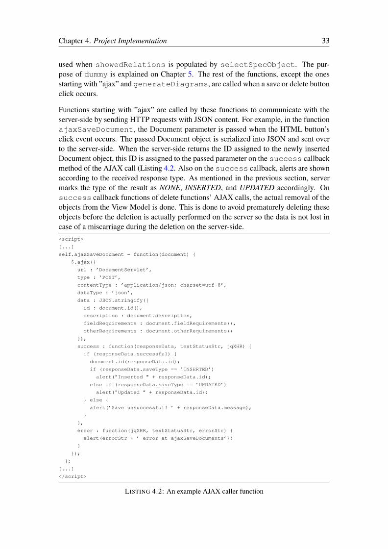
Chapter 4. Project Implementation 33
used when showedRelations is populated by selectSpecObject. The pur-pose of dummy is explained on Chapter 5. The rest of the functions, except the onesstarting with ”ajax” and generateDiagrams, are called when a save or delete buttonclick occurs.
Functions starting with ”ajax” are called by these functions to communicate with theserver-side by sending HTTP requests with JSON content. For example, in the functionajaxSaveDocument, the Document parameter is passed when the HTML button’sclick event occurs. The passed Document object is serialized into JSON and sent overto the server-side. When the server-side returns the ID assigned to the newly insertedDocument object, this ID is assigned to the passed parameter on the success callbackmethod of the AJAX call (Listing 4.2. Also on the success callback, alerts are shownaccording to the received response type. As mentioned in the previous section, servermarks the type of the result as NONE, INSERTED, and UPDATED accordingly. Onsuccess callback functions of delete functions’ AJAX calls, the actual removal of theobjects from the View Model is done. This is done to avoid prematurely deleting theseobjects before the deletion is actually performed on the server so the data is not lost incase of a miscarriage during the deletion on the server-side.<script>
[...]
self.ajaxSaveDocument = function(document) {
$.ajax({
url : ’DocumentServlet’,
type : ’POST’,
contentType : ’application/json; charset=utf-8’,
dataType : ’json’,
data : JSON.stringify({
id : document.id(),
description : document.description,
fieldRequirements : document.fieldRequirements(),
otherRequirements : document.otherRequirements()
}),
success : function(responseData, textStatusStr, jqXHR) {
if (responseData.successful) {
document.id(responseData.id);
if (responseData.saveType == ’INSERTED’)
alert("Inserted " + responseData.id);
else if (responseData.saveType == ’UPDATED’)
alert("Updated " + responseData.id);
} else {
alert(’Save unsuccessful! ’ + responseData.message);
}
},
error : function(jqXHR, textStatusStr, errorStr) {
alert(errorStr + ’ error at ajaxSaveDocuments’);
}
});
};
[...]
</script>
LISTING 4.2: An example AJAX caller function
Chapter 4. Project Implementation 34
The four classes, Root, Document, SpeObject, and SpecRelation classes hold the cru-cial information. Document class’s attribute id is an observable object. When a newDocument object is being created, it does not have an ID. Documents are assigned IDswhen they are saved by the server. The assigned IDs are sent back from the serveron responses and written on id attributes. Since id attribute is an observable, theView is updated to show IDs when they are received and written on ids. The observ-able arrays fieldRequirements and otherRequirements hold requirementsas SpecObject objects while allRequirements hold the composition of these twoarrays. allRequirements is a special kind of observable, a computed observable,which means it is computed from other observable objects. SpecObject and SpecRela-tion holds requirements and relations respectively.
All these four classes, they are parallel to their counterparts in the server-side, that is,the four wrapper classes. However, they have some extra, client-side specific attributes.allRequirements attribute of the Document class was one of them. SpecRelation’slinkedDoc, linkedFrom, and linkedTo are others. A relation links two require-ments together; source and target. So when listing relations on the grid of theView, they are listed under both these requirements. According to the selected require-ment row, source or target, the ”Linked Document” and ”Linked Requirement” fieldsshow the information of the other requirement. linkedDoc and linkedTo keeps thisother requirement’s information while linkedFrom hold the selected requirement.
The last function on the RootModel class is generateDiagram. This function iscalled on the ”Diagram” button’s click event. generateDiagram creates JointJSobjects from the information present in the View Model. JointJS is a diagramminglibrary that uses the canvas element of HTML5. It has defined diagram element classesthat are base classes like rectangles or links or special purpose classes to be used forcreating specific types of diagrams such as ER diagrams, UML class diagrams, logiccircuits, etc. In this implementation, three classes are extended from base classes ofJointJS: reqif.Document and reqif.Requirement. The purposes of these classes should beobvious. JointJS’s default class for links, joint.dia.Link, is used to display relations. IDsof relations are put on the links but since the descriptions would obstruct the diagramgreatly, reqif.RelationLegend class is designed to create a legend of descriptions. Anexample diagram is shown in Figure 4.6. The documents are draggable. Also, the shapeof the links are adjustable so they can be reshaped to look better.
4.5 Technical Issues Encountered
4.5.1 Data Model: ReqIF & View
As mentioned before, ProR implementation resides directly on top of the ReqIF imple-mentation of RMF and it is advantageous because of the lack of need for intermediateclass structures: the wrapper classes of the server and the JavaScript classes that hold
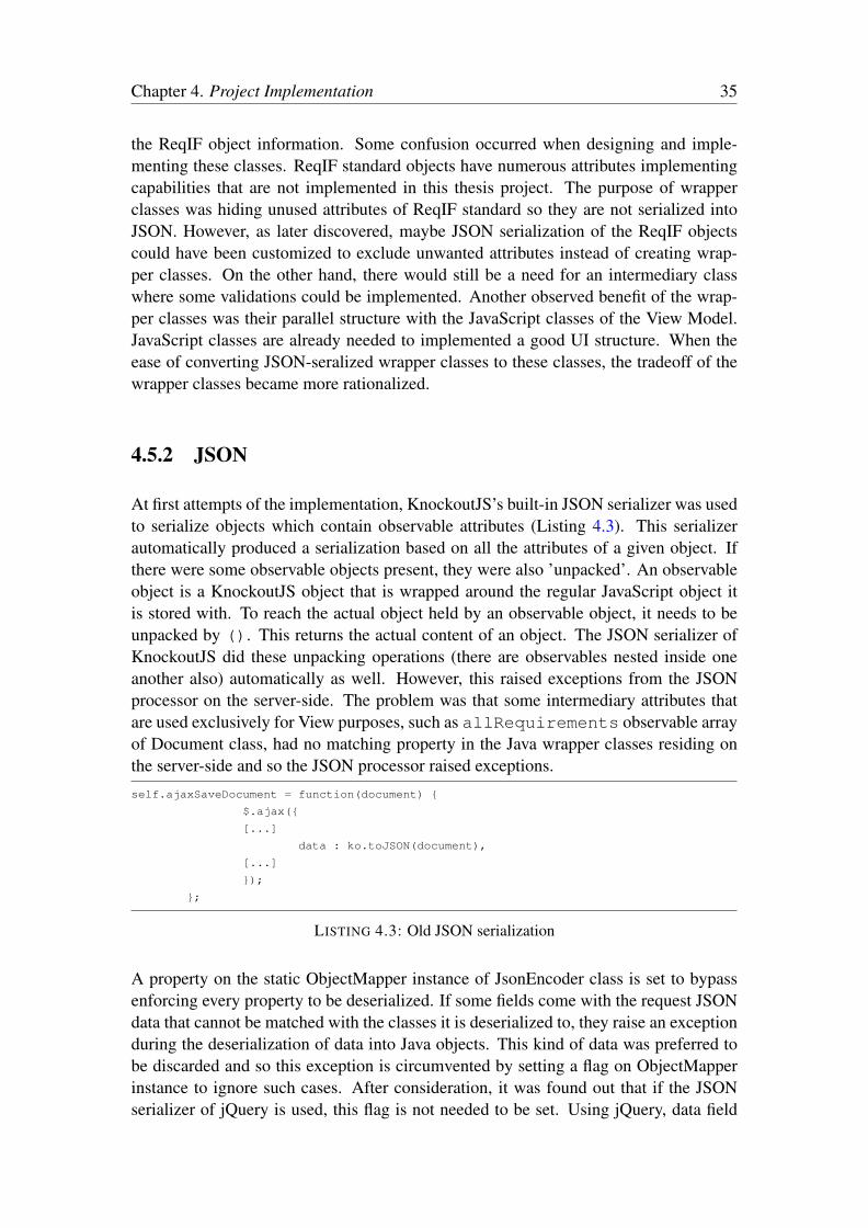
Chapter 4. Project Implementation 35
the ReqIF object information. Some confusion occurred when designing and imple-menting these classes. ReqIF standard objects have numerous attributes implementingcapabilities that are not implemented in this thesis project. The purpose of wrapperclasses was hiding unused attributes of ReqIF standard so they are not serialized intoJSON. However, as later discovered, maybe JSON serialization of the ReqIF objectscould have been customized to exclude unwanted attributes instead of creating wrap-per classes. On the other hand, there would still be a need for an intermediary classwhere some validations could be implemented. Another observed benefit of the wrap-per classes was their parallel structure with the JavaScript classes of the View Model.JavaScript classes are already needed to implemented a good UI structure. When theease of converting JSON-seralized wrapper classes to these classes, the tradeoff of thewrapper classes became more rationalized.
4.5.2 JSON
At first attempts of the implementation, KnockoutJS’s built-in JSON serializer was usedto serialize objects which contain observable attributes (Listing 4.3). This serializerautomatically produced a serialization based on all the attributes of a given object. Ifthere were some observable objects present, they were also ’unpacked’. An observableobject is a KnockoutJS object that is wrapped around the regular JavaScript object itis stored with. To reach the actual object held by an observable object, it needs to beunpacked by (). This returns the actual content of an object. The JSON serializer ofKnockoutJS did these unpacking operations (there are observables nested inside oneanother also) automatically as well. However, this raised exceptions from the JSONprocessor on the server-side. The problem was that some intermediary attributes thatare used exclusively for View purposes, such as allRequirements observable arrayof Document class, had no matching property in the Java wrapper classes residing onthe server-side and so the JSON processor raised exceptions.self.ajaxSaveDocument = function(document) {
$.ajax({
[...]
data : ko.toJSON(document),
[...]
});
};
LISTING 4.3: Old JSON serialization
A property on the static ObjectMapper instance of JsonEncoder class is set to bypassenforcing every property to be deserialized. If some fields come with the request JSONdata that cannot be matched with the classes it is deserialized to, they raise an exceptionduring the deserialization of data into Java objects. This kind of data was preferred tobe discarded and so this exception is circumvented by setting a flag on ObjectMapperinstance to ignore such cases. After consideration, it was found out that if the JSONserializer of jQuery is used, this flag is not needed to be set. Using jQuery, data field

Chapter 4. Project Implementation 36
of the AJAX call is set with attributes of the Document object omitting the problem-atic allRequirements array (Listing 4.4). The same problem was present for thelinkedDoc, linkedFrom, and linkedTo attributes of the SpecRelation class aswell.self.ajaxSaveDocument = function(document) {
$.ajax({
[...]
data : JSON.stringify({
id : document.id(),
description : document.description,
fieldRequirements : document.fieldRequirements(),
otherRequirements : document.otherRequirements()
}),
[...]
});
};
LISTING 4.4: Fixed JSON serialization
4.5.3 Customizing JointJS
JointJS has many different ready-to-use sublibraries for specific purposes. However,creating custom classes proved to be not so easy. There is an API entry on JointJS web-site [34] but it does not really constitute an API documentation but rather a guideline.Lack of adequate API and also lack of commented code, it became very hard to modifydefault behavior of classes. For example, join.dia.Link class comes with functionality,through the canvas, such as deleting the link or changing its source and target connec-tions to different elements. These features were to be removed from this implementationas the other parts do not support it. Since the code is not easily reusable, the way to donecessary modifications was to modify CSS. The difficulties of JointJS suggests that itis worth considering another diagramming library in future.

Chapter 4. Project Implementation 37
FIGURE 4.2: UML class diagram for the data model

Chapter 4. Project Implementation 38
FIGURE 4.3: UML class diagram for the server-side implementation

Chapter 4. Project Implementation 39
FIGURE 4.4: UML class diagram for the client-side implementation
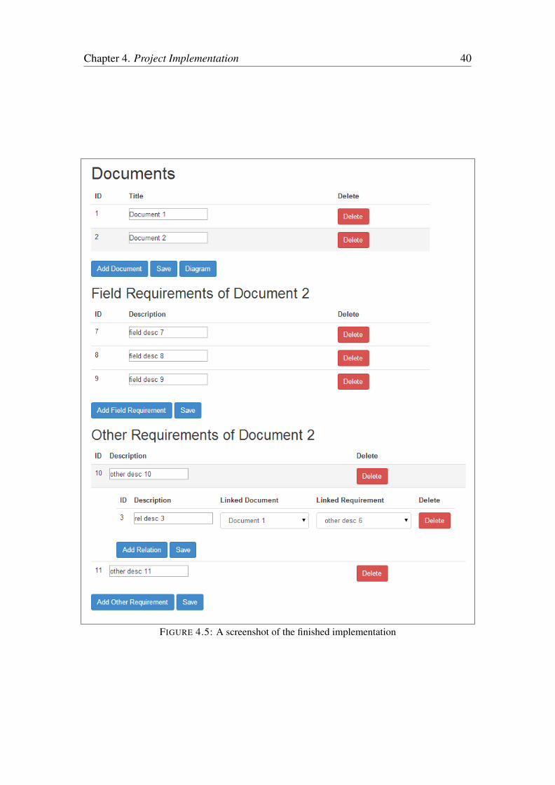
Chapter 4. Project Implementation 40
FIGURE 4.5: A screenshot of the finished implementation

Chapter 4. Project Implementation 41
FIGURE 4.6: A screenshot of a generated diagram

Chapter 5
Tests
5.1 Test Design
The UI of the implementation was tested. First, a risk analysis is done to list possiblerisks with the UI. Then, test suites to test for these lists are established. Lastly, specifictest cases and scenarios are designed.
5.1.1 Identifying Risks
After consideration, four classes risk are defined: functional risks, usability risks, ef-ficiency risks, and portability risks. Functional risks include suitability and accuracy.Suitability covers the functionality of the interface on the level of functioning and dis-playing correctly. Accuracy risks include accepting incorrect data or creating incorrectoutput (i.e. diagram, grids). The next class of risks, usability, lists understandability,learnability, and attractiveness as sub-risks. Understandability risk is concerned withthe users’ inability to understand the purose of the interface. Learnability is concernedwith inability to learn how to use the interface and attractiveness risk is that the interfaceis not visually appealing to the users. The third class of risk class is efficiency with asingle sub-risk; time behavior. It is the risk that the response time of the interface mightbe too long and obstruct the flow of usage. Last class of risks, portability, is concernedwith the adaptability of the interface across different platforms (i.e. browsers). Theserisk classes are listed in Table 5.1.
In Table 5.1, at the columns ”Technology Risk” and ”Business Risk”, the risk potentialvalues are assigned between 1 (highest) and 5 (lowest). ”Risk Priority” values are themultiplications of these two columns to reach a final indicator of priority. It’s rangevalues are listed in Table 5.2. These values are used in deciding what test suites will bedesigned and also the extent of actual testing that will be done to cover defined risks.
42
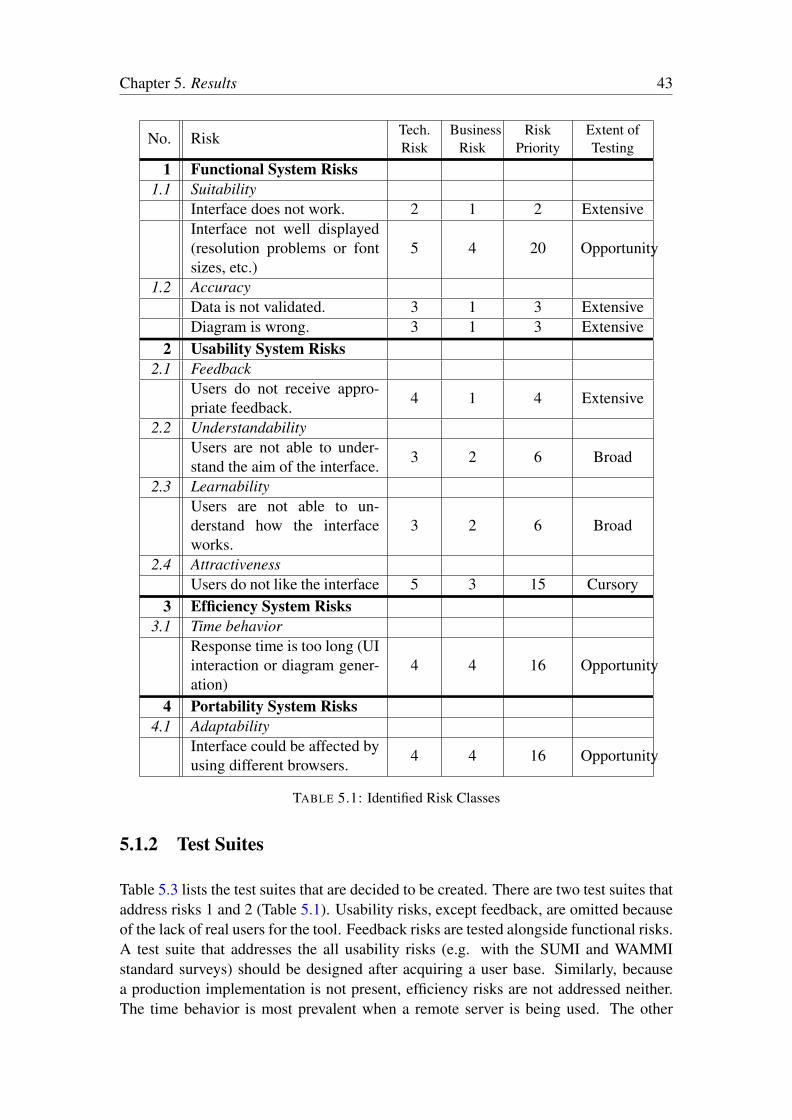
Chapter 5. Results 43
No. Risk Tech.Risk
BusinessRisk
RiskPriority
Extent ofTesting
1 Functional System Risks
1.1 SuitabilityInterface does not work. 2 1 2 ExtensiveInterface not well displayed(resolution problems or fontsizes, etc.)
5 4 20 Opportunity
1.2 AccuracyData is not validated. 3 1 3 ExtensiveDiagram is wrong. 3 1 3 Extensive
2 Usability System Risks
2.1 FeedbackUsers do not receive appro-priate feedback. 4 1 4 Extensive
2.2 UnderstandabilityUsers are not able to under-stand the aim of the interface. 3 2 6 Broad
2.3 LearnabilityUsers are not able to un-derstand how the interfaceworks.
3 2 6 Broad
2.4 AttractivenessUsers do not like the interface 5 3 15 Cursory
3 Efficiency System Risks
3.1 Time behaviorResponse time is too long (UIinteraction or diagram gener-ation)
4 4 16 Opportunity
4 Portability System Risks
4.1 AdaptabilityInterface could be affected byusing different browsers. 4 4 16 Opportunity
TABLE 5.1: Identified Risk Classes
5.1.2 Test Suites
Table 5.3 lists the test suites that are decided to be created. There are two test suites thataddress risks 1 and 2 (Table 5.1). Usability risks, except feedback, are omitted becauseof the lack of real users for the tool. Feedback risks are tested alongside functional risks.A test suite that addresses the all usability risks (e.g. with the SUMI and WAMMIstandard surveys) should be designed after acquiring a user base. Similarly, becausea production implementation is not present, efficiency risks are not addressed neither.The time behavior is most prevalent when a remote server is being used. The other

Chapter 5. Results 44
1 - 5 Extensive6 - 10 Broad11 - 15 Cursory16 - 20 Opportunity21 - 25 Report Bugs
TABLE 5.2: Risk Priority Ranges
Test Suite Test Objectives
Risk
Cover-
age
Sequence
Group
Interface Functionality Verify all the functionalities of theinterface. Find bugs in the inter-face logic. Ensure that there areno problems during the execution inthe browser.
1 1
Portability Verify the adaptability of the inter-face
4 3
TABLE 5.3: Designed Test Suites
operations are done on the client-side with JavaScript so they are instantaneous. Also,the server communication is done with asynchronous calls so no obstructions due tolatency is expected.
5.1.3 Test Cases and Scenarios
As explained in Chapter 4, the interface consists of four grids/forms:
• Document Form
• Field Requirement Form
• Other Requirement Form
• Relation Form
Tables 5.4, 5.5, 5.6 and 5.7 show test cases to apply on individual forms to test them.The listed tests are similar across all four forms. There is a click-row operation to betested on all forms (except Relation Form) that should select a row and list its childrenobjects. The operations addition, updating, and deletion are tested on all forms. Thereis also a pre-condition of number of grid-rows. Without any rows present, some outputsare changed and, since ”Delete” buttons are located on each row, deletion is disabled.

Chapter 5. Results 45
Case
No.Input
Pre-condition #of documents Expected Output
1 Click on a document row >0 The related requirementsare displayed
2 Button ”Add Document” >0 Add a new empty doc-ument row with ID as-signed
3 Button ”Save” >0 Updates are performed (ifthere are any) and feed-back is given
4 Button ”Diagram” >0 The diagram is displayed.Feedback is present.
5 Button ”Delete” >0 The row is deleted andfeedback is given.
6 Button ”Add Document” 0 Add a new empty doc-ument row with ID as-signed
7 Button ”Save” 0 Nothing happens8 Button ”Diagram” 0 Nothing happens
TABLE 5.4: Test Cases for Document Form
Case
No.Input
Pre-condition #of requirements Expected Output
1 Click on a field require-ment row
>0 The related relations aredisplayed
2 Button ”Add Field Re-quirement”
>0 Add a new empty field re-quirement row with ID as-signed
3 Button ”Save” >0 Updates are performed (ifthere are any) and feed-back is given.
4 Button ”Delete” >0 The row is deleted andfeedback is given.
5 Button ”Add Field Re-quirement”
0 Add a new empty field re-quirement row with ID as-signed
6 Button ”Save” 0 Nothing happens
TABLE 5.5: Test Cases for Field Requirement Form
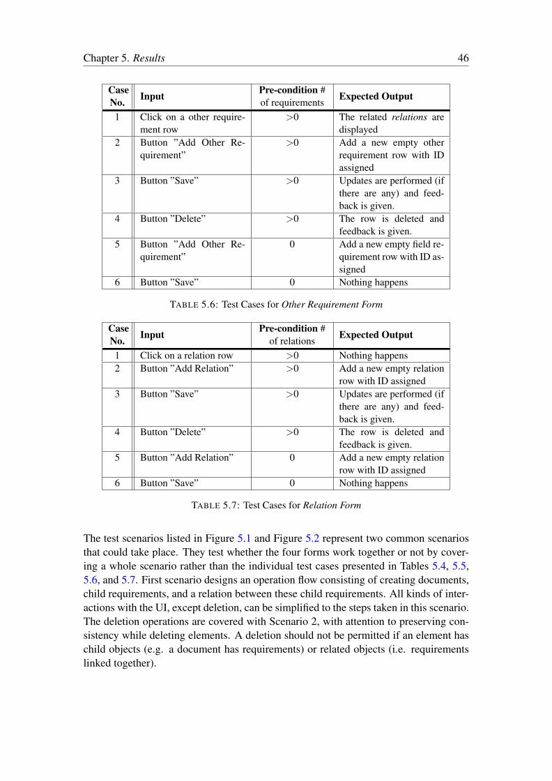
Chapter 5. Results 46
Case
No.Input
Pre-condition #of requirements Expected Output
1 Click on a other require-ment row
>0 The related relations aredisplayed
2 Button ”Add Other Re-quirement”
>0 Add a new empty otherrequirement row with IDassigned
3 Button ”Save” >0 Updates are performed (ifthere are any) and feed-back is given.
4 Button ”Delete” >0 The row is deleted andfeedback is given.
5 Button ”Add Other Re-quirement”
0 Add a new empty field re-quirement row with ID as-signed
6 Button ”Save” 0 Nothing happens
TABLE 5.6: Test Cases for Other Requirement Form
Case
No.Input
Pre-condition #of relations Expected Output
1 Click on a relation row >0 Nothing happens2 Button ”Add Relation” >0 Add a new empty relation
row with ID assigned3 Button ”Save” >0 Updates are performed (if
there are any) and feed-back is given.
4 Button ”Delete” >0 The row is deleted andfeedback is given.
5 Button ”Add Relation” 0 Add a new empty relationrow with ID assigned
6 Button ”Save” 0 Nothing happens
TABLE 5.7: Test Cases for Relation Form
The test scenarios listed in Figure 5.1 and Figure 5.2 represent two common scenariosthat could take place. They test whether the four forms work together or not by cover-ing a whole scenario rather than the individual test cases presented in Tables 5.4, 5.5,5.6, and 5.7. First scenario designs an operation flow consisting of creating documents,child requirements, and a relation between these child requirements. All kinds of inter-actions with the UI, except deletion, can be simplified to the steps taken in this scenario.The deletion operations are covered with Scenario 2, with attention to preserving con-sistency while deleting elements. A deletion should not be permitted if an element haschild objects (e.g. a document has requirements) or related objects (i.e. requirementslinked together).

Chapter 5. Results 47
1. Create two documents, 1 and 2
2. Select document 1
3. Add a requirement, A
4. Select document 2
5. Add a requirement, B
6. Select requirement B and add a relation to requirement A
7. Create the diagram
Expected outcome: During step 6, document 1 and requirement A is present on therelation row. Saving is successful. The created diagram shows the two documents and
their requirements with a link between them.FIGURE 5.1: Scenario 1 - Creation of two documents, two requirements, and a relation
1. Repeat steps 1-6 of Scenario 1 (Figure 5.1)
2. Delete one of the requirements; (A or B)
3. Delete one of the documents; (1 or 2)
4. Delete the relation
5. Delete requirement A
6. Delete document 1
Expected outcome: For steps 2 and 3, to preserve consistency, the deletion should notbe allowed. Feedback should be given to explain the error. After removing the relation
on step 4, remaining steps should be allowed.FIGURE 5.2: Scenario 2 - Preserving consistency during deletion operations
5.2 Results
The designed test cases and scenarios are performed on the tool. After collecting theinitial results, solutions are proposed for the failed tests. After implementing the solu-tions, failed tests are performed a second time. Corresponding to the test tables, the twosets of results and solutions are presented in separate tables; Table 5.8, 5.10, 5.11, 5.9.
As can be seen from the first set of results for individual tests, majority of the problemswere in displaying correct feedback after operations. A few other problems were presentsuch as the double cilck events, order of showing the feedback and completing deletions.When a button or a description textbox was clicked, rows were selected/unselected aswell which created much confusion. clickBubble binding of KnockoutJS is set to
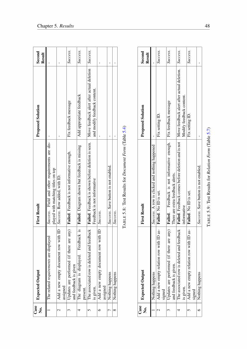
Chapter 5. Results 48
Ca
se
No
.E
xp
ecte
dO
utp
ut
Fir
st
Resu
ltP
ro
po
sed
So
luti
on
Seco
nd
Resu
lt
1Th
ere
late
dre
quir
emen
tsar
edi
spla
yed
Succ
ess.
Fiel
dan
dot
her
requ
irem
ents
are
dis-
play
edw
ithm
atch
ing
title
son
top
--
2A
dda
new
empt
ydo
cum
entr
oww
ithID
assi
gned
Succ
ess.
Row
adde
d,w
ithID
.-
-
3U
pdat
esar
epe
rfor
med
(ifth
ere
are
any)
and
feed
back
isgi
ven
Fa
iled
.Fee
dbac
kis
noti
nfor
mat
ive
enou
gh.
Fix
feed
back
mes
sage
Succ
ess.
4Th
edi
agra
mis
disp
laye
d.Fe
edba
ckis
pres
ent.
Fa
iled
.Dia
gram
show
nbu
tfee
dbac
kis
mis
sing
Add
appr
opria
tefe
edba
ckSu
cces
s.
5Th
eas
soci
ated
row
isde
lete
dan
dfe
edba
ckis
give
n.F
ail
ed
.Fee
dbac
kis
show
nbe
fore
dele
tion
isse
en.
Feed
back
isno
tinf
orm
ativ
eM
ove
feed
back
aler
tafte
ract
uald
elet
ion
and
mod
ifyfe
edba
ckco
nten
t.Su
cces
s.
6A
dda
new
empt
ydo
cum
entr
oww
ithID
assi
gned
Succ
ess.
--
7N
othi
ngha
ppen
sSu
cces
s.Sa
vebu
tton
isno
tena
bled
.-
-8
Not
hing
happ
ens
Succ
ess.
--
TAB
LE
5.8:
Test
Res
ults
forD
ocum
entF
orm
(Tab
le5.
4)
Ca
se
No
.E
xp
ecte
dO
utp
ut
Fir
st
Resu
ltP
ro
po
sed
So
luti
on
Seco
nd
Resu
lt
1N
othi
ngha
ppen
sSu
cces
s.A
row
iscl
icke
dan
dno
thin
gha
ppen
ed-
-2
Add
ane
wem
pty
rela
tion
row
with
IDas
-si
gned
Fa
iled
.No
IDis
set.
Fix
setti
ngID
.Su
cces
s.
3U
pdat
esar
epe
rfor
med
(ifth
ere
are
any)
and
feed
back
isgi
ven.
Fa
iled
.Fe
edba
ckis
not
info
rmat
ive
enou
gh.
Ther
ear
eex
trafe
edba
ckal
erts
.Fi
xfe
edba
ckm
essa
geSu
cces
s.
4Th
eas
soci
ated
row
isde
lete
dan
dfe
edba
ckis
give
n.F
ail
ed
.Fee
dbac
kco
mes
befo
rede
letio
nan
dis
not
info
rmat
ive
Mov
efe
edba
ckal
erta
ftera
ctua
ldel
etio
n.M
odify
feed
back
cont
ent.
Succ
ess.
5A
dda
new
empt
yre
latio
nro
ww
ithID
as-
sign
edF
ail
ed
.No
IDis
set.
Fix
setti
ngID
.Su
cces
s.
6N
othi
ngha
ppen
sSu
cces
s.Sa
vebu
tton
isno
tena
bled
.-
-
TAB
LE
5.9:
Test
Res
ults
forR
elat
ion
Form
(Tab
le5.
7)

Chapter 5. Results 49
Ca
se
No
.E
xp
ecte
dO
utp
ut
Fir
st
Resu
ltP
ro
po
sed
So
luti
on
Seco
nd
Resu
lt
1Th
ere
late
dre
latio
nsar
edi
spla
yed
Succ
ess.
The
rela
tions
are
show
nin
the
rela
tion
form
that
appe
ared
belo
wth
ese
lect
edro
w.
--
2A
dda
new
empt
yfie
ldre
quire
men
tro
ww
ithID
assi
gned
Succ
ess.
--
3U
pdat
esar
epe
rfor
med
(ifth
ere
are
any)
and
feed
back
isgi
ven.
Fa
iled
.Fee
dbac
kis
noti
nfor
mat
ive
enou
gh.
Fix
feed
back
mes
sage
Succ
ess.
4Th
eas
soci
ated
row
isde
lete
dan
dfe
edba
ckis
give
n.F
ail
ed
.Fee
dbac
kco
mes
befo
rede
letio
nan
dis
not
info
rmat
ive
Mov
efe
edba
ckal
erta
ftera
ctua
ldel
etio
n.M
odify
feed
back
cont
ent.
Succ
ess.
5A
dda
new
empt
yfie
ldre
quire
men
tro
ww
ithID
assi
gned
Succ
ess.
--
6N
othi
ngha
ppen
sSu
cces
s.Sa
vebu
tton
isno
tena
bled
.-
-
TAB
LE
5.10
:Tes
tRes
ults
forF
ield
Requ
irem
entF
orm
(Tab
le5.
5)
Ca
se
No
.E
xp
ecte
dO
utp
ut
Fir
st
Resu
ltP
ro
po
sed
So
luti
on
Seco
nd
Resu
lt
1Th
ere
late
dre
latio
nsar
edi
spla
yed
Succ
ess.
The
rela
tions
are
show
nin
the
rela
tion
form
that
appe
ared
belo
wth
ese
lect
edro
w.
--
2A
dda
new
empt
yfie
ldre
quire
men
tro
ww
ithID
assi
gned
Succ
ess.
--
3U
pdat
esar
epe
rfor
med
(ifth
ere
are
any)
and
feed
back
isgi
ven.
Fa
iled
.Fee
dbac
kis
noti
nfor
mat
ive
enou
gh.
Fix
feed
back
mes
sage
Succ
ess.
4Th
eas
soci
ated
row
isde
lete
dan
dfe
edba
ckis
give
n.F
ail
ed
.Fee
dbac
kco
mes
befo
rede
letio
nan
dis
not
info
rmat
ive
Mov
efe
edba
ckal
erta
ftera
ctua
ldel
etio
n.M
odify
feed
back
cont
ent.
Succ
ess.
5A
dda
new
empt
yfie
ldre
quire
men
tro
ww
ithID
assi
gned
Succ
ess.
--
6N
othi
ngha
ppen
sSu
cces
s.Sa
vebu
tton
isno
tena
bled
.-
-
TAB
LE
5.11
:Tes
tRes
ults
forO
ther
Requ
irem
entF
orm
(Tab
le5.
6)

Chapter 5. Results 50
false to suppress the click events for the rows when a button or textbox is clicked. Theempty function dummy of RootModel class is used to have a click binding so the clickis registered and clickBubble takes effect. Also, there were major problems withcorrectly creating and updating relations. After proposed solutions were implemented,the failing tests were repeated and, as seen from ”Second Result” columns, seen to befixed.
In Table 5.12 and Table 5.13, results for scenarios are presented. The first results of indi-vidual tests (on forms) were shared by them as well. These failing results were omittedto prevent repetition. Instead, only new output was listed for the scenario results. Fig-ure 5.12 show that all tests were successful for Scenario 1. However, there were majorproblems with Scenario 2. As seen in Figure 5.13, no deletion was prevented when therewere child or related elements. Although this did not create immediate problems, whensome of the individual tests were repeated, it was seen that these deletion operationsput the system in an invalid state. The repeated individual tests, such as creating andupdating elements, suffered from these allowed deletions and hence rendered scenariotests unsuccessful. After the proposed solutions are applied, second round of testing forScenario 2 has created successful results.

Chapter 5. Results 51
Ste
p
No.
Ste
pC
on
ten
tF
irst
Resu
ltP
rop
osed
Solu
tion
Secon
d
Resu
lt
1C
reat
etw
odo
cum
ents
,1an
d2
Succ
ess.
Doc
umen
tsar
ecr
eate
d.D
escr
iptio
nsar
eup
date
dan
dsa
ved.
--
2Se
lect
docu
men
t1Su
cces
s.D
ocum
enti
sse
lect
edan
dre
quire
men
tfor
ms
are
disp
laye
d.-
-3
Add
afie
ldre
quire
men
t,A
Succ
ess.
--
4Se
lect
docu
men
t2Su
cces
s.D
ocum
enti
sse
lect
edan
dre
quire
men
tfor
ms
are
disp
laye
d.-
-5
Add
anot
herr
equi
rem
ent,
BSu
cces
s.-
-6
Sele
ctre
quire
men
tBan
dad
da
rela
-tio
nto
requ
irem
entA
Succ
ess.
Ane
wro
wis
crea
ted.
IDis
set.
Doc
umen
t1an
dits
requ
ire-
men
t,A
,isd
ispl
ayed
onth
ene
wre
latio
nro
w.A
fters
elec
ting
docu
men
t1
and
requ
irem
entA
,rel
atio
nsu
cces
sful
lysa
ved.
--
7C
reat
eth
edi
agra
mSu
cces
s.C
reat
eddo
cum
ents
,the
irre
quire
men
ts,a
ndth
ere
latio
nis
vis-
ible
onth
edi
agra
m-
-
TAB
LE
5.12
:Tes
tres
ults
ofSc
enar
io1
(Fig
ure
5.1
Ste
p
No.
Ste
pC
on
ten
tF
irst
Resu
ltP
rop
osed
Solu
tion
Secon
d
Resu
lt
1R
epea
tste
ps1-
6of
Scen
ario
1(F
igur
e5.
1)Su
cces
s.-
-
2D
elet
eon
eof
the
requ
irem
ents
;(A
orB
)F
ail
ed
.Req
uire
men
tis
allo
wed
tobe
dele
ted
whi
chac
cum
ulat
edot
here
rror
s.Pr
even
tde
letio
nan
dsh
owa
feed
back
.Su
cces
s.
3D
elet
eon
eof
the
docu
men
ts;(
1or
2)F
ail
ed
.D
ocum
ent
isal
low
edto
bede
lete
dw
hich
accu
mul
ated
othe
rerr
ors.
Prev
ent
dele
tion
and
show
afe
edba
ckSu
cces
s.
4D
elet
eth
ere
latio
nSu
cces
s.-
-5
Del
ete
requ
irem
entA
Succ
ess.
--
6D
elet
edo
cum
ent1
Succ
ess.
--
TAB
LE
5.13
:Tes
tres
ults
ofSc
enar
io2
(Fig
ure
5.2

Chapter 6
Further Research Roadmap
Defining good limits for an implementation is important. To include all the desiredfunctionality at once is not feasible. So this thesis implementation is done with a spe-cific domain of systems (that elicitation is performed for) in mind. Inside this domain,the implementation’s focus is further concentrated on the migration of paper-documentsinto digital datatypes of the new system. Even further limitations were put on the imple-mentation: only a single description field is taken for each object, a hard-coded staticdatabase was used, a real remote web-server was not used, etc. In this chapter, howthese limitations could be taken back and the implementation could be extended withthese excluded features.
The selected domain of software systems was ECM systems and more specifically theelicitation process for their document digitalization process was picked as the focus.This created a comfortable subject matter for the thesis implementation. However, tobe realistically usable in a complete elicitation process, the tool need to be more gener-alized. ReqIF supports the following atomic data types:
• String A unicode text string. The maximum length can be set on the Datatype.
• Boolean A Boolean value. No customization is possible.
• Integer An integer value. The maximum and minimum can be set on the Datatype.
• Real A real value. The maximum and minimum can be set on the Datatype, aswell as the accuracy.
• Date A date- and timestamp value. No customization is possible.
• Enumeration An enumeration Datatype consists of a number of enumeration val-ues. The AttributeDefinition determines whether the values are single value ormultiple values.
52
Chapter 6. Further Research Roadmap 53
Out of these atomic data types, only String is put to use in this implementation. Asmentioned in 4, ReqIF’s SpecObjectType has a list of Attributes which gives these At-tributes to a SpecObject. These Attribute objects could encapsulate any of the atomicdatatypes listed above. Attributes are not used in this implementation. They providevery powerful customization possibilities of requirements to include different types ofattributes. In order to generalize the tool to be used for other parts of the project do-main (e.g. operational requirements), implementation of these datatypes is needed. Forexample, let’s say there is a document that the organization issues with 3 signaturesand these signatures should be provided by 3 out of 7 people who are authorized. Arequirement object that takes a number attribute would be useful here.
Another part that deserves future work is the diagramming feature. In Chapter 4, itwas mentioned that reconnecting and deleting features of links were disabled. Backingthese features instead of removing them from JointJS could introduce better usability.However, the difficulties experienced while extending and customizing JointJS inspireslooking for another diagramming solutions in the future.

Chapter 7
Conclusion
It is important to pay attention to finding correct requirements to deliver quality soft-ware systems. RL deals with gathering and structuring these requirements. Studiesshow that poor requirements elicitation is an important factor in project failures. To im-prove the quality of RL An important problem in RL is the quality of elicited require-ments. Improving quality is related to constraints such as time costs and scheduling,and organizing elicitation activities through a solid recording system. In this thesis, atool is proposed to address these issues. First, the tool is aimed to be simple and hence,usable by nonengineer stakeholders after an introduction. Second, it creates a commonenvironment which fosters requirement organization while elicitation is going on. Thecommon RL techniques mostly rely on manual note-taking during elicitation activitieswhich makes it cumbersome to structure gathered information.
The selected domain was document management systems of ECM systems. The toolconsists of a server which provides persistent storage for the data and a client-side thatis designed to help elicitation of requirements for migrating physical documents intoan ECM system. The proposed tool uses an OMG standard, ReqIF, which providesa solid backbone. The gathered requirements are kept in ReqIF data structures. Theinformation is gathered through a web-page UI that utilizes some JavaScript libraries;KnockoutJS, JointJS, jQuery. The system makes use of AJAX to ensure a smooth inter-face that does partial, fast updates.
Quality of requirements is aimed to be increased through ease-of-use, freedom of schedul-ing, and structured recording of requirements. The system could not be tested withina real project environment. However, tests on the UI was performed. The problemsfound during these tests were solved, then failed tests were repeated. In final results, alldesigned tests were successful. The future improvements for the tool are also presented.These improvements include the generalization of the tool; to use the versatility of Re-qIF standard to its full extent so its usage can be extended towards the whole ECM andultimately to other domains as well.
54

Appendix A
Implementation Code
In this appendix, selected classes of the implementation are listed.
LISTING A.1: document.html file. The single HTML page of the application.”data-bind” attributes work with Knockout.JS
<!DOCTYPE html><html><head><meta charset="UTF-8"><title>Insert title here</title><link rel="stylesheet" href="res/jointjs/joint.nojquery.css" /><link rel="stylesheet"href="res/bootstrap-3.1.1-dist/css/bootstrap.min.css" />
</head><body><div class="container">
<h1>Documents</h1><table class="table">
<thead><tr><th>ID</th><th>Title</th><th>Delete</th>
</tr></thead><tbody data-bind="foreach: documents">
<trdata-bind="click: $root.selectDocument, css: { active: $root.selectedDocument() == $data}"><td data-bind="text: id"></td><td><input type="text" style="cursor: pointer"
placeholder="Enter description..." data-bind="click: $root.dummy, value: description, clickBubble:false"></td>
<td><input type="button" value="Delete"class="btn btn-small btn-danger"data-bind="click: $root.deleteDocument.bind($data), clickBubble: false" /></td>
</tr></tbody>
</table><input type="button" class="btn btn-small btn-primary"
data-bind="{ click: addDocument, value: ’Add Document’ }" /> <inputtype="button" class="btn btn-small btn-primary"data-bind="{ click: saveDocuments, value: ’Save’ }" /> <inputtype="button" value="Diagram" class="btn btn-small btn-primary"data-bind="click: $root.generateDiagram" />
</div><div class="container" data-bind="with: selectedDocument">
<h2>Field Requirements of <span
data-bind="text: description"></span></h2><table class="table"
data-bind="visible: fieldRequirements().length"><thead>
<tr><th>ID</th><th>Description</th><th>Delete</th>
</tr></thead>
55

Appendix A. Appendix Title Here 56
<tbody data-bind="foreach: fieldRequirements"><trdata-bind="click: $root.selectSpecObject.bind($data), css: { active: $root.selectedSpecObject() == $data
}"><td data-bind="text: id"></td><td><input type="text" style="cursor: pointer"
placeholder="Enter description..." data-bind="click: $root.dummy, value: description, clickBubble:false"></td>
<td><input type="button" value="Delete"class="btn btn-small btn-danger"data-bind="click: $root.deleteSpecObject.bind($data), clickBubble: false" /></td>
</tr><tr data-bind="visible: $root.selectedSpecObject() == $data"><td></td><td colspan="2">
<div class="container"><table class="table"data-bind="visible: $root.showedRelations().length"><thead>
<tr><th>ID</th><th>Description</th><th>Linked Document</th><th>Linked Requirement</th><th>Delete</th>
</tr></thead><tbody data-bind="foreach: $root.showedRelations">
<tr><td data-bind="text: id"></td><td><input type="text" style="cursor: pointer"
placeholder="Enter description..."data-bind="value: description"></td>
<td><select class="form-control" id="document"data-bind="
options: $root.documents,optionsText: function(item) {
return item.description;},optionsCaption: ’Select a document...’,value: linkedDoc"></select></td>
<td data-bind="with: linkedDoc"><select class="form-control" id="requirement"data-bind="
options: allRequirements,optionsText: function(item) {
return item.description;},optionsCaption: ’Select a requirement...’,value: $parent.linkedTo,visible: allRequirements().length > 0"></select>
</td><td><input type="button" value="Delete"
class="btn btn-small btn-danger"data-bind="click: $root.deleteRelation.bind($data)" /></td>
</tr></tbody>
</table><input type="button" class="btn btn-small btn-primary"
data-bind="{click: $root.addRelation, value: ’Add Relation’}" /><input type="button" class="btn btn-small btn-primary"
data-bind="{ click: $root.saveRelations, value: ’Save’, enable: $root.showedRelations().length }"/>
</div></td>
</tr></tbody>
</table><input type="button" class="btn btn-small btn-primary"data-bind="{ click: $root.addFieldRequirement, value: ’Add Field Requirement’ }" />
<input type="button" class="btn btn-small btn-primary"data-bind="{ click: $root.saveFieldSpecObjects, value: ’Save’, enable: fieldRequirements().length }" />
<h2>Other Requirements of <span
data-bind="text: description"></span></h2><table class="table"data-bind="visible: otherRequirements().length"><thead>
<tr><th>ID</th><th>Description</th><th>Delete</th>
</tr></thead><tbody data-bind="foreach: otherRequirements">
<trdata-bind="click: $root.selectSpecObject.bind($data), css: { active: $root.selectedSpecObject() == $data
}"><td data-bind="text: id"></td><td><input type="text" style="cursor: pointer"
placeholder="Enter description..." data-bind="click: $root.dummy, value: description, clickBubble:false"></td>
<td><input type="button" value="Delete"class="btn btn-small btn-danger"data-bind="click: $root.deleteSpecObject.bind($data), clickBubble: false" /></td>

Appendix A. Appendix Title Here 57
</tr><tr data-bind="visible: $root.selectedSpecObject() == $data"><td></td><td colspan="2">
<div class="container"><table class="table"data-bind="visible: $root.showedRelations().length"><thead>
<tr><th>ID</th><th>Description</th><th>Linked Document</th><th>Linked Requirement</th><th>Delete</th>
</tr></thead><tbody data-bind="foreach: $root.showedRelations">
<tr><td data-bind="text: id"></td><td><input type="text" style="cursor: pointer"
placeholder="Enter description..."data-bind="value: description"></td>
<td><select class="form-control" id="document"data-bind="
options: $root.documents,optionsText: function(item) {
return item.description;},optionsCaption: ’Select a document...’,value: linkedDoc"></select></td>
<td data-bind="with: linkedDoc"><select class="form-control" id="requirement"data-bind="
options: allRequirements,optionsText: function(item) {
return item.description;},optionsCaption: ’Select a requirement...’,value: $parent.linkedTo,visible: allRequirements().length > 0"></select>
</td><td><input type="button" value="Delete"
class="btn btn-small btn-danger"data-bind="click: $root.deleteRelation.bind($data)" /></td>
</tr></tbody>
</table><input type="button" class="btn btn-small btn-primary"
data-bind="{click: $root.addRelation, value: ’Add Relation’}" /><input type="button" class="btn btn-small btn-primary"
data-bind="{ click: $root.saveRelations, value: ’Save’, enable: $root.showedRelations().length }"/>
</div></td>
</tr></tbody>
</table><input type="button" class="btn btn-small btn-primary"
data-bind="{ click: $root.addOtherRequirement, value: ’Add Other Requirement’ }" /><input type="button" class="btn btn-small btn-primary"
data-bind="{ click: $root.saveOtherSpecObjects, value: ’Save’, enable: otherRequirements().length }" /></div>
<div id="myholder"></div>
<script type="text/javascript" src="res/jquery-2.1.0.js"></script><script type="text/javascript" src="res/jointjs/joint.nojquery.js"></script><script type="text/javascript" src="res/jointjs/joint.shapes.uml.js"></script><script type="text/javascript" src="res/jointjs/joint.reqif.js"></script><script type="text/javascript"
src="res/bootstrap-3.1.1-dist/js/bootstrap.min.js"></script><script type="text/javascript" src="res/knockout-3.1.0.js"></script><script type="text/javascript" src="res/document-models.js"></script>
</body></html>
LISTING A.2: document-models.js file. Constitutes View Model part of MVVM ar-chitecture of KnockoutJS. Talks with server-side through AJAX calls and provides
JavaScript models to bind to document.html (A.1).var canvaswidth = 800;var canvasheight = 600;
var graph = new joint.dia.Graph;
var paper = new joint.dia.Paper({el : $(’#myholder’),width : canvaswidth,height : canvasheight,

Appendix A. Appendix Title Here 58
gridSize : 1,model : graph,perpendicularLinks : true
});
var findJointjsObject = function(arr, reqifID) {for (var i = 0; i < arr.length; i++) {
if (arr[i].attributes.reqifID == reqifID)return arr[i];
}return null;
};
var findSpec = function(docs, specId) {for (var i = 0; i < docs.length; i++) {
for (var j = 0; j < docs[i].fieldRequirements().length; j++) {if (docs[i].fieldRequirements()[j].id() == specId)
return docs[i].fieldRequirements()[j];}for (var k = 0; k < docs[i].otherRequirements().length; k++) {
if (docs[i].otherRequirements()[k].id() == specId)return docs[i].otherRequirements()[k];
}}return null;
};
function RootModel() {var self = this;
self.rootObj = ko.observable();self.documents = ko.observableArray();self.relations = ko.observableArray();
self.selectedDocument = ko.observable();self.selectedSpecObject = ko.observable();self.showedRelations = ko.observableArray();
self.dummy = function() { },
self.getDocumentById = function(id) {for (var i = 0; i < self.documents().length; i++) {if (self.documents()[i].id() == id)
return self.documents()[i];}return null;
},
self.setRoot = function(root) {self.rootObj(new Root(root));self.documents.removeAll();for (var i = 0; i < root.documents.length; i++)self.documents.push(new Document(root.documents[i]));
self.relations([]);for (i = 0; i < root.relations.length; i++) {var rel = new SpecRelation();rel.id(root.relations[i].id);rel.description = root.relations[i].description;rel.source(findSpec(self.documents(), root.relations[i].source));rel.target(findSpec(self.documents(), root.relations[i].target));rel.linkedFrom(rel.source());rel.linkedTo(rel.target());self.relations.push(rel);
}},
// Insert Rowself.addDocument = function() {
var doc = new Document();self.documents.push(doc);self.ajaxSaveDocument(doc);
},
self.addFieldRequirement = function() {var specobject = new SpecObject(self.selectedDocument().id);self.selectedDocument().fieldRequirements.push(specobject);self.ajaxSaveSpecObject(specobject, ’true’);
},
self.addOtherRequirement = function() {var specobject = new SpecObject(self.selectedDocument().id);self.selectedDocument().otherRequirements.push(specobject);self.ajaxSaveSpecObject(specobject, ’false’);
},
self.addRelation = function() {var rel = new SpecRelation();rel.source(self.selectedSpecObject());rel.linkedFrom(self.selectedSpecObject());self.showedRelations.push(rel);self.relations.push(rel);self.ajaxSaveSpecRelation(rel);
},

Appendix A. Appendix Title Here 59
// Select Rowself.selectDocument = function(document) {
if (self.selectedDocument() == document)self.selectedDocument(null);
else {self.selectedDocument(document);
}},
self.selectSpecObject = function(specObject) {if (self.selectedSpecObject() == specObject) {
self.selectedSpecObject(null);self.showedRelations([]);
} else {self.selectedSpecObject(specObject);
self.showedRelations(self.getRelatedRelations(specObject));
}},
self.getRelatedRelations = function(specObject) {var arr = [];for (var i = 0; i < self.relations().length; i++) {
if (self.relations()[i].source() == specObject) {self.relations()[i].linkedDoc(self.getDocumentById(self.relations()[i].target().docId));self.relations()[i].linkedTo(self.relations()[i].target());self.relations()[i].linkedFrom(self.relations()[i].source());arr.push(self.relations()[i]);
}if (self.relations()[i].target() == specObject) {
self.relations()[i].linkedDoc(self.getDocumentById(self.relations()[i].source().docId));self.relations()[i].linkedTo(self.relations()[i].source());self.relations()[i].linkedFrom(self.relations()[i].target());arr.push(self.relations()[i]);
}}return arr;
},
// Saving Gridself.saveDocuments = function() {
for (var i = 0; i < self.documents().length; i++) {self.ajaxSaveDocument(self.documents()[i]);
}},
self.saveFieldSpecObjects = function() {for (var i = 0; i < self.selectedDocument().fieldRequirements().length; i++) {
self.ajaxSaveSpecObject(self.selectedDocument().fieldRequirements()[i], ’true’);}
},
self.saveOtherSpecObjects = function() {for (var i = 0; i < self.selectedDocument().otherRequirements().length; i++) {self.ajaxSaveSpecObject(self.selectedDocument().otherRequirements()[i], ’false’);
}},
self.saveRelations = function() {for (var i = 0; i < self.showedRelations().length; i++) {self.ajaxSaveSpecRelation(self.showedRelations()[i]);
}},
// Deletionself.deleteDocument = function(document) {
if (document.fieldRequirements().length != 0 || document.otherRequirements().length != 0) {alert(’Document has requirements and cannot be deleted! Delete requirements first!’);return;
}
if (document.id() != null) {self.ajaxDeleteDocument(document);
}else {self.documents.remove(document);alert(’Document deleted! Description: ’ + document.description);
}},
self.deleteSpecObject = function(specObject) {if (self.getRelatedRelations(specObject).length != 0) {alert(’Requirement has relations and cannot be deleted! Delete relations first!’);return;
}
if (specObject.id() != null) {self.ajaxDeleteSpecObject(self.selectedDocument(), specObject);
}else {document.fieldRequirements.remove(spec);document.otherRequirements.remove(spec);alert(’Requirement deleted! Description: ’ + spec.description);
}
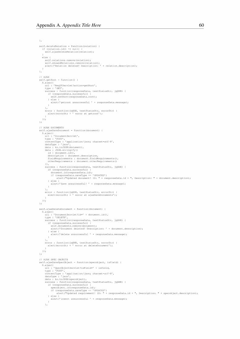
Appendix A. Appendix Title Here 60
},
self.deleteRelation = function(relation) {if (relation.id() != null) {
self.ajaxDeleteRelation(relation);}else {
self.relations.remove(relation);self.showedRelations.remove(relation);alert(’Relation deleted! Description: ’ + relation.description);
}},
// AJAXself.getRoot = function() {
$.ajax({url : ’ReqIFServlet?action=getRoot’,type : ’GET’,success : function(responseData, textStatusStr, jqXHR) {
if (responseData.successful) {self.setRoot(responseData.root);
} else {alert(’getroot unsuccessful ’ + responseData.message);
}},error : function(jqXHR, textStatusStr, errorStr) {
alert(errorStr + ’ error at getroot’);}
});};
// AJAX DOCUMENTSself.ajaxSaveDocument = function(document) {
$.ajax({url : ’DocumentServlet’,type : ’POST’,contentType : ’application/json; charset=utf-8’,dataType : ’json’,data : ko.toJSON(document),data : JSON.stringify({
id : document.id(),description : document.description,fieldRequirements : document.fieldRequirements(),otherRequirements : document.otherRequirements()
}),success : function(responseData, textStatusStr, jqXHR) {
if (responseData.successful) {document.id(responseData.id);if (responseData.saveType == ’UPDATED’)
alert("Updated document! ID: " + responseData.id + ", Description: " + document.description);} else {alert(’Save unsuccessful! ’ + responseData.message);
}},error : function(jqXHR, textStatusStr, errorStr) {
alert(errorStr + ’ error at ajaxSaveDocuments’);}
});};
self.ajaxDeleteDocument = function(document) {$.ajax({
url : ’DocumentServlet?id=’ + document.id(),type : ’DELETE’,success : function(responseData, textStatusStr, jqXHR) {
if (responseData.successful) {self.documents.remove(document);alert(’Document deleted! Description: ’ + document.description);
} else {alert(’delete unsuccessful ’ + responseData.message);
}},error : function(jqXHR, textStatusStr, errorStr) {
alert(errorStr + ’ error at deleteDocument’);}
});};
// AJAX SPEC OBJECTSself.ajaxSaveSpecObject = function(specobject, isfield) {
$.ajax({url : ’SpecObjectServlet?isField=’ + isfield,type : ’POST’,contentType : ’application/json; charset=utf-8’,dataType : ’json’,data : ko.toJSON(specobject),success : function(responseData, textStatusStr, jqXHR) {
if (responseData.successful) {specobject.id(responseData.id);if (responseData.saveType == ’UPDATED’)
alert("Updated requirement! ID: " + responseData.id + ", Description: " + specobject.description);} else {alert(’insert unsuccessful ’ + responseData.message);
}},

Appendix A. Appendix Title Here 61
error : function(jqXHR, textStatusStr, errorStr) {alert(errorStr + ’ error at insertSpecObject’);
}});
};
self.ajaxDeleteSpecObject = function(document, spec) {$.ajax({
url : ’SpecObjectServlet?id=’ + spec.id() + ’&docID=’ + document.id(),type : ’DELETE’,success : function(responseData, textStatusStr, jqXHR) {
if (responseData.successful) {
document.fieldRequirements.remove(spec);document.otherRequirements.remove(spec);alert(’Requirement deleted! Description: ’ + spec.description);
} else {alert(’delete unsuccessful ’ + responseData.message);
}},error : function(jqXHR, textStatusStr, errorStr) {
alert(errorStr + ’ error at deleteSpecObject’);}
});};
// AJAX RELATIONSself.ajaxSaveSpecRelation = function(relation) {
$.ajax({url : ’SpecRelationServlet’,type : ’POST’,contentType : ’application/json; charset=utf-8’,dataType : ’json’,data : JSON.stringify({
id : relation.id(),description : relation.description,source : relation.linkedFrom().id(),target : relation.linkedTo() ? relation.linkedTo().id() : ’0’
}),success : function(responseData, textStatusStr, jqXHR) {
if (responseData.successful) {relation.id(responseData.id);relation.target(relation.linkedTo());if (responseData.saveType == ’UPDATED’)
alert("Updated relation! ID: " + responseData.id + ", Description: " + relation.description);} else {alert(’insert unsuccessful ’ + responseData.message);
}},error : function(jqXHR, textStatusStr, errorStr) {
alert(errorStr + ’ error at ajaxInsertRelation’);}
});};
self.ajaxDeleteRelation = function(relation) {$.ajax({
url : ’SpecRelationServlet?id=’ + relation.id(),type : ’DELETE’,success : function(responseData, textStatusStr, jqXHR) {
if (responseData.successful) {self.relations.remove(relation);self.showedRelations.remove(relation);alert(’Relation deleted! Description: ’ + relation.description);
} else {alert(’delete unsuccessful ’ + responseData.message);
}},error : function(jqXHR, textStatusStr, errorStr) {
alert(errorStr + ’ error at ajaxDeleteRelation’);}
});};
// Diagram functionself.generateDiagram = function() {
graph.resetCells();var docsJS = ko.toJS(self.documents);var reqs = [];for (var i = 0; i < docsJS.length; i++) {var fieldReqs = [];_.each(docsJS[i].fieldRequirements, function(c) {
fieldReqs.push(new reqif.Requirement({reqifID : c.id,description : c.description
}));});
var otherReqs = [];_.each(docsJS[i].otherRequirements, function(c) {
otherReqs.push(new reqif.Requirement({reqifID : c.id,description : c.description
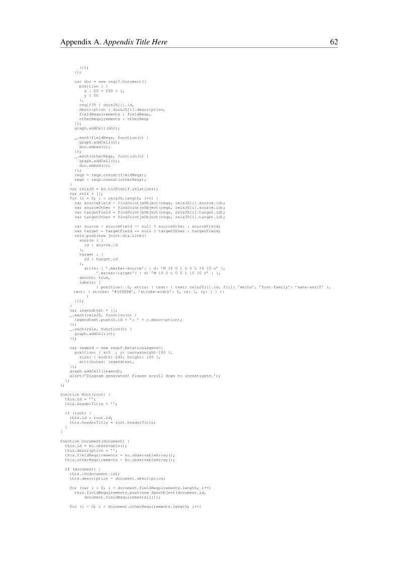
Appendix A. Appendix Title Here 62
}));});
var doc = new reqif.Document({position : {x : 20 + 250 * i,y : 50
},reqifID : docsJS[i].id,description : docsJS[i].description,fieldRequirements : fieldReqs,otherRequirements : otherReqs
});graph.addCell(doc);
_.each(fieldReqs, function(c) {graph.addCell(c);doc.embed(c);
});_.each(otherReqs, function(c) {
graph.addCell(c);doc.embed(c);
});reqs = reqs.concat(fieldReqs);reqs = reqs.concat(otherReqs);
}var relsJS = ko.toJS(self.relations);var rels = [];for (i = 0; i < relsJS.length; i++) {
var sourceField = findJointjsObject(reqs, relsJS[i].source.id);var sourceOther = findJointjsObject(reqs, relsJS[i].source.id);var targetField = findJointjsObject(reqs, relsJS[i].target.id);var targetOther = findJointjsObject(reqs, relsJS[i].target.id);
var source = sourceField == null ? sourceOther : sourceField;var target = targetField == null ? targetOther : targetField;rels.push(new joint.dia.Link({
source : {id : source.id
},target : {id : target.id
},attrs: { ’.marker-source’: { d: ’M 10 0 L 0 5 L 10 10 z’ },
’.marker-target’: { d: ’M 10 0 L 0 5 L 10 10 z’ } },smooth: true,labels: [
{ position: .5, attrs: { text: { text: relsJS[i].id, fill: ’white’, ’font-family’: ’sans-serif’ },rect: { stroke: ’#3498DB’, ’stroke-width’: 5, rx: 1, ry: 1 } }}
]}));
}var legendtext = [];_.each(relsJS, function(c) {legendtext.push(c.id + ’: ’ + c.description);
});_.each(rels, function(c) {graph.addCell(c);
});
var legend = new reqif.RelationLegend({position: { x:0 , y: canvasheight-100 },
size: { width: 240, height: 100 },attributes: legendtext,
});graph.addCell(legend);alert(’Diagram generated! Please scroll down to investigate.’);
};};
function Root(root) {this.id = ’’;this.headerTitle = ’’;
if (root) {this.id = root.id;this.headerTitle = root.headerTitle;
}}
function Document(document) {this.id = ko.observable();this.description = ’’;this.fieldRequirements = ko.observableArray();this.otherRequirements = ko.observableArray();
if (document) {this.id(document.id);this.description = document.description;
for (var i = 0; i < document.fieldRequirements.length; i++)this.fieldRequirements.push(new SpecObject(document.id,
document.fieldRequirements[i]));
for (i = 0; i < document.otherRequirements.length; i++)
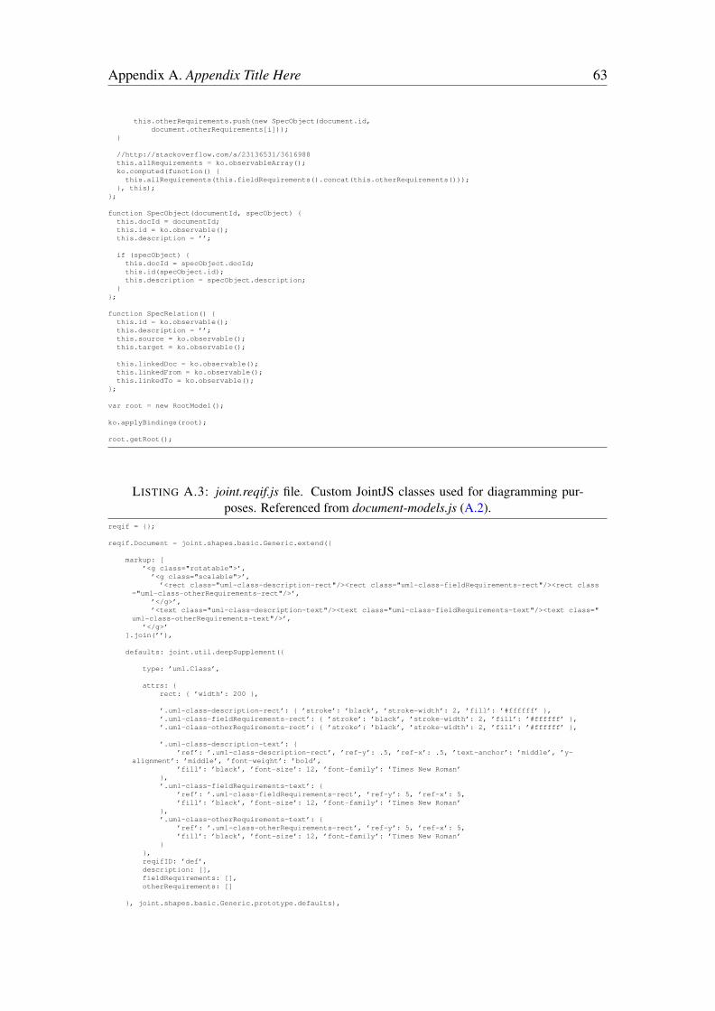
Appendix A. Appendix Title Here 63
this.otherRequirements.push(new SpecObject(document.id,document.otherRequirements[i]));
}
//http://stackoverflow.com/a/23136531/3616988this.allRequirements = ko.observableArray();ko.computed(function() {
this.allRequirements(this.fieldRequirements().concat(this.otherRequirements()));}, this);
};
function SpecObject(documentId, specObject) {this.docId = documentId;this.id = ko.observable();this.description = ’’;
if (specObject) {this.docId = specObject.docId;this.id(specObject.id);this.description = specObject.description;
}};
function SpecRelation() {this.id = ko.observable();this.description = ’’;this.source = ko.observable();this.target = ko.observable();
this.linkedDoc = ko.observable();this.linkedFrom = ko.observable();this.linkedTo = ko.observable();
};
var root = new RootModel();
ko.applyBindings(root);
root.getRoot();
LISTING A.3: joint.reqif.js file. Custom JointJS classes used for diagramming pur-poses. Referenced from document-models.js (A.2).
reqif = {};
reqif.Document = joint.shapes.basic.Generic.extend({
markup: [’<g class="rotatable">’,’<g class="scalable">’,
’<rect class="uml-class-description-rect"/><rect class="uml-class-fieldRequirements-rect"/><rect class="uml-class-otherRequirements-rect"/>’,
’</g>’,’<text class="uml-class-description-text"/><text class="uml-class-fieldRequirements-text"/><text class="
uml-class-otherRequirements-text"/>’,’</g>’
].join(’’),
defaults: joint.util.deepSupplement({
type: ’uml.Class’,
attrs: {rect: { ’width’: 200 },
’.uml-class-description-rect’: { ’stroke’: ’black’, ’stroke-width’: 2, ’fill’: ’#ffffff’ },’.uml-class-fieldRequirements-rect’: { ’stroke’: ’black’, ’stroke-width’: 2, ’fill’: ’#ffffff’ },’.uml-class-otherRequirements-rect’: { ’stroke’: ’black’, ’stroke-width’: 2, ’fill’: ’#ffffff’ },
’.uml-class-description-text’: {’ref’: ’.uml-class-description-rect’, ’ref-y’: .5, ’ref-x’: .5, ’text-anchor’: ’middle’, ’y-
alignment’: ’middle’, ’font-weight’: ’bold’,’fill’: ’black’, ’font-size’: 12, ’font-family’: ’Times New Roman’
},’.uml-class-fieldRequirements-text’: {
’ref’: ’.uml-class-fieldRequirements-rect’, ’ref-y’: 5, ’ref-x’: 5,’fill’: ’black’, ’font-size’: 12, ’font-family’: ’Times New Roman’
},’.uml-class-otherRequirements-text’: {
’ref’: ’.uml-class-otherRequirements-rect’, ’ref-y’: 5, ’ref-x’: 5,’fill’: ’black’, ’font-size’: 12, ’font-family’: ’Times New Roman’
}},reqifID: ’def’,description: [],fieldRequirements: [],otherRequirements: []
}, joint.shapes.basic.Generic.prototype.defaults),

Appendix A. Appendix Title Here 64
initialize: function() {
_.bindAll(this, ’updateRectangles’);
this.on(’change:description change:fieldRequirements change:otherRequirements’, function() {this.updateRectangles();
this.trigger(’uml-update’);});
this.updateRectangles();
joint.shapes.basic.Generic.prototype.initialize.apply(this, arguments);},
getClassName: function() {return this.get(’description’);
},
updateRectangles: function() {
var attrs = this.get(’attrs’);
var rects = [{ type: ’description’, text: this.getClassName() },{ type: ’fieldRequirements’, text: this.get(’fieldRequirements’) },{ type: ’otherRequirements’, text: this.get(’otherRequirements’) }
];
var offsetY = 0;
_.each(rects, function(rect) {
var lines = _.isArray(rect.text) ? rect.text : [rect.text];var rectHeight = lines.length * 20 + 10;
attrs[’.uml-class-’ + rect.type + ’-text’].text = _.isArray(rect.text) ? ’’ : lines.join(’\n’);attrs[’.uml-class-’ + rect.type + ’-rect’].height = rectHeight;attrs[’.uml-class-’ + rect.type + ’-rect’].transform = ’translate(0,’+ offsetY + ’)’;
offsetY += rectHeight;});
var reqoffset = this.attributes.position.y + attrs[’.uml-class-’ + ’description’ + ’-rect’].height + 3;
for (var i = 0; i < rects[1].text.length; i++) {rects[1].text[i].attributes.position.x = this.attributes.position.x;rects[1].text[i].attributes.position.y = reqoffset;reqoffset += 22;
}
reqoffset += 3;
for (var i = 0; i < rects[2].text.length; i++) {rects[2].text[i].attributes.position.x = this.attributes.position.x;rects[2].text[i].attributes.position.y = reqoffset;reqoffset += 22;
}
this.attributes.size.height = offsetY;this.attributes.size.width = attrs.rect[’width’];
}
});
reqif.Requirement = joint.shapes.basic.Generic.extend({
markup: [’<g class="rotatable">’,’<g class="scalable">’,
’<rect class="uml-class-description-rect"/>’,’</g>’,’<text class="uml-class-description-text"/>’,
’</g>’].join(’’),
defaults: joint.util.deepSupplement({
type: ’uml.Class’,
attrs: {rect: { ’width’: 200 },
’.uml-class-description-rect’: { ’stroke’: ’black’, ’stroke-width’: 2, ’fill’: ’#ffffff’ },
’.uml-class-description-text’: {’ref’: ’.uml-class-description-rect’, ’ref-y’: 5, ’ref-x’: 5,’fill’: ’black’, ’font-size’: 12, ’font-family’: ’Times New Roman’,’cursor’: ’pointer’
}},
reqifID: ’def’,description: []
}, joint.shapes.basic.Generic.prototype.defaults),

Appendix A. Appendix Title Here 65
initialize: function() {
_.bindAll(this, ’updateRectangles’);
this.on(’change:description’, function() {this.updateRectangles();
this.trigger(’uml-update’);});
this.updateRectangles();
joint.shapes.basic.Generic.prototype.initialize.apply(this, arguments);},
updateRectangles: function() {var attrs = this.get(’attrs’);
var rects = [{ type: ’description’, text: this.get(’description’) }
];
var offsetY = 0;
_.each(rects, function(rect) {
var lines = _.isArray(rect.text) ? rect.text : [rect.text];var rectHeight = lines.length * 20 + 2;
attrs[’.uml-class-’ + rect.type + ’-text’].text = lines.join(’\n’);attrs[’.uml-class-’ + rect.type + ’-rect’].height = rectHeight;attrs[’.uml-class-’ + rect.type + ’-rect’].transform = ’translate(0,’+ offsetY + ’)’;
offsetY += rectHeight;});
this.attributes.size.height = offsetY;this.attributes.size.width = attrs.rect[’width’];
}});
reqif.RelationLegend = joint.shapes.basic.Generic.extend({
markup: [’<g class="rotatable">’,’<g class="scalable">’,
’<rect class="uml-class-name-rect"/><rect class="uml-class-attrs-rect"/>’,’</g>’,’<text class="uml-class-name-text"/><text class="uml-class-attrs-text"/>’,
’</g>’].join(’’),
defaults: joint.util.deepSupplement({
type: ’uml.Class’,
attrs: {rect: { ’width’: 200 },
’.uml-class-name-rect’: { ’stroke’: ’black’, ’stroke-width’: 2, ’fill’: ’#ffffff’ },’.uml-class-attrs-rect’: { ’stroke’: ’black’, ’stroke-width’: 2, ’fill’: ’#ffffff’ },
’.uml-class-name-text’: {’ref’: ’.uml-class-name-rect’, ’ref-y’: .5, ’ref-x’: .5, ’text-anchor’: ’middle’, ’y-alignment’: ’
middle’, ’font-weight’: ’bold’,’fill’: ’black’, ’font-size’: 12, ’font-family’: ’Times New Roman’
},’.uml-class-attrs-text’: {
’ref’: ’.uml-class-attrs-rect’, ’ref-y’: 5, ’ref-x’: 5,’fill’: ’black’, ’font-size’: 12, ’font-family’: ’Times New Roman’
}},
name: ’Relation Legend’,attributes: []
}, joint.shapes.basic.Generic.prototype.defaults),
initialize: function() {
_.bindAll(this, ’updateRectangles’);
this.on(’change:name change:attributes’, function() {this.updateRectangles();
this.trigger(’uml-update’);});
this.updateRectangles();
joint.shapes.basic.Generic.prototype.initialize.apply(this, arguments);},
getClassName: function() {return this.get(’name’);
},

Appendix A. Appendix Title Here 66
updateRectangles: function() {
var attrs = this.get(’attrs’);
var rects = [{ type: ’name’, text: this.getClassName() },{ type: ’attrs’, text: this.get(’attributes’) }
];
var offsetY = 0;
_.each(rects, function(rect) {
var lines = _.isArray(rect.text) ? rect.text : [rect.text];var rectHeight = lines.length * 20 + 2;
attrs[’.uml-class-’ + rect.type + ’-text’].text = lines.join(’\n’);attrs[’.uml-class-’ + rect.type + ’-rect’].height = rectHeight;attrs[’.uml-class-’ + rect.type + ’-rect’].transform = ’translate(0,’+ offsetY + ’)’;
offsetY += rectHeight;});
this.attributes.size.height = offsetY;this.attributes.size.width = attrs.rect[’width’];
}});
LISTING A.4: SpecObjectReqIF.java file. One of the four wrapper classes presentedin Chapter 4.
package com.ozgurkadir.backend;
import org.eclipse.rmf.reqif10.ReqIF10Factory;import org.eclipse.rmf.reqif10.SpecObject;import org.eclipse.rmf.reqif10.SpecObjectType;
public class SpecObjectReqIF {
private SpecObject obj;private String docId;
public SpecObjectReqIF() {this.obj = ReqIF10Factory.eINSTANCE.createSpecObject();
}
public SpecObjectReqIF(SpecObject spec) {this.obj = spec;
}
public String getID() {return obj.getIdentifier();
}
public void setID(String id) {obj.setIdentifier(id);
}
public String getDocId() {return docId;
}
public void setDocId(String docId) {this.docId = docId;
}
public String getDescription() {return obj.getDesc();
}
public void setDescription(String s) {obj.setDesc(s);
}
protected SpecObjectType getType() {return obj.getType();
}
public void setType(SpecObjectType type) {obj.setType(type);
}protected SpecObject getObj() {
return obj;}
}
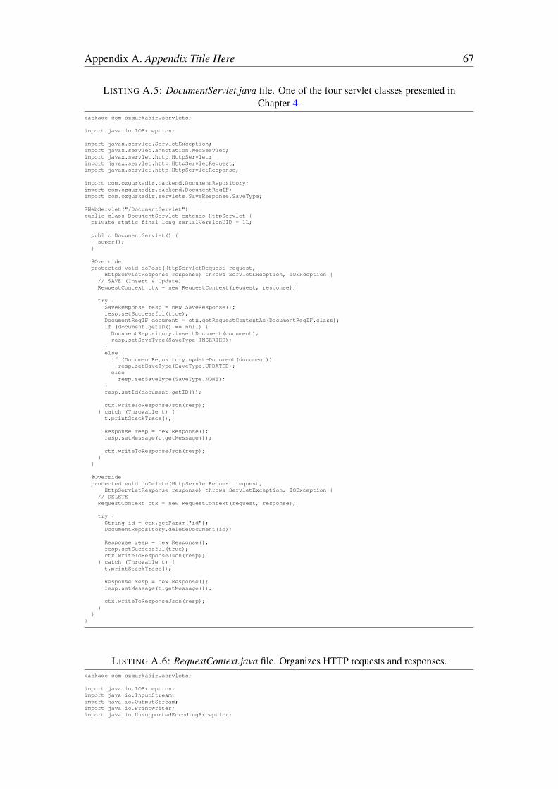
Appendix A. Appendix Title Here 67
LISTING A.5: DocumentServlet.java file. One of the four servlet classes presented inChapter 4.
package com.ozgurkadir.servlets;
import java.io.IOException;
import javax.servlet.ServletException;import javax.servlet.annotation.WebServlet;import javax.servlet.http.HttpServlet;import javax.servlet.http.HttpServletRequest;import javax.servlet.http.HttpServletResponse;
import com.ozgurkadir.backend.DocumentRepository;import com.ozgurkadir.backend.DocumentReqIF;import com.ozgurkadir.servlets.SaveResponse.SaveType;
@WebServlet("/DocumentServlet")public class DocumentServlet extends HttpServlet {private static final long serialVersionUID = 1L;
public DocumentServlet() {super();
}
@Overrideprotected void doPost(HttpServletRequest request,
HttpServletResponse response) throws ServletException, IOException {// SAVE (Insert & Update)RequestContext ctx = new RequestContext(request, response);
try {SaveResponse resp = new SaveResponse();resp.setSuccessful(true);DocumentReqIF document = ctx.getRequestContentAs(DocumentReqIF.class);if (document.getID() == null) {
DocumentRepository.insertDocument(document);resp.setSaveType(SaveType.INSERTED);
}else {
if (DocumentRepository.updateDocument(document))resp.setSaveType(SaveType.UPDATED);
elseresp.setSaveType(SaveType.NONE);
}resp.setId(document.getID());
ctx.writeToResponseJson(resp);} catch (Throwable t) {
t.printStackTrace();
Response resp = new Response();resp.setMessage(t.getMessage());
ctx.writeToResponseJson(resp);}
}
@Overrideprotected void doDelete(HttpServletRequest request,
HttpServletResponse response) throws ServletException, IOException {// DELETERequestContext ctx = new RequestContext(request, response);
try {String id = ctx.getParam("id");DocumentRepository.deleteDocument(id);
Response resp = new Response();resp.setSuccessful(true);ctx.writeToResponseJson(resp);
} catch (Throwable t) {t.printStackTrace();
Response resp = new Response();resp.setMessage(t.getMessage());
ctx.writeToResponseJson(resp);}
}}
LISTING A.6: RequestContext.java file. Organizes HTTP requests and responses.package com.ozgurkadir.servlets;
import java.io.IOException;import java.io.InputStream;import java.io.OutputStream;import java.io.PrintWriter;import java.io.UnsupportedEncodingException;

Appendix A. Appendix Title Here 68
import java.util.HashMap;import java.util.Map;
import javax.servlet.http.HttpServletRequest;import javax.servlet.http.HttpServletResponse;
import com.ozgurkadir.utils.Util;
public class RequestContext {private final HttpServletRequest request;private final HttpServletResponse response;private final InputStream requestStream;private final OutputStream responseStream;
private Map<String, String> params;
public RequestContext(HttpServletRequest request, HttpServletResponse response) throws IOException {this.request = request;this.response = response;
this.requestStream = request.getInputStream();this.responseStream = response.getOutputStream();
try {this.request.setCharacterEncoding("utf-8");this.response.setCharacterEncoding("utf-8");
} catch (UnsupportedEncodingException e) {
}
this.setResponseContentType("text/plain; charset=utf-8");}
public String getParam(String key) {if (params == null) {
params = new HashMap<String, String>();
String queryString = request.getQueryString();String[] pairs = queryString.split("&");
for (String pair : pairs) {String[] keyValue = pair.split("=");params.put(keyValue[0], Util.Misc.decodeUrl(keyValue[1]));
}}return params.get(key);
}
public <T> T getRequestContentAs(Class<T> clazz) throws IOException {this.setResponseContentType("application/json; charset=utf-8");
JsonEncoder<T> encoder = new JsonEncoder<T>(clazz);return encoder.decode(Util.IO.readUtf8String(requestStream));
}
@SuppressWarnings("unchecked")public <T> void writeToResponseJson(T responseObject) throws IOException {
this.setResponseContentType("application/json; charset=utf-8");
JsonEncoder<T> encoder = new JsonEncoder<T>((Class<T>)responseObject.getClass());String json = encoder.encode(responseObject);
PrintWriter out = new PrintWriter(responseStream);out.print(json);out.flush();
}
public void setResponseContentType(String contentTypeHeader) {this.response.setContentType(contentTypeHeader);
}}
LISTING A.7: Response.java file. Wraps a response object.package com.ozgurkadir.servlets;
public class Response {private boolean isSuccessful;private String message;
public boolean isSuccessful() {return isSuccessful;
}
public void setSuccessful(boolean isSuccessful) {this.isSuccessful = isSuccessful;
}
public String getMessage() {return message;
}

Appendix A. Appendix Title Here 69
public void setMessage(String message) {this.message = message;
}}
LISTING A.8: SaveResponse.java file. Special response object for save operations.package com.ozgurkadir.servlets;
public class SaveResponse extends Response {protected static enum SaveType {NONE, INSERTED, UPDATED};private String id;private SaveType saveType;
public String getId() {return id;
}
public void setId(String id) {this.id = id;
}
public SaveType getSaveType() {return saveType;
}
public void setSaveType(SaveType type) {this.saveType = type;
}}
LISTING A.9: JsonEncoder.java file. JSON processor class that uses Jacksonpackage com.ozgurkadir.servlets;
import java.io.IOException;
import com.fasterxml.jackson.core.JsonParseException;import com.fasterxml.jackson.core.JsonProcessingException;import com.fasterxml.jackson.databind.JsonMappingException;import com.fasterxml.jackson.databind.ObjectMapper;
public class JsonEncoder<T> {private final static ObjectMapper mapper = new ObjectMapper();
private final Class<T> type;
public JsonEncoder(Class<T> type) {this.type = type;
}
public T decode(String json) {try {return mapper.readValue(json, type);
} catch (JsonParseException e) {// TODO Auto-generated catch blocke.printStackTrace();
} catch (JsonMappingException e) {// TODO Auto-generated catch blocke.printStackTrace();
} catch (IOException e) {// TODO Auto-generated catch blocke.printStackTrace();
}return null;
}
public String encode(T obj) {try {
return mapper.writeValueAsString(obj);} catch (JsonProcessingException e) {
// TODO Auto-generated catch blocke.printStackTrace();return "";
}}
}

Bibliography
[1] K. Olmos and J. Rodas. KMoS-RE: Knowledge management on a strategy torequirements engineering. Requirements Engineering, pages 1–20, 2013. ISSN0947-3602.
[2] Laurie McLeod and Stephen G. MacDonell. Factors that affect software systemsdevelopment project outcomes: A survey of research. ACM Comput. Surv., 43(4):24:1–24:56, October 2011. ISSN 0360-0300.
[3] Wen-Ming Han and Sun-Jen Huang. An empirical analysis of risk componentsand performance on software projects. Journal of Systems and Software, 80(1):42– 50, 2007. ISSN 0164-1212.
[4] James E. Powell. It pays a price for poor requirements practices, Febru-ary 2008. URL http://adtmag.com/articles/2008/02/07/it-pays-a-price-for-poor-requirements-practices.aspx.Retrieved: May 19, 2014.
[5] OMG. Requirements interchange format (ReqIF) 1.0.1, 2011. URL http://www.omg.org/spec/ReqIF/. Retrieved: May 19, 2014.
[6] Eclipse. Requirements modeling framework (RMF), 2011. URL http://www.eclipse.org/rmf/. Retrieved: May 19, 2014.
[7] Jr. Brooks, F.P. No silver bullet essence and accidents of software engineering.Computer, 20(4):10–19, April 1987. ISSN 0018-9162.
[8] A. Felfernig, G. Ninaus, H. Grabner, F. Reinfrank, L. Weninger, D. Pagano, andW. Maalej. An overview of recommender systems in requirements engineering.In Walid Maalej and Anil Kumar Thurimella, editors, Managing RequirementsKnowledge, pages 315–332. Springer Berlin Heidelberg, 2013. ISBN 978-3-642-34418-3.
[9] Pamela Zave. Classification of research efforts in requirements engineering. ACMComput. Surv., 29(4):315–321, December 1997. ISSN 0360-0300.
[10] I. Sommerville. A multiple viewed approach to software requirements, 2006.
[11] J.C.S.P. Leite. A Survey on Requirements Analysis. Department of Informationand Computer Science, University of California at Irvine, 1987.
70
Bibliography 71
[12] Shreta Sharma and S. K. Pandey. Article: Revisiting requirements elicitation tech-niques. International Journal of Computer Applications, 75(12):35–39, August2013. Published by Foundation of Computer Science, New York, USA.
[13] A. Sutcliffe and P. Sawyer. Requirements elicitation: Towards the unknown un-knowns. In Requirements Engineering Conference (RE), 2013 21st IEEE Interna-tional, pages 92–104, July 2013.
[14] D. Duarte, C. Farinha, M.M. da Silva, and A.R. da Silva. Collaborative require-ments elicitation with visualization techniques. In Enabling Technologies: Infras-tructure for Collaborative Enterprises (WETICE), 2012 IEEE 21st InternationalWorkshop on, pages 343–348, June 2012.
[15] Bashar Nuseibeh and Steve Easterbrook. Requirements engineering: A roadmap.In Proceedings of the Conference on The Future of Software Engineering, ICSE’00, pages 35–46, New York, NY, USA, 2000. ACM. ISBN 1-58113-253-0.
[16] JaeEun Shin, AlistairG. Sutcliffe, and Andreas Gregoriades. Scenario advisor toolfor requirements engineering. Requirements Engineering, 10(2):132–145, 2005.ISSN 0947-3602.
[17] Zheying Zhang. Effective requirements development – a comparison of require-ments elicitation techniques, 2007.
[18] Lucy M. Berlin and C. Fletcher. User-centered application definition: a methodol-ogy and case study. Hewlett Packard Journal, 40(5):90–97, October 1989. ISSN0018-1153.
[19] F. Paetsch, A. Eberlein, and F. Maurer. Requirements engineering and agilesoftware development. In Enabling Technologies: Infrastructure for Collabora-tive Enterprises, 2003. WET ICE 2003. Proceedings. Twelfth IEEE InternationalWorkshops on, pages 308–313, June 2003.
[20] Michael G. Christel and Kyo C. Kang. Issues in requirements elicitation. InTechnical Report CMU/SEI-92-TR-012. Software Engineering Institute, CarnegieMellon University, Pittsburgh, Pennsylvania, 1992.
[21] Peter Checkland. An application of soft systems methodology. In Rational Anal-ysis for a Problematic World, pages 101–119. John Wiley I& Sons, 1989.
[22] Jane Wood and Denise Silver. Joint Application Design: How to Design QualitySystems in 40Less Time. John Wiley I& Sons, Inc., New York, NY, USA, 1989.ISBN 0-471-50462-9.
[23] J.E. Dobson, A. J C Blyth, J. Chudge, and M. R. Strens. The ordit approach torequirements identification. In Computer Software and Applications Conference,1992. COMPSAC ’92. Proceedings., Sixteenth Annual International, pages 356–361, Sep 1992.

Bibliography 72
[24] Jeff Conklin and Michael L. Begeman. gibis: A hypertext tool for exploratorypolicy discussion. In Proceedings of the 1988 ACM Conference on Computer-supported Cooperative Work, CSCW ’88, pages 140–152, New York, NY, USA,1988. ACM. ISBN 0-89791-282-9.
[25] K. C. Burgess Yakemovic and E Jeffery Conklin. Report on a development projectuse of an issue-based information system. In Proceedings of the 1990 ACM Con-ference on Computer-supported Cooperative Work, CSCW ’90, pages 105–118,1990. ISBN 0-89791-402-3.
[26] V. Nassis, R. Rajugan, Tharam S. Dillon, and W. Rahayu. A requirement engi-neering approach for designing xml-view driven, xml document warehouses. InComputer Software and Applications Conference, 2005. COMPSAC 2005. 29thAnnual International, volume 1, pages 388–395 Vol. 2, July 2005.
[27] V. Gervasi, R. Gacitua, M. Rouncefield, P. Sawyer, L. Kof, L. Ma, P. Piwek,A. Roeck, A. Willis, H. Yang, and B. Nuseibeh. Unpacking tacit knowledge forrequirements engineering. In Walid Maalej and Anil Kumar Thurimella, editors,Managing Requirements Knowledge, pages 23–47. Springer Berlin Heidelberg,2013. ISBN 978-3-642-34418-3.
[28] Jan Gulliksen, Bengt Goransson, Inger Boivie, Jenny Persson, Stefan Blomkvist,and Asa Cajander. Key principles for user-centred systems design. In AhmedSeffah, Jan Gulliksen, and MichelC. Desmarais, editors, Human-Centered Soft-ware Engineering — Integrating Usability in the Software Development Lifecycle,volume 8 of Human-Computer Interaction Series, pages 17–36. Springer Nether-lands, 2005. ISBN 978-1-4020-4027-6.
[29] Ann M. Hickey and Alan M. Davis. A unified model of requirements elicita-tion. Journal of Management Information Systems, 20(4):65 – 84, 2004. ISSN07421222.
[30] Jesse James Garrett. Ajax: A new approach to web applications, 2005.
[31] ECMA International. The JSON data interchange format. October 2003.
[32] Jackson JSON Processor Library, . URL http://jackson.codehaus.org/. Retrieved: May 19, 2014.
[33] KnockoutJS JavaScript Library, . URL http://knockoutjs.com/. Re-trieved: May 19, 2014.
[34] JointJS JavaScript Diagramming Library, . URL http://www.jointjs.com/. Retrieved: May 19, 2014.
[35] jQuery JavaScript Library, . URL http://www.jquery.com/. Retrieved:May 19, 2014.