Embed Size (px)
Citation preview
IJIRMPS | Volume 6, Issue 4, 2018 ISSN: 2349-7300
IJIRMPS1807069 Website : www.ijirmps.org Email : [email protected] 396
A RESEARCH ON STUDY AND ANALYSIS OF
MULTI-STOREY STEEL BUILDING USING E-TAB
SOFTWARE
1Neeraj Agarwal, 2Nikhil Garg
Civil Engineering department, Krishna Institute of Engineering and Technology
Ghaziabad - Meerut Highway, NH-58, Ghaziabad, Uttar Pradesh
India- 201206
ABSTRACT: Multi story building ranges from 23 m to 150 m height (high rise buildings) and Building above 150 m height
(skyscrapers). High-rise steel structure can be made for any height as per project requirement and governing laws. Multi-
storey Steel Framing System offered as a bolted structure made off site (from the factory) using beam joist cold form deck
slab and steel columns or composite columns. All steel construction uses pre-fabricated components that are rapidly installed
on site. Short construction periods lead to savings in site preliminaries, earlier return on investment and reduced interest
charges. Time related savings can easily amount to 3 to 5% of the overall project value, reducing the client’s requirements
for working capital and improving cash flow. In many inner-city projects, it is important to reduce disruption to nearby
buildings and roads. Steel construction dramatically reduces the impact of the construction operation on the locality. Steel
offers better ‘elasticity’. Concrete is more brittle and thus less suited for skyscrapers which are designed to sway with the
wind. Steel concrete composite construction has gained wide acceptance worldwide as an alternative to pure steel and pure
concrete construction. The use of steel in the construction industry is very low in India compared to many European
countries. There is a great potential for increasing the volume of steel in construction, especially in the current development
needs India and not using steel as an alternative construction material and not using it where it is economical is a heavy loss
for the country. This report represents plain office steel building located in Delhi with different masses which is situated in
seismic zone IV. In this study, computer–aided analysis and design of superstructure for this building is carried out by using
ETABS/STAAD PRO software. In these cases, mass irregularity is considered on the bottom floor, middle floor and top
floor of the proposed building. It is composed of a special moment resisting frame (SMRF). Dead loads, superimposed dead
loads, live loads, wind loads and earthquake loads are considered. All structural members are designed according to IS-
Code. Wide I-sections are used for frame members. Structural steel used in the building is 350 Grade steels. A regular floor
plan of 3370 sq.m size is considered in this report.
Keywords: High rise, ETAB, live load, Earthquake load, dead load
Chapter -1
Introduction
1.1 General
Nowadays, like other countries, the growth of the population of Delhi is getting more and more. The requirements of increased
population and natural geology of country highly demands the high-rise building. Delhi is situated in IV seismic zone. It is likely
to meet highly destructive damage of earthquake to the buildings in some areas. Therefore, high-rise building should be designed
to resist the earthquake effects. To save the construction time and other several factors, steel structures are commonly designed.
Steel structures are more preferable than other structural materials like RCC. Steel members are widely used all over the world
because of high strength, long life, ease of construction and fire resisting. So, most people like steel structured buildings because of
the faster construction period and many others. And they can resist seismic force more than reinforced concrete buildings. The
design of steel structure is done with the aid of computer software program named ETAB/STAAD PRO.
1.2 DATA PREPARATION FOR DESIGN OF STRUCTURE
Project Name : Office Building
Usage : Office Building
Location : Delhi
This report covers the structural design basis criteria for the design of office Building at Delhi. This report is dynamic in nature,
will be updated at various stages of a project to document the design criteria being followed. The design has been done on the basis
of client inputs and all relevant approvals should be done by the client.
IJIRMPS | Volume 6, Issue 4, 2018 ISSN: 2349-7300
IJIRMPS1807069 Website : www.ijirmps.org Email : [email protected] 397
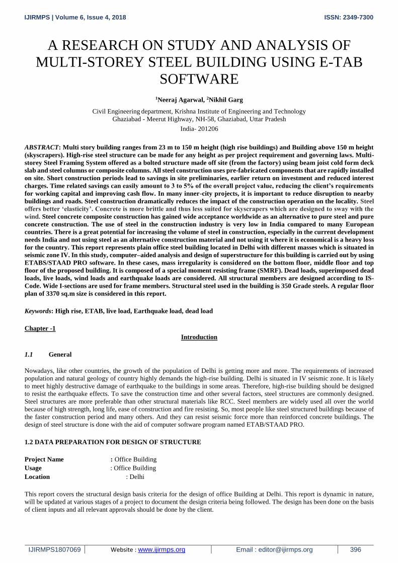
Figure 1.1 Typical Floor Plan of Building
1.3Description of Project:
A high-rise steel building is proposed to be constructed in composite Steel frame structure using fabricated section with yield
strength of plate 300N/mm2.
1.4Design lateral Loads
1.4.1 Seismic Loads
The seismic load is calculated as per IS1893-Part1 – 2002, using the input parameters as provided below
Zone factor (Z) = 0.24
Importance Factor (I) = 1.2
Response Reduction Factor (R) = 5
1.5 Load Combinations
For design of the structure all possible load combinations shall be checked for getting the highest possible stresses in members. The
factor of safety on various load combinations is used as per Indian code for limit state design. The minimum mandatory load
combinations as per guidelines of design codes are listed below for limit state design
1.5 DL +1.5 LL
1.5 DL ±1.5 EQ or WL
1.2 DL +1.2 LL ±1.2 EQ or WL
0.9 DL ± 1.5 EQ or WL
While considering the effect of EQ / WL, the load is applied from all four principal directions and load combinations accordingly
used in the analysis
To check the deflections and drift service load combinations are used as mentioned below
1 DL + 1 LL
1 DL +1 LL ±1 EQ or WL
The various load combination used in the analysis is defined in ETABS Model.
1.6 Structure modeling & Computer Programs
3-D Analysis of all the building structures is being done using ETABS, for gravity and lateral loads. The design of columns and
beams is done using ETABS for all possible load combinations and governing design for the critical load is adopted for
reinforcement detailing. Analysis and design of foundation systems are being carried out using SAFE. The slabis being designed
manually using excel sheet.
Computer Programs used for Engineering Calculations
ETABS
AUTOCAD
MS EXCEL
Chapter-2
Feasibility
1. Steel has the highest strength to weight ratio of any construction material, so it can provide large spans, more space with smaller
size sections compared to concrete.
2. Steel provides a better cycle which enhances the schedule compared to concrete.
3. Steel materials available with no shortage despite the huge demand especially in the lastfew years also the steel construction is
depending only on one type of raw material compared to RC which needs to source different types (cement, steel bars, sand,
aggregates, etc.).
4. Steel is an eco-friendly building material.
IJIRMPS | Volume 6, Issue 4, 2018 ISSN: 2349-7300
IJIRMPS1807069 Website : www.ijirmps.org Email : [email protected] 398
5. Prefabricated Steel units have an advantage over RCC.
6. Easy installation of steel made it preferable over the other mode and material of construction.
7. Due to rapid increase in population, the growth of construction in horizontal land is restricted in mega cities so it is necessary to
move in vertical direction in form of multi-storey building.
Chapter 4
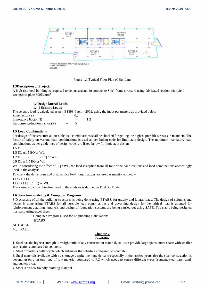
Manual Calculations for Design of Columns
Figure.4.1 Column Numbering
For Column C11
Area of Grid = 3.35×3 = 10.05 m2
Load on Column = 362 KN
Area Required = 362000 ÷ 280 =1290 mm2
Provided Square Section of (95*95) mm2
Check
Sectional Area = 2136 mm2
Rmin =36.41 mm
Slenderness Ratio =82.4
Fcc =290.5 N/mm2 where, fcc= (3.14^2*2*10^5)/ (slenderness ratio) ^2
Allowable Compressive Stress = (0.6*fcc*steel grade)/ ((steel grade^1.4+fcc^1.4) ^ (1/1.4)) = 170.73 KN/m2
Allowable Compressive Load =364.69 KN
For Column C12, C13, C14, C15, C16, C17 and C18
Area of Grid = 5.4*3 =16.2 m2
Load on Column = 583.2 KN
Area required = 2080 mm2
Provided Square Section of (120*120) mm2
Check
Sectional Area = 2736 mm2
Rmin =46.6 mm
Slenderness Ratio =64.4
Fcc =475.8 N/mm2
Allowable Compressive Stress = 218.99 KN/m2
Allowable Compressive Load =599.17 KN
Chapter 5
Earthquake & its consequences on structure
An earthquake is the shaking of the surface of the Earth, resulting from the sudden release of energy in the Earth’s lithosphere that
Create seismic waves.
IJIRMPS | Volume 6, Issue 4, 2018 ISSN: 2349-7300
IJIRMPS1807069 Website : www.ijirmps.org Email : [email protected] 399
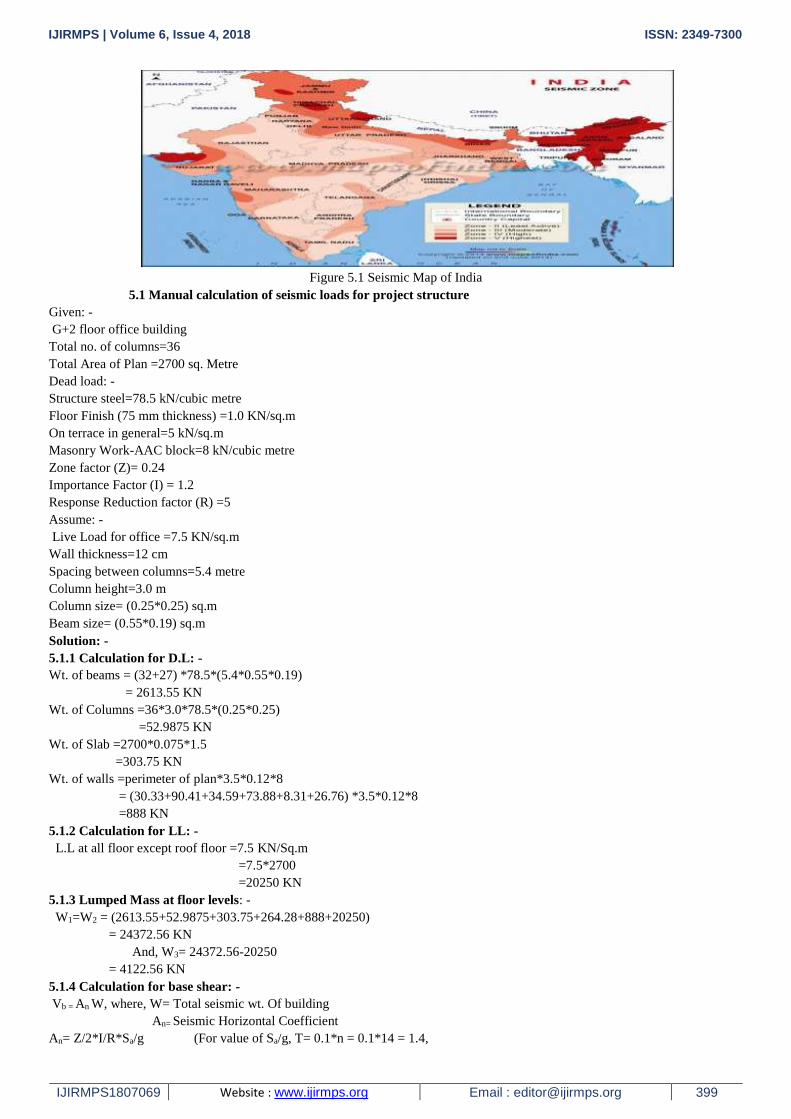
Figure 5.1 Seismic Map of India
5.1 Manual calculation of seismic loads for project structure
Given: -
G+2 floor office building
Total no. of columns=36
Total Area of Plan =2700 sq. Metre
Dead load: -
Structure steel=78.5 kN/cubic metre
Floor Finish (75 mm thickness) =1.0 KN/sq.m
On terrace in general=5 kN/sq.m
Masonry Work-AAC block=8 kN/cubic metre
Zone factor (Z)= 0.24
Importance Factor (I) = 1.2
Response Reduction factor (R) =5
Assume: -
Live Load for office =7.5 KN/sq.m
Wall thickness=12 cm
Spacing between columns=5.4 metre
Column height=3.0 m
Column size= (0.25*0.25) sq.m
Beam size= (0.55*0.19) sq.m
Solution: -
5.1.1 Calculation for D.L: -
Wt. of beams = (32+27) *78.5*(5.4*0.55*0.19)
= 2613.55 KN
Wt. of Columns =36*3.0*78.5*(0.25*0.25)
=52.9875 KN
Wt. of Slab =2700*0.075*1.5
=303.75 KN
Wt. of walls =perimeter of plan*3.5*0.12*8
= (30.33+90.41+34.59+73.88+8.31+26.76) *3.5*0.12*8
=888 KN
5.1.2 Calculation for LL: -
L.L at all floor except roof floor =7.5 KN/Sq.m
=7.5*2700
=20250 KN
5.1.3 Lumped Mass at floor levels: -
W1=W2 = (2613.55+52.9875+303.75+264.28+888+20250)
= 24372.56 KN
And, W3= 24372.56-20250
= 4122.56 KN
5.1.4 Calculation for base shear: -
Vb = An W, where, W= Total seismic wt. Of building
An= Seismic Horizontal Coefficient
An= Z/2*I/R*Sa/g (For value of Sa/g, T= 0.1*n = 0.1*14 = 1.4,
IJIRMPS | Volume 6, Issue 4, 2018 ISSN: 2349-7300
IJIRMPS1807069 Website : www.ijirmps.org Email : [email protected] 400
So, Sa/g= 2.5)
=0.24/2*1/5*2.50
= 0.06
So,
Total Seismic Wt. Of building (W) = (2*24372.56) + 4122.56
= 52867.68 KN
Therefore,
Vb= 52867.68 *0.06
= 3172.06 KN
5.1.5 Distribution of Lateral Seismic Force: -
Storey level Wi (KN) hi (m) Wihi2
(KN-m2)
Qi vi
3 4122.56 9 333927.36 740.36 740.36
2 24372.56 6 877412.16 1945.35 2685.71
1 24372.56 3 219353.04 486.34 3172.05
∑Wihi2=1430692.56
Table-5.1 Calculations of lateral seismic forces
So, these are the values of horizontal shear force at different floor levels, hence the structure should be designed for these
respective values of horizontal shear force.
Chapter -6
Manual Calculations of Slab Designed
6.1 Depth of slab: -
Span
d = 26 × M.F
Assume Percentage steel = 0.3 %
So, M.F = 1.5 2700
d = 26 × 1.5
d = 69.23 m
d ≅ 70 m
Assume cover of 15m and 8mm dia. Bar,
So, D = d + ɸ
2 + cover
= 70 + 4 + 15
= 90 mm
Le = L + d
Or
Le = L + b
(Whichever is less)
So,
Le = 2700 + 70
Or
Le = 2700 + 230
So, Le = 2770 mm or 2.77 m
6.2 Ultimate Load: -
Dead load = 4.75 KN/m
Live Load = 4 KN/m
W = 8.75 KN/m
Wu = 13.125 KN/m
IJIRMPS | Volume 6, Issue 4, 2018 ISSN: 2349-7300
IJIRMPS1807069 Website : www.ijirmps.org Email : [email protected] 401
6.3Factored Bending Moment: -
Mu = WuL2 / 8
=13.125 ×2.77×2.77
8
= 12.588 KN.m
Required Depth: -
d = √Mu
0.138 fck b
2
d = √12.588 ×1000000
0.138 ×20 ×1000
2
d = 67.53 m <dprovided (OK)
6.4 Main Reinforcement: -
Ast = 0.5 fck
fy[1 − √1 −
4.6 Mu
fck ×b×d×d
2] d
Ast = 173.66 mm2
≅ 180 mm2
6.5 Minimum Steel: -
Ast min = 0.12
100× 1000 × 90
= 108 mm2
OK.
So, Provide 8 mm dia. bars.
6.6 Spacing: -
S = 1000 Aɸ / Ast
= (1000 × 50.24) /180
= 279.3
= 280 mm
6.7 Distribution Steel: -
Ast = 108 mm2
Spacing, S = (1000 × 50.27 ) /108
= 465.46 ≥ 5d
= 350 mm
6.8 Check for deflection: -
Ast Provided = 1000 Aɸ / S
= 1000 ×50.27
280
= 180 mm2
Ast Req. = 173.8 mm2,
Fs= 0.58 fyAst req
Ast provided
= 0.58 × 415 ×173.8
180
= 232.4 N/mm2
(Page 38 IS 456: 2000)
% pt Provided = 100 Astp / (bd)
= 100 ×180
1000 ×70
= 0.257
So, for pt. % = 0.257, fs = 232.5
M.F = 2.40
Hence, Actual deflection = Span / d
= 2700 / 70
= 38 mm
Permissible Deflection = B.V × M. f
= 20 × 2.48
= 48 mm
So, Actual deflection <Permissible Deflection
IJIRMPS | Volume 6, Issue 4, 2018 ISSN: 2349-7300
IJIRMPS1807069 Website : www.ijirmps.org Email : [email protected] 402
Chapter -7
Manual Calculation for Design of Beam
7.1 Design
Flange Width provided by Slab = 270 cm
Thickness of Slab= 10 cm
Span of Beam = 5.4 cm
Total Load = 13×5.4×100
= 7020 kg/m
Compressive Force(c) = 70 kg/cm3
Tensile Force = 1400 kg/cm3
Modular Ratio = 2800
3×c
= 13.33
Maximum Bending Moment (M) = 7020×5.4×5.4×100
8
Section Modulus (Z) = M
1400
=1827.707 cm3
Let us try ISMB 550 with cover plate 120×25 mm
Area of Steel = Joist + Plate
= 132.11 + 12×2.5
= 162.11 cm2
Area of Slab = 270×10
= 2700 cm2
Yt = 132.11×27.5+12×2.5×56.25
162.11
Yb = 57.5 – 32.82
= 24.67
Is = Moment of inertia of steel section about its own neutral Axis
Is = 64893.6 + 132.11(32.82- 27.5) + 12×2.5 ×2.5 ×2.5
12 + 12 ×2.5 (24.67 – 1.25)2
= 85103.147 cm4
IC = Moment of inertia of concrete
= 270 ×1000
12
= 22500 cm4
Ycs = Distance between C.G of Concrete and C.G of steel
= As + 1
m × As
= 162.11 + 2700
13
= 369.8 cm2
Yo = Distance of C.G of concrete from Neutral Axis of Compression Section
= Ycs ×As
Asc
IJIRMPS | Volume 6, Issue 4, 2018 ISSN: 2349-7300
IJIRMPS1807069 Website : www.ijirmps.org Email : [email protected] 403
= 162.11 ×37.82
369.8
16.57 cm
Yc = Distance between N.A of Compression Section and C.G of Steel Section = ycs - yo
= 37.82 – 16.57
= 21.24 cm
Ics = Moment of inertia of equivalent section about N.A of compression section
= Is + Ic
m + As × yc × ycs
= 85103.147 + 22500
13 + 162.110 × 21.24 × 37.82
= 217056.36 cm4
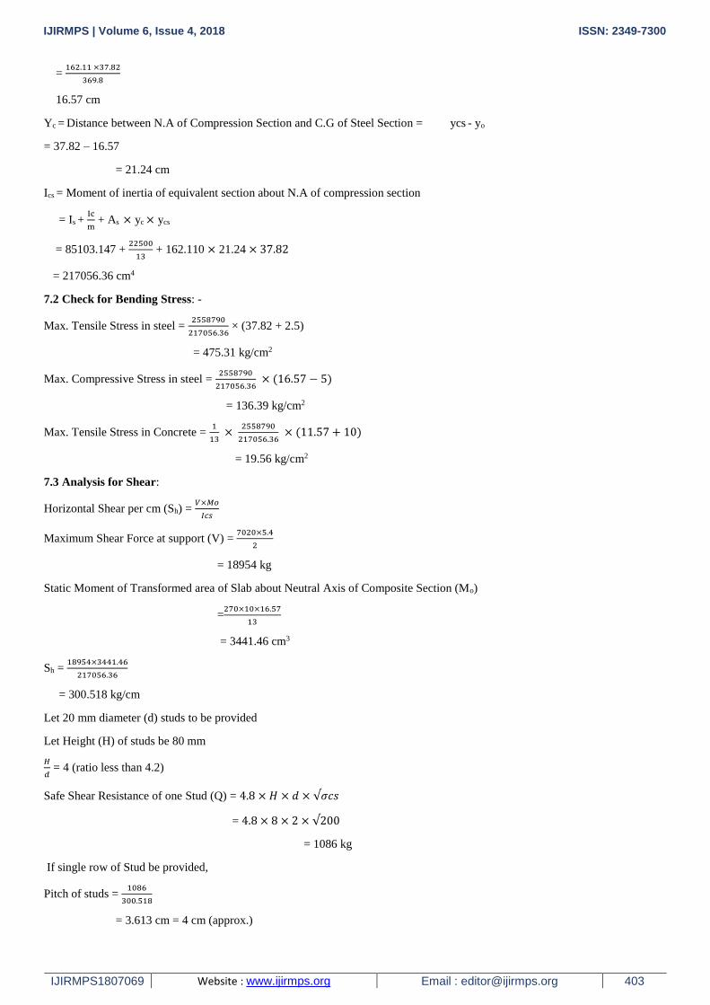
7.2 Check for Bending Stress: -
Max. Tensile Stress in steel = 2558790
217056.36 × (37.82 + 2.5)
= 475.31 kg/cm2
Max. Compressive Stress in steel = 2558790
217056.36 × (16.57 − 5)
= 136.39 kg/cm2
Max. Tensile Stress in Concrete = 1
13 ×
2558790
217056.36 × (11.57 + 10)
= 19.56 kg/cm2
7.3 Analysis for Shear:
Horizontal Shear per cm (Sh) = 𝑉×𝑀𝑜
𝐼𝑐𝑠
Maximum Shear Force at support (V) = 7020×5.4
2
= 18954 kg
Static Moment of Transformed area of Slab about Neutral Axis of Composite Section (Mo)
=270×10×16.57
13
= 3441.46 cm3
Sh = 18954×3441.46
217056.36
= 300.518 kg/cm
Let 20 mm diameter (d) studs to be provided
Let Height (H) of studs be 80 mm
𝐻
𝑑 = 4 (ratio less than 4.2)
Safe Shear Resistance of one Stud (Q) = 4.8 × 𝐻 × 𝑑 × √𝜎𝑐𝑠
= 4.8 × 8 × 2 × √200
= 1086 kg
If single row of Stud be provided,
Pitch of studs = 1086
300.518
= 3.613 cm = 4 cm (approx.)
IJIRMPS | Volume 6, Issue 4, 2018 ISSN: 2349-7300
IJIRMPS1807069 Website : www.ijirmps.org Email : [email protected] 404
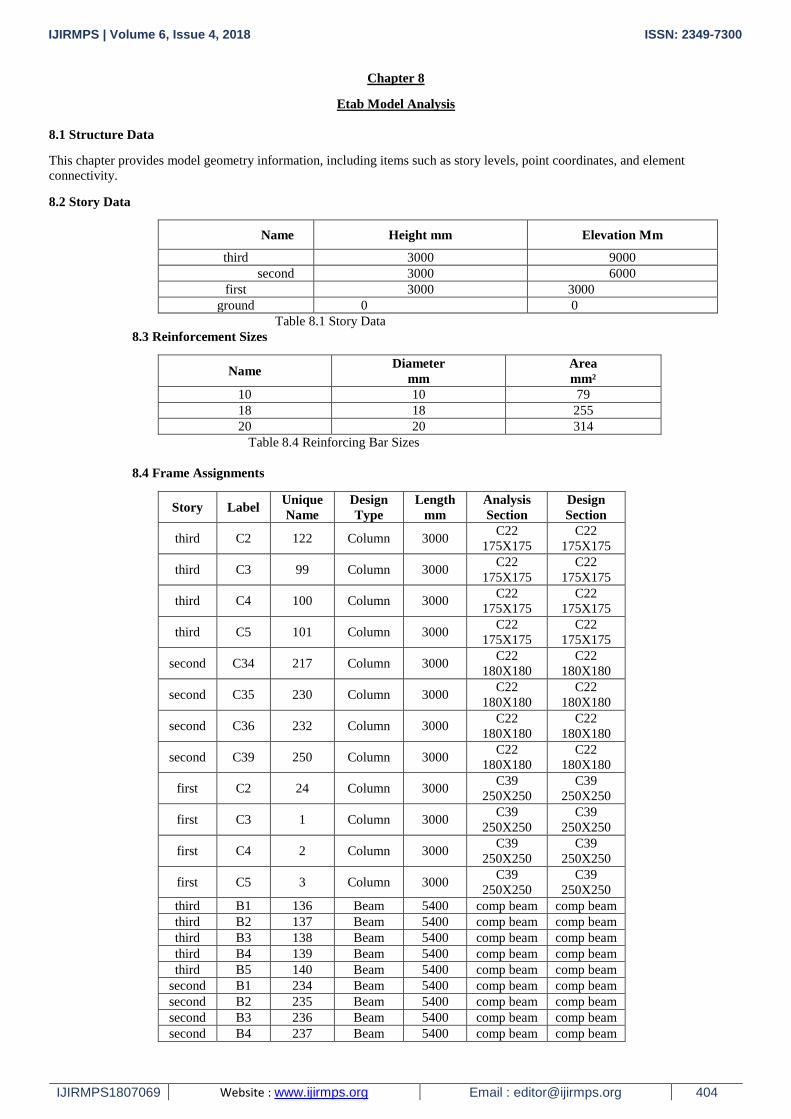
Chapter 8
Etab Model Analysis
8.1 Structure Data
This chapter provides model geometry information, including items such as story levels, point coordinates, and element
connectivity.
8.2 Story Data
Name Height mm Elevation Mm
third 3000 9000
second 3000 6000
first 3000 3000
ground 0 0
Table 8.1 Story Data
8.3 Reinforcement Sizes
Name Diameter
mm
Area
mm²
10 10 79
18 18 255
20 20 314
Table 8.4 Reinforcing Bar Sizes
8.4 Frame Assignments
Story Label Unique
Name
Design
Type
Length
mm
Analysis
Section
Design
Section
third C2 122 Column 3000 C22
175X175
C22
175X175
third C3 99 Column 3000 C22
175X175
C22
175X175
third C4 100 Column 3000 C22
175X175
C22
175X175
third C5 101 Column 3000 C22
175X175
C22
175X175
second C34 217 Column 3000 C22
180X180
C22
180X180
second C35 230 Column 3000 C22
180X180
C22
180X180
second C36 232 Column 3000 C22
180X180
C22
180X180
second C39 250 Column 3000 C22
180X180
C22
180X180
first C2 24 Column 3000 C39
250X250
C39
250X250
first C3 1 Column 3000 C39
250X250
C39
250X250
first C4 2 Column 3000 C39
250X250
C39
250X250
first C5 3 Column 3000 C39
250X250
C39
250X250
third B1 136 Beam 5400 comp beam comp beam
third B2 137 Beam 5400 comp beam comp beam
third B3 138 Beam 5400 comp beam comp beam
third B4 139 Beam 5400 comp beam comp beam
third B5 140 Beam 5400 comp beam comp beam
second B1 234 Beam 5400 comp beam comp beam
second B2 235 Beam 5400 comp beam comp beam
second B3 236 Beam 5400 comp beam comp beam
second B4 237 Beam 5400 comp beam comp beam
IJIRMPS | Volume 6, Issue 4, 2018 ISSN: 2349-7300
IJIRMPS1807069 Website : www.ijirmps.org Email : [email protected] 405
second B5 238 Beam 5400 comp beam comp beam
first B1 38 Beam 5400 comp beam comp beam
first B2 39 Beam 5400 comp beam comp beam
first B3 40 Beam 5400 comp beam comp beam
first B4 41 Beam 5400 comp beam comp beam
first B5 42 Beam 5400 comp beam comp beam
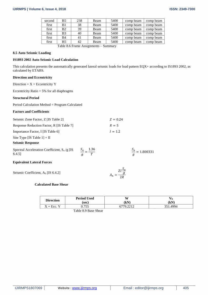
Table 8.6 Frame Assignments – Summary
8.5 Auto Seismic Loading
IS1893 2002 Auto Seismic Load Calculation
This calculation presents the automatically generated lateral seismic loads for load pattern EQX+ according to IS1893 2002, as
calculated by ETABS.
Direction and Eccentricity
Direction = X + Eccentricity Y
Eccentricity Ratio = 5% for all diaphragms
Structural Period
Period Calculation Method = Program Calculated
Factors and Coefficients
Seismic Zone Factor, Z [IS Table 2] 𝑍 = 0.24
Response Reduction Factor, R [IS Table 7] 𝑅 = 5
Importance Factor, I [IS Table 6] 𝐼 = 1.2
Site Type [IS Table 1] = II
Seismic Response
Spectral Acceleration Coefficient, Sa /g [IS
6.4.5]
𝑆𝑎
𝑔=
1.36
𝑇
𝑆𝑎
𝑔= 1.800331
Equivalent Lateral Forces
Seismic Coefficient, Ah [IS 6.4.2] 𝐴ℎ =
𝑍𝐼𝑆𝑎
𝑔
2𝑅
Calculated Base Shear
Direction Period Used
(sec)
W
(kN)
Vb
(kN)
X + Ecc. Y 0.755 6779.2212 351.4994
Table 8.9 Base Shear
IJIRMPS | Volume 6, Issue 4, 2018 ISSN: 2349-7300
IJIRMPS1807069 Website : www.ijirmps.org Email : [email protected] 406
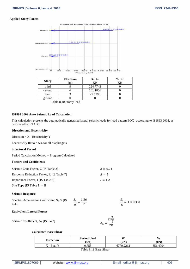
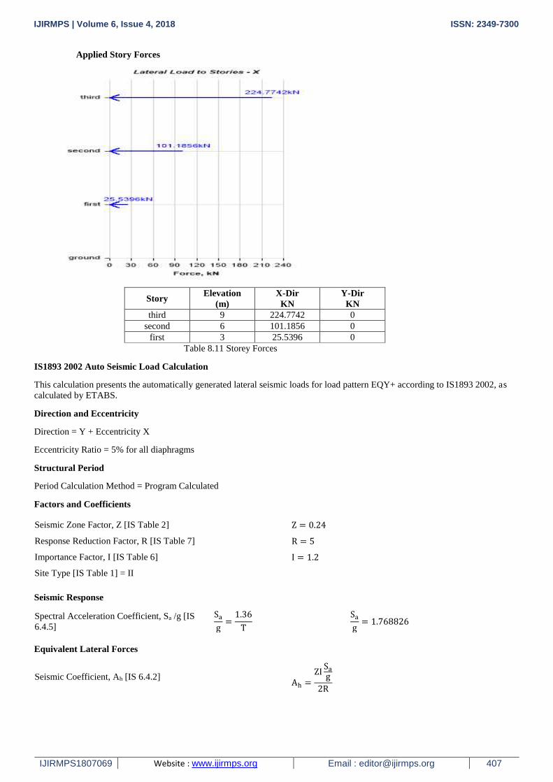
Applied Story Forces
Story Elevation
(m)
X-Dir
KN
Y-Dir
KN
third 9 224.7742 0
second 6 101.1856 0
first 3 25.5396 0
ground 0 0 0
Table 8.10 Storey load
IS1893 2002 Auto Seismic Load Calculation
This calculation presents the automatically generated lateral seismic loads for load pattern EQX- according to IS1893 2002, as
calculated by ETABS.
Direction and Eccentricity
Direction = X - Eccentricity Y
Eccentricity Ratio = 5% for all diaphragms
Structural Period
Period Calculation Method = Program Calculated
Factors and Coefficients
Seismic Zone Factor, Z [IS Table 2] 𝑍 = 0.24
Response Reduction Factor, R [IS Table 7] 𝑅 = 5
Importance Factor, I [IS Table 6] 𝐼 = 1.2
Site Type [IS Table 1] = II
Seismic Response
Spectral Acceleration Coefficient, Sa /g [IS
6.4.5]
𝑆𝑎
𝑔=
1.36
T
Sa
g= 1.800331
Equivalent Lateral Forces
Seismic Coefficient, Ah [IS 6.4.2] Ah =
ZISa
g
2R
Calculated Base Shear
Direction Period Used
(sec)
W
(kN)
Vb
(kN)
X - Ecc. Y 0.755 6779.2212 351.4994
Table 8.11 Base Shear
IJIRMPS | Volume 6, Issue 4, 2018 ISSN: 2349-7300
IJIRMPS1807069 Website : www.ijirmps.org Email : [email protected] 407
Applied Story Forces
Story Elevation
(m)
X-Dir
KN
Y-Dir
KN
third 9 224.7742 0
second 6 101.1856 0
first 3 25.5396 0
Table 8.11 Storey Forces
IS1893 2002 Auto Seismic Load Calculation
This calculation presents the automatically generated lateral seismic loads for load pattern EQY+ according to IS1893 2002, as
calculated by ETABS.
Direction and Eccentricity
Direction = Y + Eccentricity X
Eccentricity Ratio = 5% for all diaphragms
Structural Period
Period Calculation Method = Program Calculated
Factors and Coefficients
Seismic Zone Factor, Z [IS Table 2] Z = 0.24
Response Reduction Factor, R [IS Table 7] R = 5
Importance Factor, I [IS Table 6] I = 1.2
Site Type [IS Table 1] = II
Seismic Response
Spectral Acceleration Coefficient, Sa /g [IS
6.4.5]
Sa
g=
1.36
T
Sa
g= 1.768826
Equivalent Lateral Forces
Seismic Coefficient, Ah [IS 6.4.2] Ah =
ZISa
g
2R
IJIRMPS | Volume 6, Issue 4, 2018 ISSN: 2349-7300
IJIRMPS1807069 Website : www.ijirmps.org Email : [email protected] 408
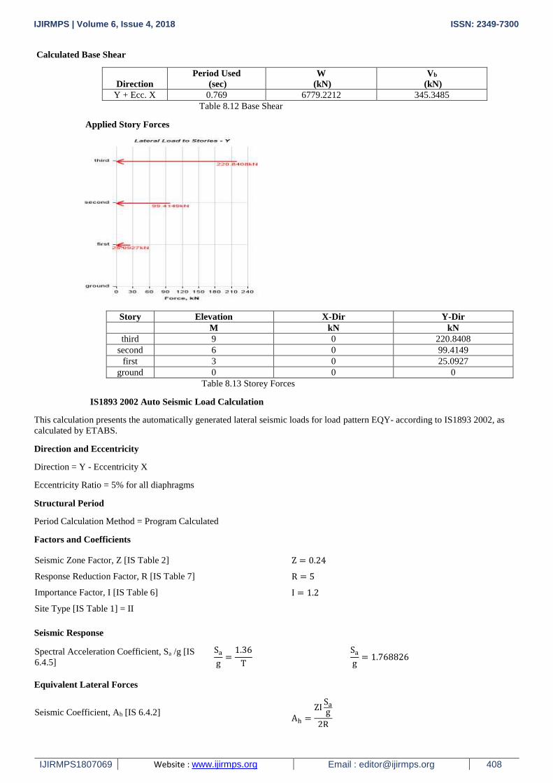
Calculated Base Shear
Direction
Period Used
(sec)
W
(kN)
Vb
(kN)
Y + Ecc. X 0.769 6779.2212 345.3485
Table 8.12 Base Shear
Applied Story Forces
Story Elevation X-Dir Y-Dir
M kN kN
third 9 0 220.8408
second 6 0 99.4149
first 3 0 25.0927
ground 0 0 0
Table 8.13 Storey Forces
IS1893 2002 Auto Seismic Load Calculation
This calculation presents the automatically generated lateral seismic loads for load pattern EQY- according to IS1893 2002, as
calculated by ETABS.
Direction and Eccentricity
Direction = Y - Eccentricity X
Eccentricity Ratio = 5% for all diaphragms
Structural Period
Period Calculation Method = Program Calculated
Factors and Coefficients
Seismic Zone Factor, Z [IS Table 2] Z = 0.24
Response Reduction Factor, R [IS Table 7] R = 5
Importance Factor, I [IS Table 6] I = 1.2
Site Type [IS Table 1] = II
Seismic Response
Spectral Acceleration Coefficient, Sa /g [IS
6.4.5]
Sa
g=
1.36
T
Sa
g= 1.768826
Equivalent Lateral Forces
Seismic Coefficient, Ah [IS 6.4.2] Ah =
ZISa
g
2R
IJIRMPS | Volume 6, Issue 4, 2018 ISSN: 2349-7300
IJIRMPS1807069 Website : www.ijirmps.org Email : [email protected] 409
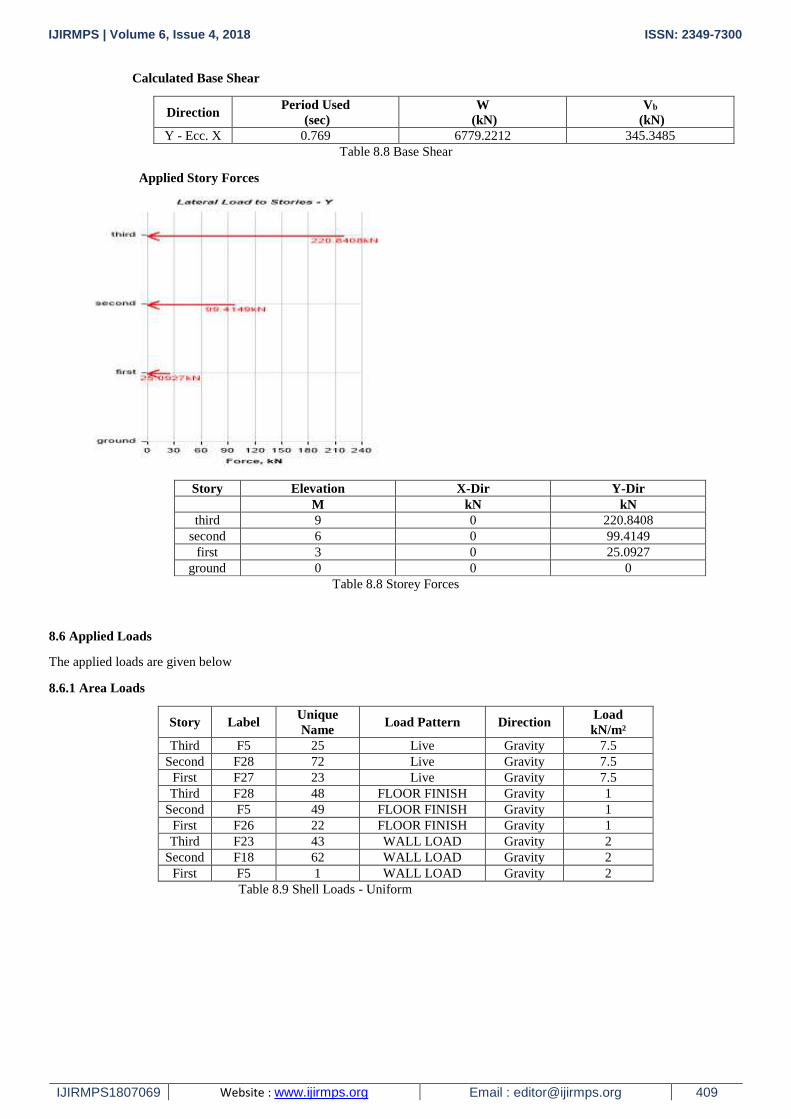
Calculated Base Shear
Direction Period Used
(sec)
W
(kN)
Vb
(kN)
Y - Ecc. X 0.769 6779.2212 345.3485
Table 8.8 Base Shear
Applied Story Forces
Story Elevation X-Dir Y-Dir
M kN kN
third 9 0 220.8408
second 6 0 99.4149
first 3 0 25.0927
ground 0 0 0
Table 8.8 Storey Forces
8.6 Applied Loads
The applied loads are given below
8.6.1 Area Loads
Story Label Unique
Name Load Pattern Direction
Load
kN/m²
Third F5 25 Live Gravity 7.5
Second F28 72 Live Gravity 7.5
First F27 23 Live Gravity 7.5
Third F28 48 FLOOR FINISH Gravity 1
Second F5 49 FLOOR FINISH Gravity 1
First F26 22 FLOOR FINISH Gravity 1
Third F23 43 WALL LOAD Gravity 2
Second F18 62 WALL LOAD Gravity 2
First F5 1 WALL LOAD Gravity 2
Table 8.9 Shell Loads - Uniform
IJIRMPS | Volume 6, Issue 4, 2018 ISSN: 2349-7300
IJIRMPS1807069 Website : www.ijirmps.org Email : [email protected] 410
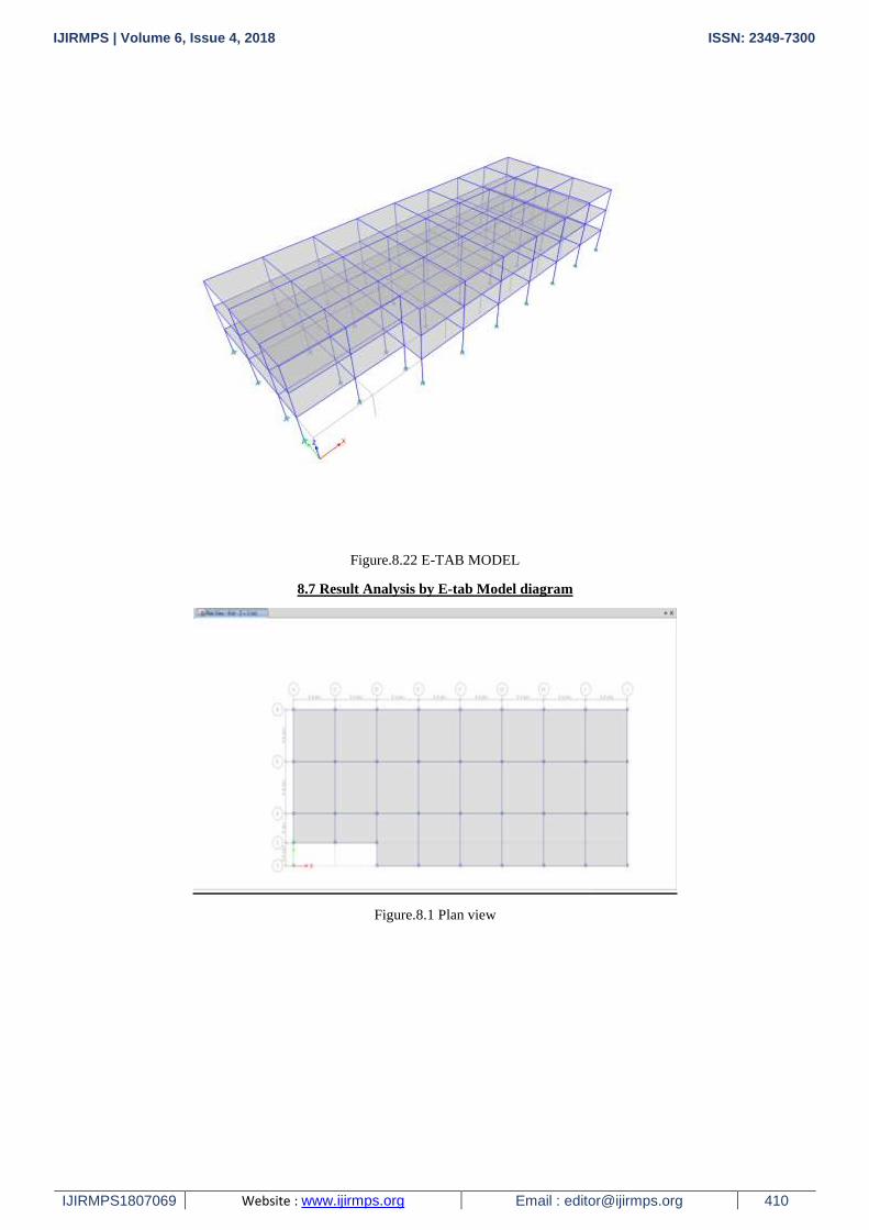
Figure.8.22 E-TAB MODEL
8.7 Result Analysis by E-tab Model diagram
Figure.8.1 Plan view
IJIRMPS | Volume 6, Issue 4, 2018 ISSN: 2349-7300
IJIRMPS1807069 Website : www.ijirmps.org Email : [email protected] 411
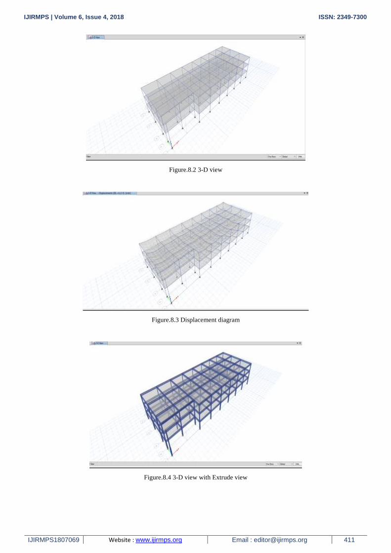
Figure.8.2 3-D view
Figure.8.3 Displacement diagram
Figure.8.4 3-D view with Extrude view
IJIRMPS | Volume 6, Issue 4, 2018 ISSN: 2349-7300
IJIRMPS1807069 Website : www.ijirmps.org Email : [email protected] 412
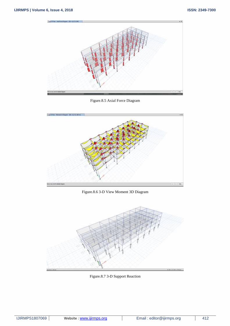
Figure.8.5 Axial Force Diagram
Figure.8.6 3-D View Moment 3D Diagram
Figure.8.7 3-D Support Reaction
IJIRMPS | Volume 6, Issue 4, 2018 ISSN: 2349-7300
IJIRMPS1807069 Website : www.ijirmps.org Email : [email protected] 413
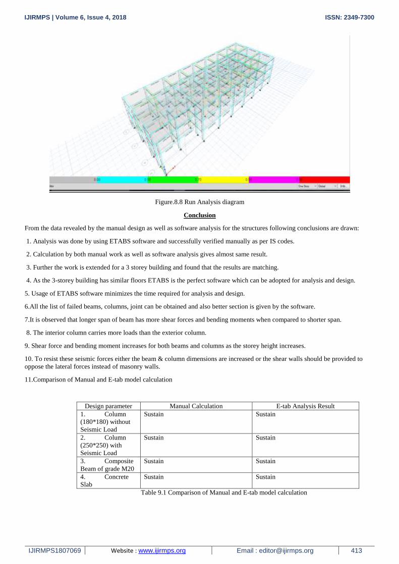
Figure.8.8 Run Analysis diagram
Conclusion
From the data revealed by the manual design as well as software analysis for the structures following conclusions are drawn:
1. Analysis was done by using ETABS software and successfully verified manually as per IS codes.
2. Calculation by both manual work as well as software analysis gives almost same result.
3. Further the work is extended for a 3 storey building and found that the results are matching.
4. As the 3-storey building has similar floors ETABS is the perfect software which can be adopted for analysis and design.
5. Usage of ETABS software minimizes the time required for analysis and design.
6.All the list of failed beams, columns, joint can be obtained and also better section is given by the software.
7.It is observed that longer span of beam has more shear forces and bending moments when compared to shorter span.
8. The interior column carries more loads than the exterior column.
9. Shear force and bending moment increases for both beams and columns as the storey height increases.
10. To resist these seismic forces either the beam & column dimensions are increased or the shear walls should be provided to
oppose the lateral forces instead of masonry walls.
11.Comparison of Manual and E-tab model calculation
Design parameter Manual Calculation E-tab Analysis Result
1. Column
(180*180) without
Seismic Load
Sustain Sustain
2. Column
(250*250) with
Seismic Load
Sustain Sustain
3. Composite
Beam of grade M20
Sustain Sustain
4. Concrete
Slab
Sustain Sustain
Table 9.1 Comparison of Manual and E-tab model calculation
IJIRMPS | Volume 6, Issue 4, 2018 ISSN: 2349-7300
IJIRMPS1807069 Website : www.ijirmps.org Email : [email protected] 414
References
1. Ramumrutham, theory of structure
2. B.C Punamina, theory of structure
3. B.C Punamia, Reinforced concrete structure
4. Ragy Jose, Restina Mathew, Sandra Devan, Sankeerthana Venu,and Mohith Y S5,” ANALYSIS AND DESIGN OF
COMMERCIAL BUILDING USING ETABS”, International Research Journal of Engineering and Technology, e-ISSN: 2395 -
0056, Volume: 04 Issue: 06 | June-2017,page no.625-630.
5. Abhay Guleria, “Structural analysis of a multi-storeyed building using ETABS for different plan configurations”, International
Journal of Engineering Research and Technology, ISSN: 2278-0181, Vol. 3 Issue 5, May 2014.
6. Puneet mittal and Nishant Kad, “A comparison of the analysis and design results of 4 storey using STAAD Pro and ETABS
software”, International Journal of Research, Vol. 3 Issue 5, March 2016
7. Structural Analysis of a Multi-Storeyed Building using ETABS for different Plan Configurations, International Journal of
Engineering Research & Technology (IJERT), ISSN: 2278-0181, Vol. 3 Issue 5, May – 2014.
IS-Code Books
IS: 875 (Part-2)-1987: - Code of Practice for Design Loads (Other than Earthquake) for Building
and Structures-Dead loads
IS: 875 (Part-2)-1987: - Code of Practice for Design Loads (Other than Earthquake) for Building
and Structures-Imposed loads
IS: 456 -2000: - Code of Practice for Plain and Reinforced Concrete.
IS: 1893 (Part-1)-2002: - Indian Standard Criteria for Earthquake
Resistant Design of Structures
IS 800-2007: - General Construction in Steel – Code of Practice.
SP 6 part 1 For design of column