Embed Size (px)
Citation preview

Instructions for use
Title A Review of Anisotropic Polar Ice Models : from Crystal to Ice-Sheet Flow Models
Author(s) Gagliardini, Olivier; Gillel-Chaulet, Fabien; Montagnat, Maurine
Issue Date 2009-12
Doc URL http://hdl.handle.net/2115/45447
Type bulletin (article)
Note II. Ice-sheet flow model
File Information LTS68suppl_014.pdf
Hokkaido University Collection of Scholarly and Academic Papers : HUSCAP
A Review of Anisotropic Polar lee Models: from Crystal to Ice-Sheet Flow Models
Olivier Gagliardini, Fabien Gi llel-Chau1ct, Maurine Mo ntagna!
LGGE CNRS/ UlP-Grelloble I. BP 96, F-38402 Saillf-Man ill d' Heres Cede.\". France. [email protected]
Abstract: The icc single crystal is onc of the most anisotropic natural materi als and the resulting viscous behaviour o f polycrystalline ice can also be strongly anisotropic and is a fu nction o f the distribution of the cryslal c-axis orientations, i.e. ils fa bric. Such a strong and s trai n-dependant an isotropy o f the icc pol ycryslaJ ccnai nly affects the general flow of polar ice. The aim of this paper is to present an exhausti ve overview of most of the glaciological efforts mndc from morc than two decades to account for pol <l f icc <l nisotropy in ice now mode lling , from the crystal to the icc-sheets seale. Wc firs t reeall the deformation and recrystallization proccsses occurr ing withi n icc-sheets and their respective effect on the polar icc textures. Then. the different models developed to describe the behaviour of the ice crystal and the polycrystal are presentcd, with a speci al emphasis on homogenization methods and fabric descript ion. Finally, ex isting anisotropic ice now models and their applications are reviewed.
Key words : Anisotropic model, Crystal , Fabric, Polycrystal, lee
Introduction
The ice single cryst31 is onc o f the most 3tlisotropic natur31 matcrials. Thi s s trong 3nisotropy results cssenti:llly fro m di slOC:lti on gl ide on the b:ls:ll pl ane, perpendicul ar 10 the crystal hexagonal symmetry ax is, c:l lled the c-axis. During the gravity driven now of ice with in an icc-sheet, the polycrystal develops a strain-induced fabric, that is, a preferred orientation o f the c-axes of its grai ns. Near the surface, polycrystalline icc results from the tmnsformation of deposited snow, and since the ice crystals are di stributed at random, its mechanical behaviour is isotropic. Observations o f deep icc cores drilled in Antarctica and Greenl and have shown very di fferent fabric patterns within the ice-shcet, corresponding 10 different now condit ions. Strain-induced fabric, combined with the s trong ani sotropy o f the crystal, result in a strong fabric-dependent anisotropy o f the polycrystalline
I AtM) called dynamic discontinuous recry,ta llizat ion.
ice. As shown experimentall y by Pimienta and others [78]. a polycrystal of ice with all the c-axcs of its grains orientated in the same direction deforms ten times faster than an equi valent isotropic sample, whe n it is sheared parallclto the basal pl anes.
The spatial vari ability of the observed fabrics. from sing le max imum fabrics l23 , 88]10 girdle type fabrics [58], ind icates the strong coupling ex isting between the fabric and the local now conditions. At some stage. it is a chance. because ice-shects can be secn as a huge database contai ning fabric evolution experimcnts for a very large range o f stra in-history and te mperature conditions. On the reverse, the very small amount of data (few icc cores) rcgarding the icc-sheets typical size renders the expl oitation of all these data very d ifficult. Moreover, the very small s train-rates and very low temperatures prevail ing inside an ice-sheet are quasi- imposs ible 10 be reproduced by cold-room experiments of fabric evolution. All these together clearly ind icate that a strong modelling effort is needed in order to analyse the measured fabrics at a particulardrilling site. Due to the complex coupl ing between the anisotropic now and the fabric evolution, thi s modell ing effort sho uld incl ude the coupl ing of both in a local flow model.
Very oft en, ice is assumed to be an isotropic med ium, the behaviour of which foll ows a classical Norton-HolT type law. namely the Glen's law in glaciology. link ing the strain rate b to the deviatoric Cauchy stress 5:
( I )
where 7 2 = t r 52 /2 is the second invariant of the dcviatoric Cauchy stress and Bn is a fl uidity parameter function of the temperature. T he stress exponent entering the G len 's law is found 10 be close 10 3 for laboratory experiments [26], whereas an exponent equal or even smaller th an 2 is certainl y more adapted 10 describe the behaviour of in-situ polycrystall inc icc in the mai n part o f the icc-sheets [ 19, 59. 6 1J. Within an icc-sheet. a stress exponent equal to 3 would be associated with deformation occurring in the bottom part of some cores. whcre the temperature can be higher than - 10 °C and where dynamic migrat ion t recrystallization is assumed to be
-149-
the main softening mechanism.
As far as the polyerystalline iee is textured, the Glen's law docs not hold anymore, and an anisotropic formulation must be adopted to describe properly the polycrystalline anisotropic behaviour. TIle aim of this paper is to present the differcnt classes of anisotropic models used so far in glaciolo£y.
We first reeall the deformation and reerystallization processes of polar ice. Then, the three existing models for the crystal are presented as well as the equations for crystal rotation. The different fabric descriptors are reviewed, and general relation linking these descriptors are given. A special emphasis is given to the comparison of the diflcrent parameterized orientation distribution functions presented in the glaciological1iterature so far. The various classes of anisotropic polycrystal models arc then presented. At last. the existing anisotropic flow models and the results obtaincd from their applications are discussed.
2 Deformation and recrystallization processes of pola r ice
2.1 Defo rma tion mechanisms When an ice core is located at a domc. a fi rst order ap
proximation is to assumc a uniform stcady-state vertical strain-rate ~zz along the core, given by:
~u = b/ H, (2)
where b is the accumulation rate and H is the icc thickness. By taking values from Vostok (Antarctica) icc core, wi th the present accumulation rate of2.3 g cm - 2 a- I, the vertical strain-rate is about 7 x 10- 6 a - I [58[. Lipcnkov and others [58] estimated the horizontal shear strain-rate along Vostok icc core by assuming a flow law with a stress exponent n=3. With a surface slope of 10- 3 , the horizontal shear stress at 2000 m depth is lower than 0.02 MPa, leading to a shear strain-rate of the order of 4 x 10- 6 a- I at the salTle depth.
Although strain-rales and dcvialoric stresses arc very low, it is now commonly accepted that dcfomlation processes along polar iee cores are dominated by the viscoplastic mechanism of dislocation glide mainly along the basal plane. Diffusional creep, commonly associated wi th such condit ions in many materials, yields a viscosity much higher than that deduced from field data l61J. Deformation by basal glide of dislocations is associated with efficient processes of accommodation such as normal grain growth and dynamic recrystall ization which arc described in the next paragraph.
2.2 G rain growth and recrystallization in ice-sheets From texture and microstructure measurements along
polar ice cores, it W~IS evidenced that the evolution of icc structure is mainly associated with deformation pmcesscs but infl uenced by grain growth and recrystalliza-
tion mechanisms [2, 8. 58]. Normal grain growth is dis tinctly observed in the upper layers of the icc sheets (several hundreds of meter) where thc mean grain size is incrcasing with depth. Such a grain growth is driven by the decrease in rree energy related to the reduction in grain boundary area. The gr:tin size is generally larger than 1 mm and the grain boundary free encrgy is 19b = 0.065 J m- 2 [3]. A parabolic growth relationshi p between grain size and time was found along several cores in Greenland and Antarctica [47. 58. 88J.
Below this normal grain growth region, heterogeneous deformation within grains leads 10 localized high internal stresses that can relax through the formation o r subboundaries, by the gathering of dislocations 13]. The misorientation associated with these sub-boundaries is supposed 10 increase with deformation and sub-boundaries to evolve into high-angle boundaries, leading to the creation of new grains (polygonization). Such a mechanism can be associated with grain boundary migration driven by the difference in deformation stored energy between boundaries and is named rotarion or continllOilS recry.~tallil.ario", but also with normal grain growth if the corrcsponding driv ing force remai ns higher (very low strain-rate conditions). Evidences of polygon ization arc givcn by the visual isation of low angle boundaries on icc thin sections, and the measurement of an average constant grain size along cores where temperature and impurity contents remain constant. For the Byrd icc core (Antarctica). Alley and others [4] indicate lhat polygonizalion processes associated with rotation recrystallization counteract further normal grain growth below 400 m dcpth. The same explanation was given [13, 88J for the constant average grai n size measured along the GRIP icc core (Grecnland) between 650 and 1500 m dept h. Along the VoslOk and EPICA Dome C icc cores (Antarctica), due 10 the continuous increase in temperature from the surface, such an interruption in the grain size profile is not observed.
Nevertheless, as shown along the EPICA Dome C ice core by Durand and others [24J. the grain size variations along the main part of the core can only be well reproduced by modelling the effect of normal grain growth and rotation recrystallization, associated with the impact of impurity contents on the grain boundary migration rate. The pinning of grain boundaries by dust (insoluble impurities) explains most of the obscrved modifications of the microstructure. which arc highly visible at the transition betwecn glacial ice and interglacial icc. but rotation recrystallization becomes very active to balance normal grain growth in the rangc 1000 - 1750 m. Below this depth, Durand and others 124J suggest a thermally activated unpinning of grain boundaries from p.!rticies and provide a good estimation of the average grain size evolution up to 2135 m.
More recently. Obbard and othcrs have measured ori-
-150-
entation relations between neighbouring grains in ice from the GISP2 icc core (Green land) [75J and the Vostok icc core [74J, using the electron backscatter difrraction technique. Such a technique provides full c- and a -ax is orientation of individual grains, and then allows to compare nearest-neighbour orientation relationships. Along both cores they measured correlations between adjacent grains that reveal the presence of polygonizat ion associated with rotation recrystallizat ion.
Deeper in some icc cores, very large amplitudes of grai n size variations can be measured, such as below 2780 m along the GRIP core. Such high variations are attribuled to the effect of a tcmperatuTC increase in the core which can become higher than - 10 0c. and favour the occurrence of migration rccrystall ization. This recrystallization process is characterised by a very fa st grain growth , with a boundary velocity that can be 10 times higher than in the normal grain growth regime f27J. Such a recrystallization process is associated with the nueleation of new grai ns through a process that should be elose to the bulging described for geological materials l48J. Migration recrystallization fabrics di f'fer completely from strain-induced fabrics because the new grains are orientatcd favourably for tbe macroscopic dcformation. Gow and Williamson [47[ have reportcd simil ar observations on the lowcr part of the Byrd ice core.
2.3 Fabric development
In pol ar ice, the fabric is measured via the orientation of the grain c-axes [8, 58. 88, 92J. The fabric development as observed along pol ar icc cores is mainly associated with the rotation of grai ns induced by deformation. meaning by intracrystalline glide of dislocat ions, but can be influenced by recrystall ization processes f3. 6, 17J .
In the main par! of the icc core, only normal grai n growth and rotation recrystallization can influencc fabric development. The exaet influence on the c-ax is rotation rate is not elear yet, although the observed fabrics in the corresponding part of the core are generally very elose to what is expected considering the main imposed stra in. Along the EPICA Dome C ice core, the strain is mainly vertical compression, due to the location of the core theoretically at a topographical dome. Such a main strain induces a rotation of the c·axes toward the vertical ax is [21 , 92J. This configurat ion was also observed along the GR IP and the Dome Fuji icc cores [7, 88]. Along the Vostok ice core, the main strai n is horizontal tension , leadi rig the c-axes to orientate in a vertical plane, perpendicular to the tension direction !58J.
Nevertheless. texture observat ions (grain shape ,lI1d orientat ion) reveal some areas where horizontal shear seems to have a noticeable effect [22, 21). Such a shear will induce a sharp change in the texture development, by accelerating the rotation toward the vertical axis. As it will be discussed in the application part of this paper,
such a shear can have a strong impact on icc flow, by inducing a positive feedback in some initially softer layers [2 1[.
Although rOlation recrystallization is on ly supposed to slow down the fabric development induced by the deformation , migration recrystallization induces fabrics which are much differcnt than deformation-induced fabrics. As observed in alpine glaciers [61. 90J. during lab experiments [5 1. 52[ or at the bottom of the GRIP core [88[, the c-axes are rotating toward a direction of easy glide, betwccn 30° and 45° from the vcrtical axis. Such a fabric provides orientations that arc favouring the imposed compression strain . 111e so-formed fabrics arc either imposed by the nueleation of so-ca lled \fell oriented grains, and/or the favoured growth of such grains. They arc. then , controlled by the stress state within the polycrystal L25J. The induced softening of the polycrystal behaviour in the bottom part of the core can have a non-negligible impact on the global flow around the core. and shou ld be accurately takcn into account in modell ing.
3 Models for the ice single crysta l
3. 1 Crystal viscous laws Such models arc rcq uired hy homogenization mod
cis to derive the macroscopic behaviour from the microscopic properties. We present hereafter thc three di ffcrent approaches that can be found in the glac iologica l literature.
3. 1.1 Schmid law
The classical approach in material se ience to describe the viseopl astic behaviour of a crystall ite is the use of the socalled Schmid law, which consist of the sum of all thc slip system contributions f9, II, 12, 13J. To definc thc orientation of all these slip systems, one can introducc the Schmid tensor:
(3)
wherc n 8 and b8 arc the unit vcctors norma l and parallel to the Burgers vector of the slip system s, respectively. For a givcn deviatoric Cauchy stress 5 , the strai n-rate D is obtained as:
{. s r'® r'l r" SI"-'} D = 10L $ --,- :5, $=1 TO TO
(4)
where to is a reference shear rate and the T6 are the refeTCnce resolved shear stresses (RRSS) which control the sti ffness of each slip system. The stress sensiti vity cxponent n can be different for each slip system, but in practise the same value is always adopted. For icc. Castelnau and ot hers [I 11 have numbercd nine independent slip systems arising from the choicc of the thrcc families of
-151-
planes: basal (two independent systems), prismatic (two) and pyramidal (five). Due to the very strong anisotropy of the crystal, the RRSS for the basal plane,$ is expected to be much larger than the prismatic and pyramidal ones (,r and ,t;y, respectively). [n order 10 define the position of the slip systems relative 10 a fixed reference frame, the three Euler angles are needed.
3.1.2 Basal slip system model
Considering that mOSt of \he deformation of a single crystal results from basal glide and noticing that the basal plane is isotropic when n = 1 or n = 3 [53]' many authors have adopted a simple model for the icc crystal assuming only deformation by basal glide [5 , 10, 45, 60, 91]. When expressed in the grain reference frame {9R} defined by e~ = c , th is law simply reads:
D9 _ Wn "- 'S' . I 2 i3 - 2'1> i3 t = , , (5)
where,; = (SY3 'l + S~3'l)/2 , and ·r/Jn is the reference fluidity for basal glide. This simple law considers that all the other non-basal strain-rate components van ish. The main advantilge of this law is its simplicity, and that only one orientation (two angles) is needed in order to orientate the grain relative 10 a fixed reference frame. On the OIher homd, the main drawback of this law is to conductIO zero deformation in some directions for strongly textured polycrystal (one max im um or girdle type fabrics).
3.1.3 Continuous Transversely Isotropic (CTI) model
With the idea of keeping the advantage of a grain orientatcd solely by one unit vcctor, while ameliorating the behaviour description of the previous model , Meyssonnier and Philip [67[ have proposed a continuous transversely isotropic (CTI) law in the particular case of a linear behaviour (n = 1):
0+ 2 + "l/JdJ-- tr(M 3 · S)M f,
41' - 1
(6)
where 1\13 = c ® c is the structure tensor used to describe the axial symmetry around the crystal c axis. The notation OD denotes the symmetric part o f a tensor. The three introduced rheological parameters allow 10 quantify the crystal anisotropy: 1/; , is the basal shear fluidit y, {3 characteri ses the fluidity ratio in and parallel 10 the basal planes. and l' is the tension-compression fluidity ratio in and perpendicular to the basal planes. The strong crystal anisotropy and the condition that the dissipation potential must be positive, lead to the following inequalities: o :::; {3 « 1 and 1/ 4 :s; l' :::::: 1. The extension to the non-linear case (n 1= 1) is not straightforward and has
not been devcloped so far.
One ean show that in the linear case, the Schmid law (4) and thc CTll aw (6) arc fully equivalent, and the rheological parameters of one can be identified from thosc of thc other [66]. Moreover. when considering only basal planes, by setting infinite RRSS in prismatic and pyram idal planes for the Schmid law (4) and {3 = 0 in the CTI law (6), the three presented crystal laws arc equivalents.
3.2 Crystal rotation
The crystal deformation resulting from dislocation glide in the different slip planes induces an evolution of the orientation of thesc planes. For a large part of the icesheet, this rotation induced by deformation is the most important mechanism contributing to the fabric evolut ion. The rotation rate of the orientat ion of a crystal can be wrillen as:
(7)
where W and 0 arc the spin and strain-rate on the grain, respectively [411 and..\ is a parameter depending on the grain m{x1el. Thi s relation indicates that the rotation of the grain's reference frame {9R} (the tcrm c) is equal to the total spin ( W .c) minus the viscoplastic spin induced by defonnation (..\ [D .c - (cT .D .c)j). This lasttcrm can be identified as the c-axis spin relative to the cryst:ll reference frame {9R}. For the basal plane model (5) and the CTI model (6), assuming that the grain rotation is solely induced by the glide in basal planes ]67J. thc strain-ratc and spin verify the following relation when expressed in {' R},
W;~ = D~3' i = 1, 2 , (8)
which do correspond to ..\ = J. Thi s assumption. which assumes that the viscoplastic spin of the grain c-axis is only due to the contribution of b:lsal planes and ncglects contributions of thc prismatic and pyramidal planes is well-founded for polar icc and has becn used in many models [5, 45, 60, 85. 861 .
For the Sdmid law model (4), grain rotation is the result of all contributions of the threc considered plancs, and onc can show that it corresponds to..\ = ('6Y + 2x,8)/('6Y + 2x'l , 8) :::; 1, where X ~ (I - (c/a)' (/( I + (c/a)'1 "d cIa ~ 1.629 " the ratio of the crystal lattice di mens ions [39 J.
When ..\ = 1, similarly to what was done by Dinh and Armstrong ]181 for fiber material, one can show that the grain orientation at time t can be uniquely expressed as a function of its initial orientation CO and the deformation gradient F (Fij = ()x;/8:r:~) undergone from to to t, by:
'r p - . Co c - (9)
- (C6 . F '. F T . co) ' /'1 .
-152 -
4 Fabric descr iption
Althe macroscopic scale, the anisotropic behaviour is strongly related to the distribution of the orientations of all the crystals which compose the polyerysta1. The aim of this part is to review the possible methods to describe this distribution of orientations. With regard to other materials, most of the proposed methods take advantage of the crystal hexagonal symmctry which allows to orientate the icc crystal with only one unit vector.
4.1 Discrete description The more natural way to describe the fabric of a poly
crystal is 10 give the orientation and associated volume fraction h. of a finite number of cryslals Ng . For the orientation, the three Euler angles should be used in order 10 define with no ambiguity the crystal reference frame i III relative 10 the polycrystal reference frame. Such a description is in fact only used when the crystal behaviour is inferred from the Schmid law, for which all the slip system are described. As shown in the previous scction, in the linear case. the Schmid law is transversely isotropic and is identical to the CTI law presented in Section 3.1.3. Whcn accounting only for the basal slip systems, the crystal behaviour is also transversely isotropic for both linear and non-l inear (n = 3) behaviours. Therefore, for all these cases, only one orientation, i.e .. the c-axis unit vector, is necessary 10 define the crystal posi tion . The eax is orientation is generally defined by two angles using a spherical coordinate system, namely the longitude CP A: and the co-latitude OA:. This feature is exploited to derive the continuous description presented in the next section.
For the volume fraction f A:, if the fabric is inferred from data measurements on thin sections. it should be estimated using the cross-sectional area of the grain as suggested by Gagliardini and others 1341.
Using the discrete descript ion for the fabric , a macroscopic quantity f ' is determined as the average of the microscopic quantities Yk over all the grains:
N"
Y =< Yk>= LhYJ.:( ed , ( 10) k=l
and by dcfinition L~:' l h = 1.
4.2 C ontinuous desc ription 4.2.1 Orienta tion Distribution Function (OOF')
The Orientation Distribution Function (ODF) is a continuous , positive and infinitely differentiable function of the orientation. The probability Pk to find grain orientations with in the solid angle de centred around the direction c. which expresses the volume fmelion dV(e)/Vo of these grai ns, reads:
1 h ~ dV (c)/ Vo ~-J(c) dc. (11)
2"
By definition, this implies
~ 1 J(c) dc ~ L 2" JS/2
( 12)
This volumc fraction reduces 10 a relative number of grains only in the vcry idealised case where all the grains have the samc volume. In practice, thc ODF f(c ) itself can be seen as the density of orientations over the half unit sphere, because common praclice is to sct f (c) = 1 for a uniform distribution of orientations.
Since it is not possible 10 distinguish a grain with an orientation c from a grain with an orientation - c. the space of all possible orientations is the half unit sphcre S/ 2 or, using the spherical coordinate system. () x cP E [0, IT / 2[ x [0, 2<[.
When using an ODF, the volume average of a microscopic quantity Y(c) is given as:
- 1 Is l' ~< l' (c) >~ - J(c)l' (c)dc. 2r. S/ 2
(13)
4.2.2 Orientation tensors
The oriemation tensors are defined as the different moments of the ODF:
a lp) = < e ® c ® ... c > '-.--' ,-,
(14)
where the average < . > is either given by (10) for a d iscrete description of the fabric or by (13) for.t continuous description. Consequcntly, the oricntation tensors allow <In objective comparison of these two different fabric descriptions.
By analogy with the inertial products which characterise the mass repartition over a unit sphere. the orientation tensors characterise the repartit ion of the c-axis intersections with the unit sphere of oricntation.
The second-order oricntation tensor a(~) is now commonly uscd to describe the measured fabr ics [20, 88, 93, 92]. It gives a more pertinent information than the older parameters like thc strength of the fabr ic or the spherical apcrture 120.]. The cigenvalues of a ( 2 ) arc rclated to the spatial strength of the fabric, whereas the eigenvectors give the disorientation of the maximum strengths rdative to a reference frame. The eigenvectors arc often assimilated as the best material symmctry basis. Since by dcfinition tr a(~) = 1 and the orientation tcnsors are symmctric, only 5 components of a(~ ) are independent. 11le different observed fab rics can be classified as a function of the v.tlues of the eigenvalues: - ai~) :::::: a~~) :::::: aj2 ) :::::: 1/ 3 for an isotropic fabric, - 1 ~ a j2) > 1/ 3 > a~~) :::::: ai2 ) ~ 0 for a single max i-mum fabric, - 1 > a\2) :::::: a~2J > 1/ 3 > aj~) ~ 0 for a gird le fabric, - 1 > ai~J > a~~ ) > a~2 ) > 0 for more general fabric pallcrns.
-153 -
Two different fabri cs (d ifferent distributions of grain orientations) ean have the same a(~ ). but the higher even order orientat ion tensors will be different, and consequently these two fabric samples should behave slightly ditTerently. In the reverse, a (4) conta ins all the fabric information included in a(~); for example:
On the other hand, the second order orientation tensor is <l lso used as a fabric parameter to describe the f<lhric in po lycrystal models 141, 44 1. In Section 5.1, an <lnalytical derivation of the polycrystal behaviour is inferred for the uniform stress modcl using the orientation tensors to descri be the fabric.
4.2.3 Link between O DF and orientation tensors
As shown by Zhcng and Zou 194J , the ODF can be expressed as a ICnsoria l expansion of the even order orientation tcnsors. For the two first terms, this expansion t<lkes the form:
15 f(c ) = 1 + - L a ( 2) ..J : c 0 c
2
315 (4) +SL a .J ::c 0 c 0 c 0 c + ... ,
( 16)
where L a ( " ) ..J denotes the irreducible part2 of the tcnsor a ( n ) . From ( 16), the link between the eigcnvalues of a ( 21
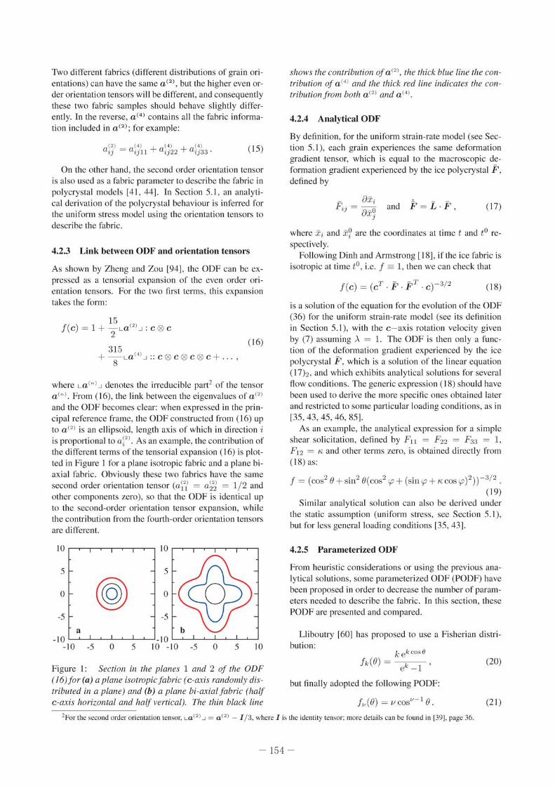
<lnd the ODF becomes clear: whcn expressed in the principal reference framc, the ODF constructed from (16) up 10 a (21 is an el lipsoid. length axis o f which in direct ion i is proportional to a~2 ) . As an example, the contribut ion of the diffe rent terms of the tensorial expansion ( 16) is plotted in Figure I for a plane iSOlropic fabric and a plane biaxial fabri c . Obviously these two fabrics have the same second order orientation tensor (ai'? = a~2d = 1/ 2 and othcr compone llls zero), so that the ODF is identical up 10 the second-order orientation tensor expansion. while the contributi on from the fourth-ordcr orientati on tensors are different.
10 10
5 5
@ 0 (@) 0
-5 -5 , b
-10 -10 -10 -5 0 5 10 - 10 -5 0 5 10
Figure I: Section in the planes 1 and 2 of tfle OOF ( 16)jor (a) a plane isotropic fabric (c-GJ.·is randomly distributed in a plane) and (b) a I)lane bi-axial fabric (half c -axis horizontal and half I'utical). TIl e rhin black line
shows the contribution of a(~) . the thick blue line the COIItribution of a(~ ) and the thick red fine indicates the contributionfrom borh a( ~ ) ami a (4 ) .
4.2.4 Analytical ODF
By definition , for the unifoml strain-rate model (see Section 5.1). each grain expcriences the same de formation grad ient tensor, which is equal to the macroscopic deformation gradient experienced by the ice polycrystal F, defi ned by
- 8:Ci Fij = '::'-0
u X j <l nd (17)
where Xi and x? are the coordinates at time t and to respectively.
Following Dinh and Armstrong [ 18J , if the ice fabric is isotropic at Lime to, i.e. f == L thcn we can check that
is a solution of the equation for the evolution of the ODF (36) for the uniform strain-rate model (see its definition in Section 5.1), wi th the c - ax is rotation velocity g iven by (7) assum ing). = 1. The ODF is then onl y a fu nction of the deformation gradient experienced by the icc polycrystal F . which is a sol ution of the linear equll tion (17b, and which ex hibits ana lyt ical solutions for sevcral flow cond itions. The generic expression (18) should have been used to deri ve the more spec ific ones obtained laler and restricted to some particular loading conditi ons, as in [35 , 43, 45,46, 85J.
As an example, the analytical expression for a si mple shear solic itation , defined by FIl = P22 = F33 = 1, Ft2 = Ii <lnd other terms zero. is obtained directly from ( 18) as:
f = (oos20 +sin20(cos2rp + (sin i.p + licos rp)2)) - 3/2 . ( 19)
Similar analytical solution can also be derived under the static assumption (uniform stress. see Section 5.1 ), but for less general loading conditi ons [35, 43J.
4.2.5 Paramelerized ODF
From heuristic considerations or using the previous analytical soluti ons, some parameterized OOF (PODF) have been proposed in order to decrease the number of parameters needed to describe the fabric. In th is section, these POOF arc presented and compared.
Lliboutry [6OJ has proposed to use a Fisherian distri-bution:
kek oos O
e" - 1 •
but fina lly adopted the following POOF:
f,, (O) = /.IooS ,,-tO .
(20)
(2 1)
2For the ~e(:on d order orientation ten,or. LOP ).J "" aP l - 1/ 3. where J is the identity ten-or: more detail. can be found in [391. page 36.
-154-
Meyssonnier and Ph ili p [671 used a d iscreti zcd ODF over 90 intervals between 0 and 1r / 2. They showed th at the di screti zcd OOF can be very accurate ly fi lled using the following POOF:
From an analytical solution. GOdert 1431 has dcrived a semi-parameteri zed ODF restricted to pl anar fl ow. Assuming that the direction 3 is the d irection perpendicular 10 the plane flow. the proposed POI)F takes the form:
[a.b,c(O,({!) = [>. - 2/3 COSZ 0
+ (a + bsin 2({! + CCOS 2({!)"\ 1/3 sin2 Or3/ Z , (23)
where ,.\ = e - 3 L t.tD~~ . In (23), onl y Ihe in-pl anc form of the fabric is paramcterized since the concentra tion perpendicul ar to the pl ane fl ow is give n analytically as a function of the strain-rate normal to the plane fl ow (D 33).
Using the same an;llytical approach 135J. Gagliard ini a nd Meyssonn ier have proposed a PODF for an OT
thotropic f<l bric [36J:
h, ,l.: l,<,oo(8 ,({!) = [(k]kz)-2 cos2 8
+ s in2 8(kr cos2 «{! - ({!o) + k~ sin2 «{! - ({!0»]-3/2.
(24)
The two p<lrameters kl and k2 control the f<lbric strength , whereas !Po g ives the inclination of the mmeri al symmetry reference frame in the particul ar case of planar fl ow.
PODF (23) and (24) lead 10 exactly the same orientation distribution since analytical re lations3 C3n be obtained betwecn the two sets of parameters (kJ, k2 , !Po) and (a, b, c, ,.\ ). Using the conservation equation (1 2) in (23). one of the four parameters can be expressed as a function of the three others: a = (b2/sin(arctan(b/ c))2 _ 1) ]/2 .
Noticing thm most o f the observed fabrics have <I vertical axis o f rot<ltional symmetry, lllOrsteinsson L86] built his POOF by assuming a uniform distribution with in Ihe two a ngles 0"0 and 0, such Ihat:
1 rr 100.0(8) = ----- ,O S 00 S () S a S?
cosOo cos a _ (25)
More recently, Placidi ;l nd Huller 179J h;lve 3dopted the following POOF:
; (B - Bo ) [o,,(B) ~ 'B •
8m 0 (26)
where 0 denotes the Dirac function.
Except for (23) and (24), all the other POOF found in the literature are restricted to a fabric which shows a rotational symmetry. Since all these POOF arc expressed in the material symmetry re fere nce frame of lhe polycrystal, two Euler angles have 10 be added 10 the set of paramelers to give the posit ion of the fabric symmetry ax is relative to a general reference fm me. The PODF (23) and (24) incl ude the orientati on of one of the axes of the material symmetry re fere nce frame, and arc restricted to the partic ul ar case of a planar fl ow. For more complex flow, one should for example SCI !Po = 0 in (24) and usc three Euler angles to fi x the material symmetry re ference frame rel ative 10 a general reference frame.
Except for (22) and (23), all the other POOF fulfil implicitly the total volume conservation ( 12). No simple relation was found for the three parameters in (22) in order 10 ex press one of the parameters as a funct ion of the two others. As a consequence, neither combination of the three parameters q; in (22) guarantees thallhe volume conservation is fulfilled. Thi s condition must be verified afterwards, which in reality render the usc of this POOF very complicated.
Except for (26), all the presented POOF reduce to the expected value 1 = 1 fo r isotropic icc.
As presented in the prev ious section, the orientation tensors allow <In objecti ve compari son of f<l brics. Assuming a tr<l nsversely isotropic f<l bric around e3, i.e.
(2) _ I 2 (ll (21 _ (2) . d - 0 'r '-'- ' a33 - - all , all -a22all a'j- 1 ~r J , onecan
compare the different PODF for a give n a~~ . The relation between the PODF parameter(s) 1) and a~2d is given by:
rl' a~i = 10 j,)(O) COS
2 OsinOdO, (27)
and therefore a~j = [(k 2 - 2k + 2)ek - 2J1[(k2(Ck - 1)]
and a~i = v/ (v +2) for Ltiboulry 's PODF (20) and (2 1),
respectively, a~i = (cos2 00 + cas 00 cosa + cos2 0')/3 for lllOrslcinsson 's POOF (25) and a~i = cos2 ()o for Pl ac idi and HUller's PODF (26). [n the case of a transversely isotropic fabric, k, = k2 • and the Gagli ardi ni and Meyssonn ier's rODF (24), as well as the GOdert 's PODE is only a function of O. Foll owing [35]. an analytical relation can be derived between a~i and the PODF parameter k\ (from equations (40), (42) and (43) in 135]).
Since the Thorstcinsson 's PODF (25) depends on two parameters, for a given value of a~j , Ihe choice of these two parlllTIctcrs is nOI unique. As done by Thorslci nsson [86], one can adopt no = 0 for single max imum fabrics (cone fabrics), but as far as a~j < 1/ 3 (girdle fa bric), the parameters must verify no :?: a !'ccos ( 3a~j) I / 2 and a = 1r / 2.
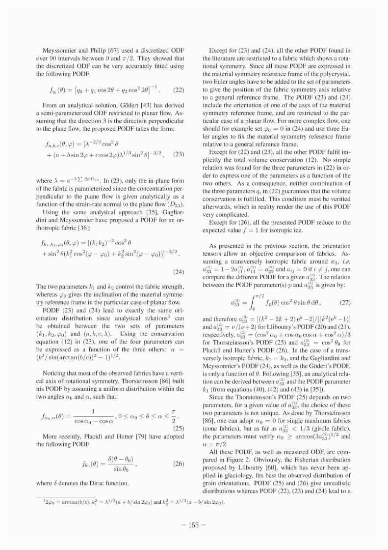
All these PODF. as well as measured ODE are compared in Fi gure 2. Obviously. the Fisherian di stribut ion proposed by U iboutry 160J, which has never becn applied in glaciology, fits best the observed distribution of grain orientations. PODF (25) and (26) g ive unrealistic distribut ions whercas PODF (22), (23) and (24) lead to a
32r.po = a rc t nn (b/c) . k~ = A 1/3(a + b/ s in 21"0) and k~ = A 1/3(0 - b/ s in 21"0) .
-155 -
too much concentrated fabric. Sincc the POOF (23) and (24) werc derived from an analytical solution assuming that the grain rotation is on ly the result of the gl ide of disloc:uions along the crystallograph ic planes, thc ditTcrence between the measured fabrics and the PODF (23) and (24) might be explaincd by the rotation recrystallization which has the effect of decrcasing the fabric strength in compression.
d " , • • • • " " • • " • • • • • "
, • • , " • " " • •
Figure 2: Comparison oflhe differel1l PODF - ~-(20). - A
(2 1), -. -(22), -__ (23) and (24), -. -(25) alld -110 ~")"mbol
(26)for (a) a~j = 0.20. (b) a~'d = 0.44. (c) a~'d = 0.60 alld (d) ail = 0.78. The Ihick red curve represellls measuremelllS from lite Dome C core for lire same ralue of a~j and ai'i ::::: a~2.] (G. Durand. /Jersonal communicalion).
The choice of a PODF implicitly determines all thc even order orientation tensors. Even if for a particular value of the parametcr{s) of the POOF, one can obtain the sollne second-order orientation tensor, the higher order orientation tcnsors will be different (clse the PODF curves in Figure 2 would be superimposed). Thcrefore. even for the samc sccond-order oricn\<ltion tensor and the same homogenization model. the polycrystal response should he different for all these PODF.
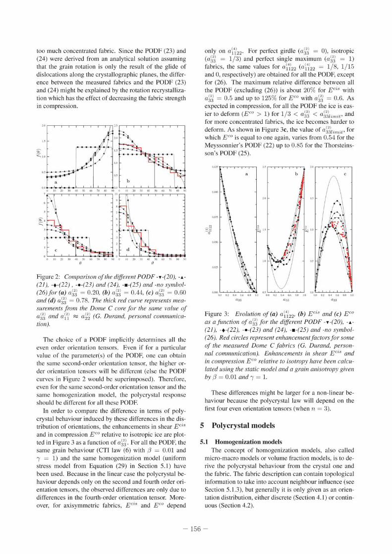
In order to comparc the difference in terms of polycrystal behaviour induced by these ditTerenccs in thc distribution of orientations, the enh ancements in shear E el! and in compression E CO relative 10 isotropic ice arc plotted in Figure 3 as a fU llct ion of a~j . For all the POOF. the same grain behaviour (CTJ law (6) with f3 = 0.01 and 'Y = 1) and the same homogenization model (uni form stress model from Eq uat ion (29) in Section 5. 1) have becn used. Because in the linear case the polycrystal behaviour depends on ly on the second and fourth order orientation tensors, the observed differences are on ly due 10 dificrences in the fou rth-order orientation tensor. Moreover, for ax isymmetric fabrics, Eei
$ and EGO depend
only on ai4izz. For perfect girdle (a~j = 0), isotropic (a~j = 1 / ;~) and perfect single maximum (a~j = 1) fabrics , the same values for a\4i22 (a j·i22 = 1/ 8, 1/ 15 and 0, respectively) are obtained for all the POOF. except for (26). The maximum relative difference between all the PODF (excluding (26» is about 20% for E ei. with aYd = 0.5 and up to 125% for EGO with a.~j = 0.6. As expected in compression, for all the POl)F the ice is easier to deform (Eeo > 1) for 1/ 3 < a~j < a&jum ;r, and for more concentrated fabrics. the icc becomes harder to deform. As shown in Figurc 3c, the value of a &j/,m it ' for which EGO is equal 10 one agai n, varies from 0.54 for the Mcyssonnier's POOF (22) up 10 0.85 for the Thorsteinsson 's POOF (25).
Figure 3: El'olulioll of (a) ai"i22. (b) E ci8 alld (c) E eo as a/uncrion 0/ a~'d for II,e different PODF - ~ -(20). -, (21). -. -(22). -__ (23) alld (24). -. -(25) and -I/O symbol(26). Red circles represelll en/wllcemell ifaciors/or some of Ihe measured Dome C fabrics (G. Duralld. perSOI/na/ commllllicatioll). En/wllcements in shear Eci~ alld in compression ECO relatil'e 10 isolropy halle beell calculated IISill8 lite slatic model alld a grain anisolrop)" given by f3 = 0.01 alld 'Y = 1.
Thesc differences might be l<lrger for <l non-linc<lr beh<lviour because the polycryslal l<lw will depend on the first four evcn orientmion tensors (when n = 3).
5 Polycrystal models
5. 1 Homogenization models The concept of homogenizmion modcls, also called
micro-macro models or volume fr<lction models, is 10 derive the polycrystal behaviour from the crystal one and thc f<lbric. The fabric description can contain topological informat ion to take into account neighbour innuence (see Section 5.1.3), but generally it is only given as an orientation distribution, either discrete (Section 4.1) or continUOliS (Section 4.2).
-156-
The dilTerence between all the homogenization models comes from thcir formulations and the hypotheses, implicit or explicit, used to take into account the grainto-grain interaction.
For all these models, the macroscopic strain-rate b and the macroscopic deviatoric stress S are evaluated as the average of the strain-rate and deviatoric stress, respectively. over all the grnins that compose the polycrystal;
b =< D > and S =< S > . (28)
The average < . > is either defined by (10) for a discrete description of the fabric or by (13) for a continuous one.
5.1.1 Static and Taylor bounds
T he Taylor model assumes a uniform strain-rate distribution over all the grains, so that the strai n-rale experienced by a grain is the same as that experienced by the polycrystal considered as a homogeneous medium: D = b. On the other side, the static model supposes a uniform stress distribution (8 = S). For a given applied strai nrate, the static and Taylor models provide the lower and upper bounds, respectively, for the d issipation potential
1541. Due to the strong crystal anisotropy, the static model
has been shown to be well adapted to describe the polycrystalline ice behaviour, whereas it is the opposite for the Tay lor model [II J.
11le static model has been onen used either with a discrete description of the fabric 110, 91j or a continuum description l35 , 45, 50, 85], mainly because it allows analytical developments. Using either the CTI law (5) or (6) and the orientation tensor to describe the fabric, analytical expressions for the static model can be derived easily. As an example, this expression using the CTI law (6) with 'Y = 1, simply reads:
jj ~ 12 (rJS + (1 - iJ)(a"' · S + S· aP ')] 2 (29)
+ 1h ({3 - 1)a (4) ; S.
As shown by Equation (29), in the linear case, the macroscopic expression depends on the first two even order orientat ion tensors.
In the limit case of an isotropic fabric , the second and fourth order orientation tensors simply read a;~) = 6ij / 3 and aj;~l = (dij dkl + 6ik 6j/ + 6i/ djk)/15 (i,j, k , l = 1, 2, 3). The static law (29) reduces then to the isotropic Glen's law ( I), and the following relation between the grai n parameters" tPl, (3 and 'Y, and the macroscopic Glen's law nuidity 8 1 is obtained:
For a one-site model, the grain-to-grain interaction is not taken into account, so that the behaviour of a polycrystal with a single maximum fabric is fully equivalent
to that o f the single crystal. Therefore, the grain parameters should be identified. not regard ing the crystal behaviour, but from experimerllal tests on a polyerystal with a strong single maximum fabric. Experimentally, it is then found thm such a polycrystal is approximately 10 times easier to shear perpendicular to the mean c-axis orientation than a polycrystal with an isotropic fabric [78J. The ratio I/Jd Bl = 10 can then be used to select the parameters ({3, , ). For the static model , the max imum value for this ratio is 5/ 2 in the linear case and 35/8 = 4.375 when n = 31601. Thecxperimcntal rat io o f 10 is then not reached by the static model, and th is is the main drawback of th is model. With the static model , the an isotropy enhancement of the now is always underestimated for single max imum 1:1brics by a factor 4 in the linear case and greater than 2 when n = 3. The use of intermediate models, as presented below, allows to avoid th is drawback.
5.1 .2 Visco-Plastic Self-Consistent (VPSC) model
The VPSC model has been adapted to ice by Castelnau and others [II J using a d iscrete description o f the fabric. As shown by Castelnau and olhers 112] from mechanical tests on GRIP (Greenland) ice specimens, this model reproduces adequately the dependence of the ice rheology on its fabric. The VPSC model is a so-called aile-sire approximation in which the innuence of the neighbourhood of each grain is accounted for by considering this grain as an inclusion embedded in a homogeneous matrix. the so-called homogeneous equil'alellf medium (HEM). The HEM behaviour, which represents that of the polycrystal, is to be determined. The basis of the VPSC homogenization scheme is the local illleraclionjorlllufa that provides a relation bet ween the local stress and the local strain-rate acting on a grain (different from grain to grain) and the corresponding macroscopic quantities. II is written as
D - jj ~-M' (S - S) , (3 1)
where the interaction tensor A1 is a function of the grain and of the (unknown) HEM mechanical properties (see Equations (17-19) in [II] for details). By construct ion, if the same stress sensitivity cxponcnt is adopted for all the crystallographic planes. then the HEM and the grain will have the same exponent. The macroscopic behaviour of the HEM is obtained by solving the equation b =< D >.
To solve this equation. Castelnau and others used the averaging formula (10) and the Schmid law (4) with a stress exponent n = 3. In the non-linear case, the results are strongly dependent on the linearisation of the local behaviour, leading to the so-called secant. tangenr and affine formulations; however. Castelnau and others used only the tangent formulation [9J. T he above assumption may be questionable for icc, where a strong directionality and large variations in local properties arc expected.
"Formally. 10 obtain relation (30). one ~houtd derive an exprc"ion ~imi1ar 10 (29) without as~uming ')' = I.
-157 -
FurthemlOre, the tangent formulation was shown to saturate for high anisotropy [42J. The non-dependence with higher-order statistical moments is particularly crit ical for the treatmelll of those highly-contrasted materials, since such information is essential to capture, in an average sense, the effect of the strong strain-nile gradients that are likely 10 develop inside grains which are highly anisotropic. In order to overcome the above limitations, Lcbensohn and others have applied to ice a rigorous nonlinear homogenization scheme, the second-order VPSC model, that takcs into account informat ion on the avcrage fiekl fluc tuations at thc grain level [56[. Among the various nonlinear extensions of the self-consistelll approximation, the secolld-order method gives the best overall agreemelll wi th the effective properties and field fluctuations obtained by means of full-field simulmions (see below), for both 2-D and 3-D polycrystals [56J.
In the linear case, there is only one formulation for the VPSC model, and the macroscopic behaviour of the HEM can be obtained by solving either the equation b =< D > or 5 =< 5 >. Meyssonnier and Philip have derived a semi-analytical solution in this particular linear case, using the CTI modcl (6) with '"Y = 1 for the grain and an ODF with transverse symmetries to describe the fabric [67].
When using the VPSC model it is not possible to achieve the HEM behaviour in closed analytical fonn. The ratio t/Jn/Bn of the isotropic fluidity obtained with the VPSC model (on an isotropic fabric ) 10 the grain reference fluidity ¢n must be computed. In the linear case, Meyssonnier and Philip [67] derived the following relation when I = I:
(32)
This relation can be used to choose appropriate values of grain paT(IITleter {3 when I = 1. As an example, the expected experimental value of 10 is obtained for {3 = 0.04 and I = 1 [67], In the non-linear case with the tangent linearisation scheme of the VPSC, Castclnau and others [9[ estimated from a comparison with experimental tests that the RRSS for the pyramidal and prismatic planes should be 70 times larger than the basal plane RRSS (rr ~ rt y ~ 70r8)·
S. J.3 Topological models
For this particular elass of homogenization models, the fabric description contains some topological information so that the neighbourhood is taken into accou nt to estimate the stress and strain-rate of a partic ular grain. Azuma and Goto-Azuma [5J and Thorsteinsson 187[ have developed topological models in which the fabric descript ion is discrete and the grain deforms only by basal glide with 71 = 3. In both approaches, the local deviatoric
stress is evaluated from the macroscopic one as:
S'i = O'ij S ij (no sum) , (33)
where O' ij is the neighbourhood interaction coefficicnt tensor.
In Azuma and Goto-Azuma [5] , thc neighbourhood interaction coefficients are estimated as
«l'ij » O' ;j = ~
Tij
(34)
where « . » denotes the local average over the neighbour grains on ly, and r ! is the Schmid tensor (3) for one particular direction in the basal plane, determined as the maximum resolved shear-stress direction when the macroscopic stresses act on the grain.
Thorstcinsson [871 has adopted a scalar neighbourhood interaction cocfficient. defincd as:
( «I L (r ' , S )b'l ») 1
a.;~ a ~ (+, IL (r' ,S)b'l «(+ 6,) '
(35) where « » denotes the local average over the six ncighbours, and L:& is the sum over the three sl ip systems of the basal plane. The two parameters C and ~ allow to modify the relative influence of the 6 neighbours: (C,~) = (1, 0) reduces 10 the uniform stress model, when ((, ~ ) = (6, 1) the centre crystal contributes as much as all the 6 neighbours and when «(,~) = (1, 1) the centre crystal contributes as much as each of the neighbours. Note th;!t the fabric evolution. as well as grain growth, rotation and dynamic recrystallization are implemented in Thorsteinsson's model [87].
Azuma and Goto--Azuma [51 have first highlighted the possible directional effects of anisotropy on the formation of stratigraphic disturbances. By using their pol ycrysta lline law, they have shown that at a deeper part of an ice-sheet , where a single-maximum fabric develops, a positive vertical strai n-rate can be produced with on ly a horizontal shear stress as far as the bedrock is not nat. Using the feature that a polycrystal with a single maximum fabric is easier to shear but harder to compress, they noticed that a small misorientation of the mean orientation of the c·axes could induce disturbances of the layers. For a vertical variation of the mean orientation, both layer thinning and thickening can occur depending on the mean orientation of the c-axis. If it varies horizontally, then layer folding or boudinage could occur. These two scenarios are only qualitative because in L5J the complex interaction from the surrounding layers was completely neglected.
The so-called cell ular automaton models [30. 551 can also be included in the class of the topological models. Based on a cellu lar automaton algorithm, this approach allows the modelling of several compet ing proccsses acting on the fabric evol ution, like defonnation,
-158-
grai n growth and contin uous and discontinuous rccrystallizations. For numerical reasons, applications arc limitcd 10 two-dimensional thin section, and the stress is assumed uniform in all the grains. which is the main difference 10 the full-field models presented below.
5.2 Phenomenological models In a phenomenological model, an anisotropic macro
scopic formu lation for the polyerystal law is postulated. To be usable, the rheological parameters that enter this law have to be evaluatcd as a function of the fabric. The form of the law is assumed to be restricted to particular kinds of anisotropic symmetries (orthotropy, transverse isotropy or even isotropy), and the approaches mainly differ on the way the rheological parameters and the fabric are linked. In the Morland and Staroszczyk approach [69,70,71 , 72,80,81,83,84], the anisotropic parameters arc solely phenomenological functions of the deformation, and there is no dirccl link with a fabric descriplOr. The limit values of the strain functions are evalu:lled from experimental resul ts or by comparison with an homogenizat ion model [82[.
On the c011lrary, the six rheological parameters e11lering the Gillet-Chau let and others [40] law arc simply fi tted using a homogenization model , like the VPSC model presc11Ied above. In the first formulation, the fabric was described using the parameters of the PODF (24) l40J , but th is approach was found not to be cfficient for the fabric evolution. so that thc f<Jbr ic was later described by the usc of the second orientation tensor [411.
In the approach of Placidi and Hutter l79J, the Glen's now l:\w coll inearity between strain-rate and stress tensors is assumed to be conserved, and the anisotropy is taken into account by introducing;ln anisotropic enhancemcnt factor. This anisotropic enhancement factor is a func tion of the so-called de[ormabilit)' of the polycrystal, evaluated from the fabric and the actual macroscopic stress. The anisotropic enhancement factor varies from 0 for a single maximum fabric undcr compression up to a maximum valuc E8 for the same fabric but solicited by simple shear.
The main interest of these models is their numerical efficiency, which allow thei r implementation in now models as presented in Section 6.
5,3 Full-field models
The full-field modcls solve properly the Stokes equations using either classical Finite Elemcnt methods [65 , 68] or Fast-Fourier Transforms [56, 57]. The laller has beller performance than a Finite Element calculation for the same purpose and resolution, but only works for periodic boundary conditions. In such an approach, each crystal is decomposcd in many clements. allowing to infer the stress and strain-rate heterogeneity at the microscopic scale. As an important result, these models show that, for a given orientation, the mean strain-rate rllld stress are strongly dependent on the neighbour grain orientations. All the same, the average value of all grains
having the same orientation is still dependent on this orientation. In other words, certainly becausc the ice is strongly an isotropic, the neighbourhood infl uence docs not counteract the orientation influence when looking to average behaviour of a large number of grains having the same orientation , but only induce a strong variability.
The rTf results in [57] clearly contradict the statement made by Faria and co-authors [28, 29, 31J that stress and strain-rate of a speeies, i.e. an cnsemble of grains having the same orientation. should be independent of its orientation because of the huge number of gmins belonging in the same species. As discussed by Gagliardini [33], the assumption made by Faria and others seems to be not insignificant and should he comparable to a uniform strain-rate or Taylor assumption in the framework of the homogenization model (for a complete discussion of this subject, see also the reply to Gagliardini's comment [33J by Faria and others [32]).
5.4 Fa bric evolution When thc fabric is described using thc discretc ap
proach, thc strai n-rate and the spin for each constituent can be evaluated from the homogenization model and the grain c - axis rotation is simply calculated from Equation (7) l13, 87, 91J. This formula also holds for evaluating the c - axis evolution for the full-fie ld models ["65].
Using an ODF, GOdert and Huller 1451 have proposed to adopt the following equation for the local balance of theOOF:
j + dive(cf) = rr' + div:c w£ + diVe w{ , (36)
where diVe and div::t: denote the divergence operator in the orientation and Cartesian spaces, respectively, rr' is a production o f orientation, w{ is associated with the diffusion of orientation in the orientation space and w~ describes diffusion of crysta ls from one region 10 the neighbouring one. Such production and diffusion terms should be used 10 take into account the different recrystallization processes. Nevertheless, the cominuity equation (12) only holds when thcse terms arc neglected.
The PODF (23), (24) and (25) have been used to express the fabric evolution equation as a set of POOF parameter evolut ion equations for some special now conditions and under the static assumption. This is achieved by replacing f in Equation (36) by the POOF expression. lllen , a set of equations for the evolution of the parameters is derived by choosing as many particular orientations as the number of parameters in the PODE Therefore, the resulting parameter cvolution equations are not necessarily unique. Gagliardini and Meyssonnier 138J havc shown that, in the case of 2D plane-strain flow, this method leads to a unique set of three cquations for the three parameters kl ' k"l and '-Po for thc POOF (24). This result was not achieved in a more general 30 flow. Thorsteinsson and others r891 have derived a simple
-159-
equation for the cone: angle 0 ' in (25), by a straight-line fit of the results obtained with a discrete model [87[.
Using the orientation tensor, the fabric evolution can be described at the macroscopic sca le from the temporal derivation of the second order orientation tensor ( 14), as:
a (2)=< c (8) C>+< C® C> . (37)
The rotation rate c of the c - axis given by (7), is a function of the microscopic spin and strain-rate and should therefore be expressed as a function of macroscopic quantities if one wanls to derive an explicit equation for the evolution of the second order orientat ion tensor. This is si mply achieved for the Taylor model and also for the static one for which D = tPn/2T,,- 1 S. For imermediate models. Gi.)dert [44J. and Gillet-Chaulet and others [41], have proposed to adopt the following expression for the rotation rnte of the orient(lt ion of n crystnl :
. - - T -c = W ·c - [C·c - (c ·C·c)c], (38)
where 6 = (1 - alb +a!/J,, -r n- 1 S / 2 is a tensor, equi valent to a strain-rate, intermediate between the Taylor and slatic strain-rates. The sca lar inleraclion parameter a allows to describe intennedinte fnbric evoluti on, from the Taylor case (0' = 0) to the stntie case (0 = 1). In [44], the macroscopic stress and strain-rate (Ire evaluated using the static model, whereas Gillel-Chaulet and others f41] used the VPSC approximation.
Using Ihis intermediate notation for the rotation rate of the orientation of a crystal, its follows from (37) that the evolution of the second order orientat ion tensor reads:
uP) = W · a (2 ) _ a (2) , HI _ (C· a ( 2 ) _ a ( 2 ) ·6) + 2 a (4 ) : C.
(39)
Equation (39) for the evolution of a(2 ) involves the fourth-order orientation tensor a (4). The same procedure applied to a ( 4 ) would show that fi (· ) depends on a (e), and, in general, th at any evolution eq uation for an even-order orientation tensor fi (2p) will involve the next higher even-order orientation tensor a (2P+2) . To obtain a closed set of equ:uions we must SlOp at a given order 2p and make a so·called closure approximation, i.e. postulate a relation between a (2p+2) and a (2p) . Using a elosure approxi mat ion for a (4 ) leads to the assumption of macroscopic orthotropy [15].
Orientation tensors arc widely used to provide a compact representation of fiber orientations in reinforced composites, and many closure approxi mations have been proposed (see for example [I , 14, 15J and references therein). A simple form for the closure approximation. known as the quadratic closure, is:
(40)
Note that the quadrat ic closure does not respeel the symmetries of a ( · ) and is on ly exact for a perfect single maximum fabric.
A second approach, the linear closure, is built from all the possible products of a ( 2 ) and the identity tensor 1 that respect the symmetries of a ( 4 ) :
7d;;~1 = - ~ (O;jl5kl + OikOjl + Oi/Oj k') + a~j)ON + (2H + (2) ~ + <" J + ( 2 ) ~ + ( 2 ) ~
a ;k Oj l a il Oj k aN ij a jl Oik a j ko i/ .
(41)
Adv;lIli and Tucker II] have proposed an hybrid closure constructed from the two prev ious ones :
where 2af = 3 a ( 2 ) : a ( 2) - 1. Since Of = I for a single maximum fab ric and a f = 0 for an isotropic one. the hybrid closure is exact for both cases. The hybrid closure was applied 10 icc by GOdert [44J.
Gil1ct-Chau let and others [41 J have used the /m'arial1fBased Optimal Filling (I.BOF) closure from Chung and Kwon LJ4J. Its general form is
a (4 ) =/31 ( I (8) I )D + f32( 1 (8) a ( 2 )D
+ /33( a (2) (8) a ( 2) )D + /34(1 (8) a ( 2). a (2 ))D
+ /3s( a ( 2 ) ® a ( 2 ) . a ( 2»)D
+ /36(a (2 ) . a (2) (8) a ( 2 ) . a ( 2) )D ,
(43)
where 1 is the identity tensor, and the six functions /3i are functions of the second and th ird invariants of a(2),
denoted by II and III respectively. It can be shown that, owing to the symmetries of a (4 ) and the nonmllisation condition tr a ( 2 ) = 1, only 3 functions /3i arc independent. Following Chung and Kwon [14J, Gillet-Chau let and others f41 J have taken the three independent functions as complete polynomials of degree 5 in II and III , so that 63 parameters need 10 be determined. By adding two other relations to insure that the IBOF closure approximation is exact for perfectly aligned fabrics and girdle fabrics , this number is reduced to 61.
Gillet-Chaulct and others [4 1 J have computed these 61 coefficients so that a (4) given by (43) fits the fourth order orientation tensor calculated by using POOF (24) (sec Annex C of[ 39] for the values of the 6 1 coefficients). The IBOF closure is much more accurate than the hybrid closure and, in the linear case (n = 1), it conducts 10 the same fabric evolution than the one obtained by solving the evolution equations for the parameters of the POOF (24), but in a much faster Wily.
Both the hybrid and mOF closures assume implicitly that the fabric is orthot ropic. To avoid this hypothesis, which should not be so strong for polycrystal ice, one can compute the evolution of a (4 ) . but must then adopt a closure upproximation bet ween a(4 ) and a (6 ) [50J.
6 Flow models of anisotropic polar ice
In order to study the influence of icc anisotropy on the flow of icc-sheets, a modell ing efforts have been made in
-160-
order to implement anisotropic laws in flow models, and for a few applications, the anisotropic flow laws have also been coupled with the strain-induced fabric evolut ion.
6. 1 Flow of anisot ropic ice In the framework of the Shallow Icc Approximation
(SIA) [491, initially developed for isotropic ice. Mangeney and Califano [621 have proposed the extension to an isotropic icc of the SIA up to the second order. They have adopted the static transversely isotropic law of Lliboutry [60J, in which the fabric is described by the POOF (21). The symmetry axis of the fabric coincides with the vertical axis, and only vertical changes of the fabric strength arc allowed. Mangeney and Califano [621 have shown that the zero-order :lpproximation of the anisotropic SIA is fully equivalent to the isotropic SIA with an enhancement factor. However, when the second-order correction is calculated, the isotropic SIA with an enhancement t:1ctor docs not correspond to the anisotropic SIA anymore. By comparing the anisotropic SIA to an exaCT solution, Mangeney and Califano [62J have shown that for a perturbed bedrock, the seeondorder approximation is needed.
lliese developments were further extended by Philip and Meyssonnier [77J to the case of a non-vertical symmetry axis of the fabric. They have shown that the diagonal eomponems of the devialOric stress can be of the same order as the shear stress when the material symmetry axis is not vertical, clearly indicating that the above conclusion by M:lngeney and Califano regarding the enhanccment factor is only valid in thc restricted case of a vertical material symmetry axis. Moreovcr, Philip and Mcyssonnier havc shown that thc solutions at orders grealer than zero remain negligible in the particular case of a linear rheology and a flat bed.
Using the same Lliboutry·s polycrystal model as in [621. Mangcney and others [63, 641 have developed a two-dimensional isothermal full-Stokes model restricted to Newtonian behaviour, withoUl[63] and with 1 6~]tak
ing into accoum the free surface evolution as a func tion of an imposed accumulation. In th is approach, the fabric is given and is assumed to be a function of the relative depth only. In 164], they have shown that the effect of ~nisolropy is partly smoothed out by Ihe change of the free surface which is flallcr in the ~n isotropic case than in the isotropic case. In the p~rticul~r case of a sinusoidal bedrock, the anisotropic ice above the bump is found 10
be younger by more than 10 % comparcd 10 the isolropic icc. and in the holes of the relief it is older by more than 100 %.
Morc recently. Pettit and others [76J have developed a flow model. in which the ice fabric is described using the cone-angle POOF (25), and the :ln isotropic icc behaviour is inferred from analytical solutions derivcd under the Sialic assumption for simple loading cases in [86]. Be-
cause Pettit and others [761 consider complex load condi tions in their flow model, these analytic:l1 results were linearised. and the flow non-linearity was re- introduced by the usc of an iSOlropic bulk elTective viscosity derived from Glen's law. Assuming that the cone-angle profile is only a function of reduced depth, this non-linear model was applied to study the flow ncar an ice divide. They have shown that a Strong crystal fabric always increases the amplitude of the existing arch in the isochrones, the so-called Raymond bump, relative to the isotropic case. They h:lve confirmed that with a linear flow law, no arch exists in either the anisotropic or isotropic case.
6.2 Flow and fabric evolution of anisotropic ice
GWert [43] and GWert and Hutter 146] have developed an anisotropic flow model with induced anisotropy using a coupled Finite-Element Finite-Volume approach. In their approach, the Newtonian orthotropic behaviour of icc is inferred from the static model , the fabric is described using the POOF (23) and ils evolution is intermediate between the Taylor and sl3tic models (Equation (38)). As a first application, th is flow modcl was appl icd to a rectangular domain 10 times wider than th ick in order to reproduce thc stationary plane flow in the vicinity of an icc divide. The resul ts obtained at the divide weTt! shown 10 reproduce well the evolution of fabric along the GRIP core.
Also using a static Newtonian orthotropic model and a fabric given by the POOF (24), Gagliardini and Meyssonnier have applied their anisotropic flow model 10 a 21) synthetic icc-sheet geometry [36] and to study the fabric evolution along the GRIP ice core [37]. In this later application, they ha.ve shown, by comparing the fabric evolution obtained with the 20 flow model to the fabric evolution inferred from a Oansgaard-Johnsen one dimensional flow model [16], that the flow conditions clearly influence the fabric evolution. Because of this complex coupling between the flow and the fabric, the use of a trivial evaluation of the strain-Tate history, like a one dimensional Oansgaard-Johnsen model, renders the application of any polycrystalline model open to criticism when comparing measured and modeled fabrics.
Gillet and others 141] have presented a 20 isothermal orthotropic flow model wi th induced anisotropy and free surface evolution. The polycrystal behaviour is inferred from an orthotropic Newtonian phenomenological model using the VPSC solution to fit the viscosity parameters. The fabric is described by the usc of the orientation tensors. The velocity. pressure and fabric fields , as well as the free surface elevation, were calculated in a coupled way for a synthetic ice-sheet geometry. consisting of sinusoid:ll bedrock elevation. Their results show that, due to the bedrock irregularities, the icc fabric field presents a strong spatial variability. The same model was later applied to quantify the influence of a difference in the initial surfacc viscosity on thc fabric development [211.
-161-
Grain heterogeneities o
Polycrystal behaviour and fabric evolution Flow model
~3m 2D - - 3D 2D • Phenomenological models I I
H0!ll0genization models I Topological models
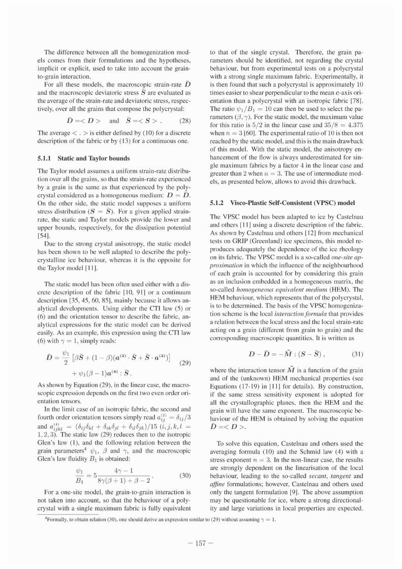
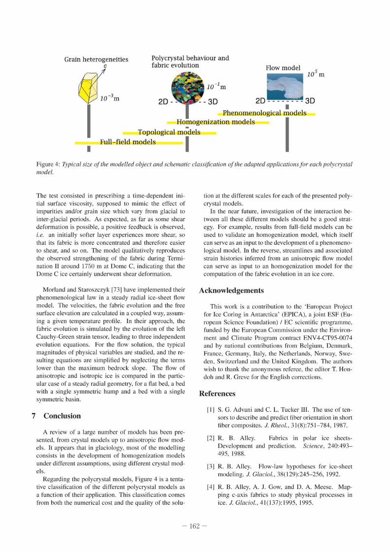
Full- field models I Figure 4: Typical size of Tf,e modelled objecT alld schemaric c/assificalioll of rhe adapTed appficariolls for each Pofyc/)'sTa/ //lode/.
The test consisted in prescribing a time-dependent initial surface viscosity, supposed to mimic the effect of impurities 'lIld/or grain size which vary from glacial to inter-gl<lci<ll periods. As expected. as far as some shear deformation is possible, a positive feedback is observed , i.e. an ini tially softe r layer experiences more shear, so that its f<lbrie is morc concentrated and therefore easier to shear, and so o n. TIlC model qualitatively reproduces the observed strengthening of the fabric during Termination 11 around 1750 m at Dome C, indicating that the Dome C ice certainly underwent shear defonmllion.
Morland and Staroszczy k !73J have implemented their phenomenological law in a steady radial ice-sheet flow model. The velocities, the fabric evolution and the free surface elevat ion are calculatcd in a coupled way, assuming a givcn temperature profile. In their approach. the fabric evolution is simulated by the evolution of the left Cauchy-Green strain tensor, leading 10 three independent evolution equations. For the flow solution, the typical magnitudes of physical variables arc studied, and the resulting equations are simplified by neglecting the terms lower than the maxi mum bedrock slope. TIle flow of anisotropic and isotropic ice is comparl.'<i in the particular case of a steady radial geometry. for a flat bed, a bed with a sing le sy mme tric hump and a bed with a single symmetric basin.
7 Conclusion
A review of a large number of models has been presemed, from crystal model s up to anisotropic fl ow models. [t appears that in glacio[ogy. most o f the modelling consists in the devclopmcnt of homogenization models under ditTerenl assumptions, using different crystal models.
Regard ing the polycrystal models. Figure 4 is a tentative classification of thc different polycrystal models as a func tion of their application. This elassification comes from both the numerical cost and the quality of the solu-
tion at the different scales for each of the presented polycrystal models.
In the ncar future , investigation of the interaction between all these different models should be a good strategy. For example, results from full-field models can be
used 10 validate an homogen ization model, which itsclf can serve as an input to the development of a phenomenologica l model. 1.11 the reverse, streamlines and associated strain histories inferred from an anisotropic flow model can serve as input to an homogenization model for the computation of 1he fabric evolution in an ice core.
Acknowledgements
Th is work is u contribution to the 'European Project for Icc Coring in Antarctica' (EPICA), ajoint ES F (European Science Foundation) I EC scientific programme, funded by the European COTllmission under the Environment and Climate Program contract ENV4-CT95-0074 and by national contributions from Belgium, Denmark, France, Germany, It aly, the Netherlands, Norway, Sweden , Swi tzerland and the United Kingdom. The authors wish to thank the anonymous referee, the ed itor T. Hondoh and R. Greve for the English corrections.
References
II J S. G. Advuni and C. L. Tucker Il l. The usc of tensors to describe and predict fiber orientation in short fibcrcomposites . J. Rheol., 31(8):751 - 784,1987.
!2J R. B. Alley. Fabrics in Development and prediction. 495, 1988.
polar ice sheetsSciellce. 240:493-
131 R. B. Alley. Flow-law hypotheses for ice-shect modeling. 1. Glacial., 38( 129):245- 256, 1992.
[41 R. B. Alloy. A. J. Gow, "d D. A. Moese. M,pping c-axis fabrics to study physical processes in ice. 1. G/aciof., 41 ( 137): 1995, 1995.
-162 -
[5] N. Azuma and K. GOIO-Azuma. An anisotropic flow law for icc-shcct icc and its implications. Ann. Glaciol. , 23:202- 208, 1996.
[6] N. Azuma and A. Higashi. Formation processcs of ice fabric pallern in icc sheets. AI/II. Glacial. , 6:130-134, 1985.
[7j N. AZuma, Y. W3ng, K. Mori , H. Narita. T. Hondoh, H. Shoji , and O. W3t3nabe. Textures and labrics in the Dome F (A ntarctica) icc core. Anll. Glacial., 29: 163- 168,1999.
18] N. Azuma. Y. Wang. Y. Yoshida, H. Nari ta, T. Ho ndoh, H. Shoji, and O. Watanabe. Crystallographic analysis of the Domc Fudj i icc core . In T. Hondoh. editor, Physics of Ice Core Records, pages 45-61. Hokkaido University Press, Sapporo, 2000.
L9j O. Castelnau. G. R. Canova, R. A. Lebensohn , 3nd P. Duv31. Modelling viscoplastic behavior of 3nisotropic polycryst311ine ice with 3 self-consistent 3pproach. Acra. Marer. , 45( II ):4823-4834, 1997.
[10] O. Castel nau and P. Duval. Simulat ions of anisotropy and fabric development in polar ices. Anll. Glaciol., 20:277- 282, 1994.
[II] O. Castelnau, P. Duval. R. A. Lebensohn, and G. Canova. Viscoplastic modeling of texture development in polycrystall ine icc with a selfconsistent approach: Comparison with bound estimales. J. Geopflys. Res. , 101(6): 13,851 - 13,868, 1996.
1121 O. C3stelnau, H. Shoji, A. Mangeney. H. Milsch, P. Du val, A. Miyamoto, K. Kawada, and O. Watanabe. Anisotropic behavior of GRIP ices and fl ow in central Greenland. Earth Planet. Sci. Letl., 154( 1-4):307- 322, 1998.
[13] O. Castclnau, Th. Thorsteinsson, J. Kipfstuhl, P. Duval. and G. R. Canova. Modelling fabric development along the GR IP ice core, central Greenland. Ann. Glacial. , 23: 194-201. 1996.
114] D. H. Chung and T. H. Kwon. Invariant-based opti mal fitting closure approxi mation ror Ihe numerical prediction or flow-induced fiber orientation. J. Rheol. , 46( I): [69- 194, 2002.
[15] J. S. C intra and C. L. Tucker 111. Onhotropic closure approximations for fl ow-induced fiber orientation. J. Rheol. , 39( 10): 1095- 11 22, 1995 .
116j W. Dansgaard and S. J. Johnsen. A flow model and a time scale for the ice core from Camp Century, Greenland. J. Glacial. , 8(53):2 15- 223 , 1969.
[17[ S. de La Chapel Ie. O. Caslelnau, V. Va. Lipcnkov, and P. Duval. Dyn3ll1ic recrystallization and texture development in icc as revealed by the study of deep icc corcs in Antarctica and Greenland. J. Geophys. Res. , 103(83):5091- 5[05, 1998.
[18] S. M. Dinh and R. C. Armstrong. A rheolog ical equation of state for semiconcentratcd fiber suspensions. J. Rheol. , 28(3):207- 227, 1984.
[19J c. S. M. D03ke and E. W. WoItT. Flow law in polar icc sheets. Nalure, 3 14:255- 257, 1985.
[20[ G. Durand, O. Gagliardini. T. Thorsleinsson, A. Svensson , J. Kipfstuhl, and D. Dahl-Jensen. Icc microstructure and fabric: an up 10 date approach to measure textures. 1. Glaciol., 52(179):619-630, 2006.
121J G. Durand, F. Gillel-Chaulet , A. Svensson, O. Gagliardini, S. Kipfstuhl. J . Meyssonnier, F. Parren in , P. Duval, and D. Dahl -Jensen. Change in ice rheology during climate vari 31ions - implications fo r icc fl ow modelling and dating of the EPICA Dome C core. Clill/. Past, 3( 1):155- 167, 2007.
]22] G. Durand. F. Graner, and J. Weiss. Deformation of grain bound3ries in polar icc. Ellr. Phys. Letl. , 67(6)'1038- 1044. 2004.
[23[ G. Dunllld, A. Svensson. S. Kipfstuhl , A. Persson, O. Gagliardini , F. Gillet-Chaulel, J. Sjolte, M. Montagnat , and D. Dahl-Jensen. Evolution of the tcxture along the EPICA Dome C icc corc. Thi~' issue.
[24] G. Durand, J. Weiss, V. Lipenkov, JM Barnola, G. Krinner, F. P3rrenin, B. Delmonte, C. Ritz. P. Duval, R. Rothlisberger, and M. Bigler. Effect ofimpurilies on grain growth in cold ice sheets. J. Geophys. Res. , 111:F0101 5. 2006.
[25[ P. Du val. Creep and fabrics of polycrystall inc icc under shear and compression. J. Glacial. , 27(95):129- 140, 198 1.
L26] P. Duval, M. F. Ashby, :md I. Anderm3n. Ratecontrolli ng processes in the creep of polycrystalline icc. 1. Phys. Chelll .. 87(21 ):4066-4074, 1983.
[27] P. Du val and O. Caslclnau. Dynam ic recrystallization of icc in polar ice sheets. 1. Physique IV ('I·uppl. 1. Phys.III). C3, 5:197- 205, 1995.
[28] S. H. F3ri3. Creep and recrysta llization of large polycrystall ine masses. I. General continuum theory. PIVC. R. Soc. A, 462: 1493- 1514,2006.
[29] S. H. F3ria. Creep and recryst311 izatioll of 13rge polycrystalline masses. Ill : Continuum theory of ice shcets. PIVC. R. Soc. A, 462:2797- 28[6, 2006.
]30] S.H. Faria, D. Ktitarev, and K, HUller. Modelling evolution of anisotropy in fabric and texture of polar icc. AIII/, Glacial. , 35:545- 551 , 2002.
[3 [ [ S. H. Faria, G. M. Kremer. and K. Hutter. Creep and recrys1311i z3tion of large po lycrystalline masses. n . Const itutive theory for crystalline media with transversely isotropic grai ns. PIVC. R. Soc. A. 462: 1699-1720, 2006.
-163 -
[32] S. H. Faria, G. M. Kremer, and K. Hutter. Reply to Gagliardini's comment on 'Creep and rccrystalliza~ tion of large polycrystalline masscs' by Faria and co~authors. Proc. R. Soc. A, 464:2803- 2809, 2008.
[33] O. Gagliardini. Commcnts on the papers 'Creep and reuystallization of large polycrystalline masses' from Faria and co-authors (2006). Proc. R. Soc. A, 464:289- 291 , 2008.
1341 O. Gagliardin i. G. Durand, and Y. Wang. Grain area as a statistical weight for polycrystal constituents. 1. Glacial., 50(168):87- 95, 2004.
[35J O. Gagliardini and J. Meyssonnier. Analytical derivations for the behaviour and fabric evolution of a linear orthotropic icc polycrystal. J. Geophys. Res .. 104(B8): 17 .797-17.809. 1999.
136] O. Gagliardini and J. Meyssonnier. Plane flow of an ice sheet exhibiting strain~induced anisotropy. Hurter K., Y. lVang. H. Beer (eds.). Adl'Gnces ill ColdRegion TI,erll/at Engineering and Sciences: Technological. Em'ironmenlal and ClimalOfogical /m·
pacl. Berlin. elc .. Springer. Verlag (Lectllre NOles in Physics 533), pages 171 - 182, 1999.
137J O. Gagliardini and 1. Meyssonnier. Simulation of anisotropic ice flow and fabric evolution along the GRIP-G ISP2 flow line (ccntral greenland). Anll. Glacial., 30:217-223. 2OCK).
[38] O. Gagliardini and J. Meyssonnier. Lateral boundary conditions for a local anisotropic icc flow model. AIIII. Glacial. , 35:503- 509, 2002.
[39] E Gillet-Chaule t. Modelisalioll de l'teol/lemellt de la glace polaire anisotrope et premieres applications all forage de DOllie C. PhD thesis, These de Doctorat de l' Universitc Joseph Fourier-Grenoble I, 2006.
[40] E Gillet-Chau1ct, O. Gagliardin i, J. Meyssonnier, M. Montagnat, and O. Casteinau. A uscrfriendly anisotropic flow law for ice-sheet modelling. J. Glacial. , 41(172):3- 14, 2005.
[41] E Gillet~Chaulct, O. Gagliardini. J. Meyssonnier. T. Zwinger. and J . Ruokolainen. Flow-induced anisotropy in polar icc and relatcd icc-sheet flow modelling. 1. Non·Newtonian Fluid Mech. , 134:33-43,2006.
142] P. Gilormini, M. V. Nebozhyn, and P. Ponte Castaneda. Accurate estimates for the creep behavior of hexagonal polycrystals. ACla Mater., 49:329-337, 2001.
1431 G. GWen. A meso-macro model for the description of induced anisotropy of natural icc, including grain interact ion. Advances ill Cold~Regioll Thermal EII~ gineering and Sciences, pages 183- 196. 1999.
[44] G. GOdcrl. A mesoscopic approach for modelling texture evolution of polar icc including recrysta l ~
lizat ion phenomena. Alln. Glaciol. , 37:23- 28, 2003.
]45] G. GOden and K. HUller. Induced anisotropy in large ice shields: Thcory and its homogcnization. COlli. Mech. Thermodyn. , 10:293- 3 18, 1998.
146] G. GOden and K. HUller. Material updatc procedure for planar transient flow or ice with evolving anisotropy. Anll. Glacial., 30:107- 114, 2000.
l47J A. J. Gow and T. C. Williamson. Rheological implications of the intcrnal structure and crystal fabrics of the West Antarctic icc shect as revealed by deep core drilling at Byrd station. Geol. Soc. Alii. Bull. , 87( 12):1665-1677.1976.
l48] F. J. Humphreys and M. Haterly. Recrystalliwtion and Related Allnealing Phenomena. Pergamon Tar~ rytown, N. Y., 1995.
[49] K. Huller. Theoretical Glaciology: Material Sci~ ellce of Ice alld the Mechanics of Glaciers and Ice Sfleels. D. Reidel Publ ishing Company, Terra Sc ientific Publishing Company (ISBN 902771473 8), 1983.
]50] D. A. Jack and D. E. Smith. An invariant based fitted elosure of the sixth-order orientation tensor for modeling short-fiber suspensions. 1. Rheology, 49:1091,2005.
[51J T. H. Jacka. Thc time and strain required for development of mini mum strain rates in icc. Cold Reg. Sci. Techno!.. 3:261-268, 1984.
152J T. H. Jacka and J. Li. Flow rates and crystal oricntation 1:1brics in compression of polycrystall ine icc at low temperatures and stresses. In T. I-I ondoh, editor, PhySiCS of Ice Core Records, pages 83- 102. Hokkaido University Press. Sapporo, 2000.
[53] W. B. Kamb. The glide direction in icc. 1. Glacio!. , 3(30):1097- 1106, 1961.
[54] U. F. Kocks, C. N. Tome, and H.- R. Wenk. Tex-11/1'1' and Anisotropy. Preferred Orientalions ill Polycrystals and Their Effect on Materials Properties. Cambridge University Press (IS BN 0 521 46516 8), 1998.
l55J D. Ktitarev, G. GWen, and K. Hutter. Cellular automaton model for recrystall ization, rabric. and texture development in polar icc. J. Geopllys. Res., 107(88),2002.
[56] R. Lebensohn, Y. Liu, and P. Ponte Castancd<l. On the accuracy of the self-consistcnt approxi mation for polyerystals: comparison with full~field numcr~ ical simulations. ACla Materialia , 52(18):5347-5361 , 2004.
-164-
[57[ R. A. Lcbensohn. Y. Liu. and P. P. Castaneda. Macroscopic properties and field nuctuations in model power-law polycrystals: full-field solutions versus sclf-consistent estimates. Proc. R. Soc. Wild. A, 460:138 1- 1405 , 2004.
[58[ V. Va. Lipenkov, N. I. Barkov. P. Duval, and P. Pimienta. Crystalline texture of the 2083m icc core at Vostock Station, Antarctica. J. Glaciol., 35(121):392-398,1989.
[59[ v. Va. Lipenkov. A. N. Salamalin, and P. Duval. Bubbly-ice densification in ice sheets: II. Applications. 1. Glaciol., 43(145):397-407.1997.
[60J L. Lliboutry. Anisotropic. transversely isotropic non linear viscosity of rock icc and rheological parameters inferred by homogenization. lilt. 1. Plast .. 9:619-632, 1993.
[61] L. Lliboutry and P. Duval. Various isotropic and anisotropic ices found in glacier and polar ice caps and their corresponding rheologies. Alllwles Geophysicae, 3(2):207-224. 1985.
[62[ A. Mangcney and F. Califano. The shallow icc approximation for anisotropic icc: formulatio n and limits. 1. Geophys. Res .. 103(BI):691 -705, 1998.
[63] A. Mangency, F. Califano, and O. Castelnau. Isothermal now of an .m isotropic icc sheet in Ihe vicinity of an icc divide. J. Geophys. Res. , 101(12):28.189-28,204.1996.
[64] A. Mangeney. F. Califano, and K. Huller. A numerical study of anisotropic. low Reynolds number. free surface now of icc sheet modeling. J. Geophys. Res. , I 02(B I 0):22,749-22,764, 1997.
[65[ P. Mansuy, J. Meyssollnier, and A. Philip. Localization of deformation in polycrystalli ne icc: experiments and numerical simulations with a simple grain model. Computatiollal Materials Sciellce, 25(1-2): 142- 150, 2002.
[66] J. Meyssonnicr, P. Duval , O. Gagliardini , and A. Philip. Constitutive modelling and now simu-1<llion of anisotropic polar icc. Straughan B .. R. Grel'e, H. Ehrelltraut and Y. iVang (Eds,), ContillUl/11I Mechanics and Applications in Geophysics alld the Ellvironment. Berlin. etc .. Springer- Verlag , 2001.
[67] J. Mcyssonnicr and A. Philip. A model for the langent viscous behaviour of anisotropic polar ice. Ann. Glaciol. , 23:253-261. 1996.
[68J J. Meyssonnier and A. Philip. Comparison offinilCc1cmcnl rllld homogenization mcthods for modelling the viscoplastic behaviour of a S2-columnaricc polycrystal. Anll. Glaciol., 30: 115- 120, 2()(X).
[69] L. W. Morland. innuence of lattice distortion on fabric evolution in polar icc. Collf. Mech. Thermodyn., 14(1):9-24.2002.
l70] L. W. Morland and R. Swroszczyk. Viscous response of Polar ice wilh evolving t:1brie. Cont. Mech. Thermodyn. , 10:115-120. 1998.
[71] L. W. Morland and R. Staroszczyk. mulation of ice fabric cvolution. 37(1):35-39,2003.
Strain-rate forAIIII. Glaciol.,
In] L. W. Mor1<1nd <lnd R. Staroszczyk. Stress <lnd str<lin-ratc formulations for fabric evolution in polar icc. Cont. Mech. Thermodyn .. 15( 1):55-71.2003.
[73] LW. Morland and R. Staroszczyk. Steady radial ice-shect flow with fabric evolution. J. Glaciol., 52(177)267-280,2006.
[74] R. Obbard and I. Baker. The microstructure of meteoric icc from Vostok, Antarctica. J. Glaciol., 53( 180):41-62,2007.
[75] R. Obhard. I. Bakcr, and K. Sieg. Using electron backscallcr diffraction pallerns 10 examine recrystallization in polar ice sheets. J. Glaciol .. 52( 179):546-557, 2006.
]76] E. C. Pellit, T. Thorstcinsson, P. Jacobson, and E. D. Waddington. Thc rolc of crystal fabric in now ncar an icc divide. 1. Glaciol.. 53(18 1):277-288.2007.
l77] A. Philip and J. Meyssonnier. Anisotropic isothermal ice-c:lp flow wi th the shallow tee approximation. Hurter K .. Y. Wang. H. Beer (eds.). Adl'Qnces ill Cold-Region Thermal Engineering alld Sciences: Technological. Ellvirollmental alld Climatological Impact. Berlin. etc .. Springer-Verlag (Lecture Notes ill Physics 533), pages 237-248,1999.
l78] P. Pimienta, P. Duval , and V. Y. Lipcnkov. Mechanical behaviour of anisotropic polar ice. llIfernarional Association of Hydrological Sciences. Publication 170 (Symposium on the Physical Basis of Ice Sheet Modelling, Van couver), pagcs 57-66. 1987.
]79] L Placidi and K. HUller. An anisotropic now law for incompressible polycrystall inc matcrials. Zeitschrift fiir Allgewalldte Mathematik lind Physik (?AMP), 57(1),160-181, 2006.
L80] R. Staroszczyk. An orlhotropie constitutive model for secondary creep of icc. Arch. Mech. , 53( 1):65-85,2001.
l81] R. Swroszczyk. Strengthening and wC<lkening of induced anisotropy in polar icc. Proc. R. Soc. A, 457(2014):2419-2440,2001.
[82] R. Staroszezyk and O. Gagliardini. Two orthotropic modcls for strain-induced anisotropy of polar icc. J. Glaciol. , 45( 15 1):485-494, 1999.
-165-
[831 R. Staroszezyk and L. W. Morland. Orthotropie viscous response of polar icc. J. EII8118. Math. , 37: 191 -209, 2000.
[84[ R. Staroszczyk [lnd L. W. Morland. Pl ane icc sheet now with evolving orthotropic fabric . Anll. Glacial., 30:93- 101 , 2000.
[85] B. Svendsen and K. Hutter. A continuum approach for modelling induced an isotropy in glaciers and ice sheets. Anll. Glacial., 23:262-269, 1996.
[861 T. Thorsteinsson. An analyt ical approach 10 deformation of anisotropic icc-crystal aggregates. 1. Glacial., 47( 158):507-516. 2001.
[87[ T. Thorstei nsson. Fabric development wi th nearestneighbor interaction and dynamic recrystalli zation . J . Geophys. Res. (Solid Earlh. 107(B I), 2002.
[88] T. Thorste insson, J. Kipfstuhl , and H. Miller. Textures and fabrics in the GRIP ice core. J . Geophys. Res., 1 02(C 12):26.583-26.600, 1997.
189[ T. Thorsteinsson, E.D. Waddington , and R.C. Fletcher. Spat ial and temporal scales of an isotropic
effects in ice-shcct now. AIlII. Glacio!.. 37( 1):40-48,2003.
L90] M. Vallon , 1.-R. Peti t, and B. Fabre. Study of.m ice core to the bedrock in the accu mulation zone of an alpine glac ier. J. Glacial., 17(75): 13-28, 1976.
[91] c. J. Van def Veen and I. M. Whillans. Development of fabric in ice. Cold Reg. Sci. Technol. , 22(2): 171 -195, 1994.
[92] Y. Wang, S. Kipfstuhl, and N. Azuma. Icc fabrics st udy in the upper 1500 III of the Dome C deep ice core. East Antarctica. Anll. Glaciol. , 37:97- 104, 2003.
[93J Y. Wang, T. Thorstei nssoll, J. Kipfsuhl , H. Miller, D. Dahl-Jensen. and H. Shoji. A vcrtical girdle fabric in the NG RIP deep icc core, North Green land. AIIII. Glaciol., 35:5 15-520, 2002.
]94] Q. S. Zheng and W. N. Zou. Orientation d istribution functions for microstructures of heterogeneous materials (I): di rectional distribution func tions and irreducible tensors. Appl. Malh. Mech., 22(8):865-884, 2001 .
-166-


![Surface recrystallization of single crystal nickel-based ...recrystallization behavior of SC superalloys are rarely reported [9,10]. Typically, recrystallization behavior of alloys](https://img.pdfslide.net/doc/110x75/5f2652b9bf73cd24c24d8552/surface-recrystallization-of-single-crystal-nickel-based-recrystallization-behavior.jpg)