Embed Size (px)
DESCRIPTION
article
Citation preview

This journal is©The Royal Society of Chemistry 2014 Chem. Soc. Rev., 2014, 43, 8049--8080 | 8049
Cite this: Chem. Soc. Rev., 2014,
43, 8049
A review of mineral carbonation technologies tosequester CO2
A. Sanna,*a M. Uibu,b G. Caramanna,a R. Kuusikb and M. M. Maroto-Valerac
Carbon dioxide (CO2) capture and sequestration includes a portfolio of technologies that can potentially
sequester billions of tonnes of CO2 per year. Mineral carbonation (MC) is emerging as a potential CCS
technology solution to sequester CO2 from smaller/medium emitters, where geological sequestration is not a
viable option. In MC processes, CO2 is chemically reacted with calcium- and/or magnesium-containing
materials to form stable carbonates. This work investigates the current advancement in the proposed MC
technologies and the role they can play in decreasing the overall cost of this CO2 sequestration route. In situ
mineral carbonation is a very promising option in terms of resources available and enhanced security, but the
technology is still in its infancy and transport and storage costs are still higher than geological storage in
sedimentary basins ($17 instead of $8 per tCO2). Ex situ mineral carbonation has been demonstrated on pilot
and demonstration scales. However, its application is currently limited by its high costs, which range from $50
to $300 per tCO2 sequestered. Energy use, the reaction rate and material handling are the key factors
hindering the success of this technology. The value of the products seems central to render MC economically
viable in the same way as conventional CCS seems profitable only when combined with EOR. Large scale
projects such as the Skyonic process can help in reducing the knowledge gaps on MC fundamentals and
provide accurate costing and data on processes integration and comparison. The literature to date indicates
that in the coming decades MC can play an important role in decarbonising the power and industrial sector.
1. Introduction1.1 Carbon capture and storage
Our knowledge of the global carbon cycle is sufficiently extensive toconclude that natural processes cannot absorb all the anthropo-genically produced carbon dioxide (CO2) in the coming centuries,so adaptation technologies are urgently required.1 Extensiveevidence on the anthropogenic cause of climate change can beobtained from the comprehensive IPCC report published in2007.2 There is a general agreement that to meet the ambitioustarget to stabilize atmospheric CO2 concentration at 500 ppm by2050, a large portfolio of technologies need to be considered,where Carbon Dioxide Capture and Storage (CCS) represents aleading technology, particularly in the transition from a fossilfuel based economy to a renewable based economy.3
CCS refers to a number of technologies which capture CO2
at some stage from processes such as combustion for powergeneration, cement manufacture, iron and steel making and
natural gas treatment. Then, the captured CO2 is pressurised(Z100 bar) prior to being transported (by pipeline, ship, rail orroad) to a storage site, where it is injected into stable geologicalsites (saline aquifers, depleted oil and gas fields, deep coalseams), trapping it for thousands of years.3,4
CO2 capture at power plants and other large point sourcesrepresents the most likely tool for the reduction of current CO2
emissions from fossil fuel use. CCS is not a new concept and alarge number of different CO2 capture technologies are beingdeveloped, ranging from currently commercial technologiessuch as amine-scrubbing with geological storage through 2ndor 3rd generation technologies, such as chemical or carbonatelooping. Recent improvements in amine scrubbing and pro-cesses have reduced the energy requirement from 450 kW h pertCO2 (2001) to about 200–300 kW h per t in 2012, which willresult in a reduction of the power output by 20 to 30% in atypical coal-fuelled power plant (1000 kW h per tCO2 output).4,5
Even if most of the individual components of the CCS chain(e.g. capture) have been demonstrated, their integration into asingle process is challenging and still to be demonstrated.4,6
Moreover, the delay of some large demonstration projects(e.g. Mongstad in Norway) due to higher complexity than expectedand general public acceptance issues related to potential leakagesand surface transport of supercritical CO2 are delaying thedeployment of geological storage.4 Overall CO2 geological storage
a Centre for Innovation in Carbon Capture and Storage (CICCS), School of
Engineering and Physical Sciences, Heriot-Watt University, 3.04 Nasmyth Building,
Edinburgh EH14 4AS, UK. E-mail: [email protected]; Tel: +44 (0)131 451 3299b Laboratory of Inorganic Materials, Tallinn University of Technology,
5 Ehitajate S., Tallinn 19086, Estoniac Institute of Petroleum Engineering, Heriot-Watt University, Edinburgh EH14 4AS, UK
Received 20th January 2014
DOI: 10.1039/c4cs00035h
www.rsc.org/csr
Chem Soc Rev
REVIEW ARTICLE
Ope
n A
cces
s A
rtic
le. P
ublis
hed
on 0
1 Ju
ly 2
014.
Dow
nloa
ded
on 1
3/10
/201
5 19
:12:
20.
Thi
s ar
ticle
is li
cens
ed u
nder
a C
reat
ive
Com
mon
s A
ttrib
utio
n 3.
0 U
npor
ted
Lic
ence
.
View Article OnlineView Journal | View Issue
8050 | Chem. Soc. Rev., 2014, 43, 8049--8080 This journal is©The Royal Society of Chemistry 2014
poses a great deal of uncertainty in terms of quantification ofstorage potential, monitoring injected CO2 and engineeringchallenges to ensure that the injected CO2 remains in thesubsurface for hundreds or thousands of years.4
Under this scenario, Mineral Carbonation (MC) representsan alternative CCS option, which may be particularly suitablefor small sources.
1.2 CO2 sequestration by mineral carbonation
Mineral carbonation (MC) is an accelerated form of weatheringof naturally occurring silicate rocks and has been proposed as
an alternative approach for CO2 sequestration since the 1990s.7
Some MC technologies have recently approached the commercialstage. MC is defined as the reaction of metal oxide bearingmaterials with CO2 to form insoluble carbonates:
Metal oxide + CO2 - Metal carbonate + Heat (1)
This reaction can take place either below (in situ) or above(ex situ) ground. In situ mineral carbonation involves the injec-tion of CO2 into underground reservoirs to promote the reactionbetween CO2 and alkaline-minerals present in the geologicalformation to form carbonates.8 Ex situ mineral carbonation
A. Sanna
Aimaro Sanna did his PhD inEnvironmental Engineering at theUniversity of Nottingham workingon catalytic processes towards theconversion of biomass to bio-fuels.He then became a Research Fellowat the Department of Chemicaland Environmental Engineering,University of Nottingham (2010–2012), working on CO2 sequestra-tion by mineral carbonation. SinceJuly 2012, he has been working onthe development of clean fossilfuel technologies at the School of
Engineering & Physical Sciences, Heriot-Watt University. His scien-tific interests include mineral carbonation, bio-fuels and bio-chemicals, heterogeneous catalysis, hydrotreating and the develop-ment of sorbents for CO2 capture.
M. Uibu
Dr Mai Uibu received her PhDdegree in Chemical and MaterialsTechnology in 2008 from TallinnUniversity of Technology, Estonia,supervised by Dr Rein Kuusikand Prof. Andres Trikkel. She iscurrently conducting her researchas a senior research scientist at theLaboratory of Inorganic Materials,Tallinn University of Technology.Her research interests include thebasics of new utilization pro-cesses for inorganic wastes, morespecifically the abatement of CO2
emissions and production of PCC-type filler material on the basis ofoil shale combustion wastes.
G. Caramanna
Giorgio Caramanna is a geologistwith fourteen years of experienceincluding hydrogeology, geo-morphology, volcanology, geo-chemistry, CO2 geological storageand natural hazards. His mostrecent activity, built on theexperience gained during his PhDstudies, focuses on the developmentof multidisciplinary techniques forthe assessment of the impact ofCO2 emissions on the environmentaimed to CCS leakage risk manage-ment. He has developed specific
laboratory equipment and experiments which are coupled with thestudy of areas of natural CO2 emissions as ‘‘field tests’’ to validate theresults of the laboratory work. He has published about fifty papers onhis research activity.
R. Kuusik
Rein Kuusik received his doctoraldegree in Chemical Engineeringfrom Byelorussian Institute ofChemical Technology, Minsk,Byelorussian. He is currently inthe position of Leading ResearchScientist and Director of Labora-tory of Inorganic Materials atTallinn University of Technology.The laboratory carries out basicand applied research and develop-ment activities in the field ofchemistry and technology ofmineral-organic multicomponent
systems with the aim of finding out the new utilization areas forEstonian natural resources (oil shale, phosphorites, limestones–dolomites etc.) as well as for inorganic wastes including the onesfrom the oil shale processing industry – ashes from heat and powerproduction as well as solid residues formed by retorting local fuels.Efforts are focused on the abatement of acidic emissions and ondiminishing the negative environmental impact of alkali oil shaleprocessing residues as well.
Review Article Chem Soc Rev
Ope
n A
cces
s A
rtic
le. P
ublis
hed
on 0
1 Ju
ly 2
014.
Dow
nloa
ded
on 1
3/10
/201
5 19
:12:
20.
Thi
s ar
ticle
is li
cens
ed u
nder
a C
reat
ive
Com
mon
s A
ttrib
utio
n 3.
0 U
npor
ted
Lic
ence
.View Article Online
This journal is©The Royal Society of Chemistry 2014 Chem. Soc. Rev., 2014, 43, 8049--8080 | 8051
relates to above-ground processes, which requires rock miningand material comminution as MC pre-requisites.9
MC can take advantage of different starting materials, whichinclude Mg-silicate minerals and Ca� or Fe�-rich silicates.The reactions occurring in MC processes are listed below.9
Mg2SiO4 + 2CO2 + 2H2O - 2MgCO3 + H4SiO4 (2)
Mg3Si2O5(OH)4 + 3CO2 + 2H2O - 3MgCO3 + 2H4SiO4 (3)
Fe2SiO4 + 2CO2 + 2H2O - 2FeCO3 + H4SiO4 (4)
CaSiO3 + CO2 + 2H2O - CaCO3 + H4SiO4 (5)
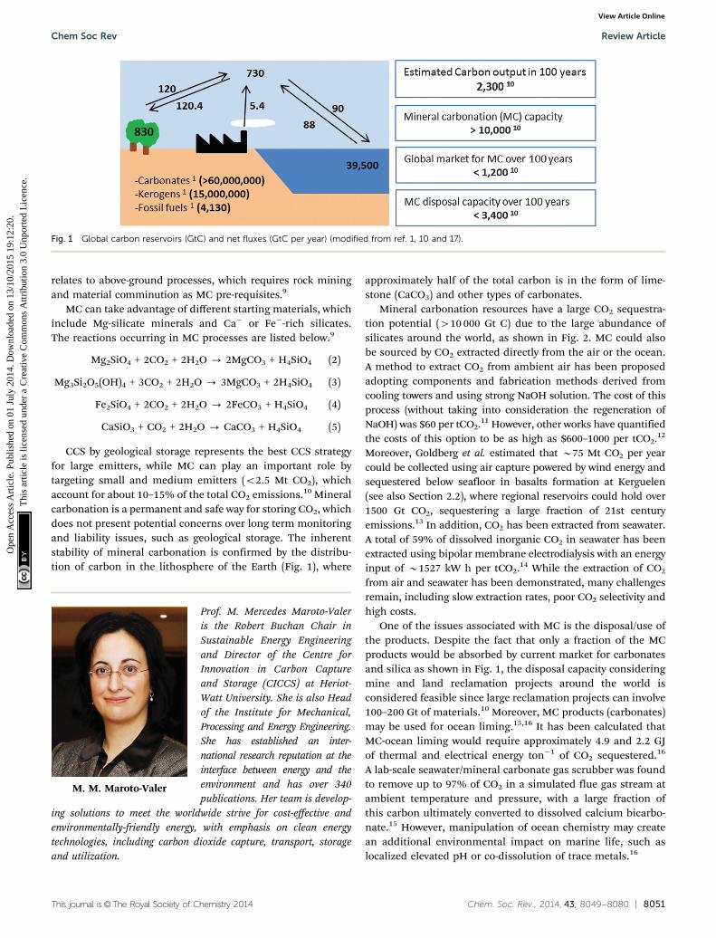
CCS by geological storage represents the best CCS strategyfor large emitters, while MC can play an important role bytargeting small and medium emitters (o2.5 Mt CO2), whichaccount for about 10–15% of the total CO2 emissions.10 Mineralcarbonation is a permanent and safe way for storing CO2, whichdoes not present potential concerns over long term monitoringand liability issues, such as geological storage. The inherentstability of mineral carbonation is confirmed by the distribu-tion of carbon in the lithosphere of the Earth (Fig. 1), where
approximately half of the total carbon is in the form of lime-stone (CaCO3) and other types of carbonates.
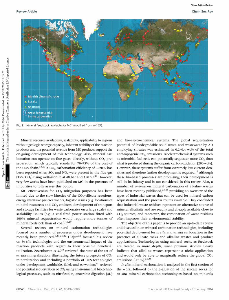
Mineral carbonation resources have a large CO2 sequestra-tion potential (410 000 Gt C) due to the large abundance ofsilicates around the world, as shown in Fig. 2. MC could alsobe sourced by CO2 extracted directly from the air or the ocean.A method to extract CO2 from ambient air has been proposedadopting components and fabrication methods derived fromcooling towers and using strong NaOH solution. The cost of thisprocess (without taking into consideration the regeneration ofNaOH) was $60 per tCO2.11 However, other works have quantifiedthe costs of this option to be as high as $600–1000 per tCO2.12
Moreover, Goldberg et al. estimated that B75 Mt CO2 per yearcould be collected using air capture powered by wind energy andsequestered below seafloor in basalts formation at Kerguelen(see also Section 2.2), where regional reservoirs could hold over1500 Gt CO2, sequestering a large fraction of 21st centuryemissions.13 In addition, CO2 has been extracted from seawater.A total of 59% of dissolved inorganic CO2 in seawater has beenextracted using bipolar membrane electrodialysis with an energyinput of B1527 kW h per tCO2.14 While the extraction of CO2
from air and seawater has been demonstrated, many challengesremain, including slow extraction rates, poor CO2 selectivity andhigh costs.
One of the issues associated with MC is the disposal/use ofthe products. Despite the fact that only a fraction of the MCproducts would be absorbed by current market for carbonatesand silica as shown in Fig. 1, the disposal capacity consideringmine and land reclamation projects around the world isconsidered feasible since large reclamation projects can involve100–200 Gt of materials.10 Moreover, MC products (carbonates)may be used for ocean liming.15,16 It has been calculated thatMC-ocean liming would require approximately 4.9 and 2.2 GJof thermal and electrical energy ton�1 of CO2 sequestered.16
A lab-scale seawater/mineral carbonate gas scrubber was foundto remove up to 97% of CO2 in a simulated flue gas stream atambient temperature and pressure, with a large fraction ofthis carbon ultimately converted to dissolved calcium bicarbo-nate.15 However, manipulation of ocean chemistry may createan additional environmental impact on marine life, such aslocalized elevated pH or co-dissolution of trace metals.16
Fig. 1 Global carbon reservoirs (GtC) and net fluxes (GtC per year) (modified from ref. 1, 10 and 17).
M. M. Maroto-Valer
Prof. M. Mercedes Maroto-Valeris the Robert Buchan Chair inSustainable Energy Engineeringand Director of the Centre forInnovation in Carbon Captureand Storage (CICCS) at Heriot-Watt University. She is also Headof the Institute for Mechanical,Processing and Energy Engineering.She has established an inter-national research reputation at theinterface between energy and theenvironment and has over 340publications. Her team is develop-
ing solutions to meet the worldwide strive for cost-effective andenvironmentally-friendly energy, with emphasis on clean energytechnologies, including carbon dioxide capture, transport, storageand utilization.
Chem Soc Rev Review Article
Ope
n A
cces
s A
rtic
le. P
ublis
hed
on 0
1 Ju
ly 2
014.
Dow
nloa
ded
on 1
3/10
/201
5 19
:12:
20.
Thi
s ar
ticle
is li
cens
ed u
nder
a C
reat
ive
Com
mon
s A
ttrib
utio
n 3.
0 U
npor
ted
Lic
ence
.View Article Online
8052 | Chem. Soc. Rev., 2014, 43, 8049--8080 This journal is©The Royal Society of Chemistry 2014
Mineral resource availability, scalability, applicability to regionswithout geologic storage capacity, inherent stability of the reactionproducts and the potential revenue from MC products support theon-going development of this technology. Also, mineral car-bonation can operate on flue gases directly, without CO2 pre-separation, which typically stands for 70–75% of the cost ofthe CCS chain.18,19 A CO2 carbonation efficiency of B20% hasbeen reported when SOx and NOx were present in the flue gas(15% CO2) using wollastonite at 40 bar and 150 1C.20 However,very few works have been published on MC in the presence ofimpurities to fully assess this option.
MC effectiveness for CO2 mitigation purposes has beenlimited due to the slow kinetics of the CO2–silicate reactions,energy intensive pre-treatments, logistic issues (e.g. locations ofmineral resources and CO2 emitters, development of transportand storage facilities for waste carbonates on a large scale) andscalability issues (e.g. a coal-fired power station fitted with100% mineral sequestration would require more tonnes ofmineral feedstock than of coal).10,17
Several reviews on mineral carbonation technologiesfocused on a number of processes under development haverecently been produced.8,17,21,22 Olajire21 focused his reviewon in situ technologies and the environmental impact of thereaction products with regard to their possible beneficialutilization. Zevenhoven et al.22 reviewed the state-of-the-art ofex situ mineralisation, illustrating the future prospects of CO2
mineralization and including a portfolio of CCS technologiesunder development worldwide. Salek and co-workers17 reviewedthe potential sequestration of CO2 using environmental biotechno-logical processes, such as nitrification, anaerobic digestion (AD)
and bio-electrochemical systems. The global sequestrationpotential of biodegradable solid waste and wastewater by ADemploying silicates was estimated in 0.2–0.4 wt% of the totalanthropogenic CO2 emissions. Bioelectrochemical systems suchas microbial fuel cells can potentially sequester more CO2 thanwhat is produced during the organic carbon oxidation (200 wt%).However, these systems suffer from extremely low current den-sities and therefore further development is required.17 Althoughthese bio-based processes are promising, their development isstill in its infancy and is not considered in this review. Also, anumber of reviews on mineral carbonation of alkaline wasteshave been recently published,23,24 providing an overview of thetypes of industrial wastes that can be used for mineral carbonsequestration and the process routes available. They concludedthat industrial waste residues represent an alternative source ofmineral alkalinity and are readily and cheaply available close toCO2 sources, and moreover, the carbonation of waste residuesoften improves their environmental stability.
The objective of this paper is to provide an up-to-date reviewand discussion on mineral carbonation technologies, includingpotential deployment for in situ and ex situ carbonation in thepresence of silicate rocks and alkaline wastes and productapplications. Technologies using mineral rocks as feedstockare treated in more depth, since previous studies clearlyindicate that alkaline wastes represent a niche applicationand would only be able to marginally reduce the global CO2
emissions (o1%).25,26
In situ mineral carbonation is analysed in the first section ofthe work, followed by the evaluation of the silicate rocks forex situ mineral carbonation technologies based on minerals
Fig. 2 Mineral feedstock available for MC (modified from ref. 27).
Review Article Chem Soc Rev
Ope
n A
cces
s A
rtic
le. P
ublis
hed
on 0
1 Ju
ly 2
014.
Dow
nloa
ded
on 1
3/10
/201
5 19
:12:
20.
Thi
s ar
ticle
is li
cens
ed u
nder
a C
reat
ive
Com
mon
s A
ttrib
utio
n 3.
0 U
npor
ted
Lic
ence
.View Article Online
This journal is©The Royal Society of Chemistry 2014 Chem. Soc. Rev., 2014, 43, 8049--8080 | 8053
and inorganic waste feedstocks. Finally, a section on thepotential products from mineralisation and final remarks ispresented.
2. In situ mineral carbonation
Carbonation is a natural process where CO2 reacts with differentminerals forming solid precipitates leading to the weathering ofthe rocks. The reactions are spontaneous and exothermic andcan be exemplified as (6) and (7) where calcium and magnesiumoxides are considered to react with CO2.
CaO + CO2 = CaCO3 + 179 kJ mol�1 (6)
MgO + CO2 = MgCO3 + 118 kJ mol�1 (7)
The most reactive compounds for CO2 mineralization areoxides of divalent metals, Ca and Mg, and their availabilityin nature is mainly in the form of silicates, such as olivine((Mg,Fe)2SiO4) orthopyroxene (Mg2Si2O6–Fe2Si2O6), clinopyroxene(CaMgSi2O6–CaFeSi2O6) and serpentine ((Mg, Fe)3Si2O5(OH)4),the latter originated by the hydratation of olivine. When CO2
dissolves in water, it reacts with these silicates forming corre-sponding carbonates, where CO2 is fixed in a mineral form.28,29
Mantle peridotite and basalts deposits, enriched in Mg, Feand Ca silicates, are the main targets for in situ CO2 miner-alization projects, as discussed below.21
2.1 Peridotites
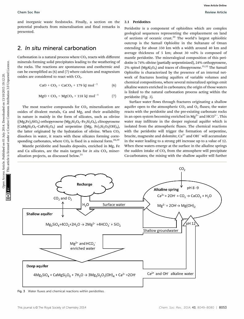
Peridotite is a component of ophiolites which are complexgeological sequences representing the emplacement on landof sections of oceanic crust.30 The world’s largest ophioliticoutcrop is the Samail Ophiolite in the Sultanate of Omanextending for about 350 km with a width around 40 km andaverage thickness of 5 km; about 30 vol% is composed ofmantle peridotite. The mineralogical composition of this peri-dotite is 74% olivine (partially serpentinized), 24% orthopyroxene,2% spinel (MgAl2O4) and traces of clinopyroxene.31,32 The SamailOphiolite is characterized by the presence of an internal net-work of fractures hosting aquifers of variable volumes andchemical compositions, where several mineralized springs emitalkaline waters enriched in carbonates; the origin of those watersis linked to the natural carbonation process acting within theperidotite (Fig. 3).
Surface water flows through fractures originating a shallowaquifer open to the atmospheric CO2 and O2 fluxes; the waterreacts with the peridotite and the pre-existing carbonate rocksin an open system becoming enriched in Mg2+ and HCO3�. Thiswater may infiltrate in the deeper regional aquifer which isisolated from the atmospheric fluxes. The chemical reactionswith the peridotite will trigger the formation of serpentine,brucite, magnesite and dolomite; Ca2+ and OH� will accumulatein the water leading to a strong pH increase up to a value of 12.When these waters emerge at the surface in the alkaline springsthe sudden intake of CO2 from the atmosphere will precipitateCa-carbonates; the mixing with the shallow aquifer will further
Fig. 3 Water fluxes and chemical reactions within peridotites.
Chem Soc Rev Review Article
Ope
n A
cces
s A
rtic
le. P
ublis
hed
on 0
1 Ju
ly 2
014.
Dow
nloa
ded
on 1
3/10
/201
5 19
:12:
20.
Thi
s ar
ticle
is li
cens
ed u
nder
a C
reat
ive
Com
mon
s A
ttrib
utio
n 3.
0 U
npor
ted
Lic
ence
.View Article Online
8054 | Chem. Soc. Rev., 2014, 43, 8049--8080 This journal is©The Royal Society of Chemistry 2014
precipitate Ca-carbonates and brucite. The formation of carbonates,mostly in the form of terraced travertine around the springs,consumes some OH� decreasing the pH to values of 8–9. The totalvolume of carbonate in the Samail Ophiolite is 5.5� 107 m3 with anaverage age of 26 000 years indicating that about 4� 107 kg CO2 peryear are consumed by the precipitation of carbonates. This naturalprocess requires long times for the reactions to develop, in the orderof magnitude of 50 years for the shallow-water aquifers and up to5600 years for the deep reservoirs. Artificial enhancement of thecarbonation can be achieved by injecting fluids with a higherconcentration of CO2 and increasing the temperature. For example,when injecting CO2 at 90 1C with 100 bar pCO2, about 0.63 kg of CO2
can be permanently stored as carbonates for each kg of peridotite.A typical in situ mineralization project in the Samail Ophiolite couldinclude the drilling of the peridotite, hydrofracturing of the hostingvolume, injection of heated fluids to increase the temperature at185 1C, which is the optimum temperature for olivine carbonationrates, followed by injection of pure CO2 at 25 1C. The exothermalreaction (producing 760 kJ kg�1) and the geothermal gradient (up to20 1C km�1) will both contribute to the reduction in the energyneeded for heating the fluids. The resulting enhancement ofthe carbonation rate following this process is considered to beone million times faster than the natural process pace.32,33
2.2 Basalts
The largest presence of basalts is on the oceanic crust.34 Largeoutcrops of basalts are also present on the continental crust.35
Basalts can have a good degree of secondary permeability dueto the formation of altered and brecciate horizons or networksof fractures during or after their deposition. The resulting porespace may be filled by circulating water originating fromaquifers within the hosting rocks at different depths andmineral concentrations. These aquifers are often enriched inions including Ca2+ and Mg2+,36 which can react with theinjected CO2 precipitating carbonates and releasing H+ as inreaction (8):
(Ca2+, Mg2+) + CO2 + H2O = (Ca, Mg)CO3 + 2H+ (8)
The reaction rate is controlled by the concentration of H+
and will not proceed further until these ions are neutralized by
the reaction with the hosting rock. Considering olivine andCa-plagioclase basalts the neutralization process follows reac-tions (9) and (10).
Mg2SiO4 + 4H+ = 2Mg2+ + SiO2 (9)
CaAl2Si2O8 + 8H+ = Ca2+ + 2Al3+ + 2SiO2(aq) + 4H2O (10)
The availability of reactive Mg, Al and Ca silicates is there-fore the controlling factor for the development of in situ CO2
mineralization.37
Following the injection of CO2 (both as supercritical fluidsor as aqueous solution) the dissolution of some minerals andthe precipitation of others, mostly carbonates, may change theporosity of the reservoir; carbonate deposition during the firststages of the injection may have adverse effects on the storagepotential due to the reduction in available pore space whichis progressively filled by minerals, and thus, clogging thesurrounding of the injection well. Mineral deposition in a moreadvanced phase of the injection and during the post-injectionphase instead is considered an advantage enhancing the trappingpotential of the hosting structure.
Injecting CO2 within the basalts of the ocean seafloor wouldbenefit from a further series of trapping mechanisms in addi-tion to the geochemical transformation of CO2 in carbonates.The deep water environment, below 2700 m, and the cold temper-ature, below 2 1C, will make the injected CO2 denser than thesurrounding seawater, allowing it to sink with a gravitation-trapping mechanism; the same environmental parameters arealso favourable to the formation of CO2 hydrates, where the CO2
molecule is ‘‘encaged’’ within a lattice of ice strongly reducingits solubility in water in the case of seepage. Lastly, the thicksedimentary cover of the seafloor will form a low-permeabilitylayer further reducing the possibility of leakage.38
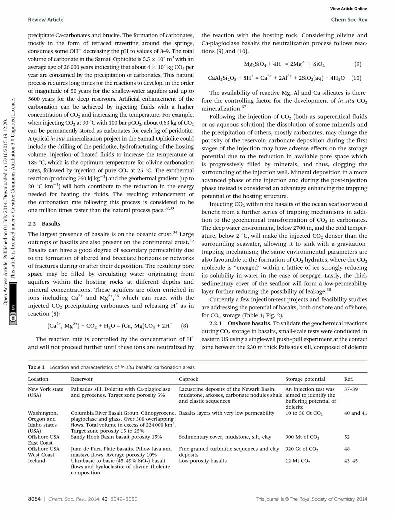
Currently a few injection-test projects and feasibility studiesare addressing the potential of basalts, both onshore and offshore,for CO2 storage (Table 1; Fig. 2).
2.2.1 Onshore basalts. To validate the geochemical reactionsduring CO2 storage in basalts, small-scale tests were conducted ineastern US using a single-well push–pull experiment at the contactzone between the 230 m thick Palisades sill, composed of dolerite
Table 1 Location and characteristics of in situ basaltic carbonation areas
Location Reservoir Caprock Storage potential Ref.
New York state(USA)
Palisades sill. Dolerite with Ca-plagioclaseand pyroxenes. Target zone porosity 5%
Lacustrine deposits of the Newark Basin;mudstone, arkoses, carbonate nodules shaleand clastic sequences
An injection test wasaimed to identify thebuffering potential ofdolerite
37–39
Washington,Oregon andIdaho states(USA)
Columbia River Basalt Group. Clinopyroxene,plagioclase and glass. Over 300 overlappingflows. Total volume in excess of 224 000 km3.Target zone porosity 15 to 25%
Basalts layers with very low permeability 10 to 50 Gt CO2 40 and 41
Offshore USAEast Coast
Sandy Hook Basin basalt porosity 15% Sedimentary cover, mudstone, silt, clay 900 Mt of CO2 52
Offshore USAWest Coast
Juan de Fuca Plate basalts. Pillow lava andmassive flows. Average porosity 10%
Fine-grained turbiditic sequences and claydeposits
920 Gt of CO2 48
Iceland Ultrabasic to basic (45–49% SiO2) basaltflows and hyaloclastite of olivine–tholeiitecomposition
Low-porosity basalts 12 Mt CO2 43–45
Review Article Chem Soc Rev
Ope
n A
cces
s A
rtic
le. P
ublis
hed
on 0
1 Ju
ly 2
014.
Dow
nloa
ded
on 1
3/10
/201
5 19
:12:
20.
Thi
s ar
ticle
is li
cens
ed u
nder
a C
reat
ive
Com
mon
s A
ttrib
utio
n 3.
0 U
npor
ted
Lic
ence
.View Article Online

This journal is©The Royal Society of Chemistry 2014 Chem. Soc. Rev., 2014, 43, 8049--8080 | 8055
with Ca-plagioclase (CaAl2Si2O8) and pyroxenes, and the under-lying sedimentary rocks of the Newark Basin composed oflacustrine deposits; mostly mudstone, arkoses, carbonate nodulesshale and clastic sequences. The estimated porosity of the targetzone is 5%. A fluid solution enriched in NaCl and KBr as tracersand equilibrated with CO2 at 8 bar and pH 3.5 was injected for3 hours in a 8 m thick section of dolerite; the total injected volumewas 1.4 m3 and was followed by a further 208 litres of tap waterused to flush the solution into the formation surrounding thewell. After 7 days the pull phase was started to collect samples.Within hours the pH returned to the initial value of 8.3; dissolu-tion of plagioclase and pyroxene within the groundwater wasmeasured as consequences of the fluid injection. From theseresults it was estimated that 1000 m3 of CO2 saturated water atPCO2
8 bar will be neutralized within 19 hours after the injection.Dissolution/precipitation processes and influence on the porosityof the reservoir are not totally understood yet.37,39
The Columbia River Basalt Group is a large continental floodbasalt deposit covering an area of more than 200 000 km2 inWashington, Oregon and Idaho states in the North-West US.Originated by a series of fissural eruptions between 17.5 and6.0 million years ago, it is composed of over 300 different flowswith a volume in excess of 224 000 km3. The flows can be dividedinto top and bottom areas, showing a vesicular and scoriaceouscrust often brecciated, and an inner massive core. The mineralcomposition is clinopyroxene, plagioclase and glass, the latterranging from a few percent to over 50%. The basalts host aregional deep aquifer of brackish water with high levels ofsulphide and fluoride exceeding the limits for drinking water;this aquifer is therefore the target for CO2 injection at a depthbetween 663 m and 887 m through a well drilled in the WallaWalla County in south-eastern Washington State. The hostingrocks are part of a top layer area with permeability in the range of75 to 150 md with 15 to 25% of porosity calculated fromuncalibrated sonic logs. The water chemistry of the injection areais of sodium-bicarbonate type with pH 9.68, fluoride 4.98 mg L�1
and Fe 962 mg L�1. In July 2013 a test injection of 1000 tCO2 wasstarted for one month. A model simulation forecasts that after oneyear 18% of CO2 will be dissolved in groundwater within a radiusof 55 m from the bore-hole. The storage capacity of the totalbasalt deposits for CO2 in situ mineralization is estimated from10 to 50 Gt CO2.40,41
Iceland has large volumes of basalt flows and hyaloclastites(volcanic breccias originated by the contact between the emittedlava and water or ice) associated with strong volcanic and geo-thermal activity with release of large volumes of CO2. There isevidence of natural carbonation processes within the aquifershosted in the basaltic deposits. The Hekla volcano in Icelandoriginated from linear eruptions during the last 900 years andrepresents the deposition of basaltic andesitic tephra largelycomposed of volcanic glass. The water feeding a series of springshas high alkalinity and pH ranging from 7.7 to 9.3; the variationin DIC (Dissolved Inorganic Carbon) within the spring water andits correlation with changes in pH is considered a proof that CO2
is fixed as carbonates. Another relevant aspect is that the heavymetals ions which can be mobilized from the rocks by the
acidification induced by the CO2 fluxes are incorporated incarbonates and oxy-hydroxides once the pH increases thusreducing the risk of environmental pollution.42
In Iceland the CarbFix project aims to assess the feasibilityof in situ carbonation in basalt using as the CO2 source thegas emitted from the geothermal power plant of Hellisheidi.The gas is associated with the geothermal steam and is composedof 83% CO2, 16% H2S and the remaining 1% as H2, N2, and CH4;the gas stream is condensed separating CO2 and H2S, which ismostly re-injected in the deep geothermal reservoir. The resultingfinal gas is composed of 98% of CO2 plus 2% of H2S and it is to beinjected in the deep basaltic aquifer. The hosting rocks areultrabasic to basic (45–49% SiO2) basalt flows and hyaloclastites(a breccia rich in volcanic glass) of olivine–tholeiite composition.Crystalline lava flows were in place after the last glacial age andthe hyaloclastites originated during the last glaciations underthe ice cover in a time span between 116 000 and 1500 yearsago. The resulting structure is a sequence of more permeable lavaflows hosting a shallow aquifer underlined by low-permeabilitylayers of hyaloclastites separating and isolating a deeper aquifer.The shallow aquifer (above 400 m) has a temperature of 8–12 1C,pH 7.7–8.4, CO2 in balance with the atmospheric values, it isenriched in O2 and it is undersaturated in calcite. The ground-water of the deep aquifer has temperature between 18 and 33 1C, apH of 8.4–9.4, CO2 concentration below the atmospheric balanceand it is depleted in O2 and saturated in calcite. This deep aquiferbetween 400 and 800 m is the target area for the storage in avolume of about 1 km3; CO2 will be dissolved in water at PCO2
of25 bar, pH 3.7, DIC 1 mol kg�1, requiring 22 t of water for each tonof CO2. A total of 2200 tCO2 per year will be injected. A monitoringprogram including geochemical analysis, tracers and isotopicconcentration measures will assess the diffusion of the injectedCO2 within the aquifer and the changes in chemistry associatedwith the mineralisation reaction. Models show that calcite pre-cipitation will reduce the porosity of the reservoir of about 1%.The total storage potential is of about 12 Mt CO2, or 200 yearsconsidering the annual emission from the geothermal plantin 60 000 tCO2.43–45
In 2011–2012 a test injection of 175 tons of pure CO2 and waterwas performed and in 2012–2013, 130 tons of CO2 mixed with H2Sfrom the power plant were injected in a low-temperature (20–50 1C)aquifer at 400–800 m of depth and in deeper reservoir (below 800 m)at higher temperature (4250 1C).46
2.2.2 Offshore basalts. In order to quantify the suitabilityof CO2 storage in submarine basalts some areas considered oflarge storage potential have been studied; their main charac-teristics are good porosity, the presence of sealing deposits atthe top and confined aquifers hosted within the formationwhere CO2 can dissolve. An example of such areas is the Juan deFuca Plate, offshore western USA, which is characterized bybasaltic bedrock of high average porosity (10–15%) composedof pillow lavas and massive flows covered by fine-grainedturbiditic sequences and clay sediments.47 The pillow lavasand the altered and fractured areas have the highest porosity,up to 20%; the massive flows show a much lower porosityranging between 2 and 9%. Hydrothermal fluids circulate
Chem Soc Rev Review Article
Ope
n A
cces
s A
rtic
le. P
ublis
hed
on 0
1 Ju
ly 2
014.
Dow
nloa
ded
on 1
3/10
/201
5 19
:12:
20.
Thi
s ar
ticle
is li
cens
ed u
nder
a C
reat
ive
Com
mon
s A
ttrib
utio
n 3.
0 U
npor
ted
Lic
ence
.View Article Online
8056 | Chem. Soc. Rev., 2014, 43, 8049--8080 This journal is©The Royal Society of Chemistry 2014
within the bedrock and are effectively contained by the sealingeffect of the overlying deposits allowing for long water-rockinteraction times and permitting chemical reaction with thesurrounding altered basalt. The target for CO2 injection is avolume of 7800 km3 of altered basalt with an average porosity of10% for a storage potential of 920 Gt of CO2.48
Another large accumulation of basalts is present along andoffshore the eastern coast of North America where it was origi-nated by a series of floods during subsequent eruptive eventsresulting in strata separated by alteration horizons with vesicularand brecciated layers.49 A series of deep sediments-filled basinshave been identified offshore and, both from geophysical data andcores, basalt layers have been identified below the sedimentarycover.50,51 These offshore basalts could represent a large storagevolume for the CO2 produced by point sources in the highlyindustrialized eastern shore belt of the USA.
As an example, the basalt present as bedrock of the SandyHook basin offshore New Jersey has an average porosity of 15%with an available pore volume for CO2 storage of about 1 km3
able to host 900 Mt of CO2, trapping of which will be enhancedby long-term mineral carbonation reactions.52
A general estimation of the overall potential storage capacityfor ocean basalts is 8238 Gt of CO2; this value is calculatedconsidering CO2 storage in brines hosted in 20 m thick horizonsof relatively porous (10% average porosity) pillow lavas and flowsat depth below 2700 m and overlaid by at least 200 m of oceansediments. The water depth and sedimentary cover enhance thegravitational, hydrate formation and low-permeability sealingtrapping mechanisms.53
3. Ex situ carbonation
Most processes under consideration for mineral carbonationfocus on metal oxide (such as calcium and magnesium) bearingmaterials, whose corresponding carbonates are not soluble. More-over, since waste materials rich in calcium oxide are convenientlylocated close to the CO2 emission source, they have also beentargeted as MC feedstock. The following sections will review theprocesses developed for both rocks and waste resources.
3.1 Processes developed for minerals
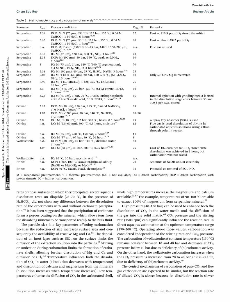
Since oxides and hydroxides of Ca and Mg are not abundant,silicate rocks containing the desired Mg and Ca have beentargeted for mineral carbonation.9 Table 2 summarises themain minerals available and their performance in terms ofmass ratio of ore necessary to carbonate the unit mass of CO2
(Rreal) and reaction efficiency (ECO2). Serpentine, olivine, and to
less extent wollastonite because of its lower abundance, arepreferred based on performance and availability.54
The sequestration of CO2 in carbonates can be achievedthrough various process routes, which are described in thissection: (1) direct carbonation (DC) is the simplest approach,where a Ca/Mg rich solid is carbonated in a single process step.DC can be further divided into gas–solid carbonation and directaqueous mineral carbonation. The direct aqueous mineral
carbonation-route with the aid of pre-treatments (DCP) is consid-ered as the state of the art and is typically selected to compare othertechnologies. (2) Indirect carbonation (IC) consists of first extract-ing from the feedstock the reactive Mg/Ca oxide or hydroxide in onestep and then, in a subsequent step, reacting the leached cationswith CO2 to form the desired carbonate.8
For each process carbonation route, key parameters of aprocess are presented in Table 3 to give quick insight into themain features. The parameters considered are the feedstockmaterial used; the mineral to CO2 ratio (Rreal); the mineral pre-treatment type (M-mechanical, C-chemical, T-thermal); opera-tional temperature and pressure; chemical additives used andfinally, the mineral cation reacted with CO2 (degree of conver-sion) (ECO2
%). The different direct and indirect processes arediscussed in detail in Section 3.1.2.
3.1.1 Process chemistry and reaction kinetics. The mainbarriers to the commercial deployment of carbonation are highenergy intensity, low reaction conversion and slow reactionkinetics.8,9 To reach the highest carbonation efficiency the con-trolling mechanisms and optimal parameters need to be defined.
The solid particle dissolution process is generally controlledby: (1) diffusion through a fluid film surrounding the particle,(2) diffusion through a solid product layer on the particlesurface, or (3) chemical reaction at the particle surface.55 Therate of the overall process is controlled by the slowest of thesesequential steps. Dissolution kinetics for olivine and serpentine,the two main source silicate minerals for mineral carbonation,have been studied for several decades; especially, olivine hasattracted noticeable interest.56–60
Dissolution of mineral is the rate-limiting step in the directaqueous mineral carbonation system, mainly due to theabsence of protons at pH close to 7.61–63 In an aqueous–solidreaction system, the rate-limiting step is the dissolution of themineral followed by product layer diffusion control (i.e. silicalayer reduces diffusion of CO2 or the carbonate precipitate).In CO2–water–solid systems, the reaction rate of CO2 dissolution(gas diffusion through fluid film control) is the limiting-controlstep.63 Despite the fact that dissolution rates of minerals arecommonly believed to be proportional to their crystals surface,the precipitation of secondary phases decreases the dissolution
Table 2 Mineral chemistry, carbonation potential, and reactivity (modifiedfrom ref. 54). (Carbonation test conditions: 80% �37 mm feed; 1 hour;185 1C; PCO2
= 150 atm; 15% solids; 0.64 M NaHCO, 1 M NaCl). Rreal = massratio of ore necessary to carbonate unit mass of CO2; ECO2
% = reactionefficiency, % stoichiometric conversion of Ca, Fe2+, and Mg cations insilicate feed to carbonate
Rock Mineral Mg Ca Fe2+ Rreal ECO2(%)
Serpentine Antigorite 24.6 o0.1 2.4 2.1 92Serpentine Lizardite 20.7 0.3 1.5 2.5 40Olivine Fayalite 0.3 0.6 44.3 2.8 66Olivine Forsterite 27.9 0.1 6.1 1.8 81Feldspar Anorthite 4.8 10.3 3.1 4.4 9Pyroxene Augite 6.9 15.6 9.6 2.7 33Basalt 4.3 6.7 6.7 4.9 15Oxide Magnetite 0.3 0.6 21.9 5.5 8Ultramafic Talc 15.7 2.2 9.2 2.8 15Ultramafic Wollastonite 0.3 31.6 0.5 2.8 82
Review Article Chem Soc Rev
Ope
n A
cces
s A
rtic
le. P
ublis
hed
on 0
1 Ju
ly 2
014.
Dow
nloa
ded
on 1
3/10
/201
5 19
:12:
20.
Thi
s ar
ticle
is li
cens
ed u
nder
a C
reat
ive
Com
mon
s A
ttrib
utio
n 3.
0 U
npor
ted
Lic
ence
.View Article Online
This journal is©The Royal Society of Chemistry 2014 Chem. Soc. Rev., 2014, 43, 8049--8080 | 8057
rates of those surfaces on which they precipitate; recent aqueousdissolution tests on diopside (25–70 1C, in the presence ofNaHCO3) did not show any difference between the dissolutionrate of the experiments with and without carbonate precipita-tion.64 It has been suggested that the precipitation of carbonateforms a porous coating on the mineral, which allows ions fromthe dissolving mineral to be transported readily to the bulk fluid.
The particle size is a key parameter affecting carbonationbecause the reduction of size increases surface area and con-sequently the availability of reactive Mg and Ca.65 The deposi-tion of an inert layer such as SiO2 on the surface limits thediffusion of the extraction solution into the particles.66 Stirringor sonication during carbonation limits the formation of carbo-nate shells, allowing further dissolution of Mg and Ca anddiffusion of CO2.65 Temperature influences both the dissolu-tion of CO2 in water (dissolution decreases with temperature)and dissolution of calcium and magnesium from the minerals(dissolution increases when temperature increases). Low tem-peratures enhance the diffusion of CO2 in the carbonated shell,
while high temperatures increase the magnesium and calciumavailable.65,67 For example, temperatures of 90–100 1C are ableto extract 100% of magnesium from serpentine mineral.68
High pressure (40–150 bar) can be used to enhance both thedissolution of CO2 in the water media and the diffusion ofthe gas into the solid matrix.69 CO2 pressure and the stirringrate (1500 rpm) can significantly influence the reaction rate indirect aqueous carbonation at the optimum temperature range(150–200 1C). Operating above those values, carbonation wasconsidered independent of the stirring rate and CO2 pressure.The carbonation of wollastonite at constant temperature (150 1C)remains constant between 10 and 40 bar and decreases at CO2
pressure below 10 bar due to deficiency of (bi)carbonate activity.On the other hand, the wollastonite carbonation increases whenthe CO2 pressure is increased from 20 to 40 bar at 200–225 1C,due to deficiency of (bi)carbonate activity.70
The control mechanisms of carbonation of pure CO2 and fluegas carbonation are expected to be similar, but the reaction rateof diluted CO2 is slower because its dissolution rate is slower
Table 3 Main characteristics and carbonation of minerals18,19,54,68,70,72,75–80,82,91,95,96,99–101,107–114,120–123,125
Resource Rreal Process conditions ECO2(%) Remarks
Serpentine 3.39 DCP: M, T (75 mm, 630 1C), 115 bar, 155 1C, 0.64 MNaHCO3, 1 M NaCl, 6 hours54,82
62 Cost of 210 $ per tCO2 stored (lizardite)
Serpentine 5.25 DCP: M, T (75 mm:630 1C), 115 bar, 155 1C, 0.64 MNaHCO3, 1 M NaCl, 1 hour95,96
80 Cost of about A$22 per tCO2
Serpentine n.a. DCP: M, T serp. (650 1C), 30–45 bar, 140 1C, 150–200 mm,NaHCO3
18,19,91n.a. Flue gas is used
Serpentine 3.33 IC: M (37 mm), 120 bar, 300 1C, NH3, 1 hour123 70Serpentine 2.33 DCP: M (100 mm), 50 bar, 550 1C, weak acid/NH3,
1 hour12590
Serpentine 3 IC: M (75 mm), 1 bar, 140 1C (300 1C regeneration),1.4 M NH4HSO4, NH3, 2–3 hours68,72
70
Serpentine 5.38 IC: M (100 mm), 40 bar, 65 1C, H2SO4, NaOH, 3 hours109 55Serpentine 5.83 IC: M, T (250–425 mm), 20 bar, 500–550 1C, (NH4)2SO4,
NH3, 0.5 hour120–12260 Only 50–60% Mg is recovered
Serpentine 8.97 IC: M, T (50 mm:150), 1 bar, 325 1C, HCl/NaOH,26 hours108
26
Serpentine 3.5 IC: M (o75 mm), 20 bar, 120 1C, 0.1 M citrate, EDTA,2 hours110,111
60
Serpentine 3.23 IC: M (75 mm), 1 bar, 70 1C, 1 vol% orthophosphoricacid, 0.9 wt% oxalic acid, 0.1% EDTA, 1 hour113,114
65 Internal agitation with grinding media is usedin the dissolution stage costs between 50 and100 $ per tCO2 stored
Olivine 2.22 DCP: M (38 mm), 150 bar, 185 1C, 0.64 M NaHCO3,1 M NaCl, 3 hours54,82
68
Olivine 1.82 DCP: M (o200 mm), 30 bar, 140 1C, NaHCO3,1–2 hours18,19
80–90
Olivine 2.8 DC: M, C (10 mm), 1.2 bar, 500 1C, bases, 0.5 hour76,77 25 A Spray Dry Absorber (SDA) is usedOlivine n.a. DC: M (2.5–60 mm), 500 1C, 0.5 hour, moisture75 12 Flue gas is used dissolution of olivine in
carbonated aqueous solutions using a flow-through column reactor
Olivine n.a. IC: M (75 mm), 250 1C, 150 bar, 2 hours107 11Olivine n.a. DC: M (37 mm), 97 bar, 80 1C, 20 hour78,79 8Wollastonite n.d. DCP: M (38 mm), 40 bar, 100 1C, distilled water,
1 hour54,8280
4.06 DC: M (38 mm), 20 bar, 200 1C, 0.25 hour70,80 75 Cost of 102 euro per ton CO2 stored 90%dissolution was achieved in 1 hour, butcarbonation was not tested
Wollastonite n.a. IC: 80 1C, 30 bar, succinic acid112 n.a.Brines n.a. DCP: 1 bar, 100 1C, seawater/brine/alkalinity
(NaOH or Mg(OH)2 or MgO)99,10070 Amounts of NaOH and/or electricity
Brines n.a. DCP: 30 1C, NaOH, NaCl, electrolysis101 98 Potential co-removal of SOx, NO2
M = mechanical pre-treatment; T = thermal pre-treatment; n.a. = not available; DC = direct carbonation; DCP = direct carbonation withpre-treatments; IC = indirect carbonation.
Chem Soc Rev Review Article
Ope
n A
cces
s A
rtic
le. P
ublis
hed
on 0
1 Ju
ly 2
014.
Dow
nloa
ded
on 1
3/10
/201
5 19
:12:
20.
Thi
s ar
ticle
is li
cens
ed u
nder
a C
reat
ive
Com
mon
s A
ttrib
utio
n 3.
0 U
npor
ted
Lic
ence
.View Article Online
8058 | Chem. Soc. Rev., 2014, 43, 8049--8080 This journal is©The Royal Society of Chemistry 2014
compared to that of pure CO2.71 The liquid/solid (L/S) ratio is animportant parameter because carbonation requires specific L/Sratios to be efficient.65 L/S-ratios lower than 2 cannot be stirredsufficiently in an autoclave reactor and may result in poor CO2
gas–liquid and solid–liquid mass transfer rates. Therefore, thelowest liquid-to-solid ratio in an autoclave reactor is 2 kg kg�1,although the majority of aqueous carbonation experiments arecarried out at a higher L/S-ratio to enhance the conversionefficiency.72 Also, the reduction of the L/S-ratio leads to a sub-stantial improvement of the heat balance of the process and,thus, the overall CO2 sequestration efficiency. However, if theL/S-ratio becomes too low, pumping and stirring problems mightarise because of an increased viscosity, which would lead to asignificant decrease of the conversion. Theoretically, an indus-trial process might be operated to 1 : 1 L/S ratios improving theoverall CO2 sequestration efficiency of the process.70
3.1.2 Direct carbonation (DC). DC consists of (1) gas–solidcarbonation and (2) aqueous carbonation.
3.1.2.1 Direct carbonation without pre-treatments. Gas–solidcarbonation: The most straightforward process route is the directgas–solid carbonation,73 and it was first studied by Lackner andco-workers.74 Various reactions depending on the feedstock arepossible. As an example, the direct gas–solid reaction of olivineis given:
Mg2SiO4(s) + 2CO2(g) = 2MgCO3(s) + SiO2(s) (11)
High CO2 pressures (100–150 bar) are necessary in order toobtain reasonable reaction rates.
DaCosta and co-workers75 developed a direct dry process forthe sequestration of CO2 where the flue gases pass through abed of finely ground (2.5–60 mm) silicate rocks (mainly olivine,serpentine or wollastonite). As carbonation takes place, themineral is replenished by either feeding fresh mineral with apump or a conveyer. They reported that when using 5 g ofolivine (surface of 2.5 m2 g�1) at temperature ranging from100 to 500 1C and flue composition of 10% CO2, 8.3% H2O(balanced with N2), the storage capacity was 0.12 g CO2 per golivine (12%) after 30 minutes.75 A higher capacity of 18% wasachieved capturing flue gas with 15% CO2 in the presence of8.3% water at 150 1C. The CO2 stored decreased when 5% or20% CO2 gas stream were used, in the absence of moisture andat the higher temperatures tested, 175 and 200 1C.76,77 Theenhanced CO2 stored capacity in the presence of moisture wasrelated to the fact that water vapour can be useful to convertoxides that may be present to hydroxides which may then becarbonated as in eqn (12) and (13):
MgO + H2O - Mg(OH)2 (12)
Mg(OH)2 + CO2 - MgCO3 (13)
The above process is able to work in a dry environment,where moisture present in flue gas is assumed to be enough toconvert the silicates oxides in the high reactive hydroxides andalso requires only B10–30 minutes, which represent a timescalable to the industrial level. However, it would require a
large amount of mineral per tonne of CO2 sequestered due tothe low efficiency (o20 g CO2 per g olivine).76 Based on the dataavailable, more than 8 tonnes of olivine would sequester 1 tonneof CO2. This would drastically reduce the applicability of thisprocess to very small CO2 emitters in terms of process size andmaterial handling. Also, particle size reduction to o60 mm isvery energy intensive.
Aqueous carbonation: the carbonic acid route process involvesCO2 reacting at high pressure (100–159 bar) in an aqueoussuspension with olivine or serpentine.61,69 Firstly, CO2 dissolvesin water and dissociates to bicarbonate and H+ resulting in a pHof about 5.0 to 5.5 at high CO2 pressure:
CO2(g) + H2O(l) = H2CO3(aq) = H+(aq) + HCO3�(aq) (14)
Mg2+ is then liberated from the mineral matrix by H+:
Mg2SiO4(s) + 4H+(aq) = 2Mg2+(aq) + SiO2(s) + 2H2O(l) (15)
Finally, Mg2+ reacts with bicarbonate and precipitates asmagnesite:
Mg2+(aq) + HCO3�(aq) = MgCO3(s) + H+(aq) (16)
Kwak and co-workers78,79 investigated the reaction pathwaysand reaction extent of direct aqueous carbonation of finelyground olivine (forsterite) (1 g) mixed with water (1 g) and fedinto a batch reactor with a volume of 11.7 mL. The reaction waskept at 80 1C and 97 bar for 20 h with a final CO2 storage capacityof 8%. The capacity was increased to 67% but it required 7 days.
Huijgen and co-workers80 studied the direct aqueous carbo-nation of finely ground wollastonite mineral to particle size38 mm that was suspended in distilled water. A CO2 stream wasintroduced into the reactor under continuous stirring to ensuredispersion of the gas. The carbonation reactions occur in theaqueous phase in two steps: calcium leaching from the CaSiO3
matrix and nucleation and growth of CaCO3. A promisingconversion of 75% was attained after 15 minutes at 200 1C,20 bar CO2 partial pressure, with estimated costs of 102 h pertCO2 sequestered, based on process simulation (Aspen). Themajor costs were associated with the feedstock and the elec-tricity consumption for grinding and compression, with 54 and26 h per tCO2 sequestered, respectively.70
Overall, direct routes present straightforward design and theabsence of non-aqueous solvents. However, reaction conver-sions are low and high CO2 pressure and temperature arerequired, compared to processes where pre-treatments are usedto enhance the CO2 storage capacity.73 To enhance reactionconversion, various pre-treatments have been employed.
3.1.2.2 Direct carbonation with pre-treatment. The purpose ofthe pre-treatment step is to promote and accelerate carbonationreaction rates and efficiencies through surface area increase. Twomajor processes have been developed: high energy mechanicalgrinding and chemical leaching, although other methods suchas thermal- and mechano-chemical-pretreatments have alsobeen reported.
Review Article Chem Soc Rev
Ope
n A
cces
s A
rtic
le. P
ublis
hed
on 0
1 Ju
ly 2
014.
Dow
nloa
ded
on 1
3/10
/201
5 19
:12:
20.
Thi
s ar
ticle
is li
cens
ed u
nder
a C
reat
ive
Com
mon
s A
ttrib
utio
n 3.
0 U
npor
ted
Lic
ence
.View Article Online

This journal is©The Royal Society of Chemistry 2014 Chem. Soc. Rev., 2014, 43, 8049--8080 | 8059
3.1.2.2.1 Direct carbonation with mechanical pre-treatment.The mechanical grinding approach aims at destroying or dis-ordering the mineral lattice, and thus, resulting in an increaseof the surface area. Particle size reduction takes place in asequence of crushing and grinding stages required to reducethe particle size to o300 mm which can be necessary to liberatevaluable mineral grains. Crushing is normally performed ondry materials using compression equipment such as jaw orcone crushers. Instead, grinding is accomplished by abrasionand impact of the ore by the free motion of unconnectedgrinding media such as rods, balls, or pebbles.81
The US National Energy Technology Laboratory (NETL)developed a direct carbonation process (scheme shown in Fig. 4),involving grinding of magnesium (or calcium) silicates at 150–200 1C, 100–150 bar, where 0.64 M NaHCO3 and 1 M NaCl wereadded to the solutions.54,82 NaHCO3 was used to turn to slightlyalkaline pH the solution in order to facilitate carbonate pre-cipitation. Olivine carbonation proceeded to over 80% in 6 h.Wollastonite was found to be the most reactive, reaching over70% in 1 h, and unlike the magnesium minerals, the wollastonitereaction proceeded rapidly in distilled water.82 The carbonationof olivine and wollastonite was controlled by the surface areaconsistent with the shrinking-core model, in which the particlesurface reacts to release magnesium into solution, leaving ashrinking core. The higher wollastonite efficiency was relatedto the much higher precipitation rate for CaCO3 comparedto MgCO3, which is four orders of magnitude lower than thoseof CaCO3.83
Various pre-treatment options such as ultrasonic treatmentand wet grinding in caustic solution have also been tested, butthey did not result in a higher reactivity.61 The major problemwith many other pre-treatment options is the high energy inputrequired.84 Extensive studies on the mechanical activation of
silicates were performed at NETL85,86 and were reviewed laterby Huijgen and Comans84 and Zevenhoven and co-workers.8
The major conclusions made were that high-energy attritiongrinding of silicates resulted in a higher conversion rates butconsumed too much energy.
Similar conclusions were obtained by Fabian et al.87 whostudied the CO2 storage capacity of olivine mechanically acti-vated using different conditions and by Haug et al.57 whoreported dissolution (in 0.1 M HCl, and pressured CO2/H2O)and carbonation (115–128 1C and under 150–185 bar) rates ofgrinded olivine. Activation in a planetary mill, even if effective,was found to consume too much energy (see Table 4) for CO2
sequestration purposes. Therefore, it can be concluded thatactivation methods, such as thermal and chemical activation(discussed in the following sections), are preferred options tomechanical activation.
3.1.2.2.2 Direct carbonation with thermal pre-treatment.As previously mentioned, serpentine requires additional thermal-treatment to remove hydroxyl groups, resulting in the chemicaltransformation to pseudo-forsterite. Serpentine requires heatingtreatment above 630 1C to remove chemically bound water fromthe lattice.89
Mg3Si2O5(OH)4 - (MgO)3(SiO2)2 + 2H2O (17)
The NETL findings indicate that the reaction rate forserpentine was slow if water (OH groups) was not removed.Thermally treated serpentine at 630 1C for 2 hours reached 65%CO2 storage capacity. Similar results were obtained with high-energy attrition grinding, but with a substantial associatedenergy penalty.54,82 The theoretical energy required for the heat-activation process is the sum of the energy to heat the mineral to630 1C and the enthalpy of dehydroxylation. As shown in Table 4,this energy (as electrical power) was quantified in 293 and326 kW h per t for antigorite and lizardite, respectively.54 Otherauthors have performed thermal-treatment optimisation stu-dies.90–94 Sanna et al.94 reported that the energy requirementfor 0.5 h activation at 610 1C could be lowered to 245 kW h per tinstead of 326 kW h per t previously reported (630 1C for 2 h).This enhanced the subsequent dissolution of serpentine from60% to 90% in just 5 minutes, where the Mg extracted washigher compared to another recent work where thermal activa-tion was performed at 640–700 1C for 1 h.92
The direct use of thermal heat instead of electrical energy,coupled to partial dehydroxylation with heat integration (63%decrease in energy requirement for thermal-activation), has ledto an overall mineral carbonation process estimated cost of A$70 per tCO2 avoided,91,93 compared to $ 210 per tCO2 avoidedin the NETL process.82 Balucan et al.93 studied the thermalactivation of serpentine from the Great Serpentinite Belt in NewSouth Wales (Australia), in a Thermo-Gravimetric Analysis-Differential Scanning Calorimetry (TGA-DSC) apparatus. Thisserpentine was found to be particularly suitable for heat activa-tion to 20% residual hydroxyl groups, as opposed to the partlyserpentinised ultramafic minerals of the Coolac SerpentiniteBelt. The activation strategy comprised heating serpentine
Fig. 4 Scheme of the NETL process (modified from ref. 82).
Chem Soc Rev Review Article
Ope
n A
cces
s A
rtic
le. P
ublis
hed
on 0
1 Ju
ly 2
014.
Dow
nloa
ded
on 1
3/10
/201
5 19
:12:
20.
Thi
s ar
ticle
is li
cens
ed u
nder
a C
reat
ive
Com
mon
s A
ttrib
utio
n 3.
0 U
npor
ted
Lic
ence
.View Article Online
8060 | Chem. Soc. Rev., 2014, 43, 8049--8080 This journal is©The Royal Society of Chemistry 2014
particles with diameter o 34 mm to 680 1C (1.5 h) to produce anactive material with 20% residual hydroxyl groups and therecovery of B80% of the sensible heat from the dehydroxylatedmineral. This results in a thermal activation estimated cost ofA$ 1.25 per t of serpentine.93 Serpentine from Coolac SerpentiniteBelt used in the experiments had a much larger particle size(D90 127 mm) so the comparison is rather difficult. Also, particlessize reduction to o34 mm is energy intensive (4220 kW h per t).82
However, if these preliminary studies are confirmed,91 techno-logies that use thermal-pretreatment may become more attractive,although they may be constrained by the specific reactivity of theserpentine used. Overall, on the data available, thermo-treatmentis more effective in accelerating the Mg extraction than mechan-ical activation, although its associated energy penalty still remainssignificantly high.87,94
3.1.2.2.3 NETL derived processes. Brent and co-workersexplored a better use of the system heat in order to avoidthe drawbacks of serpentine thermal-chemical activation.95 Theprocess is being exploited by Orica, a large Australian companyinterested in mineral carbonation. The energy savings wereobtained after preheating the mineral feedstock in a combinedseries of heat exchangers utilising the exothermic heat from thecarbonation reactor and low grade heat from the same powerplant that provides the flue gas. The proposed mineral carbo-nation plant does not include CO2 capture and serpentinemining. Serpentine was reduced to a particle size of less than75 mm. Since the recovered low grade heat from carbonation(120–150 1C) and power plant was not enough to reach thedesired activation temperature (4580 1C), a hydrocarbon-aceous fuelled furnace was used for the last heating step. Thesame chemical additives as in the NETL process were used.Carbonation was carried out at pressure in excess of 150 bar.This process has been claimed to be economically viable (Aspenmodelling) for the permanent storage of 14.1 Mt per year of CO2
emissions from a conventional pulverised fuel electricity gen-eration plant (15 500 GW h per annum), which would consumeabout 41 Mt per year of serpentine and an additional 0.9 Mt peryear coal to activate the serpentine at a claimed cost of aboutA$22 per tCO2.95,96 However, for the process neither experi-mental nor simulation work has been reported so far and itpresents a very high grade of process integration, which may bedifficult to achieve. Moreover, it does not consider some logisticissues, such as the long distance location of mineral and CO2
point sources.Shell has developed an aqueous slurry-based mineralisation
technology suitable for both serpentine and olivine mineralrocks. The process comprises pre-treatment, leaching and pre-cipitation steps, where activation of serpentine is achieved byboth mechanical and thermal means.18,19 The overall processresembles that developed by NETL, but operates under lowerprocess conditions. The slurry from the leaching step is pres-surised (up to 45 bar) and heated up to 110–140 1C in theprecipitation step. Here, precipitation of dissolved Mg(HCO3)2
takes place as well as transformation of hydromagnesite intomagnesite. Two different concepts have been proposed as shownT
able
4E
ne
rgy
con
sum
pti
on
for
min
era
lfe
ed
sto
ckp
re-t
reat
me
nts
.82
,87,8
8(3
06
)e
ne
rgy
con
sum
pti
on
incl
ud
ing
me
chan
ical
pre
-tre
atm
en
t
Mec
han
ical
acti
vati
on(o
livi
ne)
RPM
Tim
e(m
in)
SA(m
2g�
1)
Cry
stal
lin
eph
ase
(%)
En
ergy
con
sum
ptio
n(k
Wh
per
t)
As-
rece
ived
——
0.25
100
—15
0010
7.3
4519
0A
ttri
tor
3018
.126
580
120
35.2
1223
10Pl
anet
ary
450
104.
837
2010
305.
217
6030
Nu
tati
ng
900
103
5764
0A
ttri
tor
1500
107.
3n
.a.
170
Att
rito
r15
0030
18.1
n.a
.52
0A
ttri
tor
1500
120
35.2
n.a
.20
80
Th
erm
alac
tiva
tion
(ser
pen
tin
e)C
arbo
nat
ion
effici
ency
(%)
En
ergy
con
sum
ptio
n(k
Wh
per
t)
An
tigo
rite
(75mm
)62
293
(306
)A
nti
gori
te(3
8mm
)92
293
(376
)Li
zard
ite
(75mm
)9
326
(339
)Li
zard
ite
(38mm
)40
326
(409
)
Review Article Chem Soc Rev
Ope
n A
cces
s A
rtic
le. P
ublis
hed
on 0
1 Ju
ly 2
014.
Dow
nloa
ded
on 1
3/10
/201
5 19
:12:
20.
Thi
s ar
ticle
is li
cens
ed u
nder
a C
reat
ive
Com
mon
s A
ttrib
utio
n 3.
0 U
npor
ted
Lic
ence
.View Article Online
This journal is©The Royal Society of Chemistry 2014 Chem. Soc. Rev., 2014, 43, 8049--8080 | 8061
in Fig. 5, namely Shell’s direct pure and flue gas mineralizationtechnology (Fig. 5a and b). Since flue gas with 10% vol CO2 has amuch lower solubility than pure CO2 under pressure, leaching ofcations in the presence of CO2 will take place at a much slowerrate. To avoid this, the flue gas is brought into contact with themineral slurry prior to the precipitation stage in a separate slurrymill at ambient temperature.19 The slurry mill achieves both ahuge reduction of particle size and the formation of carbonateintermediates other than bicarbonate, for instance hydromagne-site. Shell’s thermal activation, which can reduce energy require-ment up to 63%, has been employed in this process.91 It consistsof heating the serpentine (preferably 150–200 mm) for 1 hour at atemperature of 650 1C in a fluidised bed. No data on the CO2
sequestration capacity and energy consumption are publicallyavailable. Technical feasibility of Shell’s proposed direct flue gasmineralization concept using activated serpentine has beenproved at the Energy Centre of the Netherlands (ECN) in acontinuous pilot plant. The continuous experiments show thatseawater accelerates the rate of leaching and subsequent pre-cipitation, but requires particular material choice as expected.Also, it was shown that yielding dissolved magnesium bicarbo-nate by not using a magnesium carbonate precipitation unit hasa large cost advantage, resulting in about 80% cost reduction. Onthe basis of the information available, the proposed processseems to be able to decrease the energy requirements for theserpentine pre-treatment, compared to the NETL process byemploying proprietary thermo-treatment technology, but noinformation on potential costs is available yet. This technologywould not get any benefit from the resultant products, since theyare mixed in slurry, which would require energy intensiveprocessing to isolate them.
3.1.2.2.4 Brine-based processes. A different approach hasbeen developed by Calera, which owns a demonstration plantat the gas fired Moss Landing power plant (USA). The MossLanding plant has demonstrated to capture flue gas CO2 from a
10 MW power generator at 90% efficiency for about 2 years.96,97
A diagram of the Calera process is depicted in Fig. 6. Thetechnology foresees the introduction of brines containing alka-line earth metal ions into a reactor, where the brine is contactedwith CO2 containing gas. CO2 dissolves in water to producecarbonate and bicarbonate ions, resulting in a decrease in thepH of the solution. In order to produce a carbonate-containingprecipitate, protons are removed from the solution so as to shiftthe equilibrium towards carbonate (which requires pH 9–11 toprecipitate). The solution pH is then increased through theintroduction of alkalinity to the point where the alkali metalsare precipitated as carbonates, which may be suitable for cementmanufacture. A 20% replacement in blended cement appearedto be technically feasible, but not yet demonstrated.98 An energypenalty ranging from about 10% to 40%, depending on powerplant characteristics and availability of brines, has been asso-ciated with this process.98
Besides the fact that a large number of brines containingalkaline earth metal ions (Ca, Mg) are mentioned as potentialfeedstocks,99,100 the technical suitability of brines (e.g. initialproposal of using brines at the Latrobe Valley demonstrationproject was abandoned because of technically unsuitable brines),sea water and alkaline waste for the Calera process (design at theMoss Landing California pilot plant concluded that sea waterrequired too much energy and alkaline industrial waste would betoo limited for sustainable operations at a significant scale)reduces the wide application of this technology.98
Fig. 6 provides a scheme of the Calera process, where the finalproduct is a cementitious material with the consistency of mud,which when de-watered, becomes an aggregate-like solid.98
Another method of sequestering carbon dioxide usingbrines, referred to as SkyMine, has been recently proposed.101
CO2 is absorbed into an aqueous caustic soda mixture to formcarbonate and/or bicarbonate products.101 Flue gas from thepower plant is cooled from 300 1C to 30 1C in a series of heatexchangers and then it is introduced at the bottom of an
Fig. 5 Mineralization process concept for pure CO2 and flue gas (modified from ref. 19).
Chem Soc Rev Review Article
Ope
n A
cces
s A
rtic
le. P
ublis
hed
on 0
1 Ju
ly 2
014.
Dow
nloa
ded
on 1
3/10
/201
5 19
:12:
20.
Thi
s ar
ticle
is li
cens
ed u
nder
a C
reat
ive
Com
mon
s A
ttrib
utio
n 3.
0 U
npor
ted
Lic
ence
.View Article Online

8062 | Chem. Soc. Rev., 2014, 43, 8049--8080 This journal is©The Royal Society of Chemistry 2014
absorber, where NaOH is used. The latter is produced by brineelectrolysis. The reaction taking place in the carbonationchamber is:
2NaOH + CO2 = Na2CO3 + H2O and Na2CO3 + H2O + CO2
= 2NaHCO3 (18)
The carbonate and bicarbonate formed are separated fromthe liquid solution by heating, which can be done by exchangeof heat with the flue gas (93% purity of Na2CO3 is achieved) orheat derived from hydrogen produced in electrolysis. In themembrane cell processing units, the following inputs andproducts are obtained:
At the anode: 26% NaCl + 2275 kW h per tCl2 = Cl2(g) + 24%
NaOH (19)
At the cathode: H2O + e = 30–33% NaOH + H2(g) (20)
This process claims to reach a conversion of 98% by usinglarge amounts of NaOH and/or electricity.101 In addition tocapturing and mineralizing CO2, the SkyMine process alsoclaims the possibility to clean SOx and NO2 from the flue gas,and remove heavy metals, such as mercury. A joint venturenamely Skyonic Corporation, which includes BP and Conoco-Phillips, has started the construction of a commercial CO2
capture plant to remove 83 000 tCO2 per year from a cementplant (130 000 considering the reduced emissions in producingbacking soda). The strength of the process is represented bythe possibility to produce valuable carbon-negative products(e.g. hydrochloric acid and sodium bicarbonate) using low-cost chemical inputs in a low energy requirement capture-mineralisation plant.102 Despite the fact that the reliability ofthe process has been proved and large investment has beenreceived ($128 millions), a comprehensive cost assessment isnot publically available. Also, it has to be noticed that marketfor HCl and sodium bicarbonate is not large for a wideapplication of this technology.
3.1.2.2.5 Organic acid direct processes. Organic acids andtheir anions may affect mineral weathering rates by three possiblemechanisms: (1) changing the dissolution rate far from equili-brium either decreasing solution pH or forming complexes withcations at the mineral surface, which provides a new parallelreaction mechanism for the detachment of material from themineral surface; (2) ability to make aqueous complexes withaqueous metals that would otherwise inhibit rates; and (3)changing the ions speciation in solution, which affects thedissolution rate of minerals.103,104 Far from equilibrium, thedissolution rates of most silicate minerals increase exponen-tially with increasing hydrogen ion concentration (low pH) insolution. The pH effect can be explained by the fact that sorptionof protons on an oxide surface polarizes the metal–oxygen bonds,weakening the bonding with the underlying lattice.103
Recently, Bonfils et al.62 have proposed a direct mineralcarbonation process where organic acids are used to enhancethe dissolution of silicate rocks. The interactions betweenorganic ligands and magnesium silicates have been reportedin the geochemical literature since organic acids are moreefficient than water in accelerating silicate leaching dissocia-tion of Mg–O–Si bonds in the presence of protons.59,105 Bonfilswork showed that the presence of disodium oxalate under20 bar of CO2 pressure leads to the formation of strong oxalate–magnesium complexes in solution and precipitation of MgC2O4�2H2O (glushinskite), which impede the precipitation of magne-sium carbonate. Contrary to oxalate, citrate and EDTA saltsligands do not form any solid by-products with magnesium, butalso do not promote carbonation, arising strong doubts on thepossibility of developing a direct aqueous mineral carbonationprocess using organic salts.62 Moreover, Declercq et al.104 investi-gated the effect of organic ligands on olivine (forsterite) dissolutionat 25 1C and pH 3. The study included the evaluation of acetate,oxalate, citrate, EDTA, glutamate, gluconate, malonate, aspartate,tartrate, malate, alginate, salicylate and humate. Their study, inagreement with previous reports, concluded that aqueous organicligands have at most a small effect on forsterite dissolution rates
Fig. 6 Calera process diagram (modified from ref. 98).
Review Article Chem Soc Rev
Ope
n A
cces
s A
rtic
le. P
ublis
hed
on 0
1 Ju
ly 2
014.
Dow
nloa
ded
on 1
3/10
/201
5 19
:12:
20.
Thi
s ar
ticle
is li
cens
ed u
nder
a C
reat
ive
Com
mon
s A
ttrib
utio
n 3.
0 U
npor
ted
Lic
ence
.View Article Online
This journal is©The Royal Society of Chemistry 2014 Chem. Soc. Rev., 2014, 43, 8049--8080 | 8063
under strongly acidic conditions but may have an effect at higherpH (4–7).
The contrasting effects of organic acids on steady-stateforsterite dissolution rates with increasing pH were related totheir aqueous speciation, since these organic species are in theform of neutral species at acidic pH, but as negatively chargedaqueous species under mild acidic and neutral conditions.104
3.1.3 Indirect carbonation. Indirect mineral carbonationrefers to processes that take place in more than one stage.Indirect carbonation typically involves the extraction of reactivecomponents (Mg2+, Ca2+) from minerals, using acids or othersolvents, followed by the reaction of the extracted componentswith CO2 in either the gaseous or aqueous phase. Pure carbo-nates can be produced using indirect methods, due to removalof impurities in previous carbonate precipitation stages.23,106
Munz et al.107 demonstrated the principles of separatingmagnesite and silica after dissolution of olivine in carbonatedaqueous solutions using a flow-through column reactor. Theprocess consisted of three steps: (1) dissolution of 75 mm fineolivine at 130 1C and 150 bar; (2) precipitation of magnesite at250 1C; and (3) precipitation of silica. Both precipitation stepswere dependent on pH and temperature.107 A carbonationefficiency of 11% and 93% was obtained after mechanicalpre-treatment (211 kW h per t) after 2 and 18 hours, respec-tively.60 However, as high carbonation efficiency was onlyobtained after long times, the process is not viable on anindustrial scale.
A wide number of strong acids and bases such as HCl,H2SO4 and HNO3 have been employed for the dissolution ofsilicate rocks.2,23,56,108 Lin et al.108 proposed a 2-stage process,where serpentine is decomposed to magnesium hydroxideusing HCl at 150 1C. The resulting Mg(OH)2 was then carbo-nated at 325 1C for 2 hours in a fixed bed at atmosphericpressure.108 However, because the authors did not address therecovery of the chemicals used in the process and the timerequired for dissolution was too long compared to the precipi-tation stage, the process was not attractive. Maroto-Valeret al.109 developed a process, where serpentine was chemicallyactivated with H2SO4 at a temperature 20–65 1C for 3–12 hours.The resulting magnesium sulphate was reacted with sodiumhydroxide to precipitate Mg(OH)2 following an exothermicreaction. Mg(OH)2 subsequently reacted with CO2 in aqueoussuspension at 20 1C and 40 bar. A conversion of 55% wasachieved in 10 minutes under these mild conditions. Sulphuricacid was regenerated by reacting CO2 with MgSO4.109 However,chemicals make up and intensive chemical regeneration hinderedthe deployment of this process. The effect of HCl, H2SO4 andHNO3 on serpentine dissolution at 20 1C and different solutionconcentrations (1, 2, and 4 M) revealed that their capacity indissolving the mineral decreases in this order: H2SO4 4 HCl 4HNO3. Despite their effectiveness in extracting Mg from silicates,processes that employed strong acids did not result in viable MCprocesses due to the overall difficult and large energy penaltiesassociated with their recovery.2,56 Organic acids have also beeninvestigated in mineral carbonation to reduce the energy penaltyassociated with strong acids. Teir et al.56 found that acetic acid
(CH3COOH) and formic acid (HCOOH) were able to leach asignificant amount of magnesium from serpentine. Krevor andLackner110 established that the sodium salts of citrate, oxalate,and ethylenediaminetetraacetic acid (EDTA) significantly enhancethe dissolution of serpentine under weakly acidic conditions.In their process, finely ground serpentine of particle size lessthan 75 mm was reacted in a solution with dissolved salts undera CO2 atmosphere and at 120 1C.110,111 This energy penalty canbe avoided dissolving the serpentine at an essentially neutralpH, i.e. in a solution more weakly acidic than carbonic acid.The reactions rates were several orders of magnitude higher inthe presence of citrate than in the weakly acidic solution alone.Carbonation was performed at 20 bar and 120 1C. After 2 hoursa conversion of 60% was achieved, while 80% was reached after7 hours. EDTA, which forms magnesium complexes severalorders of magnitude more stable than oxalate and citrate,cannot be used as a catalyst.110,111 The recovery and regenera-tion of the additive salts were not addressed in this work, whichrepresents a major limit for its potential evaluation, as in thecase of strong acids. Also, the long reaction times at the highestCO2 conversion would require a very large plant footprint to beeconomic. Succinic acid was also employed to extract reactivecomponent (Ca2+) from wollastonite at 80 1C and 30 bar.A promising calcium dissolution of 90% was achieved after1 hour, but the carbonation step was not tested.112 Park et al.113,114
demonstrated that a mixture of 1 vol% orthophosphoric acid,0.9 wt% oxalic acid and 0.1% EDTA greatly enhanced theleaching of magnesium from serpentine at 70 1C and 1 bar.After 1 hour dissolution, the slurry was filtered to remove theSiO2 residue. The use of internal agitation with grinding mediain the dissolution stage greatly improved the extraction ofmagnesium from serpentine. The filtrate rich in Mg2+ andFe2+ was then carbonated by bubbling through CO2 at ambienttemperature. Overall, the conversion achieved was 65%, butrecovery of additives was not addressed even in this case.113,114
With the aim of improving the efficiency of mineral dissolu-tion and recovering and re-using additives, Maroto-Valer andco-workers proposed a pH-swing CO2 mineralisation processusing ammonium salts.68 At 100 1C, 1.4 M aqueous solutionNH4HSO4 was found to extract 100% Mg from serpentine in3 hours. The proposed process consists of five steps and themain reactions are presented in Fig. 7. In the first step, NH3
was used to capture CO2 from flue gas to produce NH4HCO3. Inthe mineral dissolution step, 1.4 M NH4HSO4 was used toextract Mg from serpentine ground to a particle size range75–125 mm. The Mg-rich solution was then neutralised byadding NH4OH, after which impurities in the leaching solutionwere removed by adding NH4OH. The Mg-rich solution is thenreacted with the product from the capture step NH4HCO3 toprecipitate carbonates. Since the formation and stability ofhydro-carbonates is temperature dependent, MgCO3�3H2O(nesquehonite) can be converted to 4MgCO3�Mg(OH)2�4H2O(hydromagnesite) at temperatures above 70 1C. Precipitationof hydromagnesite resulted in a solution mainly containing(NH4)2SO4. The final step was the additive regeneration, withthe decomposition of (NH4)2SO4 at B330 1C, and producing
Chem Soc Rev Review Article
Ope
n A
cces
s A
rtic
le. P
ublis
hed
on 0
1 Ju
ly 2
014.
Dow
nloa
ded
on 1
3/10
/201
5 19
:12:
20.
Thi
s ar
ticle
is li
cens
ed u
nder
a C
reat
ive
Com
mon
s A
ttrib
utio
n 3.
0 U
npor
ted
Lic
ence
.View Article Online

8064 | Chem. Soc. Rev., 2014, 43, 8049--8080 This journal is©The Royal Society of Chemistry 2014
NH3 for the capture step and NH4HSO4 for the dissolutionstep.68,72
In a typical capture process, CO2 is first absorbed bychemicals (e.g. NH3) and then desorbed (to recover the sorbent)and compressed for transportation, where stripping and com-pression consumes about 70% of the total CCS energy consump-tion. Since CO2 captured as sodium carbonate/bicarbonate isdirectly used in the proposed mineral carbonation, there is noneed for desorption and compression of CO2. This process asother pH swing processes is also able to separate three differentproducts: silica, magnesite and iron oxide.56,66,68,106,114 Thisprocess could also be integrated with the chilled ammoniaCO2 capture process, which has been demonstrated to capturemore than 90% of CO2 (from 3–15% CO2 in flue gas)115 and anestimated energy penalty of 477 kW h per tCO2.116
The main drawback of the aqueous pH swing ammonium-based process is represented by the large amount of water thatneeds to be separated from the salts during the regeneration step.
Based on their work, where a solid to liquid (S/L) ratio or 50 g L�1
was used, 50–56 tH2O were required to sequester 1 tCO2. Sincewater evaporation is a high energy penalty process, they attemptedto reduce the water usage in the system.117 When the S/L ratioincreased to 300 g L�1, 16 tH2O were required to sequester 1 tCO2.However, since the CO2 fixation efficiency decreased to 46.6%, alarger amount of reactants (serpentine and salts) were required.Moreover, the amount of water to be evaporated is still too highand alternative separation methods need to be investigated inorder to make this process economically feasible.
A two-step process which also uses ammonium salts has beenrecently developed by Zevenhoven and co-workers.118,119 Thescheme of this process is shown in Fig. 8. In the first step,Mg(OH)2 was produced from serpentinite and in the secondstep, Mg(OH)2 was carbonated in the dry phase. This processtakes advantage of: (1) the higher reactivity of Mg(OH)2 com-pared to that of serpentinite and MgO and (2) the potentialrecovery of the heat of reaction released during the carbonation.
Fig. 7 pH-swing CO2 mineral carbonation process with recyclable ammonium salts (modified from ref. 68).
Fig. 8 Åbo Akademi mineral carbonation process (modified from ref. 121).
Review Article Chem Soc Rev
Ope
n A
cces
s A
rtic
le. P
ublis
hed
on 0
1 Ju
ly 2
014.
Dow
nloa
ded
on 1
3/10
/201
5 19
:12:
20.
Thi
s ar
ticle
is li
cens
ed u
nder
a C
reat
ive
Com
mon
s A
ttrib
utio
n 3.
0 U
npor
ted
Lic
ence
.View Article Online

This journal is©The Royal Society of Chemistry 2014 Chem. Soc. Rev., 2014, 43, 8049--8080 | 8065
In the Mg extraction step, a mixture of serpentinite was heatedtogether with ammonium sulphate at a temperature of 450–550 1C. This resulted in the formation of magnesium sulphate,which was then dissolved in water. Adjusting the pH usingammonium hydroxide or ammonia led to precipitation ofMg(OH)2, while iron oxide was recovered as the by-product.Finally, Mg(OH)2 was carbonated in a fluidised bed at 20 bar and500–550 1C. A 50% Mg conversion was achieved in 10 minutes.120
With this work, the authors attempted to reduce the high energyrequirements for the regeneration steps of aqueous pH swingprocesses (water/salts separation by thermal evaporation) and alsoattempted the recovery of the carbonation heat. Although it isthermodynamically feasible to recover heat of reaction in theexothermic carbonation stage for the endothermic magnesiumextraction, this has not yet been practically demonstrated. More-over, modest recovery of magnesium (50–60%) is currently limitingthis technology.121 Mg extraction from serpentine is carried outusing ammonium sulphate acidic derivatives (ammonium bisulfateand sulfamic acid are formed at temperature 4300 1C). However,sulfamic acid volatilizes and/or decomposes at a significant rate by400 1C, which will affect the recovery of Mg.121,122
Hunwick123 developed a multistep method for captureand sequestration of CO2 from power station flue gases. Thisprocess is being developed by an Australian company, Inte-grated Carbon Sequestration Pty Ltd, after the proof-of-conceptexperiments carried out at Commonwealth Scientific andIndustrial Research Organisation (CSIRO). In the first step,finely grinded (o40 mm) Mg/Ca silicates were mixed withammonia to produce an aqueous slurry of 30% solids. Then,CO2 was absorbed into the slurry, which was pumped to areactor at an elevated pressure of 100 bar and at a temperatureof 225 1C so as to enhance the rate of a reaction between CO2
and serpentine. Magnesium carbonate was produced and theammonia was finally regenerated.123 A pipeline reactor wasproposed to transport the slurry produced at the mine to anunderground chamber reactor, while another pipe reactorconnected the power plant to the mine, where the reactionproduct would be stored. The proposed carbonation reactorwas an underground chamber excavated from bed rock at adepth of 100 m sufficient to carbonation reactions to occur.96
Despite the fact that this approach looks promising, no data areavailable on its assessment, including feasibility and energyconsumption for the proposed long distance transport to pumpthe slurries from/to the different locations need to be addressed.Moreover, serious problems could arise from pipeline corrosionas previously reported by O’Connor and co-workers.124
3.2 Technologies developed for waste materials
Some of the drawbacks of mineral carbonation of primary earthminerals could be avoided by using solid wastes generated fromlarge scale industrial processes such as coal or oil shale firedpower plant, solid waste incinerator, cement plant, steel andpaper industry (Table 5) as a feedstock.125,126 This approach hasa number of advantages: (1) these materials are often asso-ciated with CO2 point source emissions; (2) they tend to bechemically less stable than geologically derived minerals127 and
thus require a lower degree of pre-treatment and less energy-intensive operating conditions to enhance carbonation yields;73,127
(3) waste materials could supply a readily available source ofcalcium or magnesium mineral matter (preferably in the formof CaO or Ca(OH)2) without the need for mining; they aretypically fine-grained with high reactive surface areas (CKD,CBD, AODS); (4) hazardous waste can be reclassified throughpH-neutralization and mineral transformation (MSWI, APC,asbestos tailings, RM, OS FA), and finally; (5) the end productof the sequestration step may be amendable for re-use inproducts such as road base or other construction material128
as well as pure and precipitated Ca or Mg-carbonates.126,129
On the other hand, the amount of industrial waste materialsavailable is relatively limited and rather unpredictable due todevelopments in technology (changes in availability andchemical composition) and legislation issues.25 Currently, theresearch has focused on assessing and maximizing the storageof CO2 by optimizing the operating conditions including pressure,temperature, liquid-to-solid ratio, gas humidity, the gas flow rate,the liquid flow rate, particle size, and solid pretreatment.24,128,130,131
The theoretical maximum CO2 uptake (tCO2 uptake,eqn (21)) of waste expressed in wt% was calculated using amodified Steinour formula;25,132 ECO2
indicates the experi-mental CO2 uptake.
tCO2 uptake = 0.785 � (%CaO � 0.53 �%CaCO3 � 0.7 �%SO3)
+ 1.091 � %MgO + 0.71 � %Na2O + 0.468
� (%K2O � 0.632 � %KCl) (21)
Table 5 presents a summary of inorganic waste materials(Furnace Slag (BFS), Electric Arc Furnace slag (EAFS), BasicOxygen Furnace slag (BOFS) Cement Kiln Dust (CKD), CementBypass Dust (CBD), Recycled concrete aggregate (RCA), MunicipalSolid Waste Incineration ash (MSWI), Air pollution control (APC)residue, Coal and Lignite Fly Ashes (FA), Wood ash (WA), Red Mud(RM), Mine Tailings and Alkaline Paper Mill Wastes Ash (APMWA)),which have been tested as mineral carbonation feedstocks; the %of CaO and MgO, the theoretical and experimental CO2 capturecapacity and the different process conditions were investigated.
3.2.1 Process chemistry and reaction kinetics. Industrialwastes such as APC wastes and ashes from solid fuel combustionoften contain a considerable amount of free lime. For aqueouscarbonation processes, irreversible hydration of calcium oxide(eqn (22)) is followed by simultaneous dissolution of Ca(OH)2
(eqn (23)) and dissociation of aqueous CO2 (eqn (24) and (25))precedes the carbonation reaction (eqn (25)).24,154,169 As theCa2+-ions are converted to CaCO3 and precipitated out, moreCa(OH)2 dissolves to equalize the Ca2+ concentration.24
CaO(s) + H2O(l) - Ca(OH)2(s) (22)
Ca(OH)2(s) - Ca2+(aq) + 2OH�(aq) (23)
CO2(g) + H2O(l) 2 H2CO3(aq) 2 H+(aq) + HCO3�(aq) (24)
HCO3�(aq) + OH�(aq) 2 CO3
2�(aq) + H2O(l) (25)
Ca2+(aq) + CO32�(aq) - CaCO3(nuclei) - CaCO3(s) (26)
Chem Soc Rev Review Article
Ope
n A
cces
s A
rtic
le. P
ublis
hed
on 0
1 Ju
ly 2
014.
Dow
nloa
ded
on 1
3/10
/201
5 19
:12:
20.
Thi
s ar
ticle
is li
cens
ed u
nder
a C
reat
ive
Com
mon
s A
ttrib
utio
n 3.
0 U
npor
ted
Lic
ence
.View Article Online
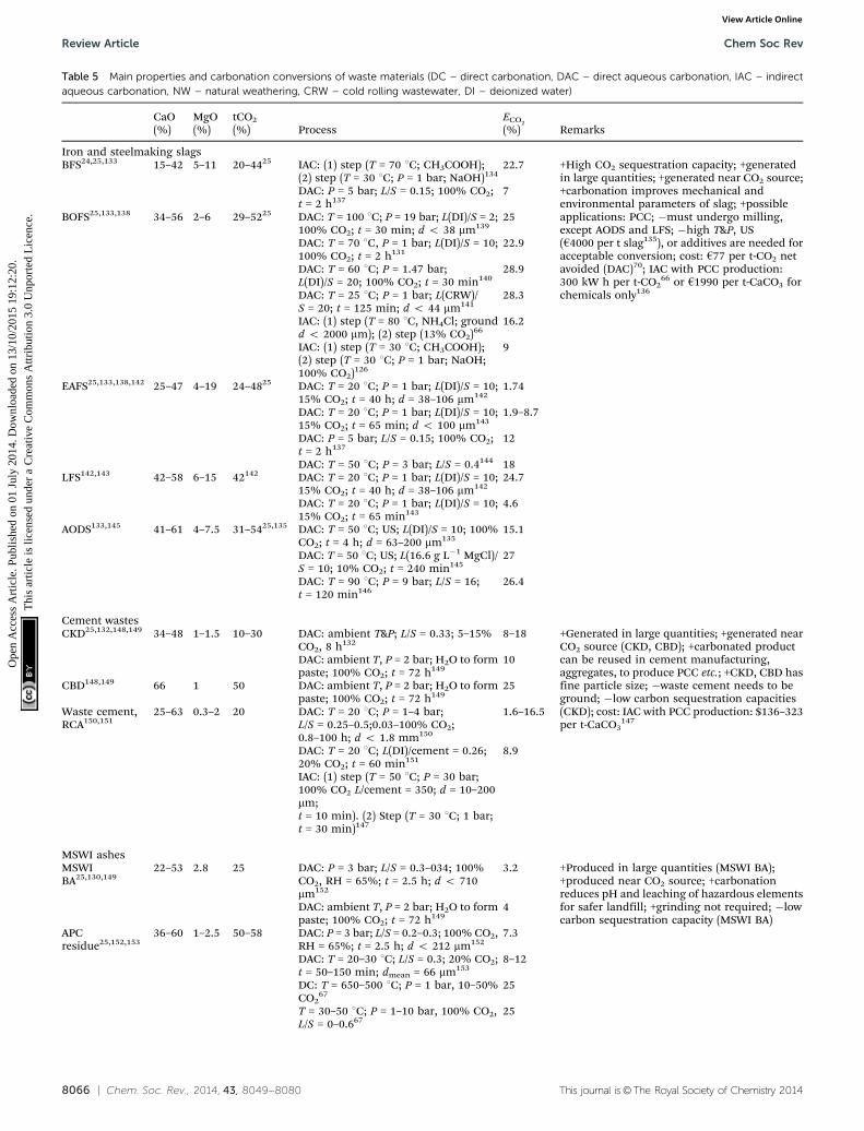
8066 | Chem. Soc. Rev., 2014, 43, 8049--8080 This journal is©The Royal Society of Chemistry 2014
Table 5 Main properties and carbonation conversions of waste materials (DC – direct carbonation, DAC – direct aqueous carbonation, IAC – indirectaqueous carbonation, NW – natural weathering, CRW – cold rolling wastewater, DI – deionized water)
CaO(%)
MgO(%)
tCO2
(%) ProcessECO2
(%) Remarks
Iron and steelmaking slagsBFS24,25,133 15–42 5–11 20–4425 IAC: (1) step (T = 70 1C; CH3COOH);
(2) step (T = 30 1C; P = 1 bar; NaOH)13422.7 +High CO2 sequestration capacity; +generated
in large quantities; +generated near CO2 source;+carbonation improves mechanical andenvironmental parameters of slag; +possibleapplications: PCC; �must undergo milling,except AODS and LFS; �high T&P, US(h4000 per t slag135), or additives are needed foracceptable conversion; cost: h77 per t-CO2 netavoided (DAC)70; IAC with PCC production:300 kW h per t-CO2
66 or h1990 per t-CaCO3 forchemicals only136
DAC: P = 5 bar; L/S = 0.15; 100% CO2;t = 2 h137
7
BOFS25,133,138 34–56 2–6 29–5225 DAC: T = 100 1C; P = 19 bar; L(DI)/S = 2;100% CO2; t = 30 min; d o 38 mm139
25
DAC: T = 70 1C, P = 1 bar; L(DI)/S = 10;100% CO2; t = 2 h131
22.9
DAC: T = 60 1C; P = 1.47 bar;L(DI)/S = 20; 100% CO2; t = 30 min140
28.9
DAC: T = 25 1C; P = 1 bar; L(CRW)/S = 20; t = 125 min; d o 44 mm141
28.3
IAC: (1) step (T = 80 1C, NH4Cl; groundd o 2000 mm); (2) step (13% CO2)66
16.2
IAC: (1) step (T = 30 1C; CH3COOH);(2) step (T = 30 1C; P = 1 bar; NaOH;100% CO2)126
9
EAFS25,133,138,142 25–47 4–19 24–4825 DAC: T = 20 1C; P = 1 bar; L(DI)/S = 10;15% CO2; t = 40 h; d = 38–106 mm142
1.74
DAC: T = 20 1C; P = 1 bar; L(DI)/S = 10;15% CO2; t = 65 min; d o 100 mm143
1.9–8.7
DAC: P = 5 bar; L/S = 0.15; 100% CO2;t = 2 h137
12
DAC: T = 50 1C; P = 3 bar; L/S = 0.4144 18LFS142,143 42–58 6–15 42142 DAC: T = 20 1C; P = 1 bar; L(DI)/S = 10;
15% CO2; t = 40 h; d = 38–106 mm14224.7
DAC: T = 20 1C; P = 1 bar; L(DI)/S = 10;15% CO2; t = 65 min143
4.6
AODS133,145 41–61 4–7.5 31–5425,135 DAC: T = 50 1C; US; L(DI)/S = 10; 100%CO2; t = 4 h; d = 63–200 mm135
15.1
DAC: T = 50 1C; US; L(16.6 g L�1 MgCl)/S = 10; 10% CO2; t = 240 min145
27
DAC: T = 90 1C; P = 9 bar; L/S = 16;t = 120 min146
26.4
Cement wastesCKD25,132,148,149 34–48 1–1.5 10–30 DAC: ambient T&P; L/S = 0.33; 5–15%
CO2, 8 h1328–18 +Generated in large quantities; +generated near
CO2 source (CKD, CBD); +carbonated productcan be reused in cement manufacturing,aggregates, to produce PCC etc.; +CKD, CBD hasfine particle size; �waste cement needs to beground; �low carbon sequestration capacities(CKD); cost: IAC with PCC production: $136–323per t-CaCO3
147
DAC: ambient T, P = 2 bar; H2O to formpaste; 100% CO2; t = 72 h149
10
CBD148,149 66 1 50 DAC: ambient T, P = 2 bar; H2O to formpaste; 100% CO2; t = 72 h149
25
Waste cement,RCA150,151
25–63 0.3–2 20 DAC: T = 20 1C; P = 1–4 bar;L/S = 0.25–0.5;0.03–100% CO2;0.8–100 h; d o 1.8 mm150
1.6–16.5
DAC: T = 20 1C; L(DI)/cement = 0.26;20% CO2; t = 60 min151
8.9
IAC: (1) step (T = 50 1C; P = 30 bar;100% CO2 L/cement = 350; d = 10–200mm;t = 10 min). (2) Step (T = 30 1C; 1 bar;t = 30 min)147
MSWI ashesMSWIBA25,130,149
22–53 2.8 25 DAC: P = 3 bar; L/S = 0.3–034; 100%CO2, RH = 65%; t = 2.5 h; d o 710mm152
3.2 +Produced in large quantities (MSWI BA);+produced near CO2 source; +carbonationreduces pH and leaching of hazardous elementsfor safer landfill; +grinding not required; �lowcarbon sequestration capacity (MSWI BA)
DAC: ambient T, P = 2 bar; H2O to formpaste; 100% CO2; t = 72 h149
4
APCresidue25,152,153
36–60 1–2.5 50–58 DAC: P = 3 bar; L/S = 0.2–0.3; 100% CO2,RH = 65%; t = 2.5 h; d o 212 mm152
7.3
DAC: T = 20–30 1C; L/S = 0.3; 20% CO2;t = 50–150 min; dmean = 66 mm153
8–12
DC: T = 650–500 1C; P = 1 bar, 10–50%CO2
6725
T = 30–50 1C; P = 1–10 bar, 100% CO2,L/S = 0–0.667
25
Review Article Chem Soc Rev
Ope
n A
cces
s A
rtic
le. P
ublis
hed
on 0
1 Ju
ly 2
014.
Dow
nloa
ded
on 1
3/10
/201
5 19
:12:
20.
Thi
s ar
ticle
is li
cens
ed u
nder
a C
reat
ive
Com
mon
s A
ttrib
utio
n 3.
0 U
npor
ted
Lic
ence
.View Article Online
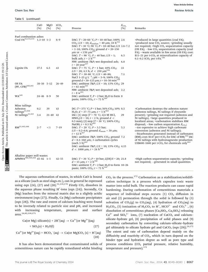
This journal is©The Royal Society of Chemistry 2014 Chem. Soc. Rev., 2014, 43, 8049--8080 | 8067
The aqueous carbonation of wastes, in which CaO is boundas a silicate (such as steel slags etc.), can in general be expressedusing eqn (24), (27) and (28).21,139,170 Firstly CO2 dissolves inthe aqueous phase resulting H+-ions (eqn (24)). Secondly, Ca(Mg) leaches from the mineral matrix due to a slightly acidicenvironment (eqn (27)). Finally, Ca (Mg) carbonate precipitates(eqn (28)). The rate and extent of calcium leaching were foundto be inversely related to particle size and pH, and increasedwith increasing temperature, pressure and surfacearea.24,82,130,171
Ca(or Mg) silicate(s) + 2H+(aq) - Ca2+(or Mg2+)(aq)
+ SiO2(s) + H2O(l) (27)
Ca2+(or Mg2+)(aq) + HCO3�(aq) - Ca(or Mg)CO3 (s) + H+(aq)
(28)
It has also been demonstrated that contaminated solids ofcementitious nature can be rapidly remediated whilst binding
CO2 in the process.172 Carbonation as a stabilization/solidifi-cation technique is a process which capsules toxic wastematter into solid bulk. The reaction products can cause rapidhardening. During carbonation of cementitious materials asequence of individual steps occurs: (1) CO2 diffusion inair and (2) permeation through the solid is followed by (3)solvation of CO2(g) to CO2(aq), (4) hydration of CO2(aq) toH2CO3, (5) ionization of H2CO3 to H+, HCO3� and CO3
2�, (6)dissolution of cementitious phases (Ca3SiO5, Ca2SiO4) releasingCa2+ and SiO4
2� ions, (7) nucleation of CaCO3 and calcium–silicate–hydrate gel, (8) precipitation of solid phases and (9)secondary carbonation by converting calcium–silicate–hydrategel ultimately to silicate hydrate gel and CaCO3 (eqn (29)).24,172
The extent and rate of carbonation depend mainly on thediffusivity and reactivity of CO2, which in turn depend on thebinder type and hydration degree as well as pore type andprocess conditions (CO2 partial pressure, relative humidity,temperature and pressure).172
Table 5 (continued )
CaO(%)
MgO(%)
tCO2
(%) ProcessECO2
(%) Remarks
Fuel combustion ashesCoal FA25,154,155 1.3–10 1–3 6–9 DAC: T = 20–60 1C; P = 10–40 bar; 100%
CO2; L/S = 10; dmedian = 40 mm; 18 h1542.6 +Produced in large quantities (coal FA);
+produced near CO2 source; +grinding usuallynot required; +high CO2 sequestration capacity(OS FA); �low CO2 sequestration capacity (coalFA); �waste available in few areas (OS FA); cost:$11–21 per t-CO2 at mineralization capacity of0.1–0.2 tCO2 per t-FA.156
DAC: T = 30 1C; 90 1C; P = 10–40 bar; L/S= 1–10; 100% CO2; ground d = 20–150mm or o150 mm155
3.6–7.2
DAC: T = 90 1C; P = 40 bar; L/S = 1;bulk ash; t = 2 h157
6.5
NW: ambient T&P; wet deposited ash;t = 20 year157
6.8
Lignite FA 27.5 6.5 43 DAC: T = 75 1C, P = 1 bar; 10% CO2;L/S = 20; 4.5 h; d o 250 mm158
23
DAC: T = 30–80 1C; L/S = 40–80;NaCl 1–25 g L�1; pH = 5–9; 100% CO2;ground d = 30–125 mm; t = 10–50 min159
7.1
OS FA(PF, CFB)160,161
38–50 5–12 26–49 DAC: ambient T&P; L/S = 10; 15% CO2;t = 65 min143
29
NW: ambient T&P; wet deposited ash;t = 8 w161
2.2
WA149 24–46 8–9 50 DAC: ambient T, P = 2 bar; H2O to formpaste; 100% CO2; t = 72 h149
8
Mine tailingsAsbestostailings23,164
0.2 39 43 DC: T = 375 1C; P = 1 bar; 56% CO2; 10%H2O; d = 37–75 mm; t = 5 h164
0.5 +Carbonation destroys the asbestos nature(asbestos tailings, Ni tailings if chrysotilepresent); +grinding not required (asbestos andNi tailings), +large quantities produced inlocalized areas; +carbonation stabilizes RMdisposal; �low carbon sequestration ECO2
;�too expensive to achieve high carbonateconversion (asbestos and Ni tailings);�bicarbonates generated instead of carbonates(RM); cost: $147 per t-CO2 for DAC of RM;162 IACof Ni tailings with hydromagnesite productionUS$600–1600 per t-CO2 for chemicals only163
Ni tailings23,165 3.4 21–40 43 IAC: (1) step (T = 70 1C; L(4 M HCl,HNO3)/S = 10; t = 2 h; ground d o0.5 mm); (2) step (T = 30 1C; 100% CO2;NaOH; t = 0.5 h)165
29
RM23,162,166 2–7 o1 7–19 DAC: T = 20 1C; P = 3.5 bar;L/S = 0.2–0.6; ground dmean = 30 mm;t = 12 h167
5.3
DAC: ambient T&P; 100% CO2; groundd = 0.1–160 mm; 3 carbonation cycles(each 5 h)162
7.2
DAC: ambient T&P; L/S = 10; 15% CO2;d o 1000 mm; t = 24 h166
4.15
Alkaline paper mill wastesAPMWA148,149,168 45–82 1–5 42–55 DAC: T = 30 1C; P = 10 bar; L(DI)/S = 20;
d = 15 mm; t = 2 h16821.8 +High carbon sequestration capacity; +grinding
not required; �generated in small quantitiesDAC: ambient T, P = 2 bar; H2O to formpaste; 100% CO2; t = 72 h149
10–26
Chem Soc Rev Review Article
Ope
n A
cces
s A
rtic
le. P
ublis
hed
on 0
1 Ju
ly 2
014.
Dow
nloa
ded
on 1
3/10
/201
5 19
:12:
20.
Thi
s ar
ticle
is li
cens
ed u
nder
a C
reat
ive
Com
mon
s A
ttrib
utio
n 3.
0 U
npor
ted
Lic
ence
.View Article Online
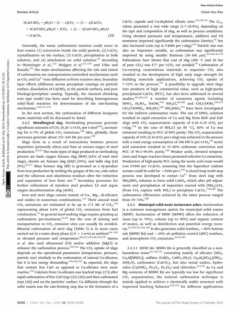
8068 | Chem. Soc. Rev., 2014, 43, 8049--8080 This journal is©The Royal Society of Chemistry 2014
3CaO�SiO2 + yH2O + (3 � x)CO2 - (3 � x)CaCO3
+ xCaO�SiO2�yH2O + zCO2 - (x � z)CaO�SiO2�yH2O
+ zCaCO3 (29)
Generally, the waste carbonation reaction could occur infour routes: (1) conversion inside the solid particle, (2) CaCO3
crystallization on the surface, (3) CaCO3 precipitation in bulksolution, and (4) attachment on solid solution.24 Accordingto Huntzinger et al.,132 Huijgen et al.127,139 and Uibu andKuusik,173 the main mechanisms affecting the rate and extentof carbonation are transportation-controlled mechanisms suchas CO2 and Ca2+-ions diffusion to/from reaction sites, boundarylayer effects (diffusion across precipitate coatings on particlesurface, dissolution of Ca(OH)2 at the particle surface), and poreblockage/precipitate coating. Typically, the classical shrinkingcore type model has been used for describing heterogeneoussolid–fluid reactions for determination of the rate-limitingmechanism.132,174–176
In the next section, the carbonation of different inorganicwaste materials will be discussed in detail.
3.2.2 Metallurgical slag. Steelmaking processes generatesignificant amounts of CO2 (0.28–1 t-CO2 per t-steel142), account-ing for 6–7% of global CO2 emissions.138 Also, globally, theseprocesses generate about 315–420 Mt per year.126
Slags form as a result of interactions between processimpurities (primarily silica) and lime at various stages of steelproduction.23,133 The main types of slags produced at steelmakingprocess are basic oxygen furnace slag (BOF) (62% of total steelslags), electric arc furnace slag (EAF) (29%), and ladle slag (LS)(9%).25,177 Blast furnace slag (BF) is generated as a by-productfrom iron production by melting the gangue of the ore, coke ashesand the siliceous and aluminous residues after the reductionand separation of iron from ore.25 Secondary processes forfurther refinement of stainless steel produce LS and argonoxygen decarburization slag (AOD).
Iron and steel slags consist mainly of Ca-, Mg-, Al-silicatesand oxides in numerous combinations.133 Their annual totalCO2 emissions are estimated to be up to 171 Mt of CO2,134
representing about 0.6% of global CO2 emissions from fuelcombustion.23 In general steel-making slags require grinding ascarbonation pre-treatment,23,48 but the cost of mining andtransportation to CO2 emission sites can usually be avoided.Mineral carbonation of steel slag (Table 5) is in most casescarried out in a water slurry phase (L/S 4 1 w/w) at ambient141–143
or elevated pressure and temperature.66,127,139,140,176,178 Santoset al. also used ultrasound (US) and/or additives (MgCl) toenhance the carbonation process.135,145 The CO2 uptake of slagsdepends on the operational parameters (temperature, pressure,particle size) similarly to the carbonation of natural Ca-silicates;but it is less energy demanding.139,142,176 As expected, the slagsthat contain free CaO as opposed to Ca-silicates were morereactive.142 Calcium from Ca-silicates was leached (eqn (27)) afterrapid carbonation of free CaO (eqn (22)–(26)) and then carbonated(eqn (28)) and on the particles’ surface. Ca diffusion through thesolid matrix was the rate-limiting step due to the formation of a
CaCO3 capsule and Ca-depleted silicate zone.23,139,176 The ECO2
values presented a very wide range (1.7–28.9%), depending onthe type and composition of slag, as well as process conditions.Using elevated pressures and temperatures, additives and UStreatment improved significantly the carbonation kinetics,25 butalso increased costs (up to h4000 per t-slag).135 Particle size wasalso an important variable, as carbonation was significantlyimproved by using smaller fractions (38–106 mm).25,139,142,176
Estimations have shown that cost of slag (200 1C and 20 barof pure CO2) was h77 per t-CO2 net avoided.70 Carbonation ofCa-carrying cementitious materials to sequester CO2 alsoresulted in the development of high early stage strength forbuilding materials applications, achieving CO2 uptake of7–12% in the process.137 A possibility to upgrade steel slagsinto products of high commercial value, such as high-purityprecipitated CaCO3 (PCC), has also been addressed in severalstudies.66,126,133 A number of extraction agents includingHNO3, H2SO4, NaOH,138 NH4Cl,66,106 and CH3COOH,126,133
CH3COONH4, NH4NO3106 NH4HSO4
179 have been investigatedfor the indirect carbonation route. The use of HNO3 solutionresulted in rapid extraction of Ca and Mg from BOF and EAFslags with CO2 sequestration capacity of 0.26–0.38 tCO2 pert-slag.138 In the case of NH4Cl (at 80 1C), 60% of Ca wasextracted resulting in PCC of 98% purity. The CO2 sequestrationcapacity of 16% (0.16 tCO2 per t-slag) was achieved in the processwith a total energy consumption of 300 kW h per t-CO2.66 Aceticacid extraction resulted in 31–86% carbonate conversion andPCC of 99.5–99.8% purity.126 Weaker acids, elevated tempera-tures and longer reaction times promoted selective Ca extraction.Production of high-purity PCC using the acetic acid route wouldcost h1990 per t-CaCO3 assuming that the byproduct sodiumacetate could be sold for Bh680 per t.136 A closed loop multi-stepprocess was developed to extract Ca2+ from steel slag withNH4HSO4 solution to form solid CaSO4, which after pH adjust-ment and precipitation of impurities reacted with (NH4)2CO3
(from CO2 capture with NH3) to precipitate CaCO3.179,180 Thecarbonation efficiencies achieved by the latter process rangedfrom 59–74%.180
3.2.3 Municipal solid waste incinerator ashes. Incinerationis a common management option for municipal solid wastes(MSW). Incineration of MSW (MSWI) offers the reduction ofmass (up to 70%), volume (up to 90%) and organic contentof wastes, as well as disinfection and potential energy recov-ery.23,130,152,181,182 It also generates solid residues, B80% bottomash (MSWI BA) and B20% air pollution control (APC) residues,and atmospheric CO2 emissions.23,25,183
3.2.3.1 MSWI BA. MSWI BA is generally classified as a non-hazardous waste23,130,152 consisting mainly of silicates (SiO2,Ca2Al[AlSiO7]), sulfates (CaSO4, CaSO4�2H2O, Ca6Al2(SO4)3(OH)12�26H2O), carbonates (CaCO3), but also metal oxides, hydro-xides (Ca(OH)2, Fe2O3, Fe3O4) and chlorides.25,130 As Ca andMg contents of MSWI BA are typically too low for significantCO2 sequestration, the mineral carbonation technique ismainly applied to achieve a chemically stable structure withimproved leaching behavior130,152 for different applications
Review Article Chem Soc Rev
Ope
n A
cces
s A
rtic
le. P
ublis
hed
on 0
1 Ju
ly 2
014.
Dow
nloa
ded
on 1
3/10
/201
5 19
:12:
20.
Thi
s ar
ticle
is li
cens
ed u
nder
a C
reat
ive
Com
mon
s A
ttrib
utio
n 3.
0 U
npor
ted
Lic
ence
.View Article Online

This journal is©The Royal Society of Chemistry 2014 Chem. Soc. Rev., 2014, 43, 8049--8080 | 8069
(e.g. secondary building material in road sub-bases, wind andnoise barriers, etc.).23,183
Mineral carbonation of MSWI BA has been examined andcompared to natural weathering to reduce alkalinity and tracemetal mobility.152,184–186 Rate-controlling mechanisms and theeffect of operating parameters, such as temperature, CO2 partialpressure, liquid to solid ratio (optimum L/S B 0.3 w/w152,182),residence time, and particle size152,183 have also been investi-gated. MSWI BA has shown CO2 uptake on the order of3.0–6.5 wt%130,149,152,183 (Table 5). Baciocchi et al.187 testedBA from refuse derived fuel (RDF) incineration with CO2 uptakeranging from 4–14% depending on particle size.
The mechanisms involved in the carbonation of thesematerials are complex. Although most of the studies have onlyconsidered Ca(OH)2 carbonation,71,183 it is likely that Ca- andMg-silicates also take part in CO2 binding reactions. Thedissolution of Ca from the solid matrix into the liquid phaseand the diffusion of CO2 into the pores have been reported asthe rate-limiting steps.130 The kinetics of CO2 uptake includethe two following reaction steps: (1) an initial rapid CO2 uptake,which involves ‘‘faster’’ reacting minerals such as Ca(OH)2 andfollowed by (2) a decrease in the rate until an approximatelyconstant value of CO2 uptake is achieved,152,183,184 whichinvolves less-reactive Ca–Mg-silicates.139
3.2.3.2 APC residues. APC residues are formed in the processof the flue gas treatment and typically contain a mixture offly ash, unburned carbon and unreacted lime. Due to thelime content (typically pH 4 12), and high concentration ofheavy metals (Zn, Pb, Cd, Cr, Cu, Hg, Ni), soluble salts andchlorinated compounds, APC residues are classified as a hazar-dous waste.23,25,152 High percentage of readily-active calciumhydroxides makes the carbonation of APC residues potentiallysuitable for CO2 sequestration.152,188 Also, the APC carbonationproducts present a pH value that meets the regulatory limits(pH o 9.5).172,189
The carbonation route for APC residues is more straight-forward as compared to MSWI BA, since the main reactivespecies include Ca(OH)2 and CaClOH. The kinetics of CO2
uptake showed a similar trend as for MSWI BA, only with higherweight gains attributed to higher lime contents and largerspecific surface areas.152 The ECO2
uptake of the APC residuesranges from 7 to 25 wt% (0.07–0.25 t-CO2 per t-APC)25,67,152,153,188
(Table 5). Baciocchi et al. compared dry (1 bar, 10–50% CO2,350–500 1C) and wet routes (1–10 bar, 100% CO2, 30–50 1C, L/S =0–0.6). Although both routes achieved a similar maximum con-version to carbonates (65%), corresponding to a potential CO2
storage capacity of 0.25 t per t-APC residue, the dry routepresented faster reaction kinetics.67
3.2.4 Power plant ashes. Coal fired power plants provideca. 40% of world’s electricity,154 generating annually 12 000 MtCO2 and 600 Mt fly ash (FA).23,25 About 30% of coal FA isutilized for construction materials.25 Coal FA is a fine powder(particle size typically 10–15 mm), whose composition variesdepending on the mineral content of fuel. Generally, it consistsof an amorphous aluminosilicate glass matrix (SixAlyOz) and
recrystallized minerals, including quartz (SiO2), cristobalite(SiO2) and mullite (3Al2O32SiO2).25 The main components ofbituminous coal FA are SiO2, Al2O3, Fe2O3, MgO (1–3%) andCaO (5–10%) and various amounts of unburned carbon.25
FA from oil-shale (OS, low-grade fossil fuel) combustion hasbeen investigated as a potential sorbent for mineral carbonation.OS FA contains 12–30% free CaO, depending on combustionregimes (PF or CFB).169 Also, potential CO2 sorbents are pro-duced in power plants that co-fire wood and coal. The resultingwood ash (WA) contains about 45% CaO.149
The maximum CO2 sequestration potential of bituminouscoal FA is relatively low B9 wt%,25,154 but it could be as high as43–49% for Ca-rich lignite type coal or oil shale ashes143,158
(Table 5). Studies have mainly been focused on the directaqueous carbonation route under mild process conditions witheither water154,157,158,169 or brine155,190 as the reaction mediumor by natural weathering over a longer period of time.157,161
A pilot scale mineral carbonation process was developed andtested by reacting coal FA with flue gases in a fluidized bedreactor at a 2120 MW coal-fired power plant in Point of Rocks,USA. A preliminary economic analysis of the process reportedthat 90% CO2 capture from a 532 MW power plant would costabout $11–21 per t-CO2 assuming a sequestration capacity of0.1–0.2 t-CO2 per t-FA.156 According to general estimates, coal FAwith an average CO2 sequestration capacity of 5% could sequester0.25% of CO2 emissions from coal fired power plants.23,25,154
3.2.5 Cement wastes. Cement kiln dust (CKD) is a fineby-product of Portland cement and lime high-temperaturerotary kiln production.25 The cement industry generates 0.15–0.20 t of CKD per tonne of cement (world output 2.8 Gt)23,25,132
and 5% of global CO2 emissions.191 CKD is characterized as apotentially hazardous waste due to its caustic nature23,191 anddisposed into appropriate landfills or stockpiles. Typical CKDcontains 38–48% CaO and 1.5–2.1% MgO23,25,132 (Table 5), buta significant amount of CKD is already carbonated (CKDcontains 46–57% CaCO3
132). Cement bypass dusts (CBD), whichare removed after kiln firing, have much lower carbonatecontent than CKD, and therefore much higher potential tocapture CO2 (0.5 t-CO2 per t-CBD).148 The CKD ECO2
uptakeachieved was 8–25 wt% (i.e. 0.08–0.25 t-CO2 per t-CKD,CBD) atambient temperature and pressure in a column reactor132 or ina pressurized reactor.148 According to Bobicki et al.,23 CKD canpotentially sequester up to 42 Mt of CO2 annually, or about0.1% of global CO2 emissions from fuel combustion. Also, as aresult of carbonation, potential health hazard associated withCKD disposal is eliminated.128
Waste cement is a by-product obtained from the aggregaterecycling process, where waste concrete is pulverized andclassified to separate the aggregate from the waste cement.According to Bobicki et al.,23 waste cement has a potential tostore up to 61 Mt CO2 considering the annual waste concreteproduction of 1100 Mt from EU, USA and China together.23
However, the majority of waste cement is currently alreadyreused in construction applications.25
Teramura et al.150 used a CO2-activated hardening process toproduce building materials, where waste cement was mixed
Chem Soc Rev Review Article
Ope
n A
cces
s A
rtic
le. P
ublis
hed
on 0
1 Ju
ly 2
014.
Dow
nloa
ded
on 1
3/10
/201
5 19
:12:
20.
Thi
s ar
ticle
is li
cens
ed u
nder
a C
reat
ive
Com
mon
s A
ttrib
utio
n 3.
0 U
npor
ted
Lic
ence
.View Article Online
8070 | Chem. Soc. Rev., 2014, 43, 8049--8080 This journal is©The Royal Society of Chemistry 2014
with water (50% H2O) before moulding it into bricks, curingwith CO2 and drying overnight (with maximum ECO2
16.5%, at100% CO2 and 4 bar, Table 5). Kashef-Haghighi and Ghoshal151
achieved a carbonation efficiency of 18% and an ECO2of 8.9%
by curing fresh concrete blocks in a flow-through reactor(20% CO2 in N2, 20 1C and 60 min). A small demonstrationscale is planned for the technology of using point source CO2
emission to limit the need for heat and steam in the curingprocess in the production of precast concrete products.192
Katsuyama et al.147 and Iizuka et al.171 produced high purityCaCO3 using an indirect aqueous carbonation route for theextraction of Ca2+ from cement waste by pressurized CO2
(30 bar) and subsequent carbonation at reduced pressures(1 bar). The estimated costs per 1 metric tonne of CaCO3 wereUS$136 for desulfurization and US$323 for high-purity CaCO3
(market price of CaCO3 of about $400 per tCaCO3147).
3.2.6 Mining tailings. Asbestos, copper, nickel, platinumdeposits, diamondiferous kimberlite pipes and podiform chromitedeposits hosted by dunite, serpentinite, and gabbronorite producetailings suitable for mineral carbonation.23,193 Also, the bauxiteresidue (red mud) from alumina processing is a suitable feedstockfor CO2 sequestration.162,166,167 In addition to CO2 storage, thecarbonation treatment also improves the properties of wastes,especially in the case of asbestos tailings and red mud, enablingsafer landfilling or reuse.23
3.2.6.1 Asbestos tailings. Production of 1 t of asbestos(4 Mt globally) generates ca. 20 t of tailings.23 The tailings fromchrysotile processing are often associated with residual asbestosand, are therefore classified as hazardous wastes. Carbonation ofasbestos tailings could be useful in several ways, as they containup to 40% MgO, the mining and size reduction are already doneand the asbestiform nature of the mineral is destroyed. Thus,both the remediation of a hazardous waste and the sequestrationof CO2 could be achieved.82 The natural weathering of old tailingpiles has been studied by several groups193,194 (Table 5). Wilsonet al.193 estimated that the chrysotile in the tailing piles hadcarbonated approximately 0.3% per year. It was suggested thatthe CO2 sequestration efficiency could be enhanced by optimiz-ing the surface area and particle size of the tailings, as well asbioleaching (adding microorganisms to increase solubilisationof alkaline earth metals).195 Larachi et al.164 investigated thedirect carbonation in dry and humid (humidity 0–10%) envir-onments over a range of temperatures (300–1200 1C) and lowCO2 pressures and achieved a maximum carbonate conversionof 0.5% after 5 h at 375 1C in a moist atmosphere. Carbonationof Mg-rich wastes such as asbestos tailings requires elevatedpressures and temperatures or pre-treatment, similar to serpentinetreatment, in order to achieve higher carbonate conversions.
3.2.6.2 Nickel tailings. As high-grade sulphide deposits arealmost depleted and laterites require more complex processingthan sulphide ores, the nickel industry has focused on low-grade sulphide resources, often hosted in ultramafic rocks.23
Processing ultramafic ores generates vast quantities of Mg-richtailings (40% MgO, Table 5). Valorizing these ultramafic tailings
could make marginal nickel projects economically feasible.196
Teir et al.163,165 extracted magnesium from serpentinite(from stockpile nickel tailings mine) using a variety of acids(HCl, HNO3) (Table 5). The Mg-extracts were carbonated(carbonate conversion 94%) in a multistage process with acarbonate conversion of 94% and producing individual preci-pitates of silica, iron oxide and hydromagnesite of 93–99%purity.165 However, the estimated costs for chemicals were onlyUS$600–1600 per tCO2.163 Integrating nickel mining operationswith CO2 sequestration requires further developments toreduce costs and a carbon regulatory framework including acap-and-trade scheme with sufficiently high carbon price.23
3.2.6.3 Red mud. Red mud (RM) is the caustic waste materialof bauxite ore processing for alumina extraction. Producing1 t of alumina generates 1.0–1.5 t of highly alkaline RM(70 Mt annually197).167 RM typically contains Fe2O3 (30–60%),Al2O3 (10–20%), SiO2 (3–50%), Na2O (2–10%), CaO (2–8%) andTiO2 (trace – 10%),162 which are present in portlandite(Ca(OH)2), sodium carbonate (Na2CO3), NaAl(OH)4, Na6[AlSiO4]6,crystalline hematite (Fe2O3), goethite (R-FeOOH), gibbsite(Al(OH)3), boehmite (g-AlOOH), sodalite (Na4Al3Si3O12Cl), ana-stase (TiO2), rutile (TiO2), katoite (Ca3Al2SiO4(OH)12), gypsum(CaSO4�2H2O), and quartz (SiO2).166 Mineral carbonation of RMreduces its toxicity and leaching behavior in terms of long-termstorage in addition to CO2 sequestration.167,197 Carbonated RMcan also be used for various applications such as fertilizers, brickand tile industry, plastics industry, wastewater treatment andcement production.166 RM is generally carbonated via a directprocess route at ambient temperatures and pressures162,166,167
and a sequestration capacity of 0.04–0.05 tCO2 per t RM has beenreported (Table 5). The roughly calculated cost of CO2 sequestra-tion is at US$147 per t-CO2.162 At Kwinana in Western Australia,Alcoa operates a residue carbonation plant, where gaseous CO2
from a nearby ammonia plant is contacted with RM, reducingthe pH of the slurry to a less hazardous level and capturing in theprocess 0.030-0.035 tCO2 per t of RM.192
As the primary source of alkalinity in RM is NaOH, the maincarbonation products are Na2CO3 and NaHCO3.162 SolubleNa-carbonates provide a less permanent CO2 storage than solidCa–Mg-carbonates because of their solubility. In order toprovide a more permanent CO2 storage option, RM was mixedwith brine solution (solution of hydrated Ca- and Mg-chlorides)prior to carbonation.197,198 It has been estimated that over100 Mt of CO2 have been sequestered in RM through the naturalweathering of historically produced RM (6 Mt annually).199 Byutilizing appropriate technologies for incorporating bindingcations into RM, approximately 6 Mt of additional CO2 couldbe sequestered whilst RM is also remediated.199
3.2.7 Alkaline paper mill wastes. Cellulose pulp productionfor paper manufacture results in the formation of several typesof alkaline paper mill wastes (APMW), which typically contain45–82%148,168 free CaO and are therefore suitable sorbents formineral carbonation (Table 5). The pulp mills also generateCO2, which could be used to carbonate the APMW. ProducedCaCO3 could be utilized in the pulp and paper industry or sold
Review Article Chem Soc Rev
Ope
n A
cces
s A
rtic
le. P
ublis
hed
on 0
1 Ju
ly 2
014.
Dow
nloa
ded
on 1
3/10
/201
5 19
:12:
20.
Thi
s ar
ticle
is li
cens
ed u
nder
a C
reat
ive
Com
mon
s A
ttrib
utio
n 3.
0 U
npor
ted
Lic
ence
.View Article Online

This journal is©The Royal Society of Chemistry 2014 Chem. Soc. Rev., 2014, 43, 8049--8080 | 8071
as a value-added by-product.23,168 DAC of APMW presents anECO2
of 16–27% (i.e. 0.16–0.27 tCO2 per t-APMW) at 20–30 1Cand 2–10 bar over 2–72 h.149,168
4. Product utilisation
The effective development of utilization routes for the materialsproduced by mineral carbonation could help to make thistechnology economically viable and facilitate its deployment.Based on the information discussed in the previous sections,processes that produce multiple separated products are pre-ferred in terms of products utilisation, due to high purityrequired by the market. Therefore, processes where cationsare extracted from the feed material in a separate step (indirectprocesses) may be suitable for controlling the morphology andparticle size of precipitated products for high-value applica-tions, compared to direct mineralisation technologies.200,201
It has been shown that indirect processes are generally ableto separate silica, magnesium/calcium carbonate and ironhydroxides with purities as high as 90% by switching the pHof the solution from acidic to basic.10,72,200,202 The dissolutionof silicates selectively removes Mg/Ca and other elements fromthe mineral matrix, leaving behind silica in amorphous phasewith particle in the range of tens of microns and purity of about80%.163,200 Precipitated hydromagnesite (Mg5(CO3)4(OH)2
4H2O) with purity 493 wt% can be produced by indirectprocesses.72,163,201 Also, 99 wt% pure calcite with particles45 mm have been produced by carbonation of wollastoniteunder mild conditions (10 bar, 100 1C).200 However, purityrequired to access high-value markets is difficult to be achievedwithout extra purification steps.10
Applications of carbonate products can be divided into low-end high-volume and high-end low-volume uses. For the MCproducts to be commercially used there are specifications andquality criteria that must be met (e.g. particle size, distributionand low level of contaminants). Construction and filler applica-tions seem to be the most appropriate for silica and carbonateproducts, respectively, while feedstock for iron/steel works mayrepresent the natural pathway for iron oxides from MC. Amongthe low end applications, MC products as liming agents tobuffer the acidity of soils are promising, but require the MCproducts to be free from potential pollutants that might derivefrom particular flue gas or mineral wastes converted intocarbonates. Also, land reclamation from the sea in coastal areasand mine reclamation using silica, magnesium and calciumcarbonates are other possible low-tech high-volume applications.10
High-end applications usually require stringent specifica-tions. Mono-disperse nano-particles uniform in size, shape andcomposition have a wide number of applications in industry,such as catalysts, chromatography, ceramics, pigments, pharmacy,photographic emulsions, etc.203
MC can be used to produce silica in the amorphous phaseand with particles smaller than o30 mm, which could serve as apozzolanic cement replacement material or as a filler.204 Silicafrom MC, for deoxydiser in steel making, circuit boards, ceramix
matrix composites, semiconductors should reach very highpurity (SiO2 4 98.5%; Fe2O3 o 0.1%, Al2O3 o 0.15%).10,205
Similar purity is expected for ceramics applications, whileslightly lower purity would be required for use a refractorymaterial (95% SiO2) and iron and steel making (90% SiO2).It is unlikely that MC products can reach purity levels requiredfor silicon applications without additional post-processing.Amorphous silica, which is a fine powder and it is currentlyconsidered a high quality reactive cement additive, may repre-sent the most likely application for amorphous silica from MC.10
Calcium carbonate is extensively used as a novel functionalmaterial in several fields such as plastics, rubber, paint, print-ing ink, weaving, toothpaste, make-up, and foodstuffs. Calciumcarbonate is a product in MC processes that use inorganicwastes or calcium silicates, such as wollastonite.
An interesting perspective to filler technology is the devel-opment of nano-sized, high performance, and low cost fillersfrom calcium carbonates in the form of ground calcium carbo-nate (GCC) and precipitated calcium carbonate (PCC).10 Calciumcarbonate can precipitate in six different forms, namely amor-phous calcium carbonate (ACC), hexahydrate calcium carbonate(HCC), monohydrate calcium carbonate (MCC) and the poly-morphs calcite, aragonite and vaterite, which have the trigonal,orthorhombic, and hexagonal crystal system, respectively.206 Forthe PCC applications, several physical and chemical properties,such as particle size average and distribution, morphology, specificsurface area, polymorph or the chemical purity are very importantin determining the potential market.207 The different polymorphsof CaCO3 can have different functions as additives. For example,dispersion can be increased if cubic CaCO3 is added as an additionin paint; acicular or rod-like CaCO3 has a reinforcing effect onrubber and plastics; and spherical CaCO3 has a significant impacton the brightness and transparency of ink.208
By controlling the initial concentration of the reagents,stirring speed, pH, type and amount of additives, and otherreaction conditions, CaCO3 with different polymorphs, morpho-logies, and grain sizes can be obtained. For example, differentCaCO3 polymorphs were generated by changing the carbonationtime or after aging.208
Particle sizes and morphologies of precipitated CaCO3
varied from rhombohedral (15–35 nm) to scalenohedral(400 nm in diameter and 2 mm in length) upon changing theoperating variables, CaO concentration, the CO2 flow rate andsurfactants concentration.203 Addition of the ethyltrimethylammonium bromide cationic surfactant (2%) produced narrowsize rounded particle morphologies either rhombohedral orspherical and a limited amount of agglomerate.203
Finally, enzymes such as Carbonic Anhydrase (CA) havebeen used to enhance carbonation efficiency and modifythe properties of the reaction products. Mesoporous aluminasynthesized from the egg shell membrane and pore-expandedSBA-15 was used as a template to immobilise CA.209,210 Thecarbonation capacity of alumina immobilized CA was found tobe 25% lower compared to that obtained in the presence offree CA.209 Favre et al. reported that at higher pH, calcite andvaterite were observed while at lower pH, only calcite was
Chem Soc Rev Review Article
Ope
n A
cces
s A
rtic
le. P
ublis
hed
on 0
1 Ju
ly 2
014.
Dow
nloa
ded
on 1
3/10
/201
5 19
:12:
20.
Thi
s ar
ticle
is li
cens
ed u
nder
a C
reat
ive
Com
mon
s A
ttrib
utio
n 3.
0 U
npor
ted
Lic
ence
.View Article Online
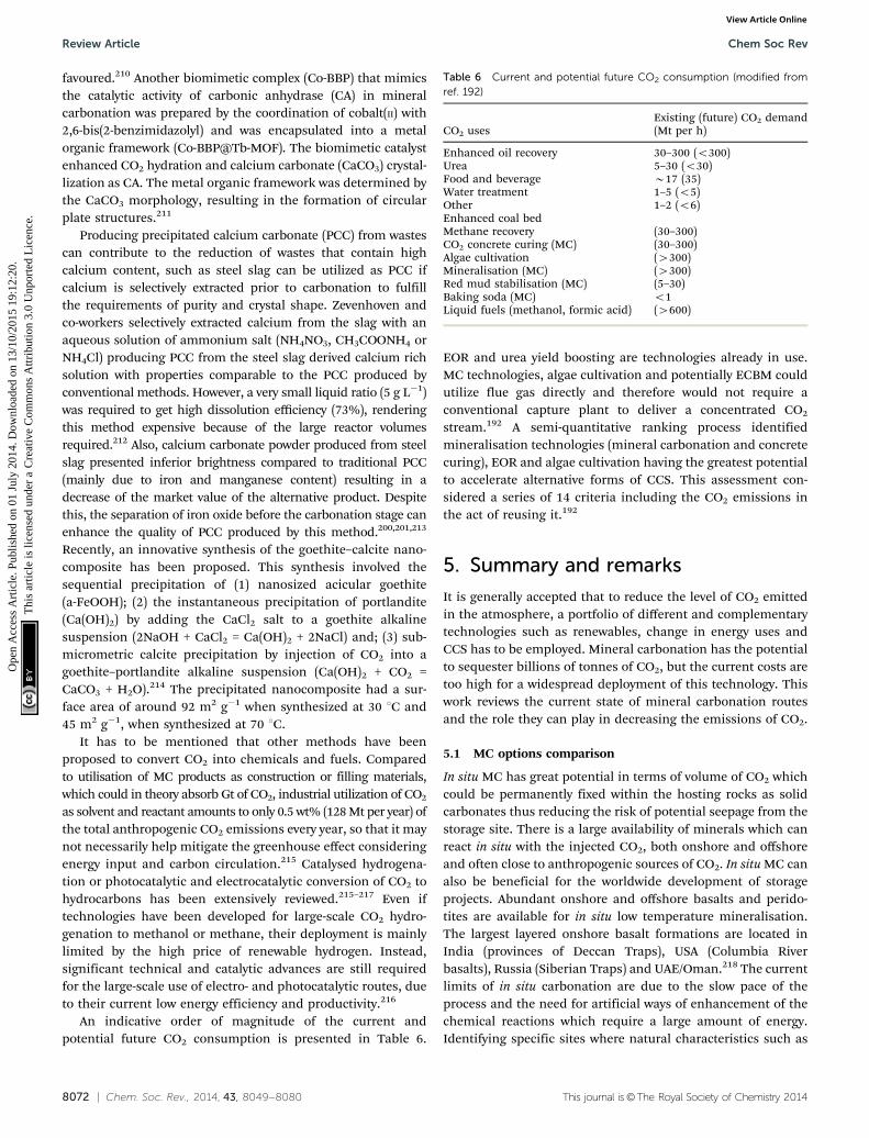
8072 | Chem. Soc. Rev., 2014, 43, 8049--8080 This journal is©The Royal Society of Chemistry 2014
favoured.210 Another biomimetic complex (Co-BBP) that mimicsthe catalytic activity of carbonic anhydrase (CA) in mineralcarbonation was prepared by the coordination of cobalt(II) with2,6-bis(2-benzimidazolyl) and was encapsulated into a metalorganic framework (Co-BBP@Tb-MOF). The biomimetic catalystenhanced CO2 hydration and calcium carbonate (CaCO3) crystal-lization as CA. The metal organic framework was determined bythe CaCO3 morphology, resulting in the formation of circularplate structures.211
Producing precipitated calcium carbonate (PCC) from wastescan contribute to the reduction of wastes that contain highcalcium content, such as steel slag can be utilized as PCC ifcalcium is selectively extracted prior to carbonation to fulfillthe requirements of purity and crystal shape. Zevenhoven andco-workers selectively extracted calcium from the slag with anaqueous solution of ammonium salt (NH4NO3, CH3COONH4 orNH4Cl) producing PCC from the steel slag derived calcium richsolution with properties comparable to the PCC produced byconventional methods. However, a very small liquid ratio (5 g L�1)was required to get high dissolution efficiency (73%), renderingthis method expensive because of the large reactor volumesrequired.212 Also, calcium carbonate powder produced from steelslag presented inferior brightness compared to traditional PCC(mainly due to iron and manganese content) resulting in adecrease of the market value of the alternative product. Despitethis, the separation of iron oxide before the carbonation stage canenhance the quality of PCC produced by this method.200,201,213
Recently, an innovative synthesis of the goethite–calcite nano-composite has been proposed. This synthesis involved thesequential precipitation of (1) nanosized acicular goethite(a-FeOOH); (2) the instantaneous precipitation of portlandite(Ca(OH)2) by adding the CaCl2 salt to a goethite alkalinesuspension (2NaOH + CaCl2 = Ca(OH)2 + 2NaCl) and; (3) sub-micrometric calcite precipitation by injection of CO2 into agoethite–portlandite alkaline suspension (Ca(OH)2 + CO2 =CaCO3 + H2O).214 The precipitated nanocomposite had a sur-face area of around 92 m2 g�1 when synthesized at 30 1C and45 m2 g�1, when synthesized at 70 1C.
It has to be mentioned that other methods have beenproposed to convert CO2 into chemicals and fuels. Comparedto utilisation of MC products as construction or filling materials,which could in theory absorb Gt of CO2, industrial utilization of CO2
as solvent and reactant amounts to only 0.5 wt% (128 Mt per year) ofthe total anthropogenic CO2 emissions every year, so that it maynot necessarily help mitigate the greenhouse effect consideringenergy input and carbon circulation.215 Catalysed hydrogena-tion or photocatalytic and electrocatalytic conversion of CO2 tohydrocarbons has been extensively reviewed.215–217 Even iftechnologies have been developed for large-scale CO2 hydro-genation to methanol or methane, their deployment is mainlylimited by the high price of renewable hydrogen. Instead,significant technical and catalytic advances are still requiredfor the large-scale use of electro- and photocatalytic routes, dueto their current low energy efficiency and productivity.216
An indicative order of magnitude of the current andpotential future CO2 consumption is presented in Table 6.
EOR and urea yield boosting are technologies already in use.MC technologies, algae cultivation and potentially ECBM couldutilize flue gas directly and therefore would not require aconventional capture plant to deliver a concentrated CO2
stream.192 A semi-quantitative ranking process identifiedmineralisation technologies (mineral carbonation and concretecuring), EOR and algae cultivation having the greatest potentialto accelerate alternative forms of CCS. This assessment con-sidered a series of 14 criteria including the CO2 emissions inthe act of reusing it.192
5. Summary and remarks
It is generally accepted that to reduce the level of CO2 emittedin the atmosphere, a portfolio of different and complementarytechnologies such as renewables, change in energy uses andCCS has to be employed. Mineral carbonation has the potentialto sequester billions of tonnes of CO2, but the current costs aretoo high for a widespread deployment of this technology. Thiswork reviews the current state of mineral carbonation routesand the role they can play in decreasing the emissions of CO2.
5.1 MC options comparison
In situ MC has great potential in terms of volume of CO2 whichcould be permanently fixed within the hosting rocks as solidcarbonates thus reducing the risk of potential seepage from thestorage site. There is a large availability of minerals which canreact in situ with the injected CO2, both onshore and offshoreand often close to anthropogenic sources of CO2. In situ MC canalso be beneficial for the worldwide development of storageprojects. Abundant onshore and offshore basalts and perido-tites are available for in situ low temperature mineralisation.The largest layered onshore basalt formations are located inIndia (provinces of Deccan Traps), USA (Columbia Riverbasalts), Russia (Siberian Traps) and UAE/Oman.218 The currentlimits of in situ carbonation are due to the slow pace of theprocess and the need for artificial ways of enhancement of thechemical reactions which require a large amount of energy.Identifying specific sites where natural characteristics such as
Table 6 Current and potential future CO2 consumption (modified fromref. 192)
CO2 usesExisting (future) CO2 demand(Mt per h)
Enhanced oil recovery 30–300 (o300)Urea 5–30 (o30)Food and beverage B17 (35)Water treatment 1–5 (o5)Other 1–2 (o6)Enhanced coal bedMethane recovery (30–300)CO2 concrete curing (MC) (30–300)Algae cultivation (4300)Mineralisation (MC) (4300)Red mud stabilisation (MC) (5–30)Baking soda (MC) o1Liquid fuels (methanol, formic acid) (4600)
Review Article Chem Soc Rev
Ope
n A
cces
s A
rtic
le. P
ublis
hed
on 0
1 Ju
ly 2
014.
Dow
nloa
ded
on 1
3/10
/201
5 19
:12:
20.
Thi
s ar
ticle
is li
cens
ed u
nder
a C
reat
ive
Com
mon
s A
ttrib
utio
n 3.
0 U
npor
ted
Lic
ence
.View Article Online
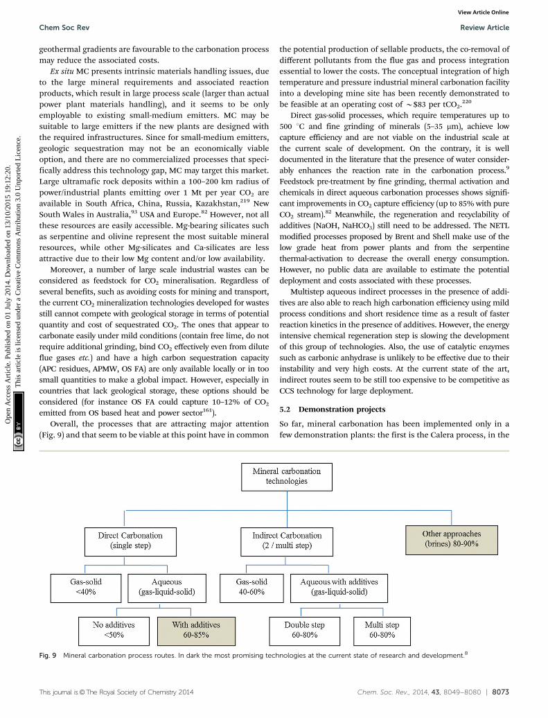
This journal is©The Royal Society of Chemistry 2014 Chem. Soc. Rev., 2014, 43, 8049--8080 | 8073
geothermal gradients are favourable to the carbonation processmay reduce the associated costs.
Ex situ MC presents intrinsic materials handling issues, dueto the large mineral requirements and associated reactionproducts, which result in large process scale (larger than actualpower plant materials handling), and it seems to be onlyemployable to existing small-medium emitters. MC may besuitable to large emitters if the new plants are designed withthe required infrastructures. Since for small-medium emitters,geologic sequestration may not be an economically viableoption, and there are no commercialized processes that speci-fically address this technology gap, MC may target this market.Large ultramafic rock deposits within a 100–200 km radius ofpower/industrial plants emitting over 1 Mt per year CO2 areavailable in South Africa, China, Russia, Kazakhstan,219 NewSouth Wales in Australia,93 USA and Europe.82 However, not allthese resources are easily accessible. Mg-bearing silicates suchas serpentine and olivine represent the most suitable mineralresources, while other Mg-silicates and Ca-silicates are lessattractive due to their low Mg content and/or low availability.
Moreover, a number of large scale industrial wastes can beconsidered as feedstock for CO2 mineralisation. Regardless ofseveral benefits, such as avoiding costs for mining and transport,the current CO2 mineralization technologies developed for wastesstill cannot compete with geological storage in terms of potentialquantity and cost of sequestrated CO2. The ones that appear tocarbonate easily under mild conditions (contain free lime, do notrequire additional grinding, bind CO2 effectively even from diluteflue gases etc.) and have a high carbon sequestration capacity(APC residues, APMW, OS FA) are only available locally or in toosmall quantities to make a global impact. However, especially incountries that lack geological storage, these options should beconsidered (for instance OS FA could capture 10–12% of CO2
emitted from OS based heat and power sector161).Overall, the processes that are attracting major attention
(Fig. 9) and that seem to be viable at this point have in common
the potential production of sellable products, the co-removal ofdifferent pollutants from the flue gas and process integrationessential to lower the costs. The conceptual integration of hightemperature and pressure industrial mineral carbonation facilityinto a developing mine site has been recently demonstrated tobe feasible at an operating cost of B$83 per tCO2.220
Direct gas-solid processes, which require temperatures up to500 1C and fine grinding of minerals (5–35 mm), achieve lowcapture efficiency and are not viable on the industrial scale atthe current scale of development. On the contrary, it is welldocumented in the literature that the presence of water consider-ably enhances the reaction rate in the carbonation process.9
Feedstock pre-treatment by fine grinding, thermal activation andchemicals in direct aqueous carbonation processes shows signifi-cant improvements in CO2 capture efficiency (up to 85% with pureCO2 stream).82 Meanwhile, the regeneration and recyclability ofadditives (NaOH, NaHCO3) still need to be addressed. The NETLmodified processes proposed by Brent and Shell make use of thelow grade heat from power plants and from the serpentinethermal-activation to decrease the overall energy consumption.However, no public data are available to estimate the potentialdeployment and costs associated with these processes.
Multistep aqueous indirect processes in the presence of addi-tives are also able to reach high carbonation efficiency using mildprocess conditions and short residence time as a result of fasterreaction kinetics in the presence of additives. However, the energyintensive chemical regeneration step is slowing the developmentof this group of technologies. Also, the use of catalytic enzymessuch as carbonic anhydrase is unlikely to be effective due to theirinstability and very high costs. At the current state of the art,indirect routes seem to be still too expensive to be competitive asCCS technology for large deployment.
5.2 Demonstration projects
So far, mineral carbonation has been implemented only in afew demonstration plants: the first is the Calera process, in the
Fig. 9 Mineral carbonation process routes. In dark the most promising technologies at the current state of research and development.8
Chem Soc Rev Review Article
Ope
n A
cces
s A
rtic
le. P
ublis
hed
on 0
1 Ju
ly 2
014.
Dow
nloa
ded
on 1
3/10
/201
5 19
:12:
20.
Thi
s ar
ticle
is li
cens
ed u
nder
a C
reat
ive
Com
mon
s A
ttrib
utio
n 3.
0 U
npor
ted
Lic
ence
.View Article Online
8074 | Chem. Soc. Rev., 2014, 43, 8049--8080 This journal is©The Royal Society of Chemistry 2014
gas fired Moss Landing plant (USA), which has been runningfor about two years. The plant showed the technical capacity tocapture CO2 (30 kt per year) from a 10 MW power generator at90% efficiency, with an associated energy penalty of 10–40%.However, the potential impact on water balances and hydrologyfrom extraction and reinjection of brines and the conclusionthat the tested brines (technically unsuitable), sea water (toocostly) and alkaline wastes (limited availability) render thisprocess unsuitable for operations at a significant scale.98
Another brine based process (Skyonic) is approachingthe commercialization stage. Skyonic is currently retrofittingCapitol’s cement mill (San Antonio, USA) owned by CapitolAggregates. This process directly processes flue gas and pro-duces hydrochloric acid, bleach, chlorine, and hydrogen. Interms of large deployment, an evident drawback of this processis going to be the scale of products generated compared tocurrent markets.
Similarly, only a few projects based on inorganic wastes havemoved to the commercial or even small-scale demonstrationphase. For example, a pilot scale mineral carbonation processthat uses coal FA has been installed at a 2120 MW coal-firedpower plant to reduce CO2, SO2 and Hg emissions in Point ofRocks, USA.156,221 Also, accelerated carbonation has beenapplied for the commercial production of aggregates fromAPC residues222 and in a residue carbonation plant for RedMud stabilization at Kwinana in Western Australia.96
Carbonation of Red Mud has been run by Alcoa since 2007locking 70 ktCO2 per year generated in a nearby ammoniaplant.192 However, B30 t red mud per tCO2 is used, which isabout ten times the typical rate of serpentine rock usage. Also,this technology requires a concentrated and preferably highpressure source of CO2 (85% pure) to be located in reasonableproximity to an alumina refinery.223–225 The CarbFix demon-stration project (in situ MC), where 5% CO2 in water has beeninjected in porous basalts near the continental margins, hasrecently shown that it is feasible to sequester more than 80% ofCO2 injected in less than 1 year at 20–50 1C.226 This mineraltrapping pathway avoids one of the major drawbacks associatedto geological storage in sedimentary basins, since CO2 dissolvedin water is not buoyant and also offers a storage potential oneorder of magnitude higher than the potential CO2 emissionsfrom burning all fossil fuel resources.226
5.3 MC cost assessment
One of the major challenges for CCS including MC projects isthe cost. Recently, an estimated transport and storage cost ofB$17 per tCO2, which is about double of the cost associated togeological storage in sedimentary basins, has been associatedto in situ MC in basaltic rocks.226 Therefore, the total cost ofin situ MC will be in the range 72–129 per tCO2 (considering aCO2 capture cost of $55–112 per tCO2), which is by far largerthan recent European carbon market CO2 price of B$7 per tCO2.However, it has to be pointed out that geological storage costs donot take into account potential long term monitoring costs dueto the un-reactivity of dry CO2 in sedimentary rocks. Also, thein situ MC option drastically reduces potential leakages.226
Due to lack of commercial applications, mineral carbona-tion cost estimates reported in literature are roughly based onlaboratory or pilot scale experiments. As expected, the mainenergy and cost penalties are related to plant size, pre-treatment (grinding feedstock and thermal-treatment), operat-ing conditions (mixing, high temperature/pressure), additives(extraction of reactive species) and separation/disposal of thereaction products.
The most reliable ex situ mineral carbonation cost evalua-tion still remains that calculated by the NETL extensive work,since feasibility studies from the other promising technologiesare not available. On the basis of these calculations, sequestra-tion costs for a direct process with pre-treatments were estimatedto be 50, 90 and 210 $ per tCO2 for olivine, wollastonite andserpentine, respectively.82 Recent developments in the NETLprocess estimated an overall mineral carbonation process costof A$ 70 per tCO2 avoided, where the direct use of thermal heatinstead of electrical energy, coupled to partial dehydroxylationwith heat integration led to a 63% decrease in energy require-ment for thermal-activation.91–93
Huijgen et al.70 estimated a sequestration cost (based ondepreciation of investments and variable and fixed operatingcosts) of h102 per tCO2 net avoided for wollastonite.
The cost of direct aqueous carbonation of inorganic wastes suchas concrete waste and steel slag was estimated to be in the range ofUS$8–104 per t-CO2, depending on the operation conditions (spraytrickle bed systems in air227 or at 200 1C, 20 bar, 100% CO2
70).Using the indirect aqueous carbonation route with produc-
tion of value-adding products such as high-purity PCC or hydro-magnesite from EAF slags or serpentine would require chemicals(HCl, HNO3, CH3COOH, NaOH) for a cost of $600–4500 per t-CO2
if not regenerated. An acid (HCl) extraction route technologyassessment was performed by IEA GHG (2000), concluding thatthe calculated cost of h179 per tCO2 avoided made this approachunattractive. A similar conclusion was reached by Teir et al.163
using HCl/HNO3 for the dissolution of the feedstock and NaOHin the precipitation step. They found that the regeneration ofthe chemicals used would emit 2.6–3.5 times the amount ofCO2 bound in the carbonation process.136,163 CO2 sequestrationusing IAC of cement waste at 30 bar and 50 1C would require$136–323 per t-CaCO3, depending on product purity.147
As already discussed, these costs are still higher compared togeological storage cost.228 However, costs of CCS by geologicalstorage in industrial plants such as refineries are less well knownand could lead to higher costs due to their complexity (e.g.Mongstad in Norway). For example, capture costs applied tochemicals, fertilizers, refineries and gas fuelled plants could beup to $235 per tCO2 due to geographic location, production/operating specifics and new technology versus retrofit capturesituations.229 Also, MC does not present the same uncertaintiesof geological storage in terms of potential leakages and potentiallong term monitoring costs. In order to compete with geologicalstorage, CO2 sequestration by MC must offer some additionaleconomic benefits including remediation or stabilization of thehazardous wastes such as asbestos tailings, nickel tailings, andred mud, MSWI and power plant ashes or production of value
Review Article Chem Soc Rev
Ope
n A
cces
s A
rtic
le. P
ublis
hed
on 0
1 Ju
ly 2
014.
Dow
nloa
ded
on 1
3/10
/201
5 19
:12:
20.
Thi
s ar
ticle
is li
cens
ed u
nder
a C
reat
ive
Com
mon
s A
ttrib
utio
n 3.
0 U
npor
ted
Lic
ence
.View Article Online
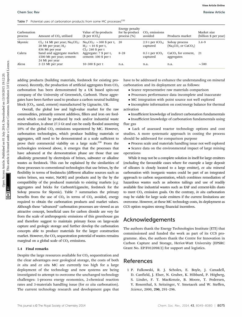
This journal is©The Royal Society of Chemistry 2014 Chem. Soc. Rev., 2014, 43, 8049--8080 | 8075
adding products (building materials, feedstock for existing pro-cesses). Recently, the production of artificial aggregates from CO2
carbonation has been demonstrated by a UK based spin-outcompany of the University of Greenwich, Carbon8. These aggre-gates have been further used to produce a carbon neutral buildingblock (CO2, sand, cement) manufactured by Lignacite, UK.
Overall, the global low and high-value market for the rawcommodities, primarily cement additives, fillers and iron ore feed-stock which could be produced by rock and/or industrial wastemineralisation, is about 27.5 Gt and can be easily flooded assuming10% of the global CO2 emissions sequestered by MC. However,carbonation technologies, which produce building materials oraggregates, still need to be demonstrated at a scale sufficient toprove their commercial viability on a large scale.230 From thetechnologies reviewed above, it emerges that the processes thathave advanced at the demonstration phase are those that usealkalinity generated by electrolysis of brines, saltwater or alkalinewastes as feedstock. This can be explained by the similarities ofthese processes to conventional technologies that use brines, by theflexibility in terms of feedstocks (different alkaline sources such asvaries brines, sea water, NaOH) and products and by the by thecompatibility of the produced materials to existing markets (e.g.aggregates and bricks for Carbon8/Ligancite, feedstock for theSolvay process for Skyonic). Table 7 summarises the primarybenefits from the use of CO2 in terms of CO2 avoided, energyrequired to obtain the carbonation products and market values.Although these ‘‘advanced’’ carbonation processes are viewed as anattractive concept, beneficial uses for carbon dioxide are very farfrom the scale of anthropogenic emissions of this greenhouse gasand therefore suggest to maintain primary focus on large-scalecapture and geologic storage and further develop the carbonationconcepts able to produce materials for the larger constructionmarket. However, the CO2 sequestration potential of wastes remainsmarginal on a global scale of CO2 emissions.
5.4 Final remarks
Despite the large resources available for CO2 sequestration andthe clear advantages over geological storage, the costs of bothin situ and ex situ MC are currently too high for a largedeployment of the technology and new systems are beinginvestigated to attempt to overcome the unchanged technologychallenges: 1-process energy economics, 2-chemical reactionrates and 3-materials handling issue (for ex situ carbonation).The current technology research and development gaps that
have to be addressed to enhance the understanding on mineralcarbonation and its deployment are as follows:� Scarce representative raw materials comparison� Processes performance data incomplete and inaccurate� MC integration with point source not well explored� Incomplete information on cost/energy balance for thermal
activation� Insufficient knowledge of indirect carbonation fundamentals� Insufficient knowledge of carbonation fundamentals using
flue gas� Lack of assessed reactor technology options and cost
studies. A more systematic approach in costing the processshould be addressed for comparison purpose� Process scale and materials handling issue not well explored� Scarce data on the environmental impact of large mining
operationsWhile it may not be a complete solution in itself for large emitters
(excluding the favourable cases where for example a large depositof silicates is closely located to a large emitter), ex situ mineralcarbonation with inorganic wastes could be part of an integratedapproach to carbon sequestration, which combines remediation ofhazardous wastes such as asbestos tailings and use of readilyavailable fine industrial wastes such as EAF and cement-kiln duststo meet CO2 emission goals. On the contrary, in situ carbonationmay be viable for large scale emitters if the current limitations areovercome. However, at these MC technology costs, its deployment asCCS option requires strong financial incentives.
Acknowledgements
The authors thank the Energy Technologies Institute (ETI) thatcommissioned and funded the work as part of its CCS pro-gramme. Also, the authors thank the Centre for Innovation inCarbon Capture and Storage, Heriot-Watt University (EPSRCGrant No. EP/F012098/2) for support and logistics.
References
1 P. Falkowski, R. J. Scholes, E. Boyle, J. Canadell,D. Canfield, J. Elser, N. Gruber, K. Hibbard, P. Hogberg,S. Linder, F. T. MacKenzie, B. Moore, T. Pedersen,Y. Rosenthal, S. Seitzinger, V. Smetacek and W. Steffen,Science, 2000, 290, 291–296.
Table 7 Potential uses of carbonation products from some MC processes230
Carbonationprocess Amount of CO2 utilised
Value of by-products($ per tCO2)
Energy penaltyfor by-productprocess (%)
CO2 emissionsavoided Products market
Market size(billion $ per year)
Skyonic Cl2: 14 Mt per year; Na2CO3:20 Mt per year; H2:836 Mt per year
Na2CO3: B300 $ per t,H2: B10 $ per t,Cl2: 240 $ per t
20 2.9 t per tCO2;captured
Solvay process(Na2CO3 or CaCO3)
3.4–9
Calera Sand and aggregate market:1500 Mt per year; cement:24 Mt per year
Aggregate: 7 $ per t,cement: 100 $ per t
8–28 0.5 t per tCO2
capturedCaCO3 for cement,aggregates
21
Alcoa 2–23 Mt per year 10–300 $ per t n.a. n.a. n.a. B500
Chem Soc Rev Review Article
Ope
n A
cces
s A
rtic
le. P
ublis
hed
on 0
1 Ju
ly 2
014.
Dow
nloa
ded
on 1
3/10
/201
5 19
:12:
20.
Thi
s ar
ticle
is li
cens
ed u
nder
a C
reat
ive
Com
mon
s A
ttrib
utio
n 3.
0 U
npor
ted
Lic
ence
.View Article Online
8076 | Chem. Soc. Rev., 2014, 43, 8049--8080 This journal is©The Royal Society of Chemistry 2014
2 IPCC, ed. R. K. Pachauri and A. Reisinger, IPCC, Geneva,Switzerland, 2007, p. 104.
3 S. Pacala and R. Socolow, Science, 2004, 305, 968–972.4 M. E. Boot-Handford, J. C. Abanades, E. J. Anthony, M. J.
Blunt, S. Brandani, N. Mac Dowell, J. R. Fernandez,M.-C. Ferrari, R. Gross, J. P. Hallett, R. S. Haszeldine,P. Heptonstall, A. Lyngfelt, Z. Makuch, E. Mangano,R. T. J. Porter, M. Pourkashanian, G. T. Rochelle,N. Shah, J. G. Yao and P. S. Fennell, Energy Environ. Sci.,2014, 7, 130–189.
5 B. Praetorius and K. Schumacher, Energy Policy, 2009, 37,5081–5093.
6 A. P. Hallenbeck and J. R. Kitchin, Ind. Eng. Chem. Res.,2013, 52, 10788–10794.
7 W. Seifritz, Nature, 1990, 345, 486.8 J. Sipila, S. Teir and R. Zevenhoven, Åbo Akademi Uni-
versity report VT 2008-1, 2008.9 IPCC, ed. B. Metz, O. Davidson, H. C. de Coninck, M. Loos
and L. A. Meyer, Cambridge University Press, Cambridge,United Kingdom and New York, NY, USA, 2005, p. 442.
10 A. Sanna, M. R. Hall and M. M. Maroto-Valer, EnergyEnviron. Sci., 2012, 5, 7781–7796.
11 G. Holmes and D. W. Keith, Philos. Trans. R. Soc., A, 2012,370, 4380–4403.
12 K. Z. House, A. C. Baclig, M. Ranjan, E. A. van Nierop,J. Wilcox and H. J. Herzog, Proc. Natl. Acad. Sci. U. S. A.,2011, 108(51), 20428–20433.
13 D. S. Goldberg, K. S. Lackner, P. Han, A. L. Slagle andT. Wang, Environ. Sci. Technol., 2013, 47, 7521–7529.
14 M. D. Eisaman, K. Parajuly, A. Tuganov, C. Eldershaw,N. Chang and K. A. Littau, Energy Environ. Sci., 2012, 5,7346–7352.
15 G. H. Rau, Environ. Sci. Technol., 2011, 45, 1088–1092.16 P. Renforth and T. Kruger, Energy Fuels, 2013, 27, 4199–4207.17 S. S. Salek, R. Kleerebezem, H. M. Jonkers, G.-J. Witkamp
and M. C. M. van Loosdrecht, Trends Biotechnol., 2013, 31,139–146.
18 M. Verduyn, H. Boerrigter, R. Oudwater, G.A.F. van Mossel,5th Trondheim CCS, 16–17th June 2009.
19 M. Verduyn, H. Geerlings, G. van Mossel and S. Vijayakumari,Energy Procedia, 2011, 4, 2885–2892.
20 H. Yan, J. Y. Zhang, Y. C. Zhao and C. G. Zheng, Sci. China:Technol. Sci., 2013, 56, 2219–2227.
21 A. Olajire, J. Pet. Sci. Eng., 2013, 109, 364–392.22 R. Zevenhoven, J. Fagerlund and J. K. Songok, Greenhouse
Gases: Sci. Technol., 2011, 1, 48–57.23 E. R. Bobicki, Q. Liu, Z. Xu and H. Zeng, Prog. Energy
Combust. Sci., 2012, 38, 302–320.24 S.-Y. Pan, E. E. Chang and P.-C. Chiang, Aerosol Air Qual.
Res., 2012, 12, 770–791.25 A. Sanna, M. Dri, M. R. Hall and M. Maroto-Valer,
Appl. Energy, 2012, 99, 545–554.26 A. Kirchofer, A. Becker, A. Brandt and J. Wilcox, Environ.
Sci. Technol., 2013, 47, 7548–7554.27 A.-h. A. Park, P. Kelemen, J. Matter, G. Gadikota,
Geo-Chemo-Mechanical Studies for Permanent Storage of
CO2 in Geologic Formations, DE-FE0002386, Columbia Uni-versity, New York, U.S. Department of Energy National EnergyTechnology Laboratory Carbon Storage R&D Project ReviewMeeting, August 21–23, 2012, http://www.netl.doe.gov/.
28 R. Berner, A. Lasaga and R. Garrels, Am. J. Sci., 1983, 283,641–683.
29 S. Gislason, E. Oelkers, E. Eiriksdottir, M. Kardjilov,G. Gisladottir, B. Sigfusso, A. Snorrason, S. Elefsen,J. Hardardottir, P. Torssander and N. Pskarsson, EarthPlanet. Sci. Lett., 2009, 277, 213–222.
30 B. M. Reinhardt, Schweiz. Mineral. Petrogr. Mitt., 1969, 49, 1–30.31 F. Boudier and R. G. Coleman, J. Geophys. Res., 1981, 86,
2573–2592.32 P. Kelem and J. Matter, PNAS, 2008, 105/45, 17295–17300.33 A. Paukert, J. Matter, P. Kelemen, E. Shock and J. Havig,
Chem. Geol., 2012, 330/331, 86–100.34 G. D. Nicholls, Mineral. Mag., 1965, 34/268, 373–388.35 C. Dessert, B. Dupre’, J. Gaillardet, L. Francois and
C. Allegre, Chem. Geol., 2003, 202, 257–273.36 E. Rosenthal, J. Hydrol., 1987, 89/3–4, 329–352.37 J. Matter and T. Takahashi, Geochem., Geophys., Geosyst.,
2007, 8/2, 1–19.38 K. House, D. Schrag, C. Harvey and K. Lackner, PNAS, 2006,
103, 12291–12295.39 P. Olsen, D. Kent, B. Cornet, W. Witte and R. Schlische,
Geol. Soc. Am. Bull., 1996, 108/1, 40–77.40 B. McGrail, A. Spane, E. Sullivan, D. Bacon and G. Hund,
Energy Procedia, 2011, 4, 5653–5660.41 N. Zakharova, D. Goldberg, C. Sullivan, M. Herron and
J. Grau, Geochem., Geophys., Geosyst., 2012, 13/11, 1–22.42 T. Flaathen, S. Gislason, E. Oelkers and A. Sveinbjornsdottir,
Appl. Geochem., 2009, 24, 463–474.43 S. Gislason, D. Wolff-Boenisch, A. Stefansson, E. Olelkers,
E. Gunnlaugsson, H. Sigurdardottir, B. Sigfusson, W. Broecker,J. Matter, M. Stute, G. Axelsson and T. Fridriksson, Int.J. Greenhouse Gas Control, 2010, 4, 537–545.
44 J. Matter and P. Kelemen, Nat. Geosci., 2009, 2, 837–841.45 J. Matter, S. Broecker, S. Gislason, E. Gunnlaugsson,
E. Oelkers, M. Stute, H. Sigurdardottir, A. Stefansson,H. Alfredsson, E. Aradottir, G. Axelsson, B. Sigfusson andD. Wolff-Boenisch, Energy Procedia, 2011, 4, 5579–5585.
46 B. Sigfusson, 8th CO2GeoNet Open Forum, S. Servolo, Italy2013.
47 D. Becker, EOS, Trans., Am. Geophys. Union, 1998, 79,369–378.
48 D. Goldberg, T. Takahashi and A. Slagle, PNAS, 2008,105/29, 9920–9925.
49 P. Olsen, J. Smoot, P. Le Tourneau, Fieldtrip for the 11thAnnual Continental Scientific Drilling Workshop, Arlington,2007, 1–45.
50 D. Folger, J. Hathaway, R. Christopher, P. Valentine andS. Poag, U.S. Geol. Surv. Circ., 1978, 773, 1–28.
51 T. Maguire, R. Sheridan and R. Volkert, Geodynamics, 2004,37, 457–485.
52 D. Goldberg, D. Kent and P. Olsen, PNAS, 2010, 107/4,1327–1332.
Review Article Chem Soc Rev
Ope
n A
cces
s A
rtic
le. P
ublis
hed
on 0
1 Ju
ly 2
014.
Dow
nloa
ded
on 1
3/10
/201
5 19
:12:
20.
Thi
s ar
ticle
is li
cens
ed u
nder
a C
reat
ive
Com
mon
s A
ttrib
utio
n 3.
0 U
npor
ted
Lic
ence
.View Article Online
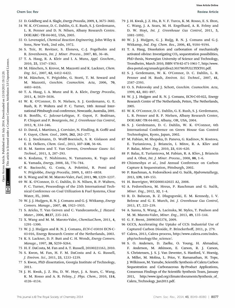
This journal is©The Royal Society of Chemistry 2014 Chem. Soc. Rev., 2014, 43, 8049--8080 | 8077
53 D. Goldberg and A. Slagle, Energy Procedia, 2009, 1, 3675–3682.54 W. K. O’Connor, D. C. Dahlin, G. E. Rush, S. J. Gerdemann,
L. R. Penner and D. N. Nilsen, Albany Research Centre.DOE/ARC–TR-04-002, USA, 2005.
55 O. Levenspiel, Chemical Reaction Engineering, John Wiley &Sons, New York, 2nd edn, 1972.
56 S. Teir, H. Revitzer, S. Eloneva, C.-J. Fogelholm andR. Zevenhoven, Int. J. Miner. Process., 2007, 83, 36–46.
57 T. A. Haug, R. A. Kleiv and I. A. Munz, Appl. Geochem.,2010, 25, 1547–1563.
58 M. Hanchen, S. Krevor, M. Mazzotti and K. Lackner, Chem.Eng. Sci., 2007, 62, 6412–6422.
59 M. Hanchen, V. Prigiobbe, G. Storti, T. M. Seward andM. Mazzotti, Geochim. Cosmochim. Acta, 2006, 70,4403–4416.
60 T. A. Haug, I. A. Munz and R. A. Kleiv, Energy Procedia,2011, 4, 5029–5036.
61 W. K. O’Connor, D. N. Nielsen, S. J. Gerdemann, G. E.Rush, R. P. Waltera and P. C. Turner, 18th Annual Inter-national Pittsburgh coal conference, Newcastle, Australia, 2001.
62 B. Bonfils, C. Julcour-Lebigue, F. Guyot, F. Bodenan,P. Chiquet and F. Bourgeois, Int. J. Greenhouse Gas Control,2012, 9, 334–346.
63 D. Daval, I. Martinez, J. Corvisier, N. Findling, B. Goffe andF. Guyot, Chem. Geol., 2009, 262, 262–277.
64 G. J. Stockmann, D. Wolff-Boenisch, S. R. Gislason andE. H. Oelkers, Chem. Geol., 2013, 337–338, 56–66.
65 R. M. Santos and T. Van Gerven, Greenhouse Gases: Sci.Technol., 2011, 1, 287–293.
66 S. Kodama, T. Nishimoto, N. Yamamoto, K. Yogo andK. Yamada, Energy, 2008, 33, 776–784.
67 R. Baciocchi, G. Costa, A. Polettini, R. Pomi andV. Prigiobbe, Energy Procedia, 2009, 1, 4851–4858.
68 X. Wang and M. M. Maroto-Valer, Fuel, 2011, 90, 1229–1237.69 W. K. O’Connor, D. C. Dahlin, D. N. Nilsen, R. P. Walters,
P. C. Turner, Proceedings of the 25th International Tech-nical Conference on Coal Utilization & Fuel Systems, ClearWater, FL, 2000.
70 W. J. J. Huijgen, R. N. J. Comans and G.-J. Witkamp, EnergyConvers. Manage., 2007, 48, 1923–1935.
71 S. Arickx, T. Van Gerven and C. Vandecasteele, J. Hazard.Mater., 2006, B137, 235–243.
72 X. Wang and M. M. Maroto-Valer, ChemSusChem, 2011, 4,1291–1300.
73 W. J. J. Huijgen and R. N. J. Comans, ECN-C-03016 ECN-C-03-016, Energy Research Centre of the Netherlands, 2003.
74 K. S. Lackner, D. P. Butt and C. H. Wendt, Energy Convers.Manage., 1997, 38, S259–S264.
75 H. F. DaCosta, M. Fan and A. T. Russell, 20100221163, 2010.76 S. Kwon, M. Fan, H. F. M. DaCosta and A. G. Russell,
J. Environ. Sci., 2011, 23, 1233–1239.77 S. Kwon, PhD dissertation, Georgia Institute of Technology,
2011.78 J. H. Kwak, J. Z. Hu, D. W. Hoyt, J. A. Sears, C. Wang,
K. M. Rosso and A. R. Felmy, J. Phys. Chem., 2010, 114,4126–4134.
79 J. H. Kwak, J. Z. Hu, R. V. F. Turcu, K. M. Rosso, E. S. Ilton,C. Wang, J. A. Sears, M. H. Engelhard, A. R. Felmy andD. W. Hoyt, Int. J. Greenhouse Gas Control, 2011, 5,1081–1092.
80 W. J. J. Huijgen, G. J. Ruijg, R. N. J. Comans and G.-J.Witkamp, Ind. Eng. Chem. Res., 2006, 45, 9184–9194.
81 T. A. Haug, Dissolution and carbonation of mechanicallyactivated olivine: Investigating CO2 sequestration possibilities,PhD thesis, Norwegian University of Science and Technology,Trondheim, March 2010, ISBN 978-82-471-1961-7, http://www.diva-portal.org/smash/get/diva2:303780/FULLTEXT01.pdf.
82 S. J. Gerdemann, W. K. O’Connor, D. C. Dahlin, L. R.Penner and H. Rush, Environ. Sci. Technol., 2007, 41,2587–2593.
83 O. S. Pokrovsky and J. Schott, Geochim. Cosmochim. Acta,1999, 63, 881–897.
84 W. J. J. Huijgen and R. N. J. Comans, ECN-C-05-022, EnergyResearch Centre of The Netherlands, Petten, The Netherlands,2005.
85 W. K. O’Connor, D. C. Dahlin, G. E. Rush, S. J. Gerdemann,L. R. Penner and R. P. Nielsen, Albany Research Center,DOE/ARC-TR-04-002, Albany, OR, USA, 2004.
86 S. J. Gerdemann, D. C. Dahlin, W. K. O’Connor, 6thInternational Conference on Green House Gas ControlTechnologies, Kyoto, Japan, 2002.
87 M. Fabian, M. Shopska, D. Paneva, G. Kadinov, N. Kostova,E. Turianicova, J. Briancin, I. Mitov, R. A. Kliev andP. Balaz, Miner. Eng., 2010, 23, 616–620.
88 P. Balaz, E. Turianicova, M. Fabian, R. A. Kliev, J. Briancinand A. Obut, Int. J. Miner. Process., 2008, 88, 1–6.
89 Chizmeshya et al., 2nd Annual Conference on CarbonCapture & Sequestration, Pittsburgh, 2002.
90 P. Raschman, A. Fedorockova and G. Sucik, Hydrometallurgy,2013, 139, 149–153.
91 H. Boerrigter, WO2008142025 A2, 2008.92 A. Fedorockova, M. Hreus, P. Raschman and G. Sucik,
Miner. Eng., 2012, 32, 1–4.93 R. D. Balucan, B. Z. Dlugogorski, E. M. Kennedy, I. V.
Belovac and G. E. Murch, Int. J. Greenhouse Gas Control,2013, 17, 225–239.
94 A. Sanna, X. Wang, A. Lacinska, M. Styles, T. Paulson andM. M. Maroto-Valer, Miner. Eng., 2013, 49, 135–144.
95 G. F. Brent, 20090305378, 2009.96 GCCS, Accelerating the Uptake of CCS: Industrial Use of
Captured Carbon Dioxide, P. Brinckerhoff, 2011, p. 279.97 Calera, 2013, Calera process, http://www.calera.com/index.
php/technology/the_science/.98 S. O. Andersen, D. Zaelke, O. Young, H. Ahmadzai,
F. Anderson, M. Atkinson, E. Carson, R. J. Carson,S. Christensen, J. S. J. Van Deventer, S. Hanford, V. Hoenig,A. Miller, M. Molina, L. Price, V. Ramanathan, H. Tope,J. Wilkinson, M. Yamabe, Scientific Synthesis of Calera CarbonSequestration and Carbonaceous By-Product Applications,Consensus Findings of the Scientific Synthesis Team, January2011, http://www.igsd.org/climate/documents/Synthesis_of_Calera_Technology_Jan2011.pdf.
Chem Soc Rev Review Article
Ope
n A
cces
s A
rtic
le. P
ublis
hed
on 0
1 Ju
ly 2
014.
Dow
nloa
ded
on 1
3/10
/201
5 19
:12:
20.
Thi
s ar
ticle
is li
cens
ed u
nder
a C
reat
ive
Com
mon
s A
ttrib
utio
n 3.
0 U
npor
ted
Lic
ence
.View Article Online
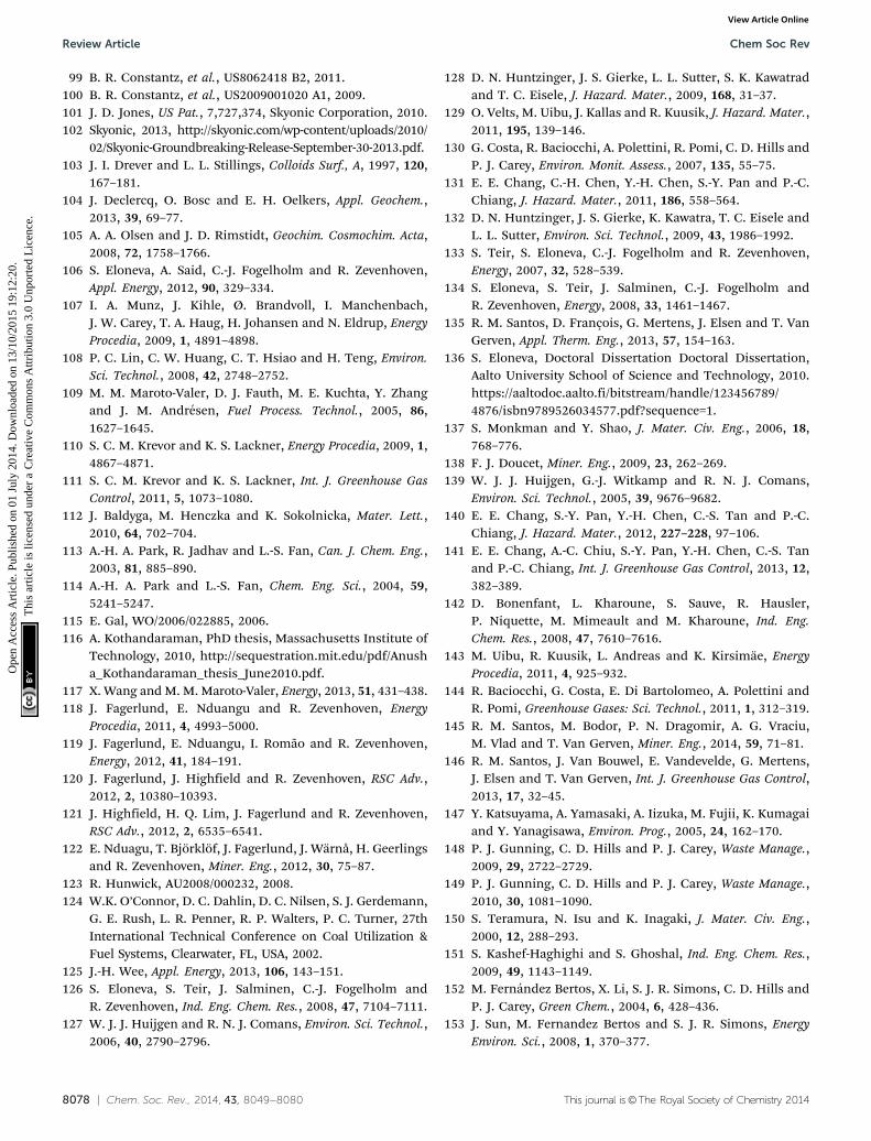
8078 | Chem. Soc. Rev., 2014, 43, 8049--8080 This journal is©The Royal Society of Chemistry 2014
99 B. R. Constantz, et al., US8062418 B2, 2011.100 B. R. Constantz, et al., US2009001020 A1, 2009.101 J. D. Jones, US Pat., 7,727,374, Skyonic Corporation, 2010.102 Skyonic, 2013, http://skyonic.com/wp-content/uploads/2010/
02/Skyonic-Groundbreaking-Release-September-30-2013.pdf.103 J. I. Drever and L. L. Stillings, Colloids Surf., A, 1997, 120,
167–181.104 J. Declercq, O. Bosc and E. H. Oelkers, Appl. Geochem.,
2013, 39, 69–77.105 A. A. Olsen and J. D. Rimstidt, Geochim. Cosmochim. Acta,
2008, 72, 1758–1766.106 S. Eloneva, A. Said, C.-J. Fogelholm and R. Zevenhoven,
Appl. Energy, 2012, 90, 329–334.107 I. A. Munz, J. Kihle, Ø. Brandvoll, I. Manchenbach,
J. W. Carey, T. A. Haug, H. Johansen and N. Eldrup, EnergyProcedia, 2009, 1, 4891–4898.
108 P. C. Lin, C. W. Huang, C. T. Hsiao and H. Teng, Environ.Sci. Technol., 2008, 42, 2748–2752.
109 M. M. Maroto-Valer, D. J. Fauth, M. E. Kuchta, Y. Zhangand J. M. Andresen, Fuel Process. Technol., 2005, 86,1627–1645.
110 S. C. M. Krevor and K. S. Lackner, Energy Procedia, 2009, 1,4867–4871.
111 S. C. M. Krevor and K. S. Lackner, Int. J. Greenhouse GasControl, 2011, 5, 1073–1080.
112 J. Baldyga, M. Henczka and K. Sokolnicka, Mater. Lett.,2010, 64, 702–704.
113 A.-H. A. Park, R. Jadhav and L.-S. Fan, Can. J. Chem. Eng.,2003, 81, 885–890.
114 A.-H. A. Park and L.-S. Fan, Chem. Eng. Sci., 2004, 59,5241–5247.
115 E. Gal, WO/2006/022885, 2006.116 A. Kothandaraman, PhD thesis, Massachusetts Institute of
Technology, 2010, http://sequestration.mit.edu/pdf/Anusha_Kothandaraman_thesis_June2010.pdf.
117 X. Wang and M. M. Maroto-Valer, Energy, 2013, 51, 431–438.118 J. Fagerlund, E. Nduangu and R. Zevenhoven, Energy
Procedia, 2011, 4, 4993–5000.119 J. Fagerlund, E. Nduangu, I. Romao and R. Zevenhoven,
Energy, 2012, 41, 184–191.120 J. Fagerlund, J. Highfield and R. Zevenhoven, RSC Adv.,
2012, 2, 10380–10393.121 J. Highfield, H. Q. Lim, J. Fagerlund and R. Zevenhoven,
RSC Adv., 2012, 2, 6535–6541.122 E. Nduagu, T. Bjorklof, J. Fagerlund, J. Warnå, H. Geerlings
and R. Zevenhoven, Miner. Eng., 2012, 30, 75–87.123 R. Hunwick, AU2008/000232, 2008.124 W.K. O’Connor, D. C. Dahlin, D. C. Nilsen, S. J. Gerdemann,
G. E. Rush, L. R. Penner, R. P. Walters, P. C. Turner, 27thInternational Technical Conference on Coal Utilization &Fuel Systems, Clearwater, FL, USA, 2002.
125 J.-H. Wee, Appl. Energy, 2013, 106, 143–151.126 S. Eloneva, S. Teir, J. Salminen, C.-J. Fogelholm and
R. Zevenhoven, Ind. Eng. Chem. Res., 2008, 47, 7104–7111.127 W. J. J. Huijgen and R. N. J. Comans, Environ. Sci. Technol.,
2006, 40, 2790–2796.
128 D. N. Huntzinger, J. S. Gierke, L. L. Sutter, S. K. Kawatradand T. C. Eisele, J. Hazard. Mater., 2009, 168, 31–37.
129 O. Velts, M. Uibu, J. Kallas and R. Kuusik, J. Hazard. Mater.,2011, 195, 139–146.
130 G. Costa, R. Baciocchi, A. Polettini, R. Pomi, C. D. Hills andP. J. Carey, Environ. Monit. Assess., 2007, 135, 55–75.
131 E. E. Chang, C.-H. Chen, Y.-H. Chen, S.-Y. Pan and P.-C.Chiang, J. Hazard. Mater., 2011, 186, 558–564.
132 D. N. Huntzinger, J. S. Gierke, K. Kawatra, T. C. Eisele andL. L. Sutter, Environ. Sci. Technol., 2009, 43, 1986–1992.
133 S. Teir, S. Eloneva, C.-J. Fogelholm and R. Zevenhoven,Energy, 2007, 32, 528–539.
134 S. Eloneva, S. Teir, J. Salminen, C.-J. Fogelholm andR. Zevenhoven, Energy, 2008, 33, 1461–1467.
135 R. M. Santos, D. François, G. Mertens, J. Elsen and T. VanGerven, Appl. Therm. Eng., 2013, 57, 154–163.
136 S. Eloneva, Doctoral Dissertation Doctoral Dissertation,Aalto University School of Science and Technology, 2010.https://aaltodoc.aalto.fi/bitstream/handle/123456789/4876/isbn9789526034577.pdf?sequence=1.
137 S. Monkman and Y. Shao, J. Mater. Civ. Eng., 2006, 18,768–776.
138 F. J. Doucet, Miner. Eng., 2009, 23, 262–269.139 W. J. J. Huijgen, G.-J. Witkamp and R. N. J. Comans,
Environ. Sci. Technol., 2005, 39, 9676–9682.140 E. E. Chang, S.-Y. Pan, Y.-H. Chen, C.-S. Tan and P.-C.
Chiang, J. Hazard. Mater., 2012, 227–228, 97–106.141 E. E. Chang, A.-C. Chiu, S.-Y. Pan, Y.-H. Chen, C.-S. Tan
and P.-C. Chiang, Int. J. Greenhouse Gas Control, 2013, 12,382–389.
142 D. Bonenfant, L. Kharoune, S. Sauve, R. Hausler,P. Niquette, M. Mimeault and M. Kharoune, Ind. Eng.Chem. Res., 2008, 47, 7610–7616.
143 M. Uibu, R. Kuusik, L. Andreas and K. Kirsimae, EnergyProcedia, 2011, 4, 925–932.
144 R. Baciocchi, G. Costa, E. Di Bartolomeo, A. Polettini andR. Pomi, Greenhouse Gases: Sci. Technol., 2011, 1, 312–319.
145 R. M. Santos, M. Bodor, P. N. Dragomir, A. G. Vraciu,M. Vlad and T. Van Gerven, Miner. Eng., 2014, 59, 71–81.
146 R. M. Santos, J. Van Bouwel, E. Vandevelde, G. Mertens,J. Elsen and T. Van Gerven, Int. J. Greenhouse Gas Control,2013, 17, 32–45.
147 Y. Katsuyama, A. Yamasaki, A. Iizuka, M. Fujii, K. Kumagaiand Y. Yanagisawa, Environ. Prog., 2005, 24, 162–170.
148 P. J. Gunning, C. D. Hills and P. J. Carey, Waste Manage.,2009, 29, 2722–2729.
149 P. J. Gunning, C. D. Hills and P. J. Carey, Waste Manage.,2010, 30, 1081–1090.
150 S. Teramura, N. Isu and K. Inagaki, J. Mater. Civ. Eng.,2000, 12, 288–293.
151 S. Kashef-Haghighi and S. Ghoshal, Ind. Eng. Chem. Res.,2009, 49, 1143–1149.
152 M. Fernandez Bertos, X. Li, S. J. R. Simons, C. D. Hills andP. J. Carey, Green Chem., 2004, 6, 428–436.
153 J. Sun, M. Fernandez Bertos and S. J. R. Simons, EnergyEnviron. Sci., 2008, 1, 370–377.
Review Article Chem Soc Rev
Ope
n A
cces
s A
rtic
le. P
ublis
hed
on 0
1 Ju
ly 2
014.
Dow
nloa
ded
on 1
3/10
/201
5 19
:12:
20.
Thi
s ar
ticle
is li
cens
ed u
nder
a C
reat
ive
Com
mon
s A
ttrib
utio
n 3.
0 U
npor
ted
Lic
ence
.View Article Online
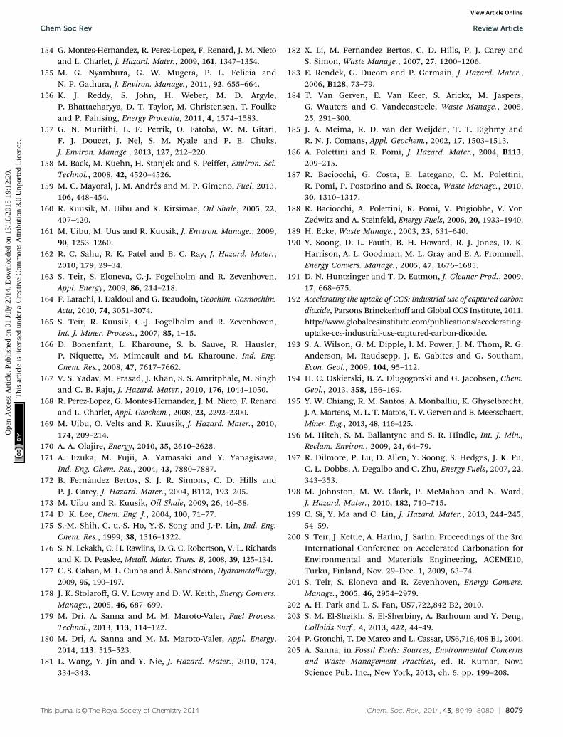
This journal is©The Royal Society of Chemistry 2014 Chem. Soc. Rev., 2014, 43, 8049--8080 | 8079
154 G. Montes-Hernandez, R. Perez-Lopez, F. Renard, J. M. Nietoand L. Charlet, J. Hazard. Mater., 2009, 161, 1347–1354.
155 M. G. Nyambura, G. W. Mugera, P. L. Felicia andN. P. Gathura, J. Environ. Manage., 2011, 92, 655–664.
156 K. J. Reddy, S. John, H. Weber, M. D. Argyle,P. Bhattacharyya, D. T. Taylor, M. Christensen, T. Foulkeand P. Fahlsing, Energy Procedia, 2011, 4, 1574–1583.
157 G. N. Muriithi, L. F. Petrik, O. Fatoba, W. M. Gitari,F. J. Doucet, J. Nel, S. M. Nyale and P. E. Chuks,J. Environ. Manage., 2013, 127, 212–220.
158 M. Back, M. Kuehn, H. Stanjek and S. Peiffer, Environ. Sci.Technol., 2008, 42, 4520–4526.
159 M. C. Mayoral, J. M. Andres and M. P. Gimeno, Fuel, 2013,106, 448–454.
160 R. Kuusik, M. Uibu and K. Kirsimae, Oil Shale, 2005, 22,407–420.
161 M. Uibu, M. Uus and R. Kuusik, J. Environ. Manage., 2009,90, 1253–1260.
162 R. C. Sahu, R. K. Patel and B. C. Ray, J. Hazard. Mater.,2010, 179, 29–34.
163 S. Teir, S. Eloneva, C.-J. Fogelholm and R. Zevenhoven,Appl. Energy, 2009, 86, 214–218.
164 F. Larachi, I. Daldoul and G. Beaudoin, Geochim. Cosmochim.Acta, 2010, 74, 3051–3074.
165 S. Teir, R. Kuusik, C.-J. Fogelholm and R. Zevenhoven,Int. J. Miner. Process., 2007, 85, 1–15.
166 D. Bonenfant, L. Kharoune, S. b. Sauve, R. Hausler,P. Niquette, M. Mimeault and M. Kharoune, Ind. Eng.Chem. Res., 2008, 47, 7617–7662.
167 V. S. Yadav, M. Prasad, J. Khan, S. S. Amritphale, M. Singhand C. B. Raju, J. Hazard. Mater., 2010, 176, 1044–1050.
168 R. Perez-Lopez, G. Montes-Hernandez, J. M. Nieto, F. Renardand L. Charlet, Appl. Geochem., 2008, 23, 2292–2300.
169 M. Uibu, O. Velts and R. Kuusik, J. Hazard. Mater., 2010,174, 209–214.
170 A. A. Olajire, Energy, 2010, 35, 2610–2628.171 A. Iizuka, M. Fujii, A. Yamasaki and Y. Yanagisawa,
Ind. Eng. Chem. Res., 2004, 43, 7880–7887.172 B. Fernandez Bertos, S. J. R. Simons, C. D. Hills and
P. J. Carey, J. Hazard. Mater., 2004, B112, 193–205.173 M. Uibu and R. Kuusik, Oil Shale, 2009, 26, 40–58.174 D. K. Lee, Chem. Eng. J., 2004, 100, 71–77.175 S.-M. Shih, C. u.-S. Ho, Y.-S. Song and J.-P. Lin, Ind. Eng.
Chem. Res., 1999, 38, 1316–1322.176 S. N. Lekakh, C. H. Rawlins, D. G. C. Robertson, V. L. Richards
and K. D. Peaslee, Metall. Mater. Trans. B, 2008, 39, 125–134.177 C. S. Gahan, M. L. Cunha and Å. Sandstrom, Hydrometallurgy,
2009, 95, 190–197.178 J. K. Stolaroff, G. V. Lowry and D. W. Keith, Energy Convers.
Manage., 2005, 46, 687–699.179 M. Dri, A. Sanna and M. M. Maroto-Valer, Fuel Process.
Technol., 2013, 113, 114–122.180 M. Dri, A. Sanna and M. M. Maroto-Valer, Appl. Energy,
2014, 113, 515–523.181 L. Wang, Y. Jin and Y. Nie, J. Hazard. Mater., 2010, 174,
334–343.
182 X. Li, M. Fernandez Bertos, C. D. Hills, P. J. Carey andS. Simon, Waste Manage., 2007, 27, 1200–1206.
183 E. Rendek, G. Ducom and P. Germain, J. Hazard. Mater.,2006, B128, 73–79.
184 T. Van Gerven, E. Van Keer, S. Arickx, M. Jaspers,G. Wauters and C. Vandecasteele, Waste Manage., 2005,25, 291–300.
185 J. A. Meima, R. D. van der Weijden, T. T. Eighmy andR. N. J. Comans, Appl. Geochem., 2002, 17, 1503–1513.
186 A. Polettini and R. Pomi, J. Hazard. Mater., 2004, B113,209–215.
187 R. Baciocchi, G. Costa, E. Lategano, C. M. Polettini,R. Pomi, P. Postorino and S. Rocca, Waste Manage., 2010,30, 1310–1317.
188 R. Baciocchi, A. Polettini, R. Pomi, V. Prigiobbe, V. VonZedwitz and A. Steinfeld, Energy Fuels, 2006, 20, 1933–1940.
189 H. Ecke, Waste Manage., 2003, 23, 631–640.190 Y. Soong, D. L. Fauth, B. H. Howard, R. J. Jones, D. K.
Harrison, A. L. Goodman, M. L. Gray and E. A. Frommell,Energy Convers. Manage., 2005, 47, 1676–1685.
191 D. N. Huntzinger and T. D. Eatmon, J. Cleaner Prod., 2009,17, 668–675.
192 Accelerating the uptake of CCS: industrial use of captured carbondioxide, Parsons Brinckerhoff and Global CCS Institute, 2011.http://www.globalccsinstitute.com/publications/accelerating-uptake-ccs-industrial-use-captured-carbon-dioxide.
193 S. A. Wilson, G. M. Dipple, I. M. Power, J. M. Thom, R. G.Anderson, M. Raudsepp, J. E. Gabites and G. Southam,Econ. Geol., 2009, 104, 95–112.
194 H. C. Oskierski, B. Z. Dlugogorski and G. Jacobsen, Chem.Geol., 2013, 358, 156–169.
195 Y. W. Chiang, R. M. Santos, A. Monballiu, K. Ghyselbrecht,J. A. Martens, M. L. T. Mattos, T. V. Gerven and B. Meesschaert,Miner. Eng., 2013, 48, 116–125.
196 M. Hitch, S. M. Ballantyne and S. R. Hindle, Int. J. Min.,Reclam. Environ., 2009, 24, 64–79.
197 R. Dilmore, P. Lu, D. Allen, Y. Soong, S. Hedges, J. K. Fu,C. L. Dobbs, A. Degalbo and C. Zhu, Energy Fuels, 2007, 22,343–353.
198 M. Johnston, M. W. Clark, P. McMahon and N. Ward,J. Hazard. Mater., 2010, 182, 710–715.
199 C. Si, Y. Ma and C. Lin, J. Hazard. Mater., 2013, 244–245,54–59.
200 S. Teir, J. Kettle, A. Harlin, J. Sarlin, Proceedings of the 3rdInternational Conference on Accelerated Carbonation forEnvironmental and Materials Engineering, ACEME10,Turku, Finland, Nov. 29–Dec. 1, 2009, 63–74.
201 S. Teir, S. Eloneva and R. Zevenhoven, Energy Convers.Manage., 2005, 46, 2954–2979.
202 A.-H. Park and L.-S. Fan, US7,722,842 B2, 2010.203 S. M. El-Sheikh, S. El-Sherbiny, A. Barhoum and Y. Deng,
Colloids Surf., A, 2013, 422, 44–49.204 P. Gronchi, T. De Marco and L. Cassar, US6,716,408 B1, 2004.205 A. Sanna, in Fossil Fuels: Sources, Environmental Concerns
and Waste Management Practices, ed. R. Kumar, NovaScience Pub. Inc., New York, 2013, ch. 6, pp. 199–208.
Chem Soc Rev Review Article
Ope
n A
cces
s A
rtic
le. P
ublis
hed
on 0
1 Ju
ly 2
014.
Dow
nloa
ded
on 1
3/10
/201
5 19
:12:
20.
Thi
s ar
ticle
is li
cens
ed u
nder
a C
reat
ive
Com
mon
s A
ttrib
utio
n 3.
0 U
npor
ted
Lic
ence
.View Article Online
8080 | Chem. Soc. Rev., 2014, 43, 8049--8080 This journal is©The Royal Society of Chemistry 2014
206 R. E. F. Lindeboom, I. Ferrer, J. Weijma and J. B. van Lier,Water Res., 2010, 47, 3742–3751.
207 C. Y. Tai and F. B. Chen, AIChE J., 1998, 1790–1798.208 G. Li, Z. Li and H. Ma, Int. J. Miner. Process., 2013, 123,
25–31.209 S. Wanjari, C. Prabhu, N. Labhsetwar and S. Rayalu, J. Mol.
Catal. B: Enzym., 2013, 93, 15–22.210 N. Favre, M. L. Christ and A. C. Pierre, J. Mol. Catal. B:
Enzym., 2009, 60, 163–170.211 P. C. Sahoo, Y. N. Jang and S. W. Lee, J. Cryst. Growth, 2013,
373, 96–101.212 A. Said, H.-P. Mattila, M. Jarvinen and R. Zevenhoven,
Appl. Energy, 2012, 112, 765–771.213 M. Faatz, F. Grohn and G. Wegner, Adv. Mater., 2004, 16,
996–1000.214 G. Montes-Hernandez, F. Renard, R. Chiriac, N. Findling,
J. Ghanbaja and F. Toche, Chem. Eng. J., 2013, 214,139–148.
215 W. Wang, S. Wang, X. Ma and J. Gong, Chem. Soc. Rev.,2011, 40, 3703–3727.
216 E. V. Kondratenko, G. Mul, J. Baltrusaitis, G. O. Larrazabaland J. Perez-Ramırez, Energy Environ. Sci., 2013, 6,3112–3135.
217 J. Qiao, Y. Liu, F. Hong and J. Zhang, Chem. Soc. Rev., 2014,43, 631–675.
218 W. S. Broecker, Elements, 2008, 4, 4295–4297.219 F. Bodenan, F. Bourgeois, C. Petiot, T. Auge, B. Bonfils,
C. Julcour, F. Guyot, A. Boukary, J. Tremosa, A. Lassin,P. Chiquet, 4th International Conference on AcceleratedCarbonation for Environmental and Materials Engineering,10–12 Apr 2013, Leuven, Belgium.
220 M. Hitch and G. M. Dipple, Miner. Eng., 2012, 39, 268–275.221 K. J. Reddy, B. Reynolds and M. D. Argyle, in Proceedings
of the 4th international Conference on Accelerated Carbo-nation for Environmental and Materials Engineering,Leuven, Belgium, 2013, pp. 175–183.
222 P. J. Gunning, C. D. Hills and P. J. Carey, in Proceedings ofthe 4th International Conference on Accelerated Carbona-tion and Materials Engineering Leuven, Belgium, 2013,pp. 185–192.
223 G. Jones, G. Joshi, M. Clark and D. McConchie, Environ.Chem., 2006, 3, 297–303.
224 B. E. H. Jones and R. J. Haynes, Crit. Rev. Environ. Sci.Technol., 2011, 41, 271–315.
225 D. J. Cooling, in Paste 2007—Proceedings of the TenthInternational Seminar on Paste and Thickened Tailings,Australian Center for Geomechanics, ed. A. B. Fourie andR. J. Jewell, Perth, Australia, 2007, pp. 3–15.
226 S. R. Gislason and E. H. Oelkers, Science, 2014, 344,373–374.
227 J. K. Stolaroff, G. V. Lowry and D. W. Keith, Energy Convers.Manage., 2005, 46, 687–699.
228 GCCSI, Strategic Analysis of the Global Status of CarbonCapture and Storage Report 2: Economic Assessment ofCarbon Capture and Storage Technologies. 2009. GlobalCCS Institute, GPO Box 828, Canberra ACT 2601 Australia.
229 IMC, 2008, Alberta CO2 Capture Cost Survey and SupplyCurve, prepared for the Alberta CCS Development Council.Ian Murray and Co. Ltd. http://www.canadiancleanpowercoalition.com/.
230 CSLF, 2012, Annual Meeting Documents Book, CSLF-T-2012-10, 4 September 2012, Perth, Australia.
Review Article Chem Soc Rev
Ope
n A
cces
s A
rtic
le. P
ublis
hed
on 0
1 Ju
ly 2
014.
Dow
nloa
ded
on 1
3/10
/201
5 19
:12:
20.
Thi
s ar
ticle
is li
cens
ed u
nder
a C
reat
ive
Com
mon
s A
ttrib
utio
n 3.
0 U
npor
ted
Lic
ence
.View Article Online
![Carbonation PH-Final-Meheen [Read-Only] · PDF fileI. The Basics of Carbonation - Dave Meheen, President, Meheen Manufacturing II. Principles of Natural Carbonation Marty Velas, Director](https://img.pdfslide.net/doc/110x75/5a6fa97c7f8b9a9d538b49c7/carbonation-ph-final-meheen-read-only-nbsppdf-filei-the-basics-of.jpg)